Contents
- I. Module Introduction
- II. Introduction to Main Chips
- 2.1 Chip Overview
- 2.2 Pin Definition
- 2.3 Functional Block Diagram
- 2.4 Performance Parameters
- 2.5 Reference Circuit
- 2.6 Chip Configuration
- 2.7 Communication Interfaces and Related Protocols
- 2.8 PCB Routing Precautions
- III. Instructions for Circuit Engineering and Module Usage
- 3.1 Circuit Source Engineering
- 3.2 Module Usage Instructions
- 3.3 Application Experiment
- IV. Drivers
- 5. BOM & Recommended Alternative Parts
- VI. Revision History
- VII. Relevant Materials
- 7.1 Chip Datasheet
- 7.2 Unique Icons for PCB Silk Screen
I. Module Introduction
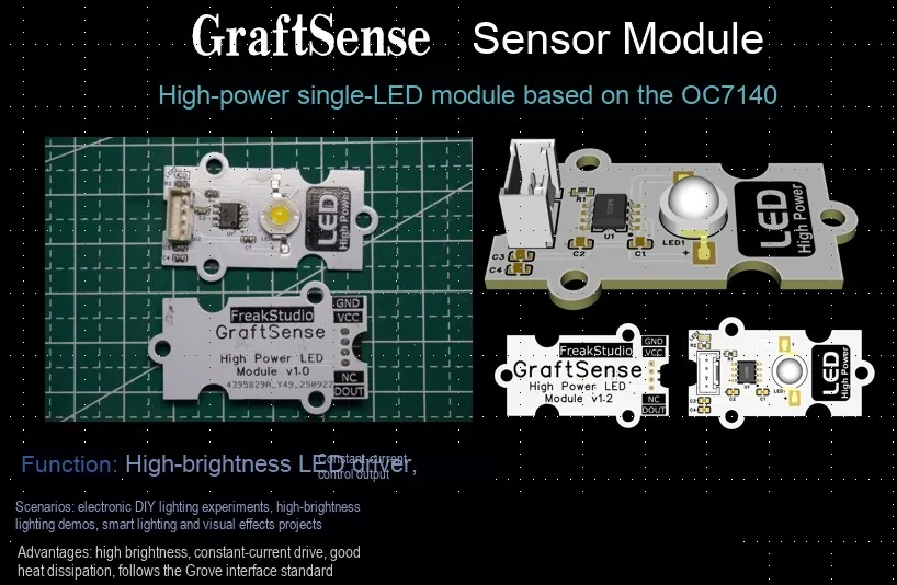
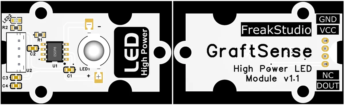
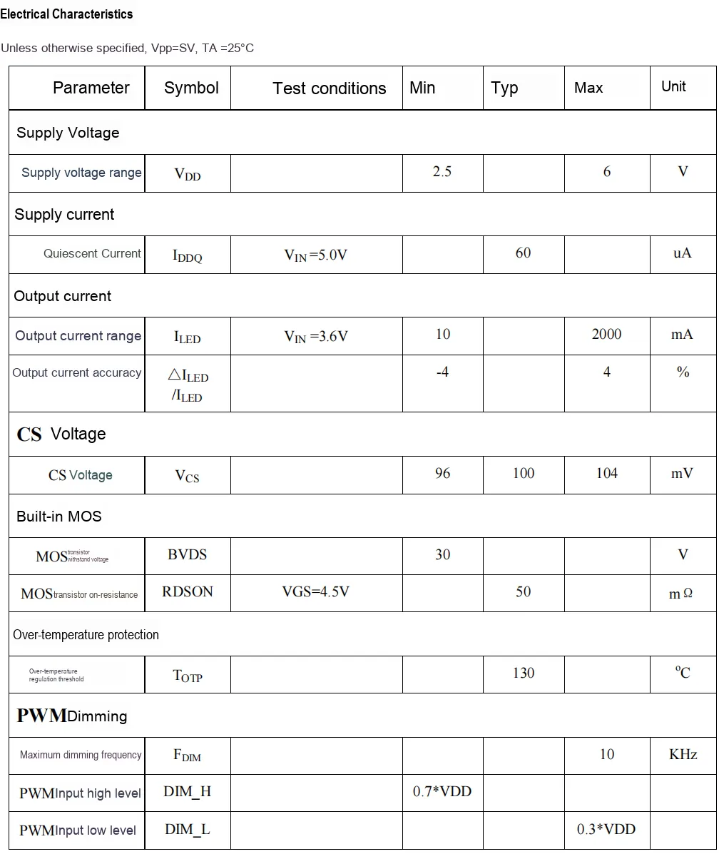
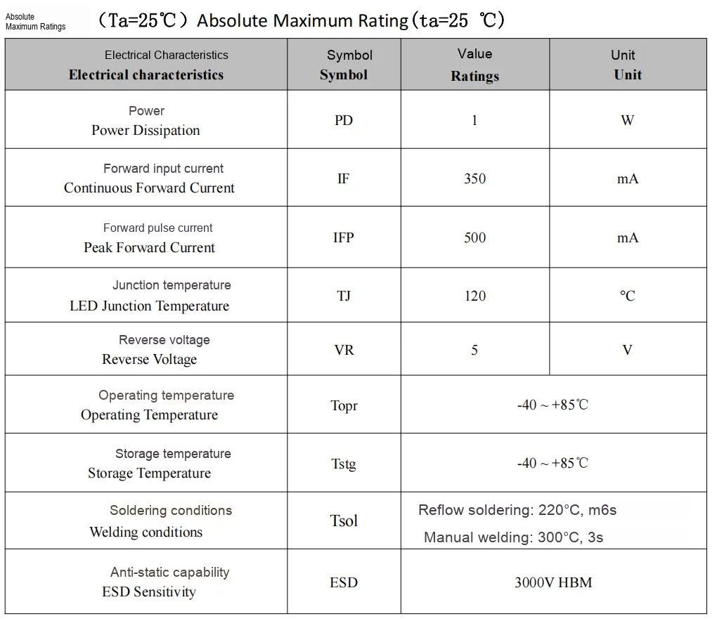
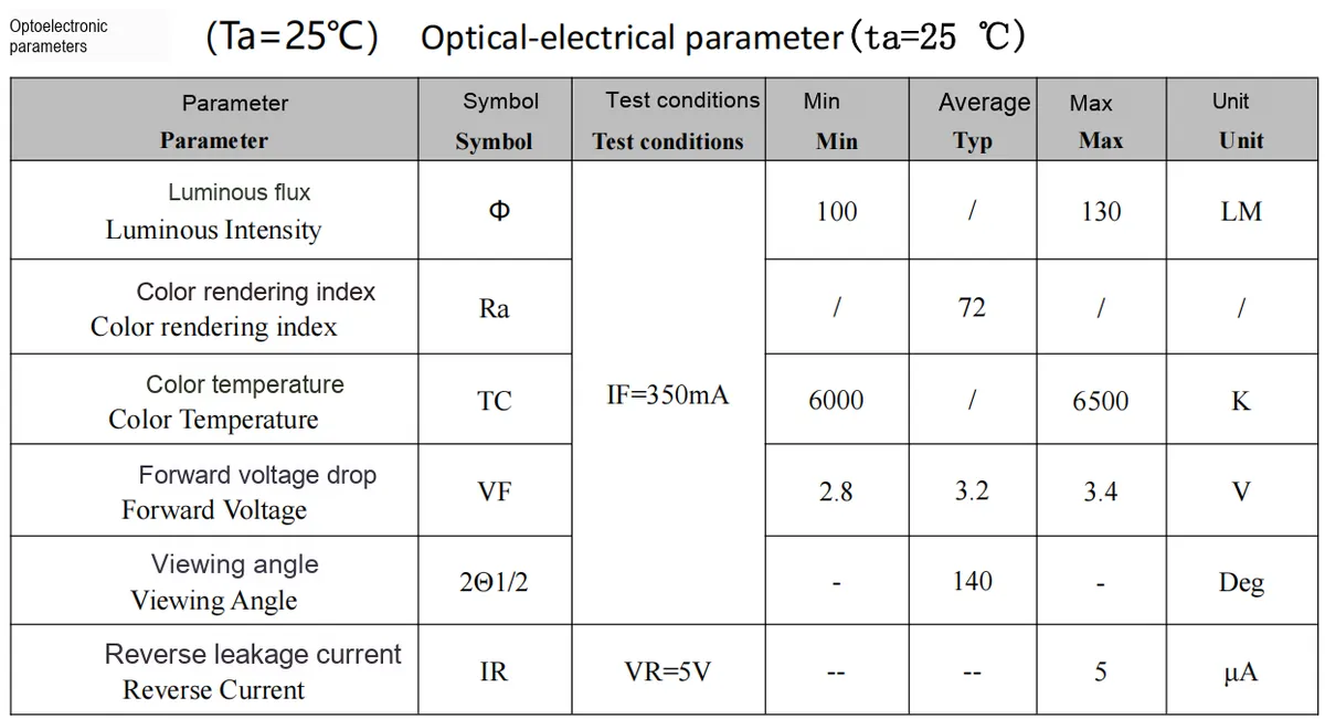
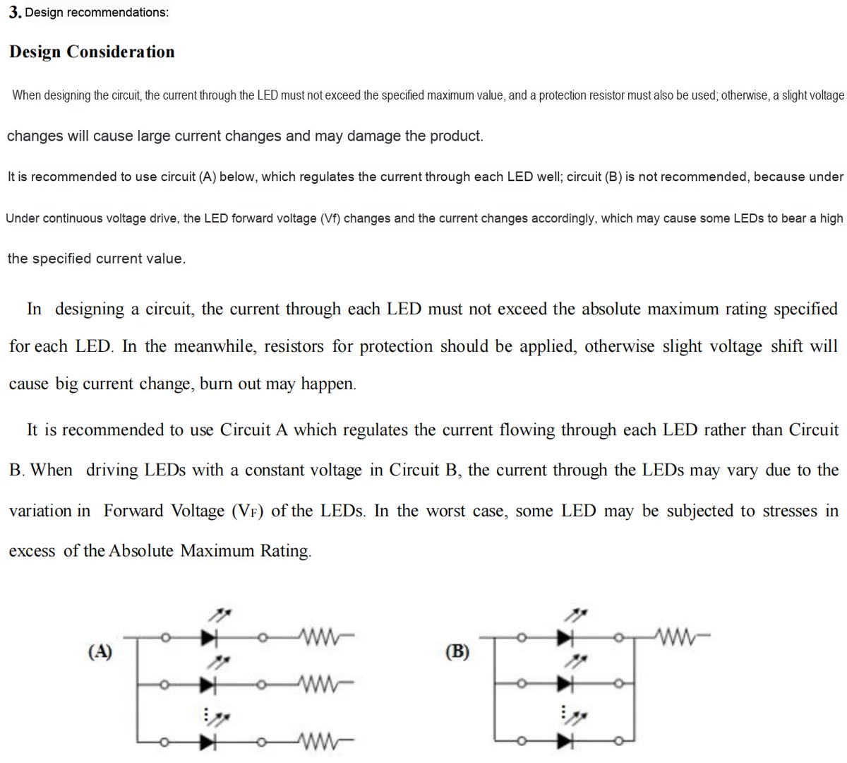
High-power single-chip LED module based on OC7140 with its core adopting OC7140 a linear step-down PWM dimming LED constant current driver (supporting 2.5-6V operating voltage, 10mA-2000mA output current adjustment, up to 10KHz PWM dimming and over-temperature protection), paired with XL-HD6070UWC-A2-BD 1W high-power spherical white LED chip (140° light emitting angle, high brightness, compliant with RoHS standards). This module has an output current of approximately 0.333mA, is suitable for scenarios such as LED lighting and flashlights, and provides an efficient and controllable constant current driving and dimming solution for high-power LED.
II. Introduction to Main Chips
This module mainly relies on OC7140 a linear step-down with PWM dimming function LED constant current driver and XL-HD6070UWC-A2-BD high-power dome-type white light light-emitting diode.
2.1 Chip Overview
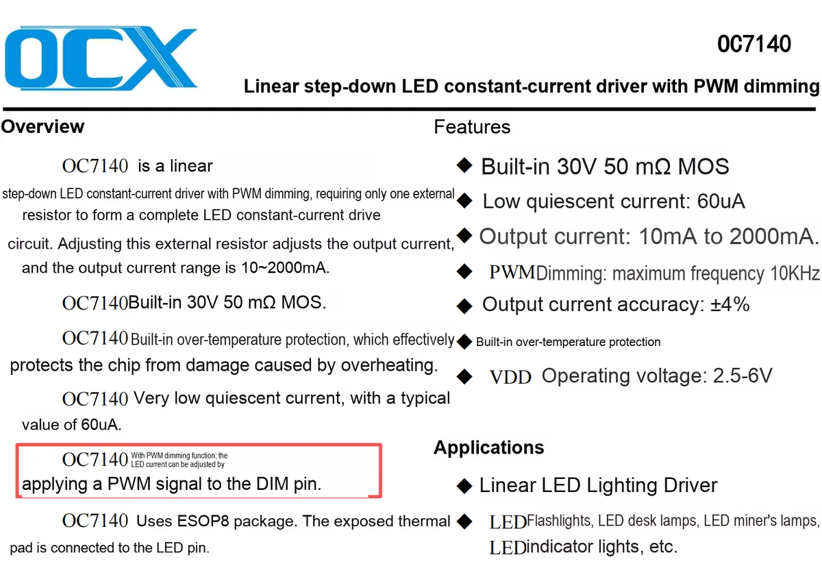
2.1.1 OC7140 LED Constant Current Driver
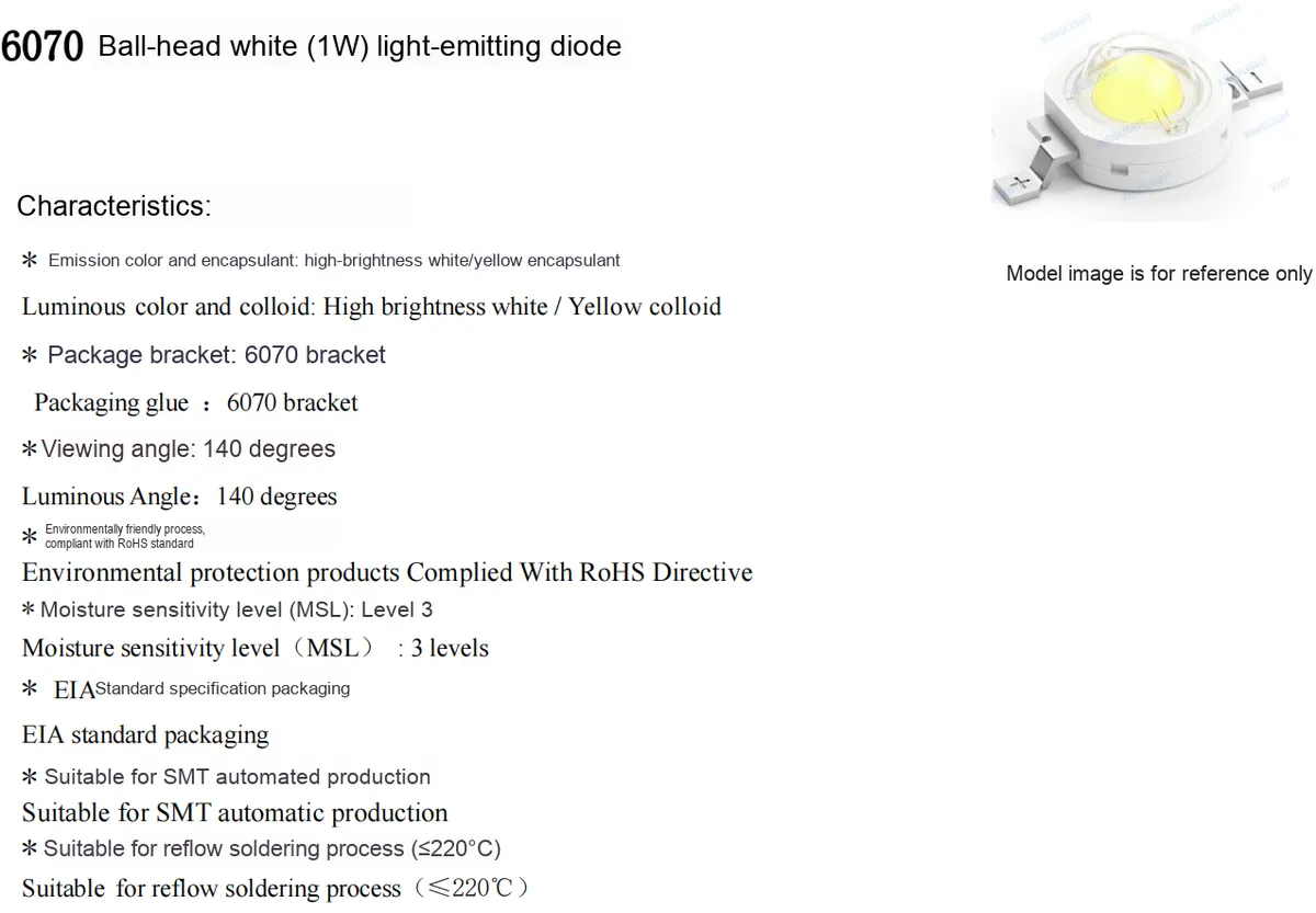
2.1.2 XL-HD6070UWC-A2-BD High-power dome white light emitting diode
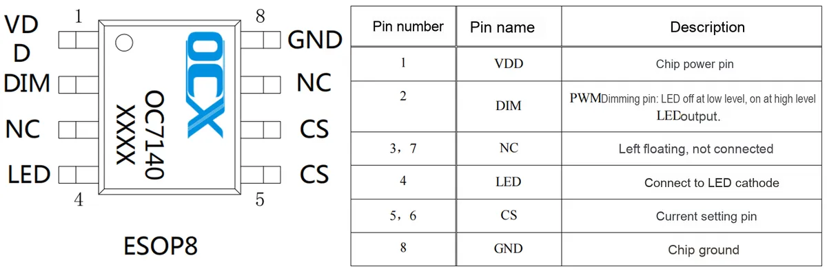
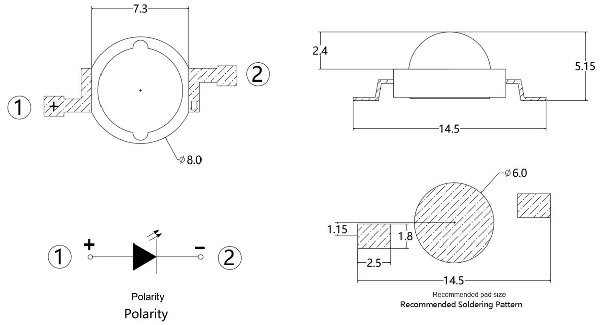
2.2 Pin Definition
2.2.1 OC7140 LED Constant Current Driver
2.2.2 XL-HD6070UWC-A2-BD High-power dome white light emitting diode
2.3 Functional Block Diagram
2.3.1 OC7140 LED Constant Current Driver
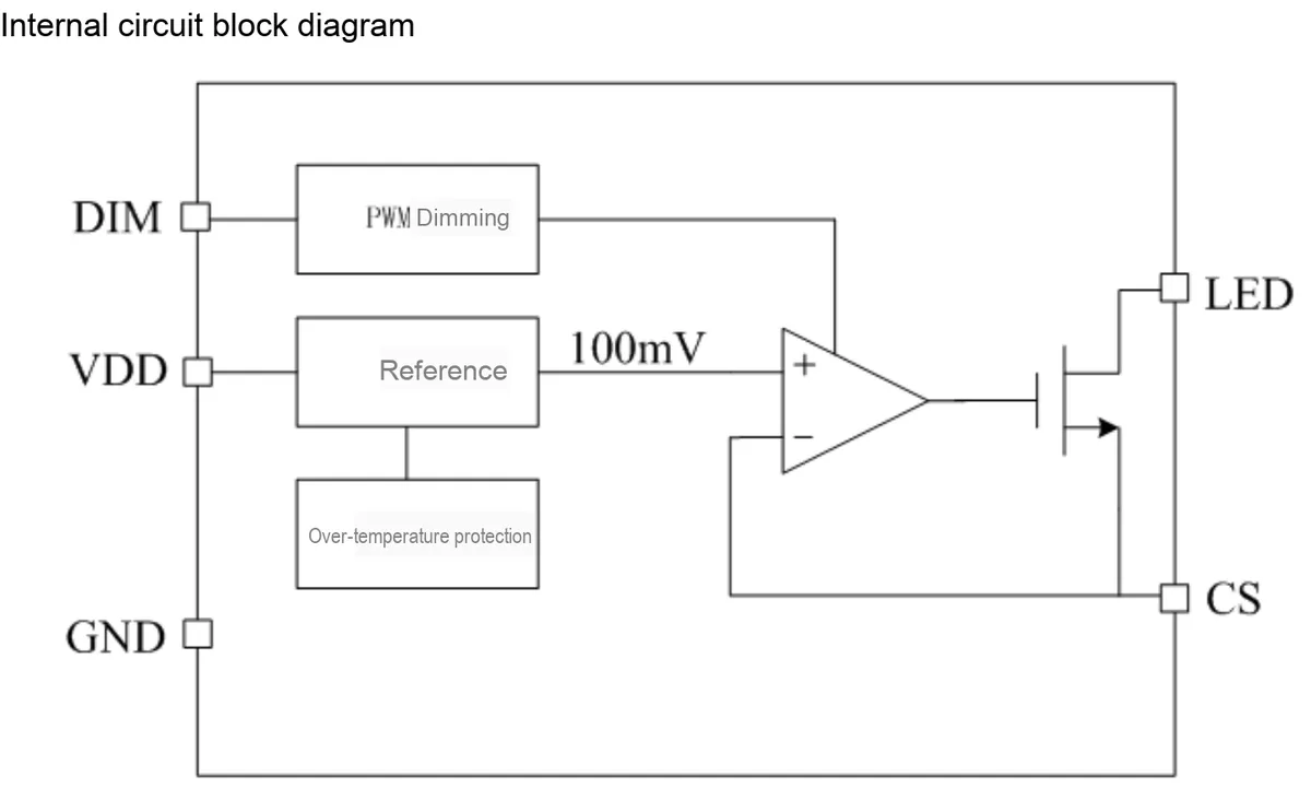
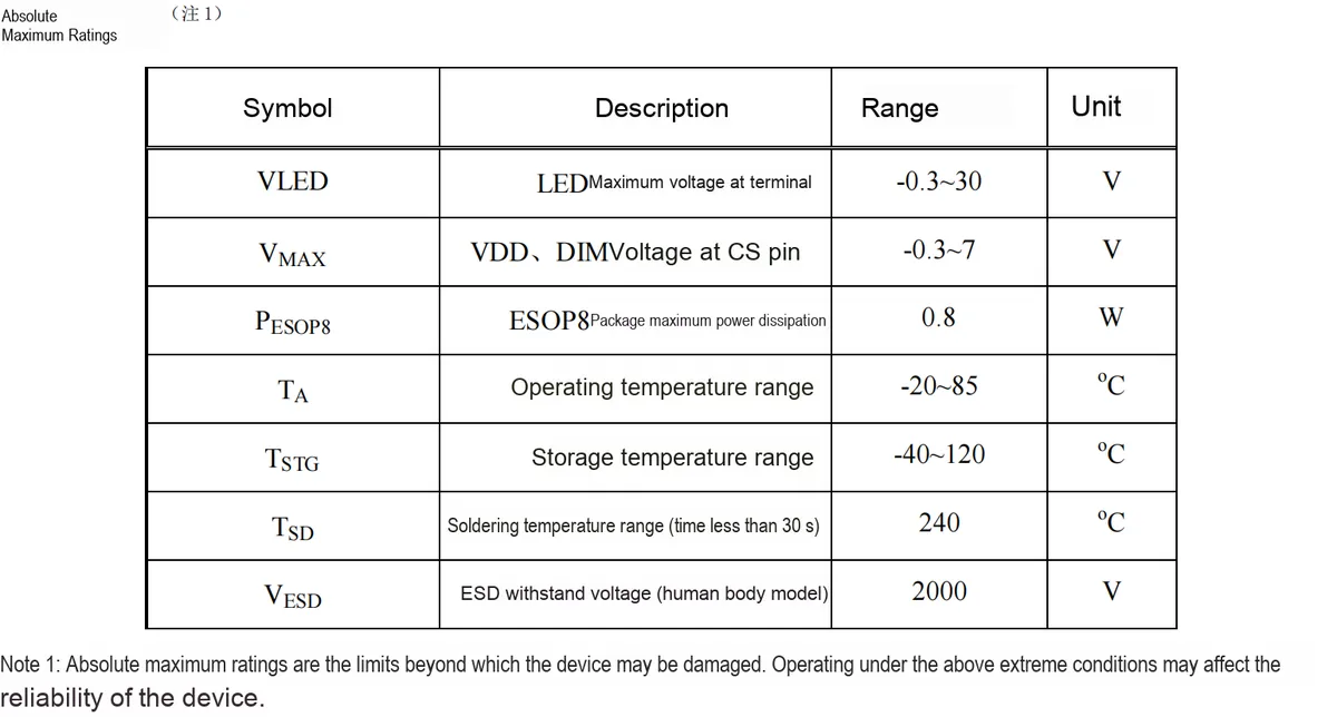
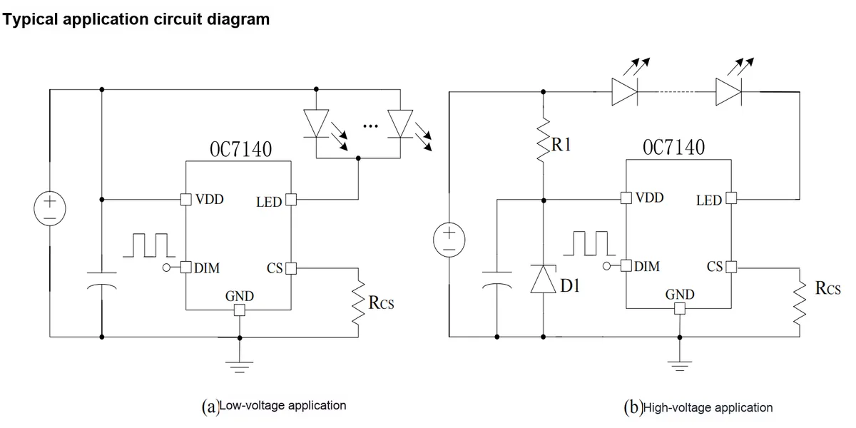
OC7140 The functional block diagram mainly consists of the following modules and pins, which work together to implement the linear step-down with PWM dimming LED constant current drive function:
- Power Supply and Pins :
VDD: Chip power supply input (operating voltage: 2.5-6V), which supplies power to the entire module;GND: Ground pin;DIM:PWMdimming signal input pin;LED: High-power LED connection pin, outputting constant-current drive current;CS: Current sense pin, which is used to feed back current information to realize constant current control.
- Core Function Module:
PWMDimming Module: Receives theDIMpinPWMsignal to adjust theLEDbrightness, and supports a maximumPWMfrequency of 10KHz.- Reference module: generates a 100mV reference voltage which serves as the reference threshold for current control.
- Over temperature protection module: monitors the chip temperature in real time, and triggers protection if overheating occurs to prevent the chip from being damaged by high temperature.
- Operational Amplifier +
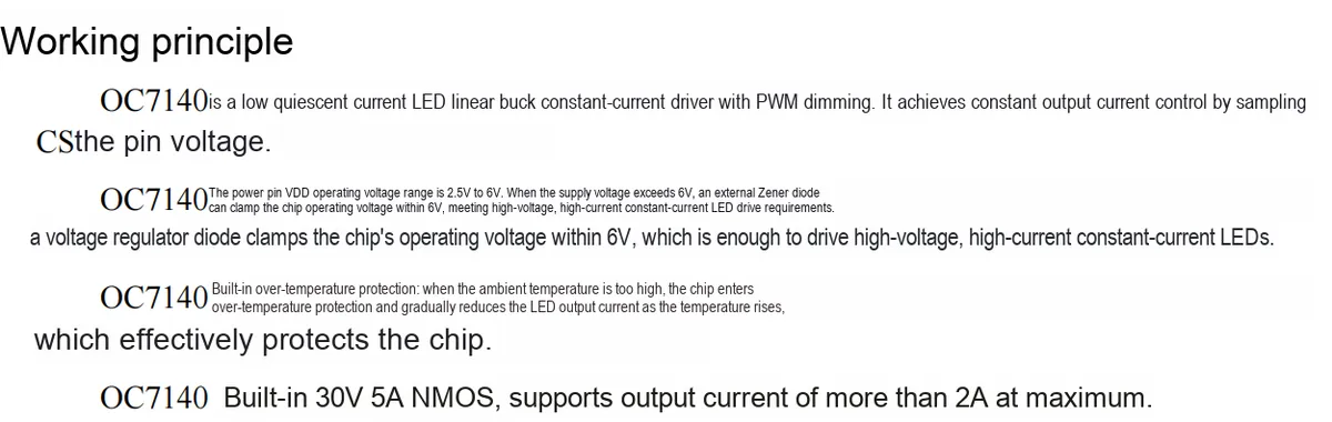
MOSTransistor: The operational amplifier compares the detection voltage at theCSpin with the 100mV reference voltage, and dynamically controls the conduction state of the built-inMOStransistor, so as to stabilize the output current ofLED(achieving constant current drive with a current range of 10mA~2000mA and an accuracy of ±4%).
2.3.2 XL-HD6070UWC-A2-BD High-power dome-type white light emitting diode
None.
2.4 Performance Parameters
2.4.1 OC7140 LED Constant Current Driver
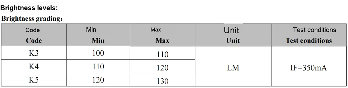
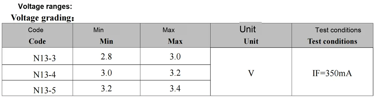
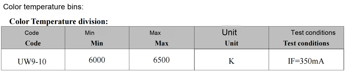
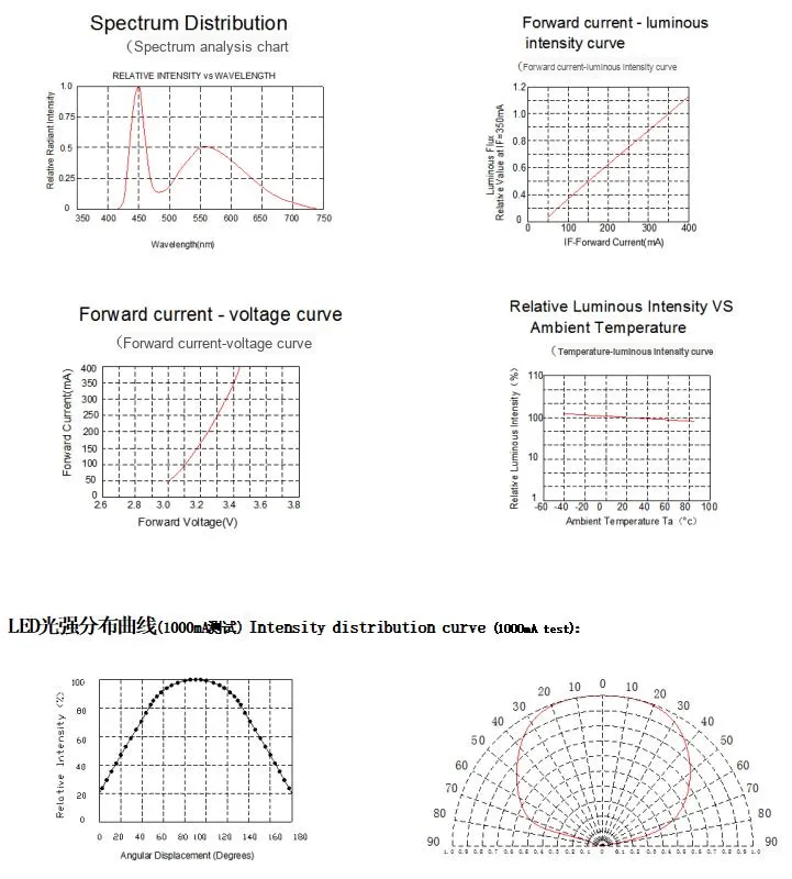
2.4.2 XL-HD6070UWC-A2-BD High-power dome white light emitting diode
2.5 Reference Circuit
2.5.1 OC7140 LED Constant Current Driver
2.5.2 XL-HD6070UWC-A2-BD High-power dome white light emitting diode
2.6 Chip Configuration
2.6.1 OC7140 LED Constant Current Driver
2.6.2 XL-HD6070UWC-A2-BD High-power dome-type white light emitting diode
None.
2.7 Communication Interfaces and Related Protocols
None.
2.8 PCB Routing Precautions
2.8.1 OC7140 LED Constant Current Driver
2.8.2 XL-HD6070UWC-A2-BD High-power dome-type white light emitting diode

III. Instructions for Circuit Engineering and Module Usage
3.1 Circuit Source Engineering
To obtain the source code of the circuit, please follow the official account [Freak Embedded]
3.2 Module Usage Instructions
The schematic diagram of this module is shown below:
SCH_High-Power Single-LED Module Based on OC7140_v1.1_2025-11-24.pdf 2.5 MB
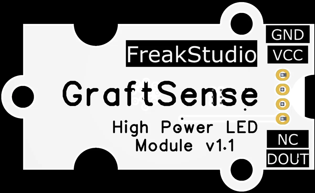
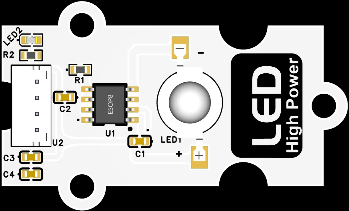
This module provides a digital interface DOUT: connect the module's DOUT interface to the MCU 's PWM output terminal, so that the MCU can output a PWM signal with adjustable duty cycle to the PWM signal to the OC7140 ' s DIM pin.
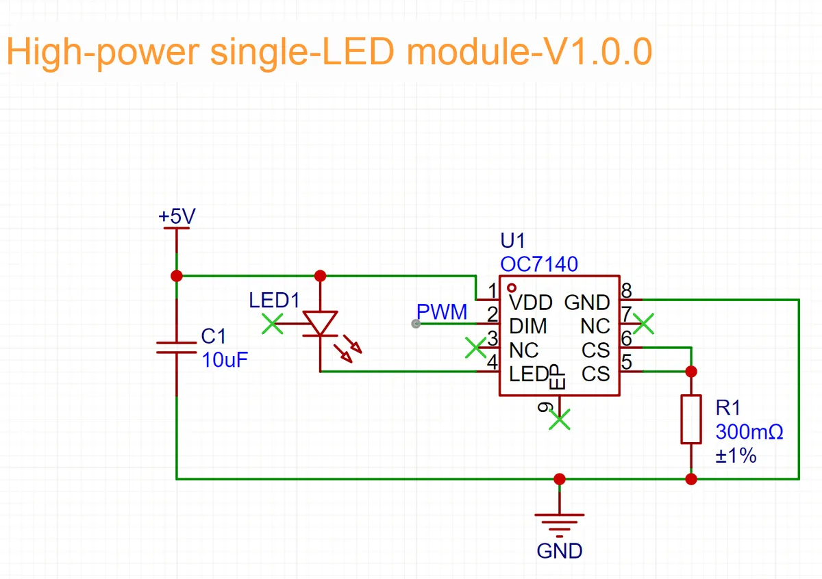
As can be seen, OC7140 's DIM pin receives the PWM signal, the internal PWM dimming module will dynamically adjust the "effective conduction time" of the LED driving current according to the duty cycle:
- The higher the duty cycle,
the longer the effective on-time of theLED drive current, the larger the average current, and the higher the brightness of theLED; - The lower the duty cycle,
the shorter the effective on-time of theLED drive current, the smaller the average current,and the lower theLED brightness.
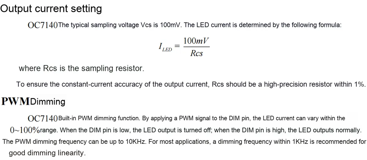
In the circuit, R1 serves as the current sensing resistor. According to the current formula of OC7140 I= 100mv/R1, the base current is approximately 0.333 mA. PWM dimming, based on this base current, adjusts the average current by varying the duty cycle to ultimately achieve continuous brightness regulation.
3.3 Application Experiment
Here, we use the GraftPort-RP2040 development board for testing, and connect the high-power single-LED module based on OC7140 to communicate with the main controller via the DIO interface.
Here, we first use the HY2.0-4P cable to connect the module to the GraftPort-RP2040 development board's DIO0 interface:
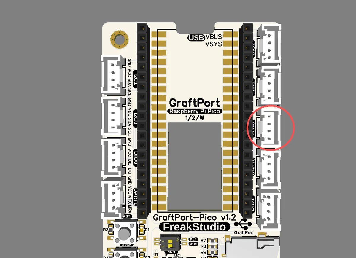
The module connections are shown in the following table:
Development Board Pins | Module Pins | Description |
Pin 6 |
| PWM output / level output pins on the MCU |
Pin 7 |
| - |
Here, we need to search for relevant driver packages on uPyPI: https://upypi.net/zh/
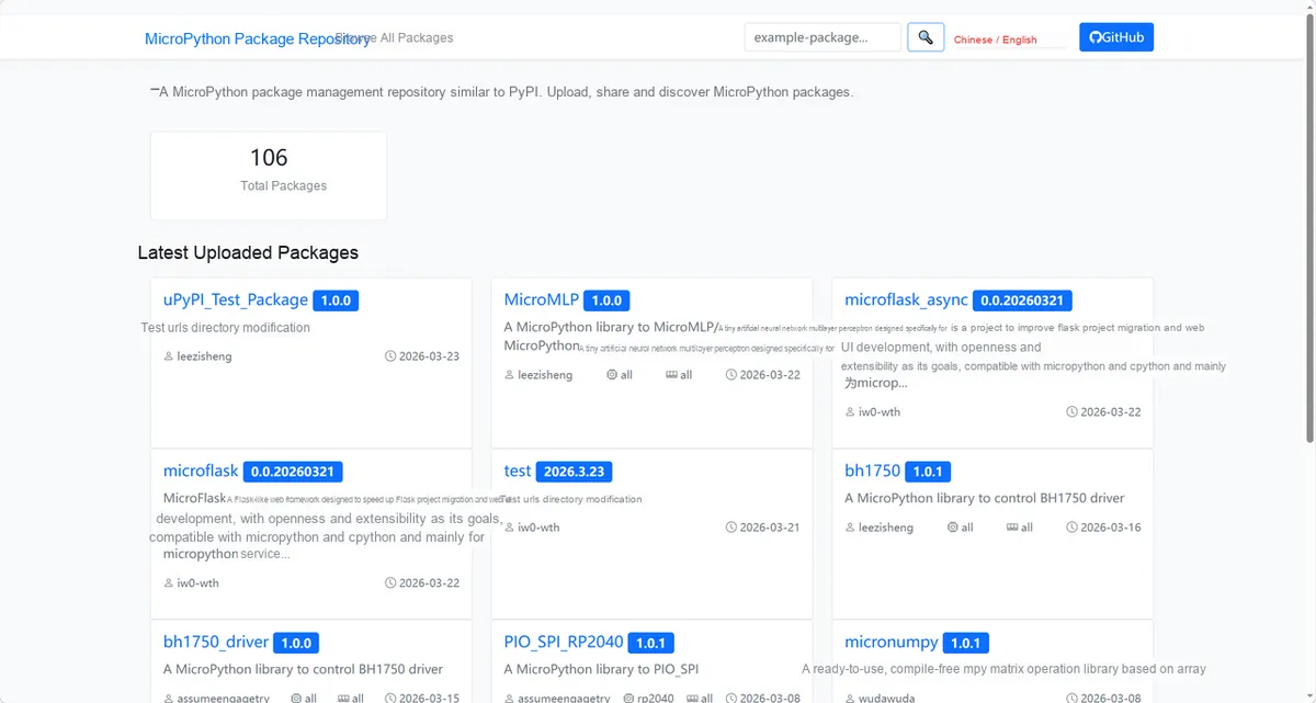
Enter led_single_driver to search, and the following will be displayed:

Click to copy the local installation command:
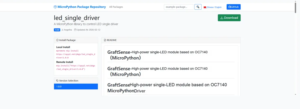
Here, we can use the mip tool to import module driver library code. Below are the usage commands for the mpremote tool:
mpremote mip install github:FreakStudioCN/GraftSense-Drivers-MicroPython/lighting/led_single_driverImport the high-power single LED bead driver code based on OC7140 - MicroPython driver code, then copy the following main.py code into our project:
# Python env   : MicroPython v1.23.0
# -*- coding: utf-8 -*-
# @Time    : 2025/8/25 11:53 AM
# @Author  : 缪贵成
# @File    : main.py
# @Description : High-power single LED driver test file, including on/off, toggle, and PWM brightness control

# ======================================== Import Modules =========================================

# Import time-related modules
import time
# Import third-party modules
from led_single_power import PowerLED

# ======================================== Global Variables =============================================

# ======================================== Functions =============================================

# ======================================== Custom Classes =============================================

# ======================================== Initialization configuration ===========================================

# Power-on delay of 3 s
time.sleep(3)
print("FreakStudio: Test high-power LED lights")

# Create an instance using pin GP14
led = PowerLED(pin=14, pwm_freq=1000)

# ======================================== Main Program ==============================================

# Turn on the LED
try:
    led.on()
    print("LED turned ON.")
    time.sleep(4)
except RuntimeError as e:
    print("Error turning LED ON:", e)

# Turn off the LED
try:
    led.off()
    print("LED turned OFF.")
    time.sleep(4)
except RuntimeError as e:
    print("Error turning LED OFF:", e)

# Toggle the LED state
try:
    led.toggle()
    print("LED toggled. Current state:", "ON" if led.get_state() else "OFF")
    time.sleep(1)
except RuntimeError as e:
    print("Error toggling LED:", e)

# Set brightness for gradual dimming
try:
    for duty in range(0, 1024, 2):
        led.set_brightness(duty)
        print(f"LED brightness set to {duty}/1023. Current state:", "ON" if led.get_state() else "OFF")
        time.sleep(0.5)
except (ValueError, RuntimeError) as e:
    print("Error setting brightness:", e)

# Finally turn off the LED
try:
    led.off()
    print("LED turned OFF at the end of test.")
except RuntimeError as e:
    print("Error turning LED OFF at the end:", e)

print(" PowerLED Test End ")
To flash the code, open a terminal and use the mpremote tool to connect to the main controller; the output is as follows:
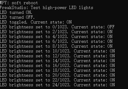
It can be seen that the lights will glow sequentially and change their brightness following the process in the code.
IV. Drivers
led_single_driver.zip 10 KB
5. BOM & Recommended Alternative Parts
None.
VI. Revision History
Document Version | Date of Revision | Modifier | Revised Content |
v1.0 | 2025-11-24 | Li Zisheng | Initialize the document The BOM sheet has not been finally checked, the driver has not been re-verified, and the 3.3 application experiment Not yet specified. |
v1.1 | 2025-12-29 | Li Zisheng | Added application experiments and production files |
v1.2 | 2025-12-31 | Xin Ruili | Create an open version of the document based on the internal document version v1.1. |
v1.3 | 2026-03-29 | Xin Ruili | Modified the application experiment section. |
VII. Relevant Materials
7.1 Chip Datasheet
C42458854_Light Emitting Diode-LED_XL-HD6070UWC-A2-BD_Datasheet_WJ1763628.PDF 1.3 MB
C842736_LED Driver_OC7140_Datasheet_WJ247205.PDF 321 KB
7.2 Unique Icons for PCB Silk Screen