Contents
- I. Module Introduction
- II. Introduction to Main Chips
- 2.1 Chip Overview
- 2.2 Pin Definition
- 2.3 Functional Block Diagram
- 2.4 Performance Parameters
- 2.5 Reference Circuit
- 2.6 Chip Configuration
- 2.7 Communication Interfaces and Related Protocols
- 2.8 PCB Routing Precautions
- III. Instructions for Circuit Engineering and Module Usage
- 3.1 Circuit Source Engineering
- 3.2 Module Usage Instructions
- 3.3 Application Experiment
- IV. Drivers
- 5. BOM & Recommended Alternative Parts
- VI. Revision History
- VII. Relevant Materials
- 7.1 Chip Datasheet
- 7.2 Unique Icons for PCB Silk Screen
I. Module Introduction
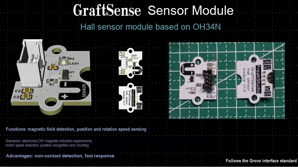
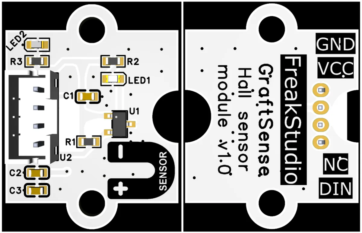
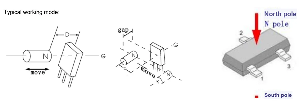
Hall Sensor Module Based on OH34N takes OH34N as the core device: OH34N is a unipolar Hall switch with SOT23-3 package, which integrates internal circuits such as a voltage regulator and a Hall generator, supports N -pole triggering, operates at a temperature range of -40~125℃, features wide voltage tolerance and fast switching speed, and is suitable for contactless switch applications.The module circuit is equipped with C2 / C3 power filter capacitors for stable power supply. R1 (4.7kΩ), serving as a pull-up resistor, matches the open-collector output of OH34N. C1 is used for signal filtering, and LED1 / LED2 acts as status indicators. When a magnetic field approaches, OH34N converts the magnetic field signal into a digital level, which is transmitted to DIN interface and then to MCU. It can realize functions such as position detection and magnetic field sensing, and adapt to the sensing requirements of scenarios including motors and home appliance control.
II. Introduction to Main Chips
2.1 Chip Overview
2.2 Pin Definition
2.3 Functional Block Diagram
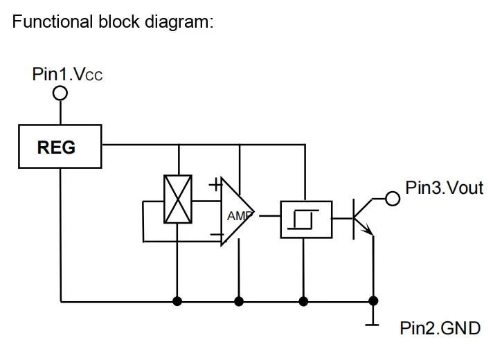
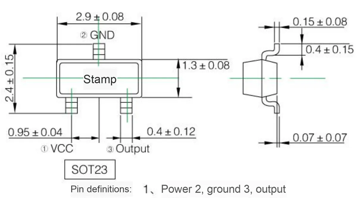
Pin1 (Vcc) receives the input power, which is first regulated by the REG voltage regulator to provide stable power supply for subsequent modules; the Hall generator senses magnetic field changes to generate a weak electrical signal, which is amplified by the AMP amplifier, then sent to the Schmitt trigger for level shaping and debounce processing, and finally outputs a digital signal through the open-collector output stage from Pin3 (Vout);Pin2 serves as the ground terminal (GND) of the entire circuit, realizing a complete functional chain of "magnetic field signal → electrical signal → amplification & shaping → digital output" as a whole.
2.4 Performance Parameters

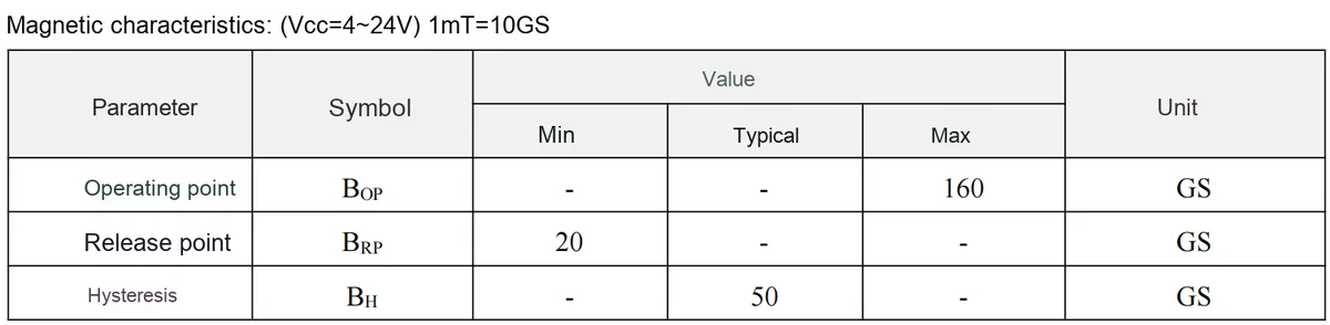
2.5 Reference Circuit
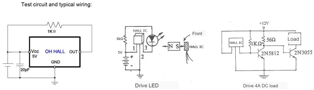
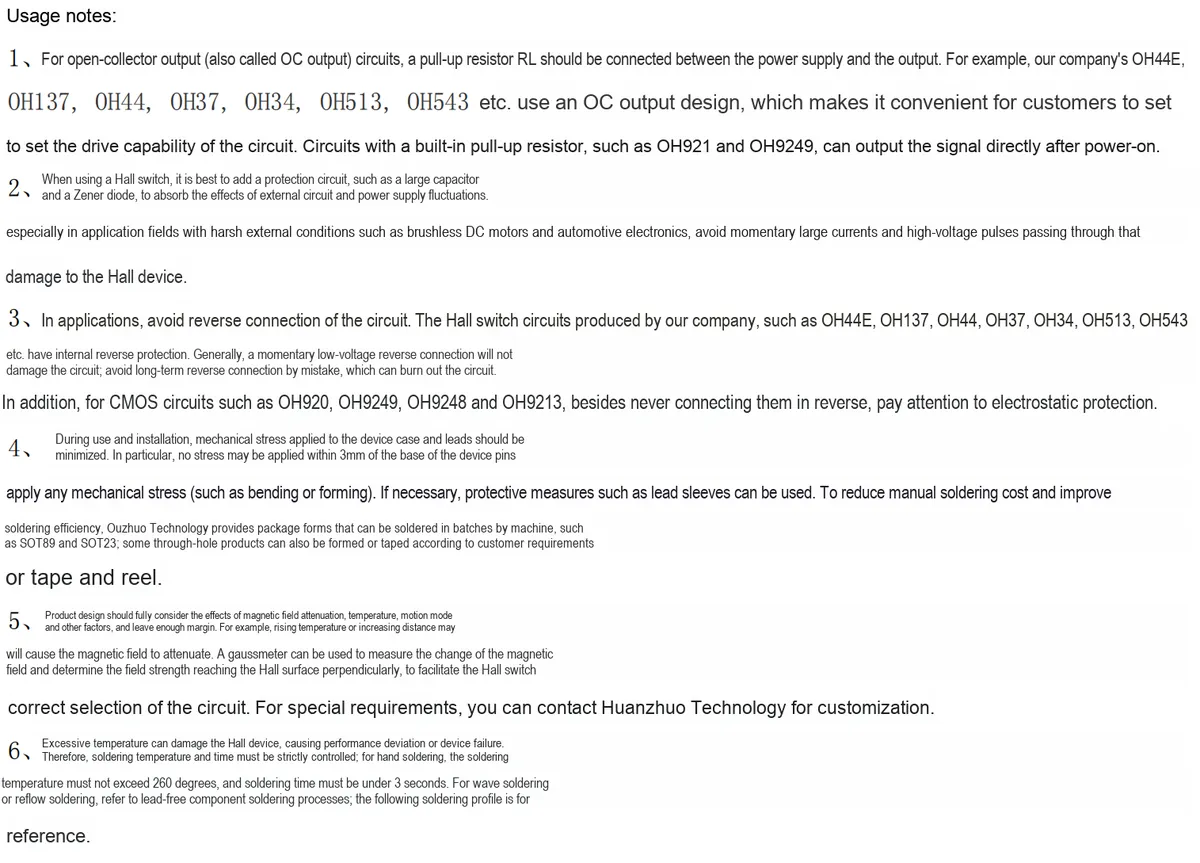
This section covers OH34N Hall switch's three typical wiring configurations (basic test, LED driving, 4A DC load driving) as well as 6 usage precautions:
OCoutput requires an external pull-up resistor;- Built-in protection circuits such as capacitors and voltage regulators for harsh environments;
- Avoid reverse connection of the circuit; some models feature reverse protection but do not leave them reversely connected for a long time,
CMOStypes require anti-static protection; - Installation reduces mechanical stress on device pins;
- The design shall take into account factors such as magnetic field attenuation and temperature;
- The soldering temperature shall not exceed 260℃, the duration shall be less than 3 seconds, and refer to the lead-free process.
2.6 Chip Configuration
None.
2.7 Communication Interfaces and Related Protocols
None.
2.8 PCB Routing Precautions
None.
III. Instructions for Circuit Engineering and Module Usage
3.1 Circuit Source Engineering
To obtain the source code of the circuit, please follow the official account [Freak Embedded]
3.2 Module Usage Instructions
The schematic diagram of this module is as follows:
SCH_Hall Sensor Module Based on OH34N_v1.0_2025-11-26.pdf 2.1 MB
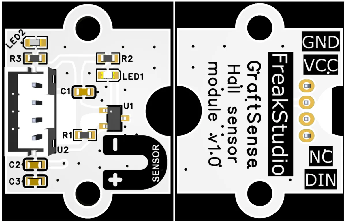
This module provides a DIN interface, which can be connected to the MCU 's GPIO interface. It should be noted the signal characteristics of this interface — the OH34N Hall chip will only trigger a falling edge transition of the output signal (i. e., the output level switches from high to low) when the magnetic field changes (such as when the N pole approaches or moves away from the sensor); if the magnetic field remains stable, the OH34N Hall chip will not continuously output a signal through the DIN interface.
It is recommended to configure the MCU corresponding GPIO to the falling edge interrupt mode during use, so as to accurately capture the falling edge signal triggered by magnetic field changes and avoid missing sensing events.
3.3 Application Experiment
Here, we use the GraftPort-RP2040 development board for testing, and the OH34N-based Hall sensor module communicates with the main controller via the DIO interface.
Here, we first use the HY2.0-4P cable to connect the module to the GraftPort-RP2040 development board's DIO0 interface:
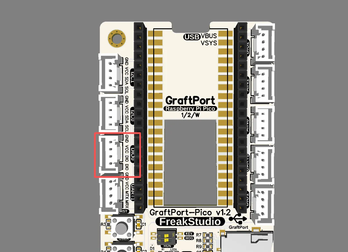
The module connections are shown in the following table:
Development Board Pins | Module Pins | Description |
Pin 6 |
| Level signal input pin of the Hall sensor |
Pin 7 |
| - |
Here, we need to search for relevant driver packages on uPyPI: https://upypi.net/zh/
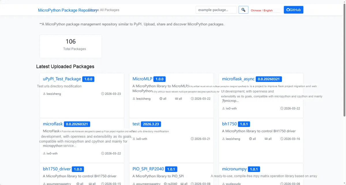
Enter hall_sensor_oh34n_driver to search, and the following will be displayed:
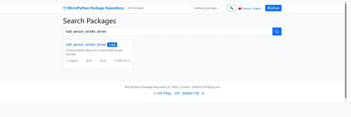
Click to copy the local installation command:
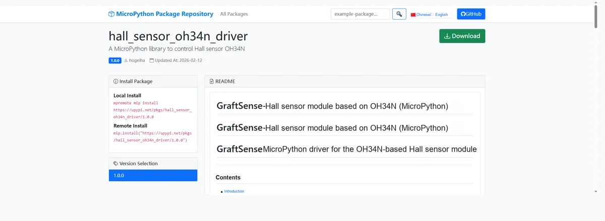
Here, we can use the mip tool to import module driver library code. Below are the usage commands for the mpremote tool:
mpremote mip install github:FreakStudioCN/GraftSense-Drivers-MicroPython/sensors/hall_sensor_oh34n_driverImport the OH34N Digital Hall Sensor - MicroPython driver code, then copy the following main.py code into our project:
# Python env   : MicroPython v1.23.0
# -*- coding: utf-8 -*-
# @Time    : 2025/8/25 9:48 AM
# @Author  : 缪贵成
# @File    : main.py
# @Description : Hall sensor driver test file (digital)

# ======================================== Import Related Modules ==========================================

import time
from hall_sensor_oh34n import HallSensorOH34N

# ======================================== Global Variables =============================================

# Debounce flag
flag = False
# Last trigger time
last_time = 0
# Debounce interval 200ms
DEBOUNCE_MS = 200

# ======================================== Functions =============================================

def hall_callback() -> None:
    """
        Interrupt callback function of the Hall sensor.
        Triggered when a magnetic field change is detected, and prints a prompt message.

    Notes:
        This callback function is triggered by an IRQ interrupt and scheduled via micropython.schedule.
        Avoid adding time-consuming or blocking operations in the callback.

    ==========================================

        Interrupt callback for Hall sensor.
        Triggered when magnetic field change is detected, prints notification.

    Notes:
        This callback is triggered by IRQ and scheduled via micropython.schedule.
        Avoid long-running or blocking operations in the callback.
    """
    global flag, last_time
    now = time.ticks_ms()
    if time.ticks_diff(now, last_time) > DEBOUNCE_MS:
        flag = True
        last_time = now

# ======================================== Custom Classes ==============================================

# ======================================== Initialization Configuration ============================================

# Power-on delay
time.sleep(3)
print("FreakStudio: Hall Sensor OH34N Test Start ")

# Initialize the Hall sensor (pin GP22)
sensor = HallSensorOH34N(pin=6, callback=hall_callback)

# Enable interrupt detection
sensor.enable()
print("Interrupt detection enabled.")

# ======================================== Main Program ===============================================

try:
    while True:
        if flag:
            print("Callback: Magnetic field detected!")
            flag = False
        state = sensor.read()
        print(f"Magnetic field detected: {state}")
        time.sleep(1)
except KeyboardInterrupt:
    print("Test stopped by user.")
    sensor.disable()
    print("Interrupt detection disabled.")
To flash the code, open a terminal and use the mpremote tool to connect to the main controller; the output is as follows:
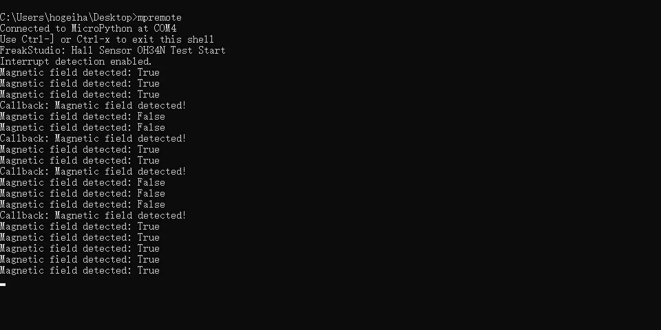
It can be seen that when we move a magnet back and forth over the sensor module, a callback will be triggered and the result will be printed to the terminal.
IV. Drivers
hall_sensor_oh34n_driver.zip 11 KB
5. BOM & Recommended Alternative Parts
None.
VI. Revision History
Document Version | Date of Revision | Modifier | Revised Content |
v1.0 | 2025-11-26 | Li Zisheng | Initialize the document The BOM sheet has not been finally checked, the driver has not been re-verified, and the 3.3 application experiment Not yet specified. |
v1.1 | 2025-12-29 | Li Zisheng | Added application experiments and production files |
v1.2 | 2025-12-31 | Xin Ruili | Create an open version of the document based on the internal document version v1.1. |
v1.3 | 2026-03-29 | Xin Ruili | Modified the application experiment section |
VII. Relevant Materials
7.1 Chip Datasheet
C90403_Hall Switch_OH34N_Datasheet_WJ298082.PDF 321 KB
7.2 Unique Icons for PCB Silk Screen