
Contents
- Introduction
- I. Module Introduction
- 2. Introduction to Main Chips
- 2.1 Chip Overview
- 2.2 Pin Definition
- 2.4 Performance Parameters
- 2.5 Communication Interfaces and Related Protocols
- 2.6 Register Definition
- III. Circuit Engineering
- 3.1 Circuit Source Engineering
- 3.2 Module Usage Instructions
- 3.3 Application Experiment
- 4. Drivers
- 5. BOM & Recommended Alternative Parts
- VI. Revision History
- VII. Relevant Materials
Introduction
In scenarios such as frost formation on refrigerator evaporators, ice accretion on fan blades, and road icing, the presence of frost and ice directly affects equipment efficiency and operational safety. However, traditional frost and ice detection solutions have long been plagued by the industry pain points of "extensive control, high error rate, and high maintenance costs — refrigerators generally adopt timed defrosting, which forces defrosting to start regardless of the amount of frost, wasting energy and failing to cope with abnormal thickening of the frost layer; in industrial scenarios, resistive and optical detection solutions are vulnerable to interference from contamination and condensation, have a high error rate, and are difficult to operate stably for a long time.Minyuan FDE Sensor Frost & Ice Sensor adopts capacitive non-contact sensing technology to realize accurate and quantitative frost/ice detection, providing reliable frost and ice sensing solutions for various scenarios.
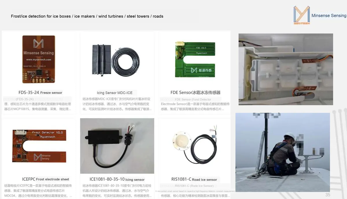
- Refrigerator / Home Appliance Scenario: Timed defrost cannot be adjusted according to the actual frost accumulation: it either wastes excessive power due to over-defrosting, or leads to reduced cooling efficiency due to untimely defrost. The method of indirectly judging frost formation via temperature sensors is susceptible to ambient temperature, cannot quantify the frost layer thickness, and thus has poor control accuracy.
- Industrial / Outdoor Scenarios: Traditional resistive sensors are prone to corrosion and contamination by frost and condensation, resulting in a short service life; optical solutions are susceptible to obstruction and reflective interference, leading to a high error rate; in addition, most of them can only make qualitative judgments, and are unable to quantify the thickness of frost / ice layers, making it difficult to support refined control and early warning.
The advent of the FDE Sensor, leveraging capacitive sensing technology, has filled the gaps in these solutions.
Core Advantages of FDE Sensor: Precise, Reliable and Easy-to-Integrate Frost Detection
- ✅ Non-contact detection, quantitative frost thickness measurement for more precise control: The FDE Sensor is based on the capacitive sensing principle and integrates the high-precision differential capacitive sensing chip MDC04. It determines the frost thickness by detecting changes in dielectric constant, where the frost thickness is directly proportional to the capacitance value. It can detect frost layers with a thickness of ≤10mm and achieves a resolution of 1mm. Equipped with a built-in MCU detection processor, it effectively filters out interferences from temperature, electromagnetism and other factors, quantifies frost accumulation, and upgrades defrosting control from "timed extensive mode" to "on-demand precision mode", which not only improves equipment efficiency but also reduces energy consumption.
- ✅ Strong anti-interference performance plus wide-temperature durability, ensuring stable operation even in complex environments: The sensor supports a wide temperature Scope of Work from -40℃ to + 85℃, adapting to harsh environments such as low-temperature conditions in refrigerators and outdoor industrial equipment; its non-contact design eliminates direct contact with frost, fundamentally avoiding corrosion and contamination issues, and it can maintain stable detection performance over long-term use without frequent maintenance.
- ✅ Low power consumption + easy installation, adaptable to multiple scenarios: Its operating power consumption is only 4.5mA@3.3V, with a supply voltage ranging from 2V to 5.5V, compatible with battery or device power supply; the compact sensor structure can be directly mounted closely to the fins of the refrigerator evaporator without complex modification; equipped with a UART communication interface, it can be easily integrated into various devices, providing a convenient frost detection solution for home appliances and industrial equipment.
It can be used for:
- Refrigerator / Ice Maker Scenario: The "Precision Commander" of Intelligent Defrosting
- In devices such as refrigerator evaporators and ice makers, the FDE Sensor can be mounted closely to the fins to detect frost thickness in real time. When the frost layer reaches the set threshold, it can trigger the defrosting program to achieve on-demand defrosting, which avoids the energy waste caused by traditional timed defrosting, prevents excessive frost layer from impairing refrigeration efficiency, and enables the refrigerator to operate more energy-efficiently with more stable refrigeration performance.
- Industrial Fans / Transmission Tower Scenarios: The "Frost Sentinel" for Equipment Safety
- In outdoor equipment such as fan blades and power transmission towers, sensors can monitor ice/frost accretion in real time and issue early warnings in a timely manner to prevent equipment damage and line failures caused by excessive frost and ice. Its non-contact design is immune to outdoor condensation and temperature fluctuations, enabling long-term stable operation and providing all-weather monitoring for the safe operation of industrial equipment.
- Road / Outdoor Scenarios: A Reliable Sensing Unit for Icing Warning
- In the scenario of road ice detection, the FDE Sensor can be used to monitor the thickness of ice layers on road surfaces and provide data support for road safety early warning. Free from the interference of road surface impurities and light reflection, the sensor can accurately identify ice formation, helping traffic management authorities take anti-skid measures in a timely manner to ensure safe road traffic.
I. Module Introduction

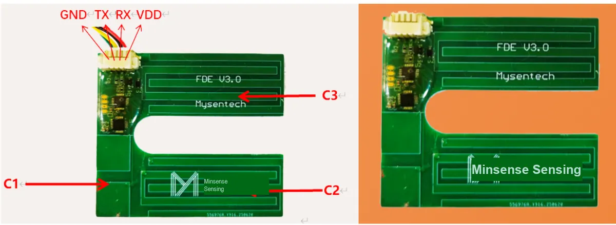
This figure illustrates the module appearance and installation configuration of the FDE Sensor, which facilitates the understanding of its application location.
2. Introduction to Main Chips
2.1 Chip Overview
Minyuan High-Precision Differential Capacitive Sensing Chip MDC04 determines the change in frosting thickness based on variations in dielectric constant, where the frosting thickness is directly proportional to the capacitance value.
2.2 Pin Definition
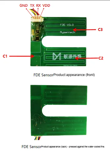
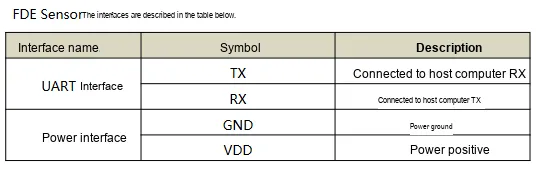
This diagram illustrates the pin definition of the FDE module, which is used to complete the UART interface connection.
2.4 Performance Parameters
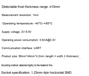
This figure presents the performance parameters of the FDE module, which can be used for the evaluation of power supply and measurement capabilities.
2.5 Communication Interfaces and Related Protocols
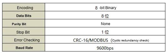
This diagram illustrates the basic communication parameters and protocol formats, which serve as the foundation for implementing host communication.
This diagram supplements the communication reading example to help understand the query method for temperature and capacitance data.
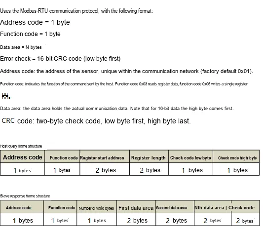
This diagram presents additional communication examples, which can be used as a reference for debugging the frames sent and the response frames returned by the host.
2.6 Register Definition
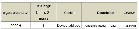
This figure lists the main register addresses and field meanings of the FDE module.
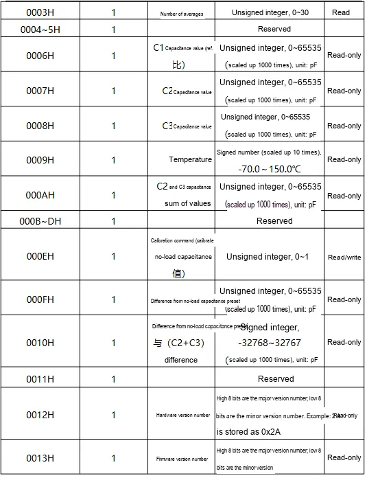
This diagram supplements the subsequent register definitions, which can be used for function configuration and data reading development.
III. Circuit Engineering
3.1 Circuit Source Engineering
To obtain the source project of the circuit, please refer to the link below:
https://mysentech.com/productinfo/118983.html
3.2 Module Usage Instructions
3.2.1 Module Test Environment Setup and Notes
When using this module, please note that the sensor should be attached to the refrigerator fin with 3M double-sided adhesive tape on its backside and fit tightly against the fin:
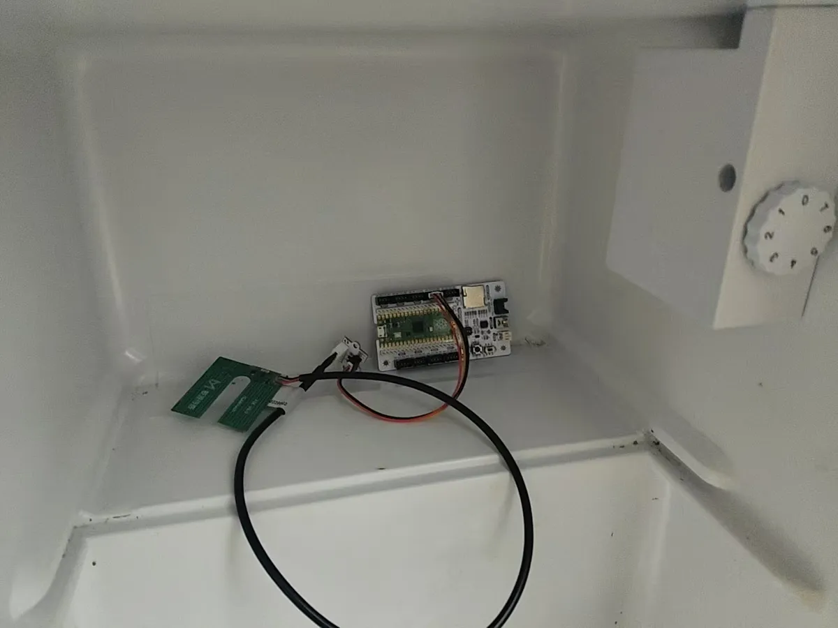
We can use ice blocks or ice surfaces of different thicknesses to fit the sensing area of the sensor (simulating frost formation on refrigerator fins), observe whether the value changes linearly with the frost thickness ranging from 0 to 10 mm, and verify the detection accuracy.
3.2.2 Usage of Modbus Poll
Modbus Poll is a universal Modbus master debugging tool compatible with all capacitive sensors in this series that support the Modbus-RTU protocol. It enables quick serial communication debugging, real-time data reading and log export between sensors and computers, serving as a universal host computer tool for verifying sensor functions and collecting test data. The software supports Modbus RTU/ASCII/TCP/IP protocols, is compatible with multiple register types and data formats, and its operation process is universal for the entire series of sensors.
Before use, you need to complete the software installation and activation first. You can download the installation package through official channels; the first launch supports a 30-day trial, and you can also enter a registration code for permanent activation. After the hardware connects the sensor to the computer, open the software and click "Connection" - "Connect", then configure the serial port parameters (Port Number, baud rate, data bit/parity bit/stop bit; this series of sensors defaults to the 9600 Baud, 8N1 format, subject to the specification sheet of the corresponding specific model) in the pop-up window, and confirm to establish a communication connection.
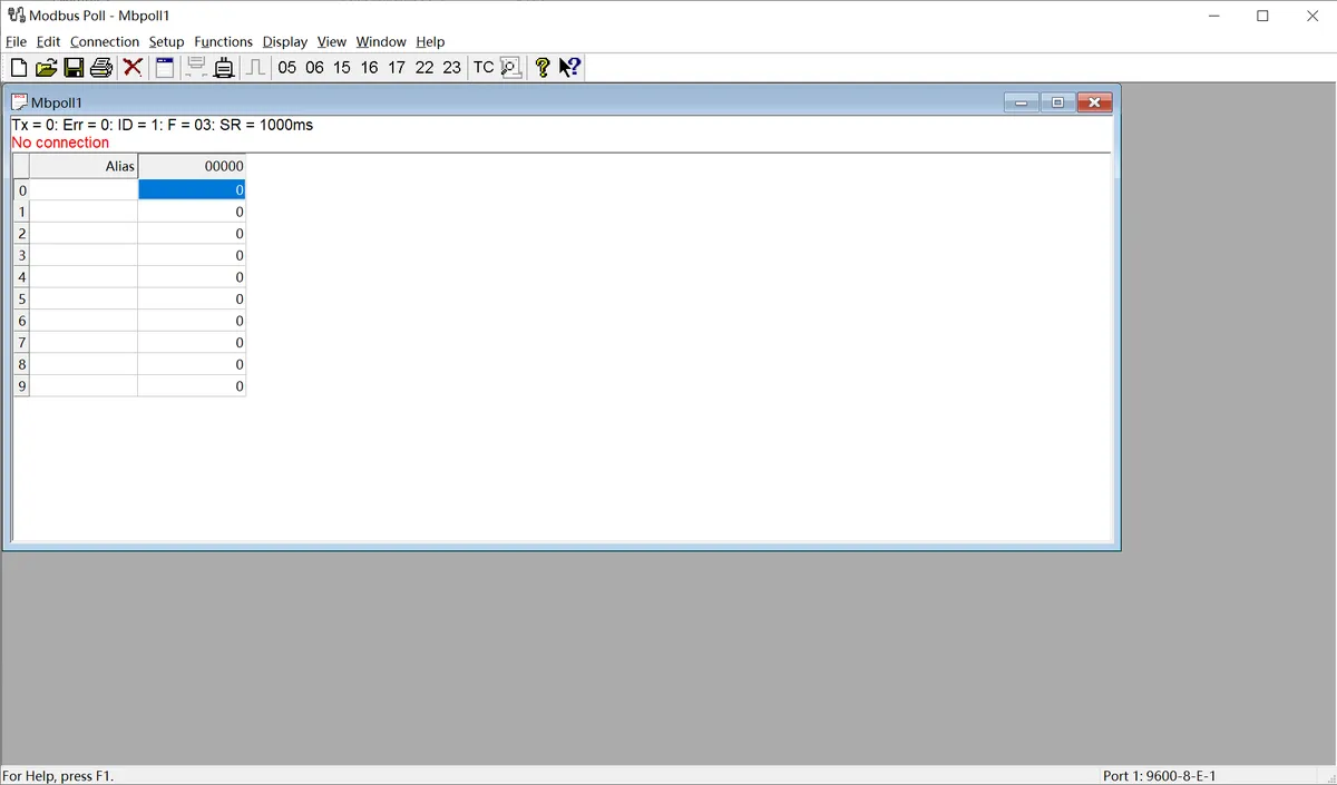
The following is a description of the general operation process:
- Serial Port Connection Configuration: After connecting the sensor to the computer via a USB-to-serial port module, launch the Modbus Poll software, click "Connection" - "Connect" on the menu bar, select the COM Port Number corresponding to the sensor in the pop-up window, and configure the serial port parameters matching the sensor (baud rate, data bits, parity check mode, stop bits; this series of sensors defaults to 9600 Baud, 8N1 format), then confirm to establish a communication connection.
- Import Sensor Configuration File: The software supports importing
. mbppre-configuration files corresponding to various sensor models. These files come with preset register addresses, data formats, and alias definitions, eliminating the need for manual register configuration. Simply open the. mbpfile for the corresponding sensor in the software to automatically load all parameters. Once the connection is established, real-time detection data of the sensor (such as dust/rain/frost thickness values, status flag bits, etc.) will be displayed directly. - Data Logging (Optional): If you need to save test data, you can configure logging rules via the "Setup" - "Excel Log" function. It supports logging data at fixed intervals or with every data update, and allows you to set a maximum number of log entries, facilitating subsequent analysis and verification of sensor data.
The above are the general basic operations of the host computer. For the. mbp preconfiguration files, specific register definitions and special configuration details of different sensor models, please refer to the content in "VII. Related Materials".
3.3 Application Experiment
Here, we use the GraftPort-RP2040 development board for testing, and the FDE Sensor frost icing sensor uses the UART interface to communicate with the main controller.
Here, we first use the HY2.0-4P cable to connect the module via the XH2.54-4P to HY2.0-4P interface module to the GraftPort-RP2040 development board's UART0 interface:
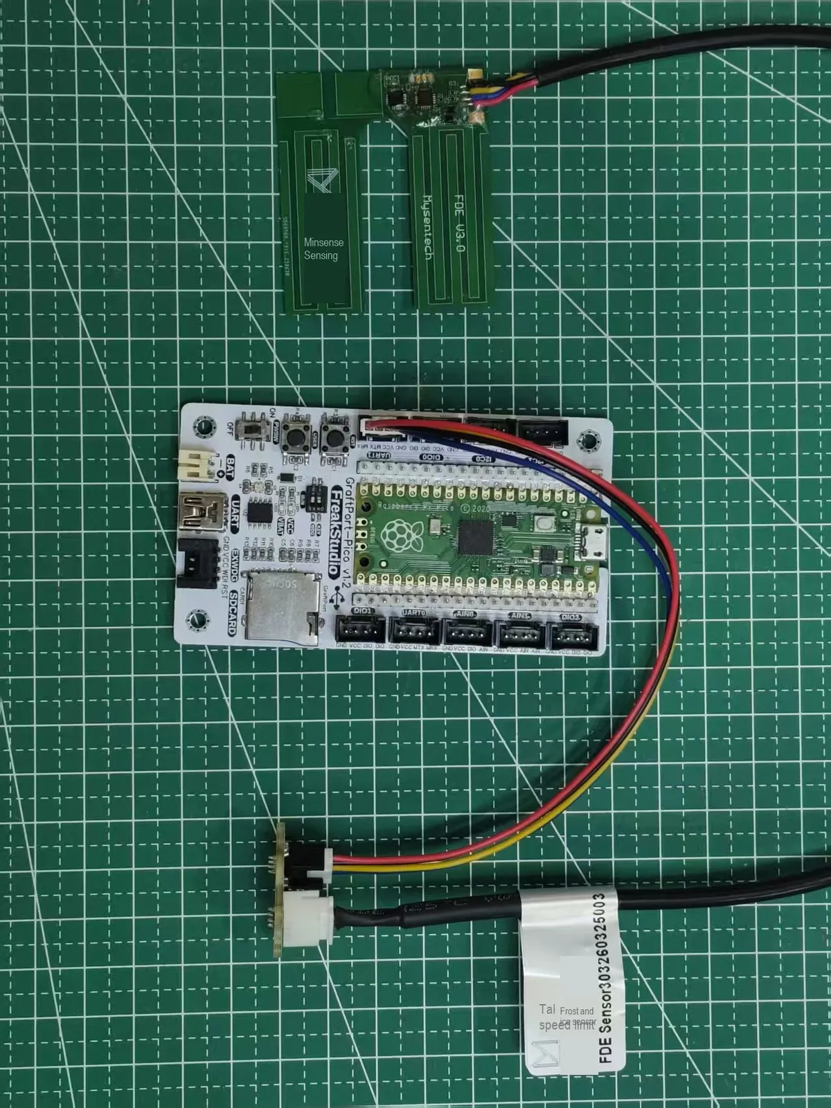
This diagram shows the connection schematic between the FDE Sensor and GraftPort-RP2040 development board.
The module connections are shown in the following table:
Development Board Pins | Module Pins | Description |
Pin 16 |
|
|
Pin 17 |
|
|
Here, we need to search for the relevant driver packages on uPyPI: https://upypi.net/zh/
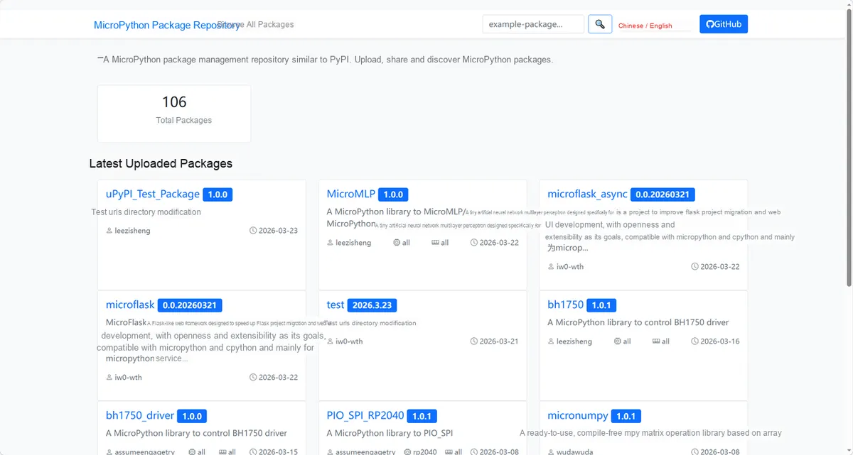
This diagram demonstrates the process of locating the FDE module driver package in uPyPI.
Enter fde_frost_driver to search, and the following will be displayed:
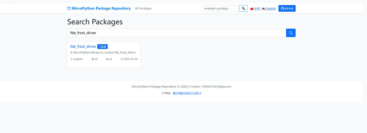
This figure shows the search results for fde_frost_driver to facilitate the confirmation of driver package information.
Click to copy the local installation command:
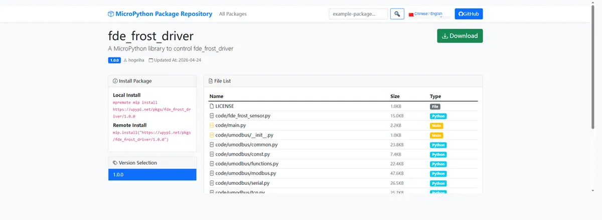
This image shows the copy interface for driver installation commands, which facilitates direct import into the driver library.
Import the module driver library code via the mip tool. Below are the usage commands for the mpremote tool:
mpremote mip install https://upypi.net/pkgs/fde_frost_driver/1.0.0Import the FDE Sensor Frost Freezing Sensor - MicroPython driver code, then copy the following main.py code into our project:
# Python env   : MicroPython v1.23.0
# -*- coding: utf-8 -*-
# @Time    : 2026/4/7 5:30 PM
# @Author  : hogeiha
# @File    : main.py
# @Description : FDE frost/ice sensor data reading and printing

# ======================================== Import Modules =========================================

# Import the time module, used for delays
import time

# Import the FDE sensor driver class
from fde_frost_sensor import FDEFrostSensor

# ======================================== Global Variables ============================================

# ======================================== Functions ============================================

# ======================================== Custom Classes ============================================

# ======================================== Initialization configuration ===========================================

# Wait 3 seconds to ensure the system is stable
time.sleep(3)
# Print the startup banner
print("FreakStudio: FDE Sensor Data Reading")
# Create the FDE sensor object, parameters: slave address 1, UART number 0, TX pin 16, RX pin 17
sensor = FDEFrostSensor(slave_addr=1, uart_id=0, tx_pin=16, rx_pin=17)

# ========================================  Main Program  ============================================

# Calibration value: calibrate the no-load capacitance value (currently commented out, can be uncommented when needed)
# sensor.fde_set_calibration(1)

# Print the data header
print("=== FDE Sensor Real-time Data ===")

# Get and print the temperature value (scaled by 10, unit: °C)
print(f"Temperature: {sensor.fde_temperature():.1f} °C")
# Get and print the C1 capacitance value (unit: pF)
print(f"C1 Capacitance: {sensor.fde_c1():.3f} pF")
# Get and print the C2 capacitance value (unit: pF)
print(f"C2 Capacitance: {sensor.fde_c2():.3f} pF")
# Get and print the C3 capacitance value (unit: pF)
print(f"C3 Capacitance: {sensor.fde_c3():.3f} pF")
# Get and print the sum of the C2 and C3 capacitance (unit: pF)
print(f"C2+C3 Sum: {sensor.fde_c2_c3_sum():.3f} pF")
# Get and print the no-load capacitance preset value (unit: pF)
print(f"No-load Capacitance Preset: {sensor.fde_no_load_cap()}")
# Get and print the hardware version number
print(f"Hardware Version: {sensor.fde_hw_ver()}")
# Get and print the firmware version number
print(f"Firmware Version: {sensor.fde_fw_ver()}")
# Print the ending separator line
print("============================")
Burn the code, open the terminal, and the output is as follows:
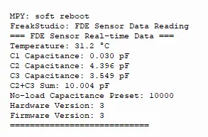
This diagram shows the output result of the FDE sample program, which can verify the temperature and multi-channel capacitance reading functions.
4. Drivers
fde_frost_driver.zip 45 KB
5. BOM & Recommended Alternative Parts
None.
VI. Revision History
Document Version | Date of Modification | Modifier | Revised Content |
v1.0 | 2026-04-24 | Hou Junhan | Initialize Document |
v1.1 | 2026-05-20 | Li Zisheng | Add introduction and the usage of 3.2.2 Modbus Poll |
VII. Relevant Materials
FDE+Sensor_Frost_and_Ice_Sensor_Product_Brief-Minyuan_202512-2.pdf 733 KB