Contents
- I. Module Introduction
- II. Introduction to Major Chips
- 2.1 Chip Overview
- 2.2 Pin Definition
- 2.3 Functional Block Diagram
- 2.4 Performance Parameters
- 2.5 Reference Circuit
- 2.6 Chip Configuration
- 2.7 Communication Interfaces and Related Protocols
- 2.8 PCB Routing Notes
- III. Instructions for Circuit Engineering and Module Usage
- 3.1 Circuit Source Engineering
- 3.2 Module Usage Instructions
- 3.3 Application Experiment
- IV. Drivers
- 5. BOM & Recommended Alternative Parts
- VI. Revision History
- VII. Relevant Materials
- 7.1 Chip Datasheet
- 7.2 Unique Icons for PCB Silk Screen
I. Module Introduction
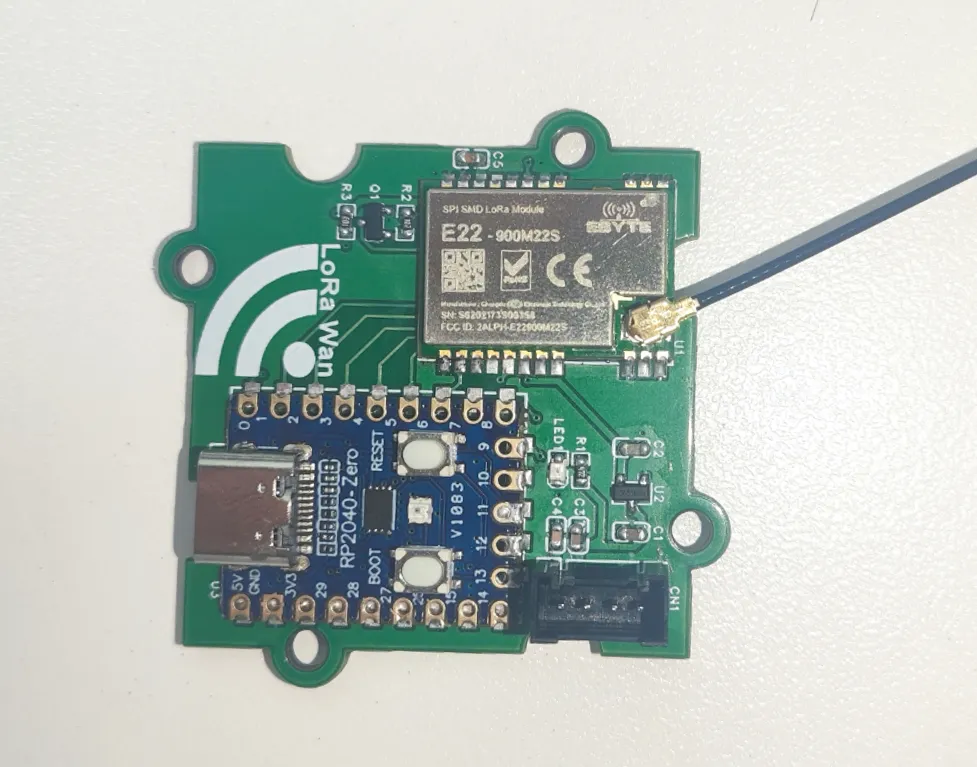
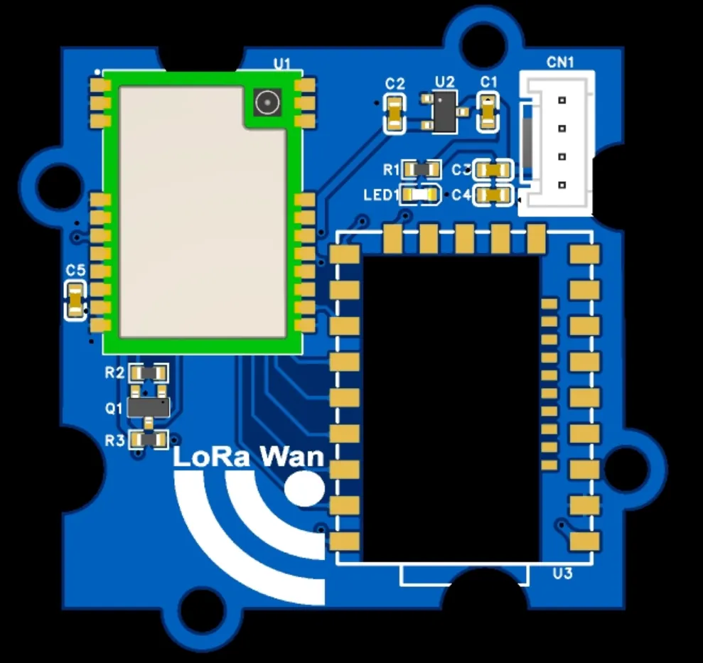
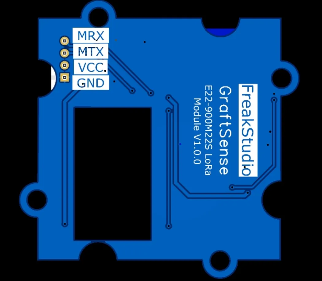
The LoRa communication module based on E22-900M22S implements long-distance wireless communication functions via the E22-900M22S RF module. Its internal core is the Semtech SX1262, and externally, the RP2040-Zero completes register configuration and data transmission/reception through the SPI interface. This board is equipped with a 5V-to-3.3V power supply circuit, a DIO2 automatic RF switch control circuit, and a 4-pin external interface, making it suitable for sensor nodes, industrial telemetry, environmental monitoring, and other medium-to-long-distance low-speed wireless communication scenarios.
The E22-900M22S is a pure RF transceiver module that does not come with a serial port transparent transmission firmware. The external main controller is required to be responsible for LoRa parameter configuration, data encapsulation, transmission, reception and error recovery; the RP2040-Zero on this board takes on this control role.
II. Introduction to Major Chips
This module is designed with the E22-900M22S RF module. The module takes the SX1262 as its core, and integrates RF matching, a 32MHz active temperature-compensated crystal oscillator, and IPEX/stamp hole antenna interfaces; the RP2040-Zero serves as the external controller, and interacts with the module via SPI, BUSY, NRST and DIO1 pins.
2.1 Chip Overview
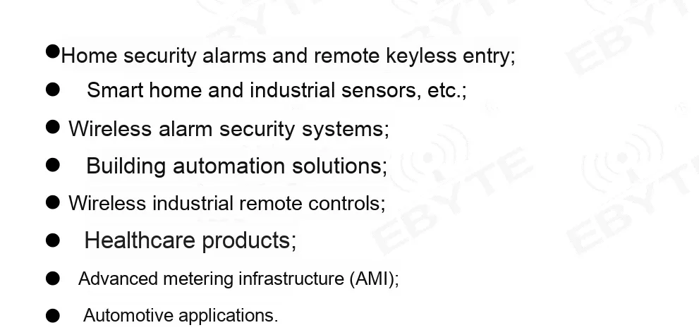
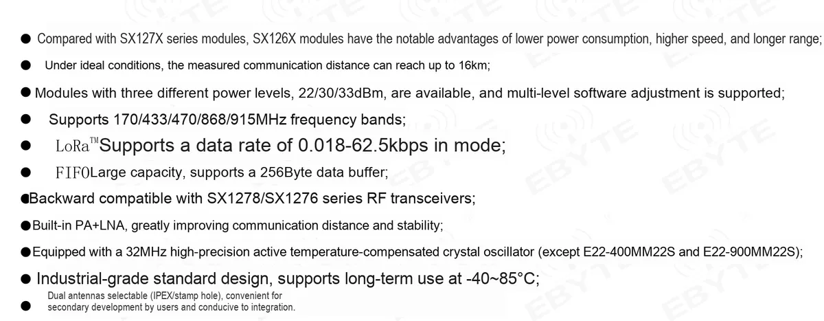
The E22-900M22S is an 850-930MHz LoRa SMD module developed by Ebyte based on the SX1262. Compared with the previous generation SX127x series, the SX1262 has been further optimized in terms of power consumption, communication speed and receiving performance; LoRa modulation can still maintain strong anti-interference capability under low signal-to-noise ratio conditions, making it suitable for applications featuring small data volume, long distance and low duty cycle.
2.2 Pin Definition
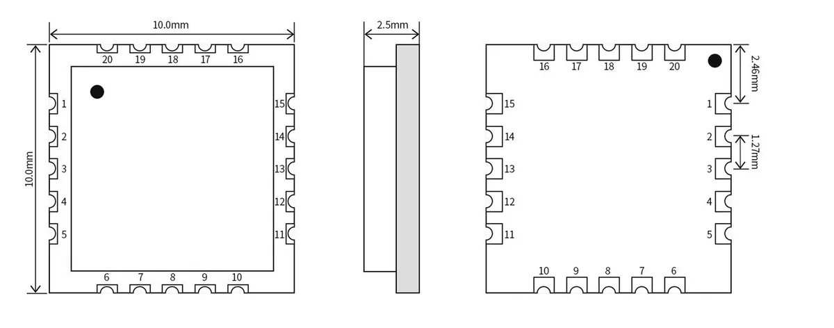
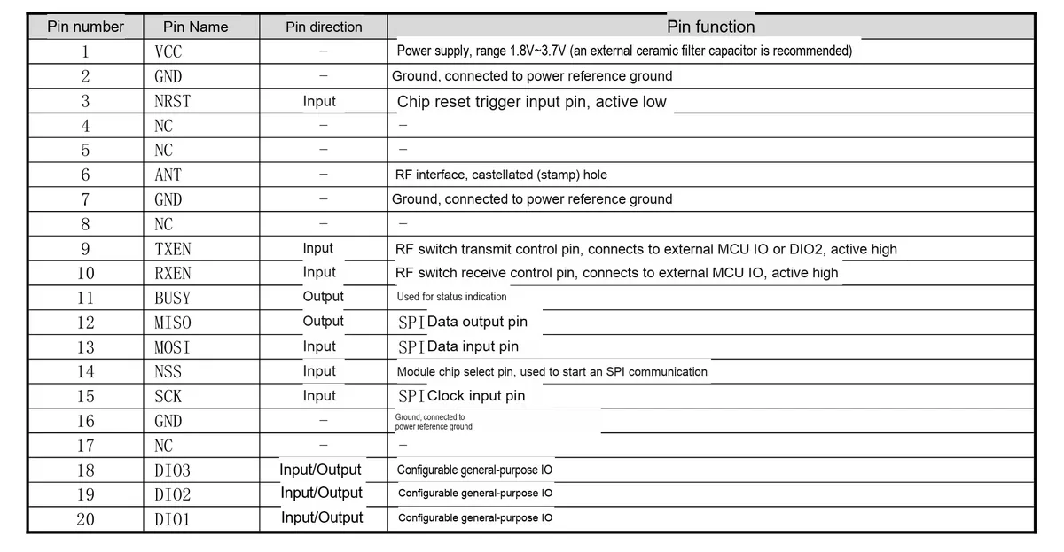
The E22-900M22S features 22 stamp hole pins. Multiple GND pins shall be connected to the ground plane of the motherboard with low resistance; the definitions of VCC, SPI, control signals and antenna interface are as follows.
2.3 Functional Block Diagram
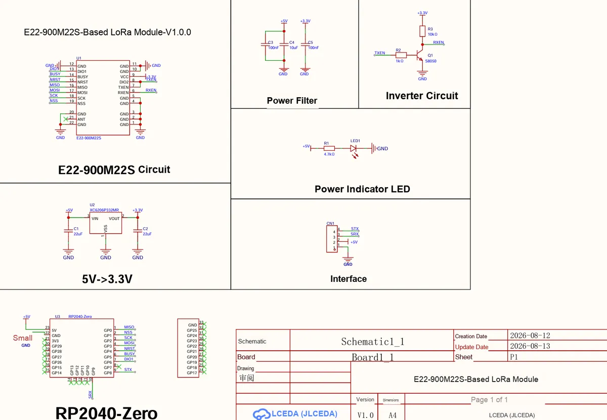
The functional link of this module can be interpreted as "external interface → RP2040 main controller → SPI/control signal → E22-900M22S → antenna". The RP2040 is responsible for protocol and application logic, the E22 module undertakes LoRa/FSK baseband processing and radio frequency transceiver, and the DIO2/TXEN/RXEN network handles the interlocking of transmit and receive channels.
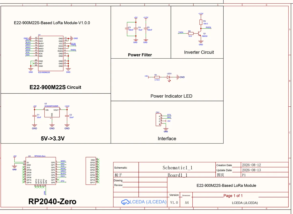
Figure 5 Actual Schematic Diagram Corresponding to the Functional Block Diagram of This Board
functional unit | Main Devices/Signals | Functions |
main controller | RP2040-Zero | Run MicroPython drivers, application protocols, and serial port interactions |
Wireless Transceiver | E22-900M22S / SX1262 | LoRa/FSK modulation, FIFO, frequency and power control |
Digital Interface | MISO/MOSI/SCK/NSS | SPI data channel between the main controller and the module |
Status Control | BUSY/NRST/DIO1 | Busy state, hard reset, and transmit-receive event interrupts |
RF switch | DIO2/TXEN/Q1/RXEN | Automatic TX/RX channel switching |
Power Supply | XC6206P332MR | Convert 5V to 3.3V to power the module |
2.4 Performance Parameters
The table below lists the main performance parameters of the E22-900M22S in its official manual. The test results will vary depending on the power supply, antenna, frequency point, environment and wireless parameters.
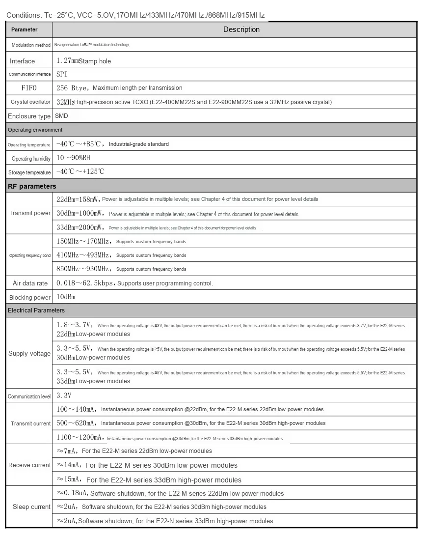
Parameters | Typical / Range | Description |
core chip | SX1262 | LoRa/FSK RF Transceiver |
Operating Frequency Band | 850-930MHz | Support frequency band customization |
Transmit Power | Max. approx. 22dBm | Approximately 158 mW, multi-stage adjustable |
Supply Voltage | 1.8-3.7V | It meets the rated output requirement when the operating voltage is ≥3V |
emission current | Approx. 100-140mA | 22dBm Instantaneous Current |
Receive current | Approx. 7mA | Official Typical Value |
quiescent current | Approximately 0.18 uA | Software shutdown conditions |
Air Rate | 0.018-62.5kbps | LoRa Mode |
Reference Distance | Approximately 6 km | Clear and open environment, 2.4 kbps, antenna height of 2 m |
Operating Temperature | -40℃ to + 85℃ | Industrial Grade Range |
2.5 Reference Circuit
2.5.1 E22-900M22S Module Section (U1)
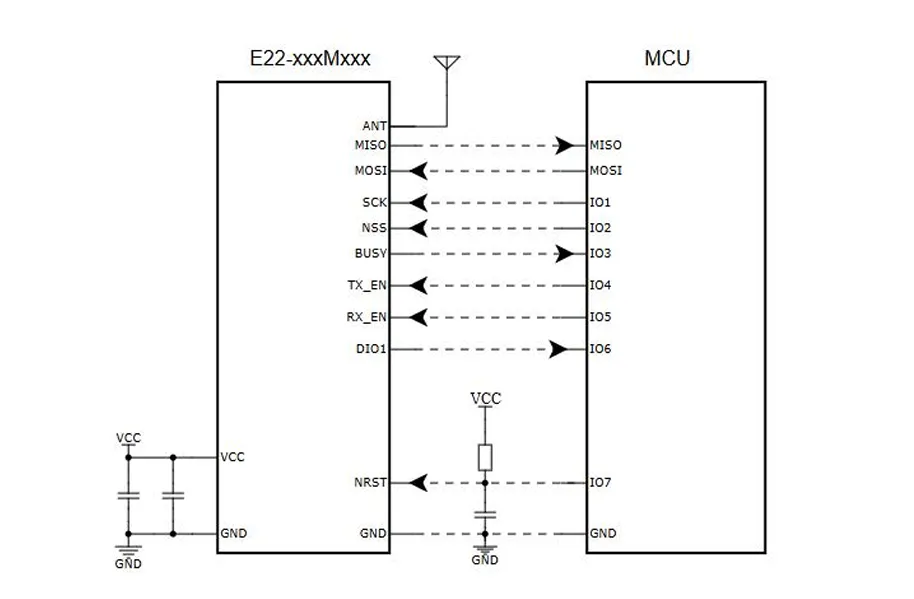
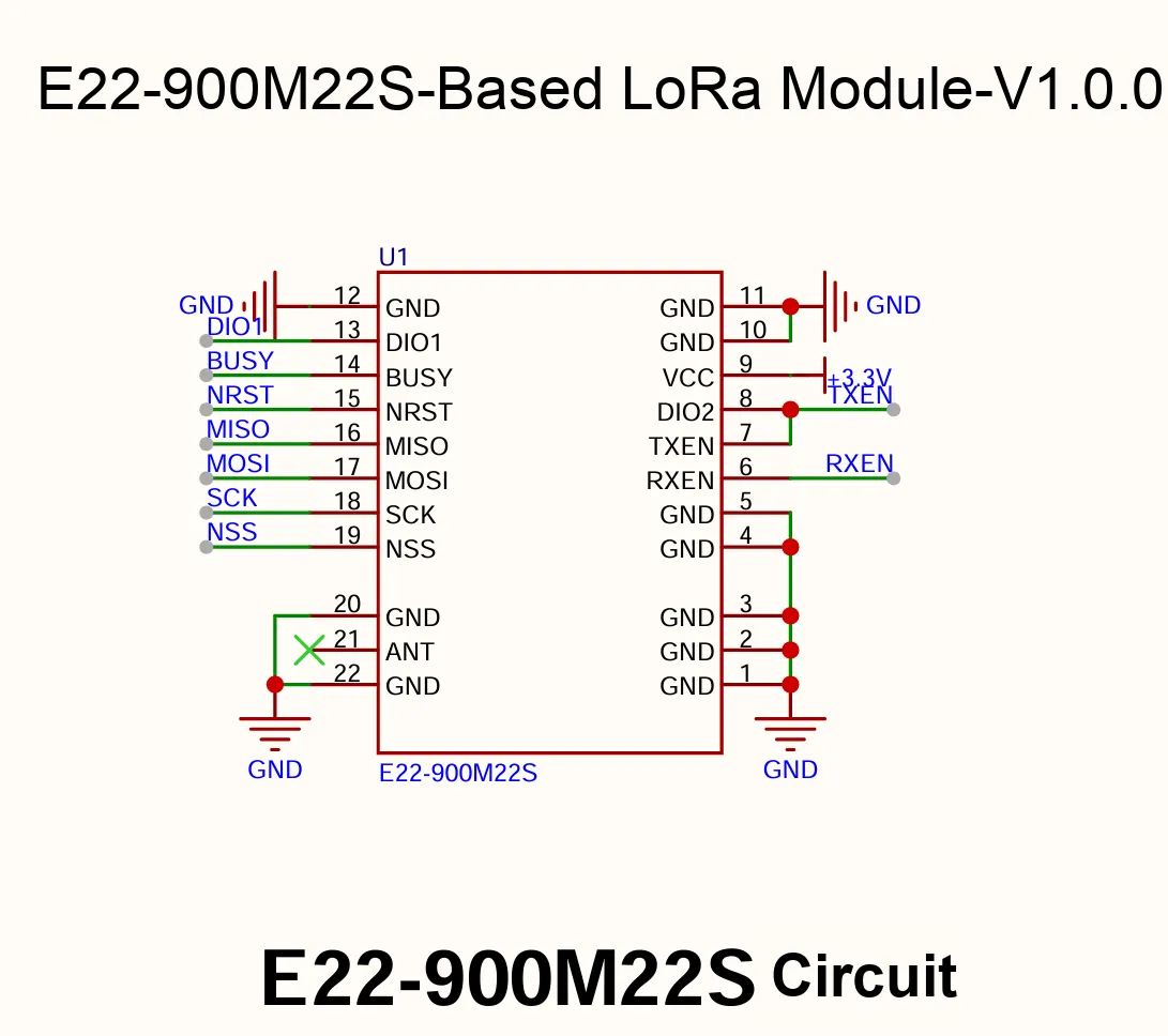
U1 is the core radio frequency module. VCC is connected to + 3.3V, MISO, MOSI, SCK and NSS are connected to RP2040 SPI0, and NRST, BUSY and DIO1 are respectively used for reset, busy status and interrupt. The IPEX interface of the module is connected to an 850-930MHz matched antenna.
2.5.2 5V to 3.3V Power Conversion Section
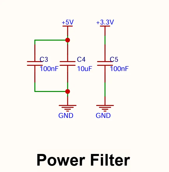
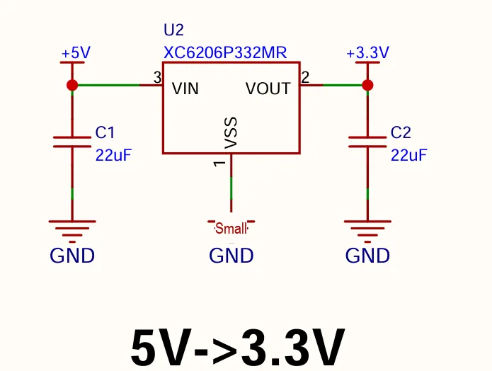
U2 adopts the XC6206P332MR to convert the + 5V input from CN1 to + 3.3V. C1 and C2 are 22uF input/output energy storage capacitors; C3 and C5 are 100nF high-frequency decoupling capacitors, and C4 is a 10uF filter capacitor. When the module is transmitting at maximum power, the 3.3V voltage drop, ripple and LDO temperature rise shall be measured practically.
2.5.3 DIO2 RF Switch and Inverter Circuit
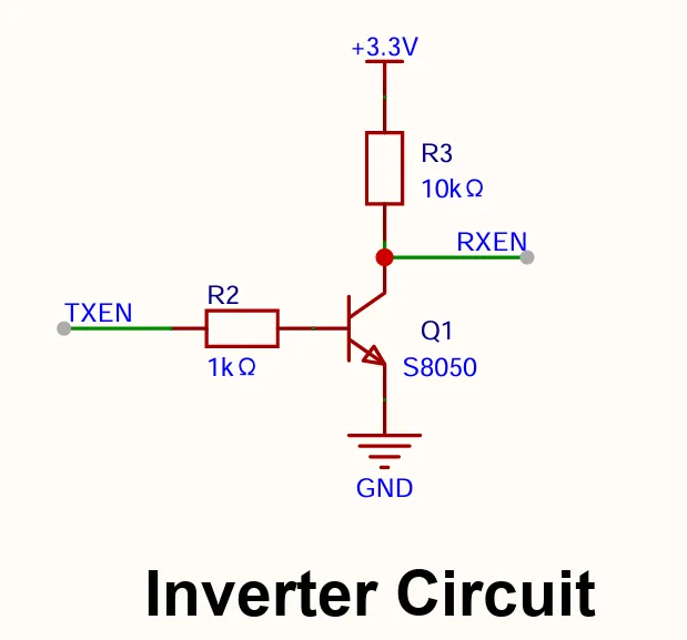
DIO2 is directly connected to TXEN. After the software executes SetDIO2AsRfSwitchCtrl (0x9D + 0x01), DIO2/TXEN will be automatically pulled high during transmission; Q1 (S8050), R2 (1kΩ) and R3 (10kΩ) invert TXEN to generate RXEN, thereby realizing the interlock between the transmit and receive channels.
2.5.4 RP2040-Zero Main Control Unit (U3)
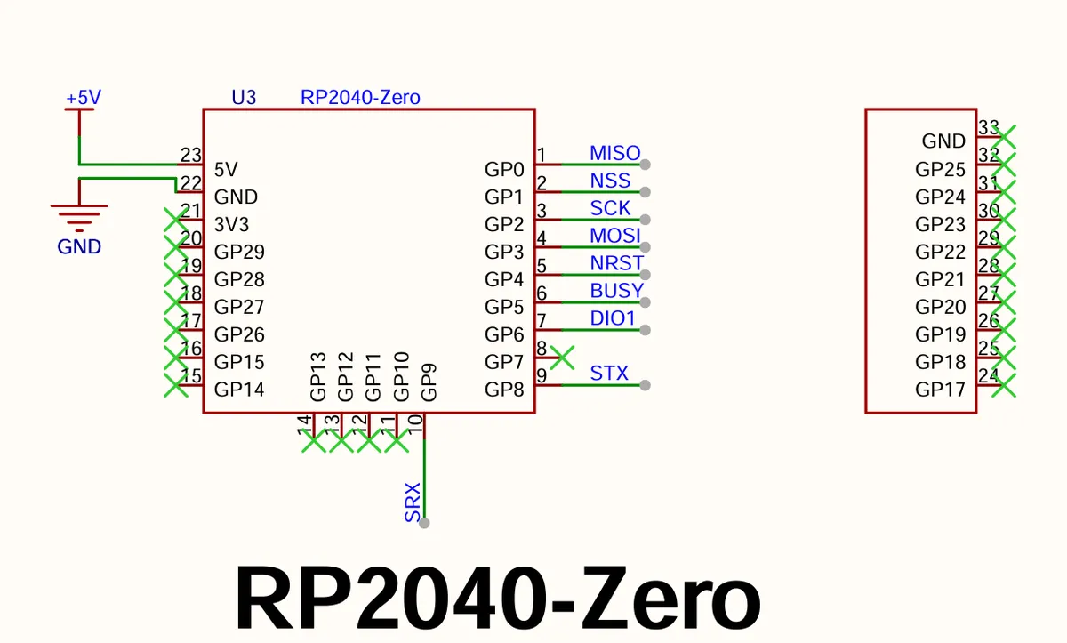
RP2040-Zero drives the SX1262. GP0/GP1/GP2/GP3 correspond to MISO/NSS/SCK/MOSI, and GP4/GP5/GP6 correspond to NRST/BUSY/DIO1; GP8/GP9 serve as the STX/SRX of UART1 and are routed to CN1.
2.5.5 Power Indicator Section
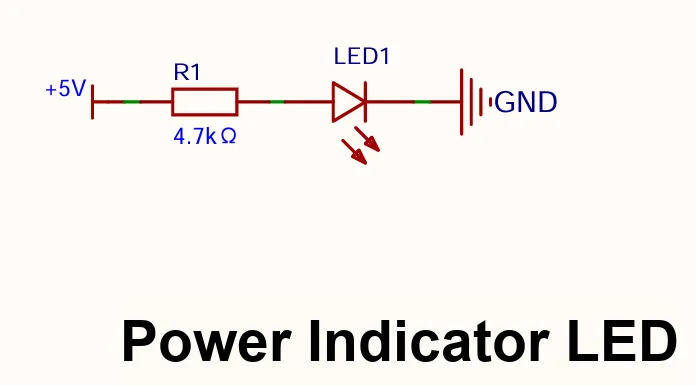
LED1 is connected in series with R1 (4.7kΩ) between + 5V and GND to indicate that the external power supply has been connected. This indicator does not imply that the 3.3V supply is stable, nor can it replace the power-on voltage check.
2.5.6 External Interface Section (CN1)
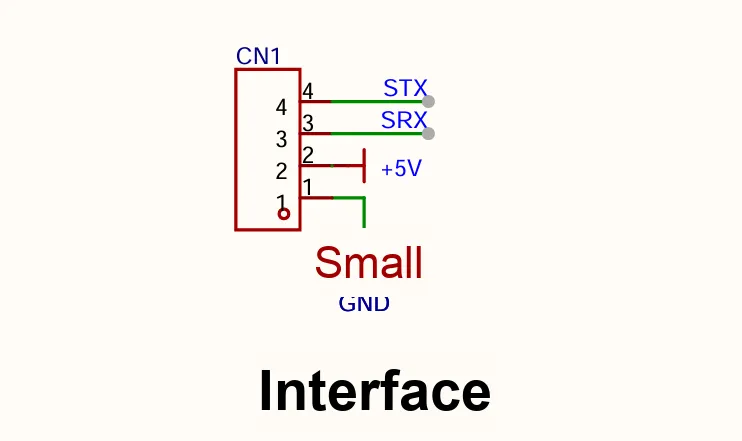
CN1 provides GND, + 5V, SRX and STX. SRX and STX are the receive and transmit signals of RP2040 UART1, not the UART of the E22 module; external devices should connect their TX to SRX, RX to STX, and share a common ground with this board.
2.6 Chip Configuration
This module is not a Plug and Play serial port transparent transmission module, and the SX1262 configuration must be completed by the RP2040 via SPI. During initialization, it is necessary to sequentially process reset, BUSY waiting, TCXO, modulation parameters, frequency, power, DIO2 RF switch and DIO1 interrupt.
Configuration Item | Recommended starting value for this board | Description |
Frequency | 915.0 MHz (example) | Adjustment must be made in accordance with local regulations and antenna frequency bands. |
Bandwidth BW | 125kHz | Smaller bandwidth usually corresponds to higher sensitivity and lower rate |
Spreading Factor SF | SF9 | Both ends must be consistent |
Coding Rate (CR) | 4/7 (Drive Parameter 7) | Both ends must be consistent |
synchronization word | 0x12 | Common values for Virtual Private Cloud |
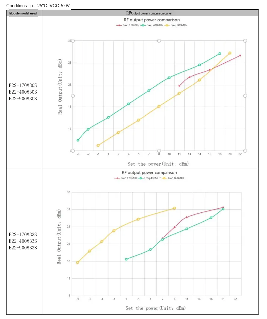
Output Power | Pre 10-14dBm | Increase the power supply and antenna performance step by step after verification |
TCXO Voltage | 2.2V | E22-M Official Manual Requirements |
DIO2 RF switch | Enable | Required for automatic TXEN/RXEN switching of this board |
2.7 Communication Interfaces and Related Protocols
2.7.1 Brief Introduction to SPI Communication Principles
As an SPI master, the RP2040 selects the E22 module via NSS, and uses SCK, MOSI and MISO to transmit commands, parameters, statuses and FIFO data. Before transmission, it is required to wait for the BUSY signal to be released; after transmission or reception is completed, DIO1 generates an interrupt, and the driver reads the IRQ status and clears the flag.
RP2040 | E22 Network | Direction (main control perspective) | Function |
GP0 | MISO | Input | Read status and FIFO data |
GP1 | NSS | Output | SPI Chip Select, Active Low |
GP2 | SCK | Output | SPI Clock |
GP3 | MOSI | Output | Write commands, parameters and data |
GP4 | NRST | Output | Module hardware reset |
GP5 | BUSY | Input | Command execution busy status |
GP6 | DIO1 | Input | Interrupts such as transmission and reception completion |
2.7.2 LoRa Transceiver and Driver Interface
docs/Github_Reference/micropySX126X-master provides the MicroPython driver for the SX1262. The driver's begin () method configures LoRa parameters, TCXO, output power and DIO2 RF switch; the send () and recv () methods are used for transmitting and receiving byte data respectively.
from sx1262 import SX1262
sx = SX1262(spi_bus=0, clk=2, mosi=3, miso=0,
            cs=1, irq=6, rst=4, gpio=5)

state = sx.begin(freq=915.0, bw=125.0, sf=9, cr=7,
                 syncWord=0x12, power=14, currentLimit=140.0,
                 preambleLength=8, implicit=False, crcOn=True,
                 tcxoVoltage=2.2, useRegulatorLDO=False,
                 blocking=True)
print(SX1262.STATUS[state])
Note: The frequency and power values in this example are for software structure illustration only. For official products, settings must be configured in compliance with the regulations of the sales/use region, antenna gain specifications and certification requirements.
2.8 PCB Routing Notes
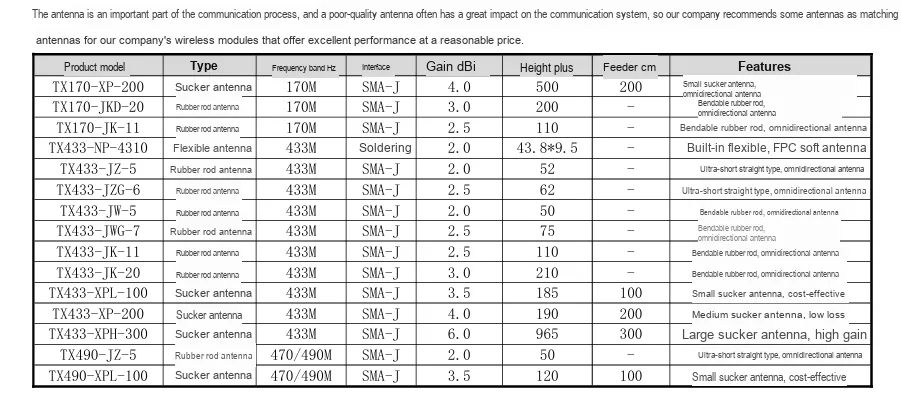
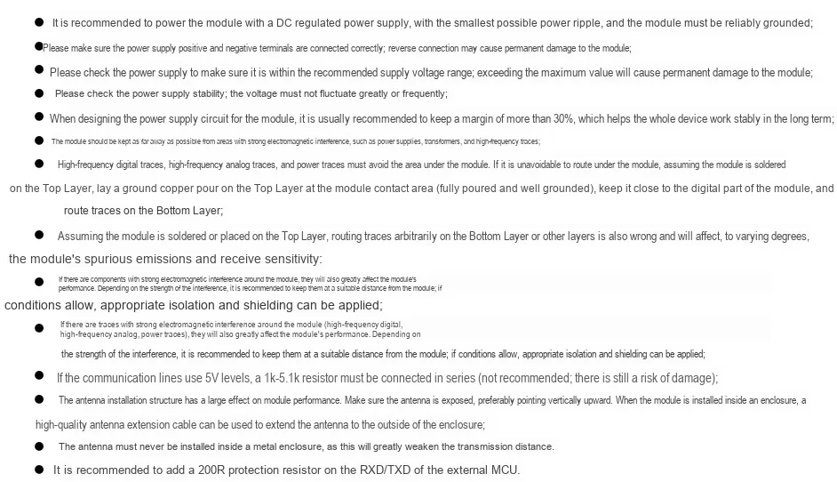
- Keep the module as far away from switching power supplies, USB high-speed cables, crystal oscillators, clocks, and high-current traces as possible.
- Maintain continuous reference below the digital area of the module, and reserve clearance for the antenna and the IPEX area in accordance with the antenna scheme.
- SPI traces should be short and routed in groups; for SCK and NSS signals, long stubs, crossing splits, and proximity to strong interference sources shall be avoided.
- Place the 100nF decoupling capacitor close to the VCC/GND of the module, and use multiple GND stamp holes for low-resistance grounding.
- Antennas shall not be placed inside metal enclosures; the feed cables shall be short, low-loss and securely fixed.
- Reserve test points for VCC, BUSY, NRST, DIO1, DIO2/TXEN, RXEN and SPI.
III. Instructions for Circuit Engineering and Module Usage
3.1 Circuit Source Engineering
To obtain the source code of the circuit, please follow the official account [Freak Embedded]
3.2 Module Usage Instructions
This module contains two main controllers for different purposes:
- On-board main controller of the module: The RP2040-Zero inside the module directly controls the E22-900M22S via the SPI interface.
- External Application Master Controller: The RP2040-Zero or RP2040 Pico of the user connection module controls the entire LoRa module via the UART interface.
The E22-900M22S internally adopts the SX1262 radio frequency chip. The SX1262 itself communicates via the SPI interface. In addition to connecting to SPI signals including MOSI, MISO, SCK and NSS, it also requires the use of control signals such as RESET, BUSY and DIO1.
If an external application directly controls the E22 as the master controller, the user needs to complete the following tasks:
- Connect the SPI and multiple control signals correctly;
- Master the SPI communication mode;
- Understand the commands and registers of the SX1262;
- Configure the frequency, spreading factor, coding rate and transmit power;
- Judge
BUSYstatus and handleDIO1interrupt; - Handle sending, receiving, timeout and exception states.
For users who are just getting started with LoRa, these low-level operations are relatively complicated, and it is also easy to cause the module to fail to work properly due to incorrect wiring or parameter configuration.
To lower the barrier to usage, this module is equipped with an onboard RP2040-Zero. The onboard RP2040-Zero is responsible for handling the SPI communication, chip initialization, parameter configuration, and wireless data transmission and reception of the E22; the external application main controller only needs to send high-level control commands to the module via UART.
The differences between the two control modes are as follows:
| Comparison item | External host controls E22 directly | Using this module |
|---|---|---|
| Communication interface | SPI and multiple control signals | UART |
| External wiring | MOSI, MISO, SCK, NSS, RESET, BUSY, DIO1, etc. | VCC, GND, RX, TX |
| Low-level driver | Written or ported by the user | Run by the module's onboard RP2040 |
| Chip initialization | Handled by the user | Done automatically by the module |
| Wireless transmit/receive | Requires calling the SX1262 low-level interface | Call the high-level UART API |
| Difficulty of use | Higher | Lower, suitable for beginners |
It should be noted that this module does not simply perform a transparent conversion of SPI bytes to UART bytes; instead, the onboard RP2040-Zero runs a complete E22 driver program.
The external application main controller sends E22UARTClient to transmit UART JSON commands including ping, initialize, send, receive and status; the E22UARTBridge on the onboard RP2040-Zero is responsible for parsing these commands and then invoking the E22 driver to complete the corresponding operations.
For example, after the external application master control sends the send command, the onboard RP2040-Zero will complete the following processing:
External application host calls e22.send()
            │
            ▼
E22UARTClient generates a UART JSON command
            │
            ▼
E22UARTBridge receives and parses the command
            │
            ▼
E22_900M22S driver controls the SX1262 over SPI
            │
            ▼
Send LoRa wireless data
            │
            ▼
Return the execution result to the external application host over UART
With this design, users do not need to understand the underlying registers and SPI timing of the SX1262; they only need to connect VCC, GND, RX and TX, and call the high-level APIs to implement LoRa communication.
3.2.1 Program Running Location
The project code structure is as follows:
lora_driver/
├── code/
│   ├── main.py
│   │   └── Entry program of the module's onboard host
│   ├── e22_uart_bridge.py
│   │   └── UART command parsing and forwarding program of the module's onboard host
│   ├── e22_900m22s.py
│   │   └── E22-900M22S board-level adaptation driver
│   ├── sx1262.py
│   │   └── SX1262 initialization, power, and transmit/receive control
│   ├── sx126x.py
│   │   └── SX126X SPI communication and transmit/receive state machine
│   ├── _sx126x.py
│   │   └── SX126X command, register, and parameter constants
│   ├── e22_uart_client.py
│   │   └── High-level UART API used by the external application host
│   └── e22_uart_protocol.py
│       └── UART protocol shared by the onboard host and the external host
│
└── examples/
    ├── pico_uart_example.py
    │   └── Basic usage example for the external application host
    ├── pico_node_tx.py
    │   └── Sender node example for the external application host
    └── pico_node_rx.py
        └── Receiver node example for the external application host
3.2.2 Onboard Main Control Code of the Module
The module's onboard RP2040-Zero requires the full E22 low-level driver and UART command bridge program to run. Please download the driver Compressed Packet provided in this section, and upload the following files in the code directory inside the Compressed Packet to the root directory of the MicroPython file system on the module's onboard RP2040-Zero:
_sx126x.py
sx126x.py
sx1262.py
e22_900m22s.py
e22_uart_protocol.py
e22_uart_bridge.py
main.py
After the module is powered on again or reset, MicroPython will automatically execute main.py to start the UART command bridge service.
Document Purpose Description
| File | Running location | Main Function |
|---|---|---|
| _sx126x.py | Module onboard host controller | Defines SX126X commands, registers, IRQ, operating states and LoRa parameter constants |
| sx126x.py | Module onboard host controller | Implements SPI communication, BUSY waiting, register access, FIFO operations and the transmit/receive state machine |
| sx1262.py | Module onboard host controller | Implements SX1262 initialization, power configuration and data transmit/receive on top of SX126X |
| e22_900m22s.py | Module onboard host controller | Adapts frequency, power, TCXO and RF switch for the E22-900M22S |
| e22_uart_protocol.py | Shared by both host controllers | Implements encoding and decoding of UART JSON command frames and binary data conversion |
| e22_uart_bridge.py | Module onboard host controller | Parses commands sent by the external host controller and calls the E22 driver to execute operations |
| main.py | Module onboard host controller | Creates SPI, UART and GPIO objects and starts the onboard program |
Program Call Relationship
The aforementioned files do not run independently, and their call relationships are as follows:
main.py
├── Create SPI, UART and GPIO objects
├── Create the E22_900M22S object
│   └── E22_900M22S
│       └── SX1262
│           └── SX126X
│               └── _sx126x constants
│
└── Create the E22UARTBridge object
    ├── Parse UART commands using e22_uart_protocol
    └── Call E22_900M22S to perform initialization, transmission and reception
The data processing procedure is as follows:
External application host
    │ UART JSON command
    ▼
e22_uart_protocol.py
    │ Command parsing
    ▼
e22_uart_bridge.py
    │ Driver call
    ▼
e22_900m22s.py
    ▼
sx1262.py
    ▼
sx126x.py
    │ SPI
    ▼
E22-900M22S- SX126X Basic Driver Class
SX126Xis defined insx126x.py, which is responsible for the underlying SPI communication, status control, register access and FIFO operations of the SX1262.Method or property Description state Get the current SX126X operating state last_initialization_plan Get the most recent initialization step wait_while_busy() Wait for the BUSY pin to be released reset() Perform a hardware reset of the RF chip standby() Put the chip into standby state get_status() Read the current chip state set_tcxo_2_2() Configure DIO3 to output 2.2V to power the TCXO set_dio2_rf_switch() Configure DIO2 to automatically control the RF switch set_regulator_mode() Set LDO or DC-DC power supply mode set_rx_tx_fallback_standby() Set standby state to return to after TX/RX completes calibrate_all() Perform full chip calibration calibrate_image() Perform image calibration according to operating frequency clear_device_errors() Clear chip error flags get_device_errors() Read chip error flags set_packet_type_lora() Set packet type to LoRa set_lora_private_sync_word() Set LoRa private network sync word set_rf_frequency() Set RF operating frequency set_lora_modulation_params() Set bandwidth, spreading factor and coding rate set_lora_packet_params() Set preamble and payload length parameters set_sx1262_pa_config() Configure SX1262 power amplifier set_tx_params() Set TX power and ramp time read_register() Read SX1262 register write_register() Write SX1262 register apply_sx1262_pa_clamp_workaround() Apply SX1262 power amplifier clamping fix apply_lora_rx_sensitivity_workaround() Apply LoRa RX sensitivity fix configure_tx_irq() Configure TX interrupt configure_rx_irq() Configure RX interrupt set_buffer_base_address() Set TX and RX FIFO base addresses get_irq_status() Get interrupt status clear_irq_status() Clear interrupt status write_buffer() Write data to TX FIFO get_rx_buffer_status() Get RX FIFO status read_buffer() Read data from RX FIFO get_packet_status() Get RX quality information such as RSSI and SNR set_tx() Start wireless transmission set_rx() Start wireless reception wait_for_tx_done() Wait for transmission to complete wait_for_rx_done() Wait for reception to complete deinit() Clean up driver state sx126x.pyalso defines the following exception classes:Exception class Description SX126XError SX126X driver base exception SX126XTimeoutError BUSY, TX or RX timeout SX126XSPIError SPI communication exception SX126XStateError Chip state exception SX1262Chip Driver CategorySX1262is defined insx1262.pyand inherits fromSX126X.Method Description build_lora_initialization_plan() Generate LoRa initialization steps from parameters initialize_lora() Initialize SX1262 LoRa operating parameters transmit() Send one LoRa packet receive_packet() Receive data and return data, RSSI and SNR deinit() Clean up SX1262 runtime state - E22_900M22S Module Adaptation Class
E22_900M22Sis defined ine22_900m22s.py. This class adds the frequency, power, TCXO and RF switch constraints specific to the E22-900M22S based on the SX1262 driver.Method or property Description initialized Get whether the module is initialized initialization_plan Get initialization steps state Get underlying SX1262 state build_initialization_plan() Generate initialization plan according to E22 hardware constraints initialize() Configure frequency, spreading factor, coding rate and TX power send() Send 1 to 255 bytes of wireless data receive() Receive wireless data and return RSSI and SNR deinit() Exit operating state and clean up driver E22UARTBridgeCommand Bridge ClassE22UARTBridgeis defined ine22_uart_bridge.py, which is responsible for connecting the UART interface of the external application main controller and the onboard E22 driver.Method Description poll() Read and process one complete command from UART serve_forever() Continuously poll UART and process requests from the external host controller stop() Request to stop UART polling deinit() Stop service and clear protocol receive buffer _handle_frame() Decode and process one UART JSON request frame _dispatch() Call the corresponding E22 interface according to the command name _write_error() Convert exception to UART error response E22UARTBridgecurrently supports the following commands:Command Called interface Description ping None Check whether the UART command bridge is online status state, initialized Query module state initialize E22_900M22S.initialize() Initialize LoRa parameters send E22_900M22S.send() Send wireless data receive E22_900M22S.receive() Receive wireless data - UART protocol function
e22_uart_protocol.pyis responsible for encoding and decoding the UART JSON protocol.Function Description encode_frame() Encode dictionary as newline-terminated JSON command frame decode_frame() Decode UART JSON data to dictionary bytes_to_hex() Convert binary data to hexadecimal string hex_to_bytes() Restore hexadecimal string to binary data This document also defines
E22UARTProtocolError, which is used to indicate a format error in the UART command frame. - main.py entry program
main.pyserves as the boot entry for the RP2040-Zero module board. The following is the actual code fromlora_driver/code/main.py:# Python env : MicroPython v1.23.0 or later # -*- coding: utf-8 -*- # @Time : 2026/08/24 # @Author : FreakStudio # @File : main.py # @Description : RP2040-Zero E22 UART bridge composition root # @License : MIT """Create board resources, inject them, and serve the external Pico UART.""" import time from machine import Pin, SPI, UART from e22_900m22s import E22_900M22S from e22_uart_bridge import E22UARTBridge SPI_BUS = 0 SPI_BAUDRATE = 2_000_000 PIN_MISO = 0 PIN_CS = 1 PIN_SCK = 2 PIN_MOSI = 3 PIN_RESET = 4 PIN_BUSY = 5 PIN_DIO1 = 6 UART_BUS = 1 UART_BAUDRATE = 115200 PIN_UART_TX = 8 PIN_UART_RX = 9 time.sleep(3) print("FreakStudio: E22-900M22S UART bridge starting") spi = SPI( SPI_BUS, baudrate=SPI_BAUDRATE, polarity=0, phase=0, bits=8, sck=Pin(PIN_SCK), mosi=Pin(PIN_MOSI), miso=Pin(PIN_MISO), ) radio = E22_900M22S( spi=spi, cs=Pin(PIN_CS, Pin.OUT, value=1), reset=Pin(PIN_RESET, Pin.OUT, value=1), busy=Pin(PIN_BUSY, Pin.IN), dio1=Pin(PIN_DIO1, Pin.IN), busy_timeout_ms=5000, ) uart = UART( UART_BUS, baudrate=UART_BAUDRATE, bits=8, parity=None, stop=1, tx=Pin(PIN_UART_TX), rx=Pin(PIN_UART_RX), timeout=0, ) bridge = E22UARTBridge(uart, radio) print("E22_UART_BRIDGE_READY") print("UART1 TX=GP8 RX=GP9 BAUD=115200") try: bridge.serve_forever() except KeyboardInterrupt: print("Program interrupted by user") except OSError as error: print("Hardware communication error: %s" % str(error)) except Exception as error: print("Unknown error: %s" % str(error)) finally: print("Cleaning up resources...") bridge.deinit() radio.deinit() if hasattr(uart, "deinit"): uart.deinit() if hasattr(spi, "deinit"): spi.deinit() print("Program exited")The execution process of this program is as follows:
Create the SPI0 interface
    ▼
Create the E22_900M22S object
    ▼
Create the UART1 interface
    ▼
Create the E22UARTBridge object
    ▼
Execute bridge.serve_forever()
    ▼
Continuously receive and process commands from the external application host
Among them, SPI0 uses GP0 to GP6 to connect with E22; UART1 uses GP8 and GP9 to communicate with the external application main controller, with the serial port parameters configured as 115200 baud rate, 8 data bits, no parity bit and 1 stop bit.
After making such modifications, there will still be only one tertiary heading "3.2.2 On-board Main Control Code of the Module" in the article table of contents, and the internal content will not be included in the table of contents.
3.2.3 External Application Main Control Code
The external application master control needs to upload:
e22_uart_client.py
e22_uart_protocol.py
Then select an application example according to the test purpose:
pico_uart_example.py    # Basic connection and initialization test
pico_node_tx.py         # Send 20 test packets in a row
pico_node_rx.py         # Receive and verify 20 test packets
The external main control creates a device object in the following manner:
from machine import Pin, UART
from e22_uart_client import E22UARTClient

uart = UART(
    0,
    baudrate=115200,
    bits=8,
    parity=None,
    stop=1,
    tx=Pin(0),
    rx=Pin(1),
    timeout=0,
)

e22 = E22UARTClient(uart)
After that, external applications only need to use the high-level interface:
e22.ping()
e22.initialize(915.0, output_power_dbm=0)
e22.send(b"hello")
payload, rssi_dbm, snr_db = e22.receive(timeout_ms=5000)
Description of code running locations:main.py, e22_uart_bridge.py and the underlying E22/SX1262 driver run on the RP2040-Zero onboard the module board;the examples in examples/ run on the external application main controller, which also needs to upload e22_uart_client.py and e22_uart_protocol.py.The two types of programs must not be confused, nor should the examples/ files be uploaded solely to the external main controller, otherwise they will fail to run due to missing dependent files.
3.2.4 Notes
Before use, it must be confirmed that: first power off to install the 850-930MHz matching antenna, then connect to 5V; only after measuring that the VCC of the module is stable at 3.3V can the RF program be run. It is forbidden to connect 5V directly to the E22 VCC or SPI/control signals.
3.3 Application Experiment
Here, we use the GraftPort-RP2040 development board for testing, and connect the E22-900M22S LoRa communication module from EBYTE to communicate with the main controller via the UART interface.
3.3.1 External Main Control Wiring Instructions
Since during module design, the original RX network has been marked as TX, and the original TX network has been marked as RX, there is no need to cross the UART signals when connecting the external main controller to the LoRa module:
RX to RX, TX to TX
Here, we first use the HY2.0-4P connection cable to connect the module to the GraftPort-RP2040 development board's UART0 interface:
External Main Controller Based on RP2040 Pico
| LoRa module interface | RP2040 Pico interface | Description |
|---|---|---|
| VCC | VCC | Module power supply |
| GND | GND | System common ground |
| RX | GP17 / UART0 RX | UART receive signal, connected to the same-named pin |
| TX | GP16 / UART0 TX | UART transmit signal, connected to the same-named pin |
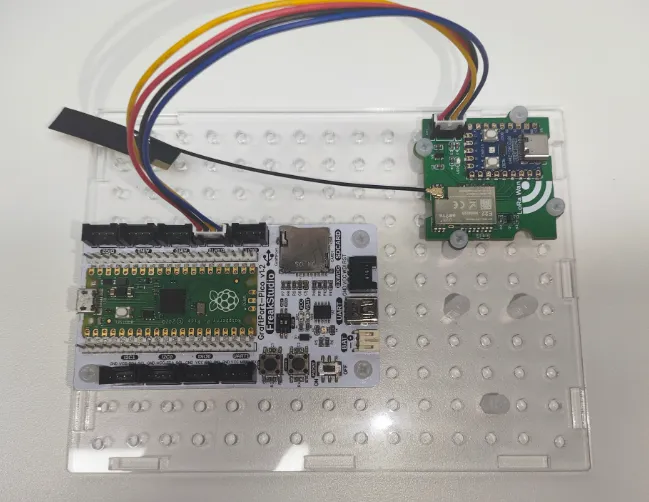
Here, two sets of modules based on the E22-900M22S are used for point-to-point communication testing: one set runs the transmitting program, while the other runs the receiving program, and the LoRa parameters at both ends must be completely identical.
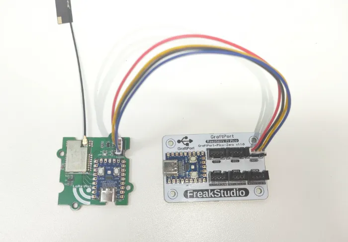
RP2040-Zero External Main Controller
| LoRa module interface | RP2040-Zero interface | Description |
|---|---|---|
| VCC | VCC | Module power supply |
| GND | GND | System common ground |
| RX | GP1 / UART0 RX | UART receive signal, connected to the same-named pin |
| TX | GP0 / UART0 TX | UART transmit signal, connected to the same-named pin |
3.3.2 Import Driver Code
- Prepare two module base plates, two matching antennas and a stable 5V power supply, and connect the antennas while the power is off.
- Copy the driver files from micropySX126X-master/lib to the /lib directory of both RP2040 boards.
- Run output/examples/e22_tx.py on the transmitter side, and run output/examples/e22_rx.py on the receiver side.
- First, conduct a short-range test at 10-14dBm to verify that the initialization status, Payload, RSSI and SNR are all normal.
- Swap the transmit/receive roles of the two boards and confirm that the hardware can communicate bidirectionally.
- After completing the power supply and antenna verification, gradually increase the power level by level and carry out tests on distance, packet loss rate and temperature rise.
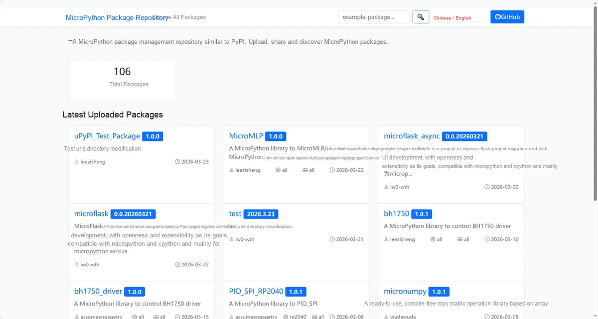
Here, we need to search for the relevant driver packages on uPyPI: https://upypi.net/zh/
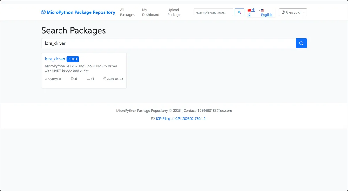
Enter lora_driver to search, and the following will be displayed:
Click to copy the local installation command:
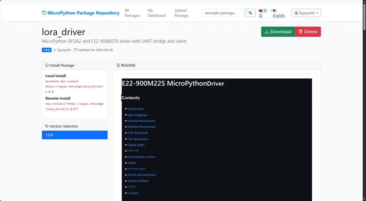
Here, we can import the module driver library code via the mip tool. The usage commands for the mpremote tool are as follows:
mpremote mip install https://upypi.net/pkgs/lora_driver/1.0.0After importing, copy the following main.py code into our project:
# Python env   : MicroPython v1.23.0 or later
# -*- coding: utf-8 -*-
# @Time    : 2026/08/20
# @Author  : E22-900M22S project contributors
# @File    : main.py
# @Description : RP2040-Zero E22 UART bridge composition root
# @License : MIT

"""Create board resources, inject them, and serve the external Pico UART."""

# ======================================== Import Modules =========================================
import time
from machine import Pin, SPI, UART

from e22_900m22s import E22_900M22S
from e22_uart_bridge import E22UARTBridge

# ======================================== Global Variables ============================================
SPI_BUS = 0
SPI_BAUDRATE = 2_000_000
PIN_MISO = 0
PIN_CS = 1
PIN_SCK = 2
PIN_MOSI = 3
PIN_RESET = 4
PIN_BUSY = 5
PIN_DIO1 = 6

UART_BUS = 1
UART_BAUDRATE = 115200
PIN_UART_TX = 8
PIN_UART_RX = 9

# ======================================== Functions ============================================
# The bridge polling loop is implemented by E22UARTBridge.

# ======================================== Custom Classes ============================================
# Hardware objects are all composed through dependency injection, so no new class is needed here.

# ======================================== Initialization ==========================================
time.sleep(3)
print("FreakStudio: E22-900M22S UART bridge starting")

spi = SPI(
    SPI_BUS,
    baudrate=SPI_BAUDRATE,
    polarity=0,
    phase=0,
    bits=8,
    sck=Pin(PIN_SCK),
    mosi=Pin(PIN_MOSI),
    miso=Pin(PIN_MISO),
)
radio = E22_900M22S(
    spi=spi,
    cs=Pin(PIN_CS, Pin.OUT, value=1),
    reset=Pin(PIN_RESET, Pin.OUT, value=1),
    busy=Pin(PIN_BUSY, Pin.IN),
    dio1=Pin(PIN_DIO1, Pin.IN),
    busy_timeout_ms=5000,
)
uart = UART(
    UART_BUS,
    baudrate=UART_BAUDRATE,
    bits=8,
    parity=None,
    stop=1,
    tx=Pin(PIN_UART_TX),
    rx=Pin(PIN_UART_RX),
    timeout=0,
)
bridge = E22UARTBridge(uart, radio)

# ========================================  Main Program  ===========================================
print("E22_UART_BRIDGE_READY")
print("UART1 TX=GP8 RX=GP9 BAUD=115200")
try:
    bridge.serve_forever()
except KeyboardInterrupt:
    print("Program interrupted by user")
except OSError as error:
    print("Hardware communication error: %s" % str(error))
except Exception as error:
    print("Unknown error: %s" % str(error))
finally:
    print("Cleaning up resources...")
    bridge.stop()
    radio.deinit()
    if hasattr(uart, "deinit"):
        uart.deinit()
    if hasattr(spi, "deinit"):
        spi.deinit()
    print("Program exited")
3.3.3 E22UARTBridge Function Description
from e22_uart_bridge import E22UARTBridgeThis statement imports the E22UARTBridge class from e22_uart_bridge.py. The import itself does not start data forwarding; you will need to create an object and start the service subsequently:
bridge = E22UARTBridge(uart, radio)
bridge.serve_forever()
Wherein:
UART: Connect to the UART interface of the external application main controller;radio: anE22_900M22Sobject controlled via SPI;E22UARTBridge: A command bridging program located between the two.
The workflow is as follows:
External application host
      │
      │ UART JSON command
      ▼
E22UARTBridge
      │
      │ Call the E22 driver interface
      ▼
E22_900M22S
      │
      │ SPI
      ▼
SX1262 LoRa chip
E22UARTBridge mainly implements the following functions:
| Function | Description |
|---|---|
| UART data reception | Continuously read data sent by the external application host controller |
| Protocol parsing | Parse newline-terminated JSON command frames |
| Command dispatch | Call the corresponding E22 driver interface according to the command |
| LoRa control | Perform initialization, wireless transmission and wireless reception |
| Result return | Return execution result, received data, RSSI and SNR via UART |
| Exception handling | Wrap parameter errors, communication errors, etc. into error responses |
The currently supported commands include:
| Command | Purpose |
|---|---|
| ping | Check UART communication between the external host controller and the module's onboard controller |
| status | Query E22 initialization state and current operating state |
| initialize | Set LoRa parameters such as frequency, spreading factor, coding rate and power |
| send | Send one wireless packet through E22 |
| receive | Receive wireless data and return data content, RSSI and SNR |
serve_forever () will continuously perform polling on the UART after startup:
while self._running:
    if not self.poll():
        time.sleep_ms(2)
Whenever a complete command is received, E22UARTBridge will parse the command, invoke E22_900M22S to perform the corresponding operation, and then return the result to the external application main controller.
Therefore,
E22UARTBridgeis not a simple transparent serial repeater, but rather a "UART command parser and E22 driver scheduler" running on the module's onboard RP2040-Zero. The external application main controller indirectly controls the E22 chip via it.
3.3.4 Communication Demonstration Description
Flash the code, open the terminal, and use the mpremote tool to connect to the main controller, then run main.py
to confirm the device numbers of the two main controllers
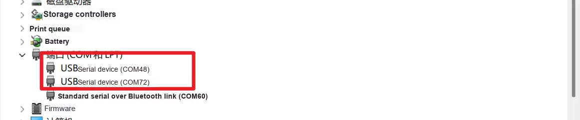
In this experiment, two sets of LoRa communication nodes are used for two-way communication testing. Both serial ports recognized by the computer correspond to the external application main controller:
| Serial port number | External application host controller | Connected LoRa module |
|---|---|---|
| COM48 | RP2040 Pico | LoRa module with onboard RP2040-Zero |
| COM72 | RP2040-Zero | LoRa module with onboard RP2040-Zero |
It should be noted that COM48 and COM72 correspond to the USB serial ports of two external application main controllers, not the serial ports of the onboard main controller of the LoRa module.
The actual data transmission path is as follows:
COM48
RP2040 Pico external host
        │ UART
        ▼
LoRa module A onboard RP2040-Zero
        │ SPI
        ▼
E22 module A
        ))) LoRa wireless communication (((
E22 module B
        ▲ SPI
        │
LoRa module B onboard RP2040-Zero
        ▲ UART
        │
RP2040-Zero external host
COM72- Demo 1: Continuous Data Transmission via COM72 and Reception via COM48
Screen Recording 2026-08-24 193631.mp4 15.6 MB
In this demonstration:
COM72The connected RP2040-Zero serves as the transmitting end;COM48The connected RP2040 Pico serves as the receiving end;- The transmitting end continuously sends numbered test data packets;
- The receiving end receives data in sequence and displays the data content, RSSI and SNR.
COM72 (RP2040-Zero sender)
              │
              │ Send data continuously
              ▼
        LoRa wireless link
              │
              ▼
COM48 (RP2040 Pico receiver)
This experiment is used to verify the continuous data transmission capability from the RP2040-Zero node to the RP2040 Pico node.
- Demonstration 2: Continuous Data Transmission via COM48 and Reception via COM72
Screen Recording 2026-08-24 193813.mp4 18.5 MB
This demo swaps the transmit and receive roles of the two nodes:
COM48The connected RP2040 Pico serves as the transmitting end;COM72The connected RP2040-Zero serves as the receiving end;- The Pico node continuously transmits test data packets with sequence numbers;
- The Zero node receives and verifies the content of the data packet.
COM48 (RP2040 Pico sender)
              │
              │ Send data continuously
              ▼
        LoRa wireless link
              │
              ▼
COM72 (RP2040-Zero receiver)
This experiment is used to verify the reverse continuous data transmission capability from the RP2040 Pico node to the RP2040-Zero node. The two directional tests jointly verify that the LoRa link has bidirectional communication capability.
- Demo 3: Bidirectional Transmission of Arbitrary Data
Screen Recording 2026-08-24 193920.mp4 24.4 MB
In this demonstration, the transmitting end and receiving end are no longer fixed. The external main controllers connected to both COM48 and COM72 can input and send arbitrary text data.
COM48 (RP2040 Pico)
        ⇄ UART ⇄ LoRa module A

        ⇄ LoRa wireless link ⇄

        LoRa module B ⇄ UART ⇄
COM72 (RP2040-Zero)
After data is entered on the COM48 terminal, the data is sent to COM72 via the LoRa link; conversely, data entered on the COM72 terminal can also be sent back to COM48.
This experiment is designed to verify the following:
- Both nodes are capable of transmitting and receiving data.
- The communication direction can be dynamically switched;
- Any UTF-8 text can be sent;
- The UART command bridge and the LoRa wireless link can implement two-way interactive communication.
IV. Drivers
lora_driver.zip 37 KB
5. BOM & Recommended Alternative Parts
To obtain BOM and recommended alternative parts, please follow our official account [Freak Embedded]
VI. Revision History
Document Version | Date of Revision | Modifier | Modify Content |
v1.0 | 2026-8-24 | Mi Ming Xuan | Initialize the document |
v1.1 | 2026-8-26 | Li Zisheng | The hardware engineering is not yet completed. |
VII. Relevant Materials
7.1 Chip Datasheet
E22-M_Series_Module_UserManual_CN.pdf 1.9 MB
E22.pdf 1.3 MB
7.2 Unique Icons for PCB Silk Screen