
Contents
- I. Module Introduction
- II. Introduction to Major Chips
- 2.1 Chip Overview
- 2.2 Pin Definition
- 2.3 Functional Block Diagram
- 2.4 Performance Parameters
- 2.5 Reference Circuit
- 2.6 Chip Configuration
- 2.7 Communication Interfaces and Related Protocols
- 2.8 PCB Routing Notes
- III. Instructions for Circuit Engineering and Module Usage
- 3.1 Circuit Source Engineering
- 3.2 Module Usage Instructions
- 3.3 Application Experiment
- IV. Drivers
- 5. BOM & Recommended Alternative Parts
- VI. Revision History
- VII. Relevant Materials
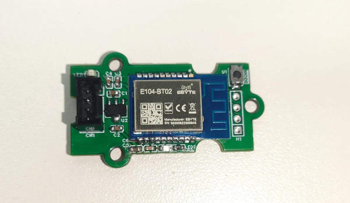
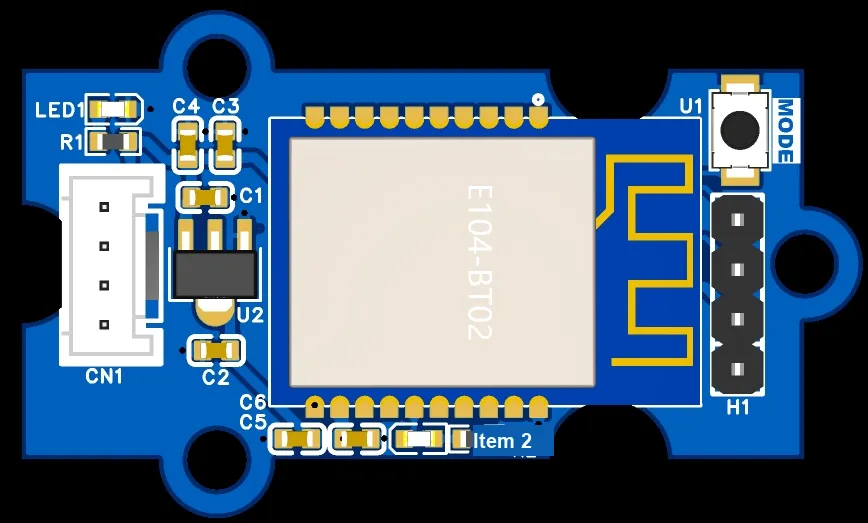
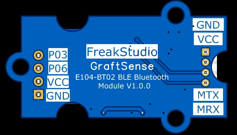
I. Module Introduction
The BLE Bluetooth module based on E104-BT02 implements Bluetooth communication function via the E104-BT02 UART-to-BLE module. Based on the Dialog DA14580 solution, this module operates in the 2.4GHz ISM frequency band, and integrates BLE protocol stack, broadcasting and connection management, transparent transmission, and UART command configuration functions. The operating voltage of the module is 2.5~3.6V, and 3.3V power supply is recommended; the customized baseboard of this project takes + 5V as input, and supplies power to the module after voltage regulation via AMS1117-3.3V.
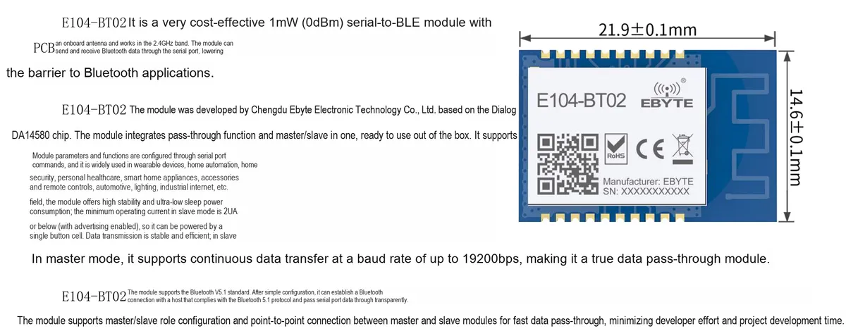
This module supports role switching between host and slave. Users can exchange data with an external MCU via UART, and modify parameters related to device name, baud rate, advertising, UUID, MTU, MAC binding and power consumption in configuration mode. By default, the module works in slave role with advertising enabled, UART configured as 19200bps, no parity and 1 stop bit, which is applicable to scenarios such as smart home, industrial telemetry, automatic data acquisition, wearable devices and BLE human-machine interaction.
- Supports the BLE 5.1 standard and is compatible with common BLE Central devices.
- It supports the integration of master and slave functions, and the master can connect up to 2 slave modules at maximum.
- Supports UART transparent transmission, with default parameters of 19200bps and 8N1.
- It supports low-power sleep, serial port wake-up, data validity indication and connection status indication.
- It supports 16-bit/128-bit UUIDs, MTU ranging from 20 to 128 bytes, Beacon/iBeacon advertising and Bluetooth sniffing.
- It comes with a built-in PCB onboard antenna, and the module measures approximately 14.6mm × 21.9mm in dimensions.
II. Introduction to Major Chips
This module is designed with the E104-BT02 BLE serial communication module, and its core solution is Dialog DA14580. The module has internally completed the functions of radio frequency, protocol stack and serial port transparent transmission, so the external main controller does not need to directly configure the registers of DA14580, and only needs to control the MODE, WKP, RESET_H and UART interfaces according to this manual.
2.1 Chip Overview
DA14580 is an SoC solution designed for Bluetooth Low Energy applications. Built on this foundation, the E104-BT02 integrates BLE protocol processing, UART transparent transmission, and parameter storage. The official product datasheet currently describes this module as supporting BLE 5.1, while earlier specification summaries still list it as BLE 4.2. Therefore, the firmware version of the module should be recorded simultaneously for certification, interoperability testing, and production traceability purposes.
2.2 Pin Definition
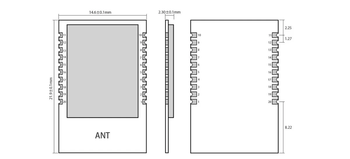
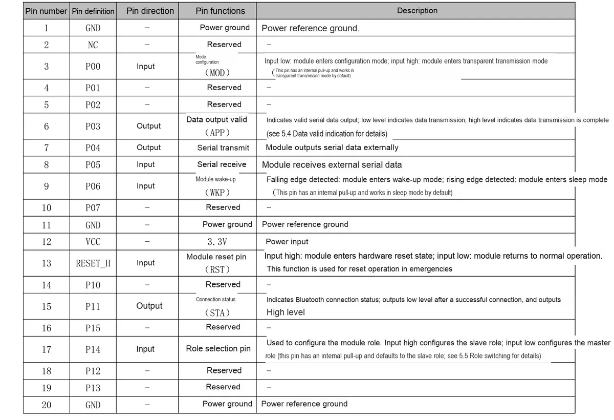
The E104-BT02 is a 20-pin SMD module with a 1.27mm pitch. The table below is compiled based on the official product specification, and the reserved pins including P01, P02, P07, P10, P12, P13 and P15 must not be connected to external logic.
2.3 Functional Block Diagram
The official documentation does not provide a detailed internal block diagram of the DA14580. Based on the external functions of the E104-BT02, the module can be abstracted into a data path of "UART interface → module firmware → BLE protocol stack / GATT → RF antenna". P00/MOD, P06/WKP, RESET_H and P14 are responsible for module status, wake-up, reset and role initialization, while P03/APP and P11/STA provide status output.
functional unit | Input | Output / Function |
UART pass-through | P05 / MRX | P04 / MTX; Bidirectional Data Transfer between UART and BLE |
BLE protocol stack | Broadcasting, Scanning and Connection Parameters | GATT services, Notify / Write, Beacon |
Mode Control | P00 / MOD, P06 / WKP | Pass-through, AT configuration, sleep, wake-up |
Status Output | Internal State of the Module | P03 Data Valid, P11 Connection Status |
Parameter Storage | AT Command | Device name, baud rate, MTU, UUID and other parameters are saved after power-off |
2.4 Performance Parameters
The following table lists the main performance parameters of the E104-BT02; the values are taken from the official E104-BT02 product datasheet, and the typical values are affected by advertising, connection, LED load, power supply and PCB layout.
Performance | minimum value | Typical Value | Maximum Value / Remarks |
Power Supply Voltage | 2.5V | 3.3V | 3.6V; exceeding 3.6V may cause damage |
communication level | GND | 3.3V | 5V TTL poses a risk of damage |
Operating Frequency Band | 2379MHz | - | 2496MHz |
emission current | - | 3.4mA | Typical Value |
Receive current | - | 3.7mA | The software shutdown conditions vary |
quiescent current | - | 3μA | Typical value; state-dependent |
Transmit Power | - | 0dBm | 1mW |
Receive Sensitivity | -93.5dBm | -94dBm | -94.5dBm |
Reference Distance | - | 70m | Clear and open environment, with a height of approximately 2.5 meters |
Bluetooth protocol | - | BLE 5.1 | The early summary document states BLE 4.2 |
Overall Dimensions | - | 14.6 × 21.9mm | Surface mount type, 1.27mm pitch |
2.5 Reference Circuit
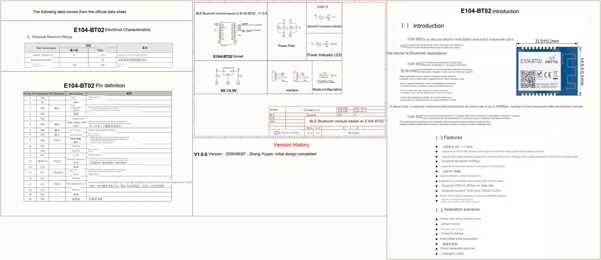
The reference circuit of the custom baseboard for this project consists of a + 5V input, 3.3V voltage regulator, power filtering, E104-BT02 module, UART/wake-up interface, MODE control, connection status indicator and power indicator. The schematic diagram is shown as follows:
2.5.1 5V and 3.3V Power Supply Conversion Section
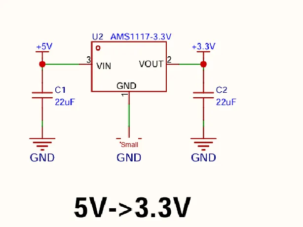
U2 adopts the AMS1117-3.3V regulator, which converts the + 5V input from the baseboard to the + 3.3V required by the module. Capacitors including C1 and C2 are used for input/output filtering and power supply decoupling of the module. During design, it is necessary to check the dropout voltage, heat generation and power-on overshoot of the regulator to ensure that the VCC of the module does not exceed 3.6V.
2.5.2 E104-BT02 Module Section
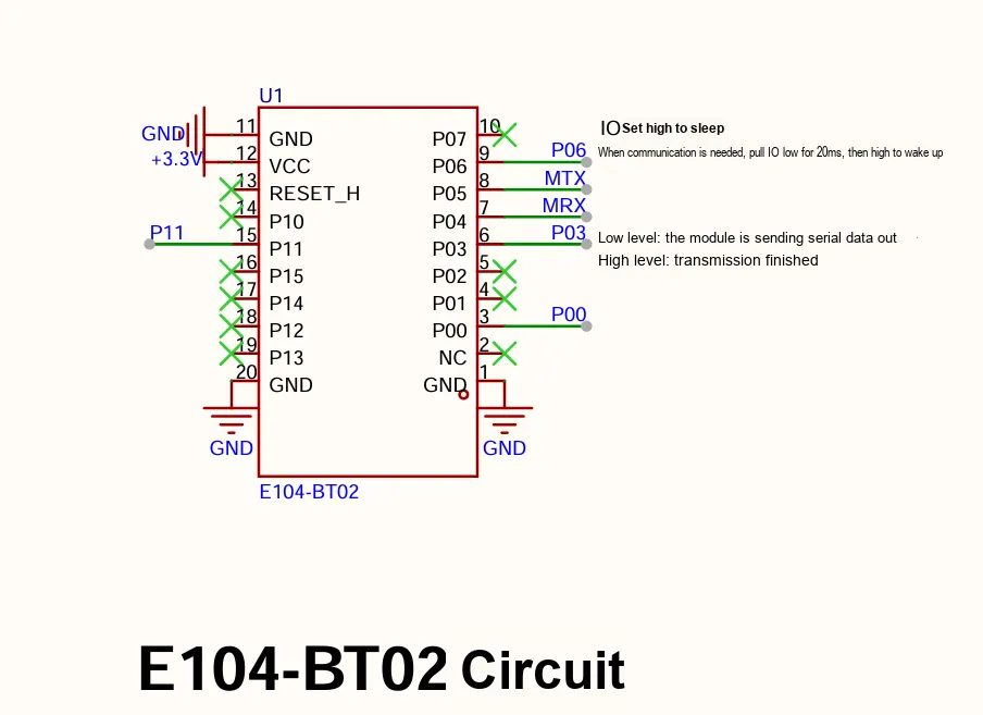
E104-BT02 serves as the core functional device: VCC is connected to + 3.3V, GND to the system ground; P04/P05 are responsible for UART communication, P06 functions as the wake-up pin, P00 serves as the mode control pin, and P11 is connected to the status output. The reserved pins shall be left floating in accordance with the official pin definition.
2.5.3 Buttons and Indicator Lights Section
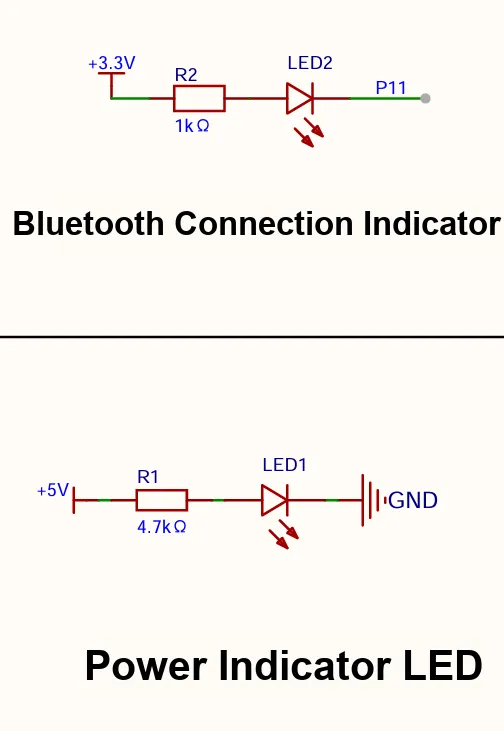
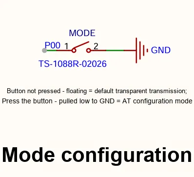
In the schematic, LED1 serves as the + 5V power indicator, and LED2 is driven by the P11 network to indicate the Bluetooth connection status. When the MODE-related key or interface pulls P00 low, the device enters AT configuration mode; when released, it reverts to transparent transmission. The LED current shall be included in the low power consumption test.
2.5.4 External Interface Section
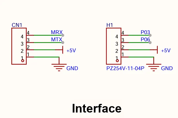
In the schematic diagram, CN1 is marked as a 4-pin connector with the network names + 5V, P06, MTX and MRX; H1 is the interface/key connection related to MODE. Before mass production, the Pin1 orientation and wire sequence shall be supplemented in the PCB silkscreen and assembly drawing to avoid misjudgment of the connector orientation.
2.6 Chip Configuration
E104-BT02 is a Plug and Play module, which requires no external configuration of the DA14580 registers. All common configurations are completed via UART AT commands and saved inside the module after successful configuration. Before executing AT commands, you must wake up the module and pull P00/MOD low.
Configuration Item | default value | Description |
UART | 19200 bps / No Parity / 1 Stop Bit | The main control serial port must be matched |
Character | Slave | P14: High level or floating |
Device Name | E104-BT02 | Up to 18 bytes of ASCII |
broadcast | On / 1s | Slave device waiting for connection |
MTU | 20 bytes | Configurable in the range of 20 to 128, to take effect upon the next connection |
Data Output Indicator | Turn on | P03 Output Low Level Indicator |
2.7 Communication Interfaces and Related Protocols
2.7.1 Introduction to the Principle of Serial Port Transparent Transmission
With the built-in E104-BT02 as the core, the module encapsulates the data stream sent by the external MCU via UART into BLE data for wireless transmission; meanwhile, it restores the data received via BLE into a UART data stream and outputs it to the MCU. The module does not parse the content of user data, and only realizes the bidirectional transparent conversion among "serial port electrical signal → BLE wireless data → serial port electrical signal".
Data Direction | Module Pins | Main Control Connection |
Main controller → BLE | P05 / MRX | Main Control TX → E104 P05 |
BLE → Main Controller | P04 / MTX | E104 P04 → Main Control RX |
Valid Data | P03 / APP | A low level indicates that the module is outputting serial port data |
Connection Status | P11 / STA | A low level indicates that BLE is connected |
2.7.2 AT Command Related
AT commands uniformly follow the <command> format, with no additional CR, LF or CRLF appended. Common commands in configuration mode are listed below:
Instruction | Function | Note |
<RESET> | Reset the protocol stack | Not equivalent to hardware RESET_H |
<RESTORE> | Restore factory parameters | High-impact operation |
<BAUD19200> | Set UART baud rate | Takes effect after exiting the configuration |
<COMBAUD> | Read baud rate | Return current configuration |
<NAMExxx> | Set device name | Up to 18 bytes of ASCII |
<MNAME> | Read the device name | Return the device name |
<ADVON> / <ADVOFF> | Turn Broadcast On / Off | Slave Role Usage |
<STATE> | Read connection status | Connection status is valid |
<MAC> | Read local MAC address | Returns the hexadecimal address |
<DISCONNECT> | Disconnect the current connection | active disconnect |
<MTUxxx> | Set MTU | 20~128, take effect upon next connection |
<COMWKPON> | Enable serial port wake-up | RX falling edge wake-up |
<APPON> / <APPOFF> | Control Data Valid Indication | Impact P03 |
<PWDxxxxxx> | Air Configuration Certification | Default: 123456 |
E104-BT02_AT_Manual.pdf 1.7 MB
Instruction Discrepancies: The AT manuals, product specifications, and early Specification documents originate from different historical versions; prior to software integration, the actual firmware echo shall prevail, and the firmware version and abnormal returns shall be recorded.
2.8 PCB Routing Notes
- The area under and around the onboard antenna region shall be kept clear as officially recommended, with no copper pouring or traces routed therein.
- Place the end of the antenna close to the edge of the base plate to avoid being blocked by metal enclosures, batteries, screws, shielding covers and high-speed digital lines.
- Multi-point reflow for module GND, place power filter capacitors close to VCC/GND; do not route UART and LED lines across the antenna area.
- After changing the module orientation, antenna clearance, enclosure material or grounding structure, the distance, RSSI, throughput and reconnection shall be retested.
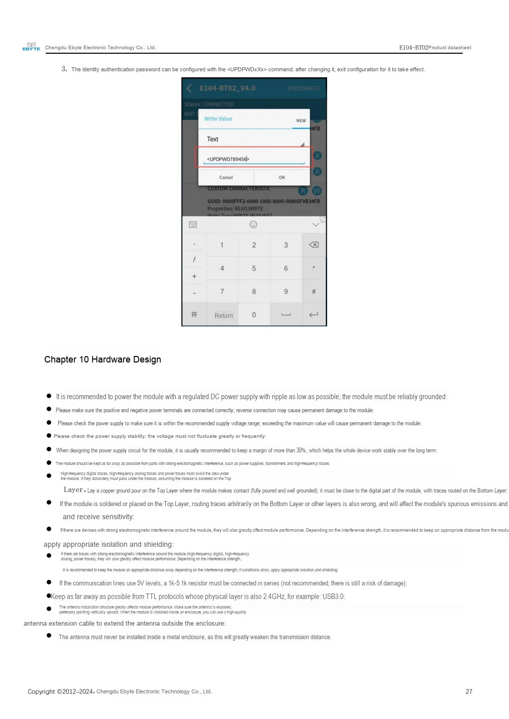
Figure 2-4 Hardware Design and PCB Notes in Official Documentation
III. Instructions for Circuit Engineering and Module Usage
3.1 Circuit Source Engineering
To obtain the source code of the circuit, please follow the official account [Freak Embedded]
3.2 Module Usage Instructions
When using this module, you need to pay attention to the UART direction, MODE configuration level and WKP wake-up status at the same time. The hardware connection suggestions are as follows:
E104-BT02 | Custom Baseboard / Main Controller | Description |
P04 / MTX | Main Control UART RX | E104 → Main Controller |
P05 / MRX | Main Control UART TX | Main Control → E104 |
P00 / MOD | Mode Control | LOW configuration, HIGH/floating pass-through |
P06 / WKP | Wake-up Control | wake-up on falling edge, sleep on rising edge |
VCC / GND | 3.3V / common ground | Do not connect 5V logic to the IO |
The verified RP2040 wiring uses UART0: GP16 TX → carrier board MTX/TX → E104 P05 RX; E104 P04 TX → carrier board MRX/RX → GP17 RX. Note that GP16/GP17 here are only for test wiring and are not mandatory GPIO configurations for the driver.
Special Note: The network names of the carrier board in this project are named from the perspective of the main controller: the MTX/TX network is connected to module P05 (module RX), and the MRX/RX network is connected to module P04 (module TX). Please refer to the actual schematic diagram network for connection, and do not make cross-connections solely based on the network names.
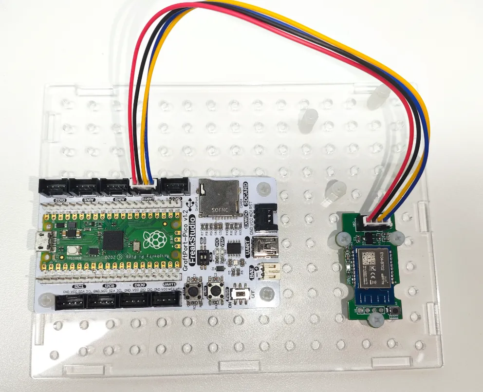
Here, we first use the HY2.0-4P connection cable to connect the module to the GraftPort-RP2040 development board's UART0 interface:
The module connections are shown in the following table:
Development Board Pins | Module Pins | Description |
Pin 16 |
|
|
Pin 17 |
|
|
3.3 Application Experiment
Taking Raspberry Pi Pico / RP2040, MicroPython and mobile phone BLE Central as examples below, we will complete AT query and BLE/UART bidirectional transparent transmission. Before the experiment, please confirm that the module is powered normally, the main controller and the module share the same ground, and prepare the connection that can control P00/MOD.
Here, we need to search for the relevant driver packages on uPyPI: https://upypi.net/zh/
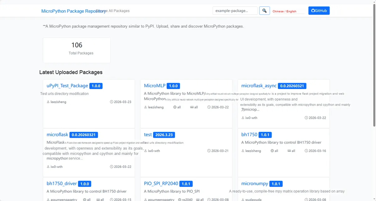
Enter e104bt02_driver to search, and the following will be displayed:
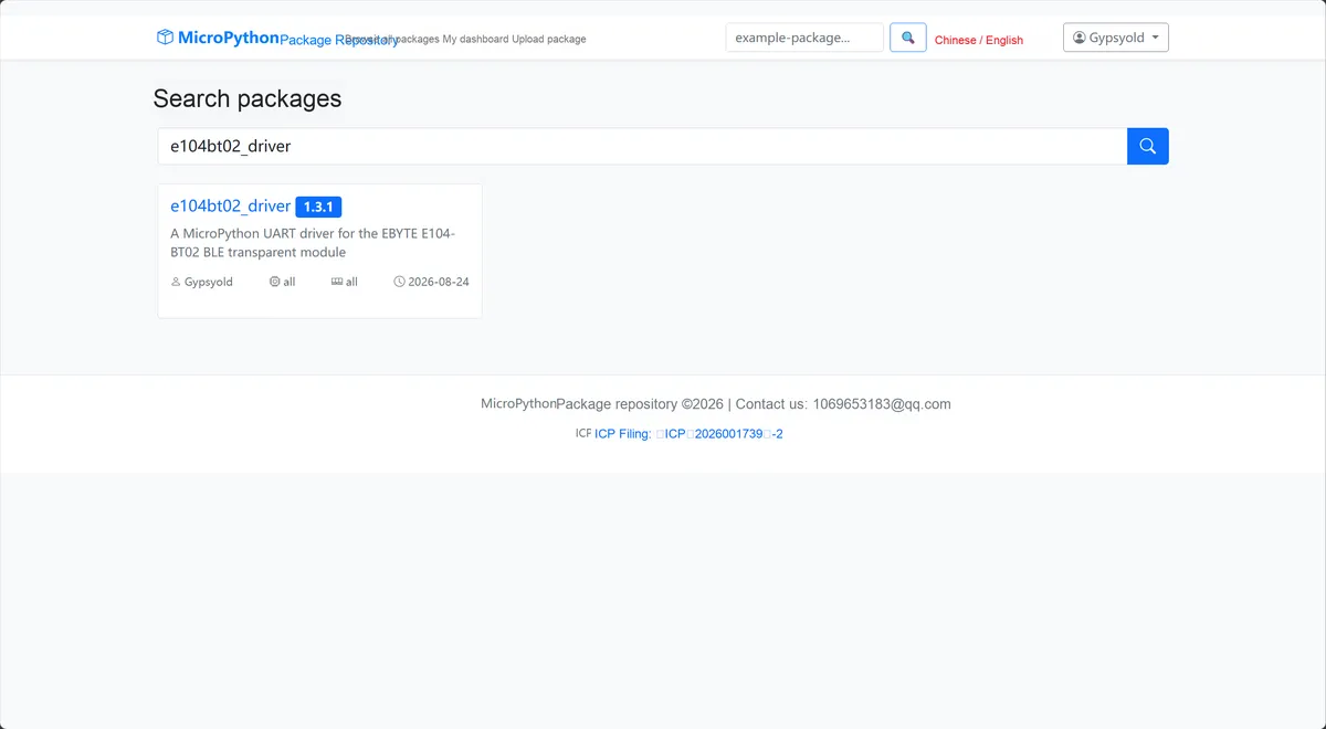
Click to copy the local installation command:
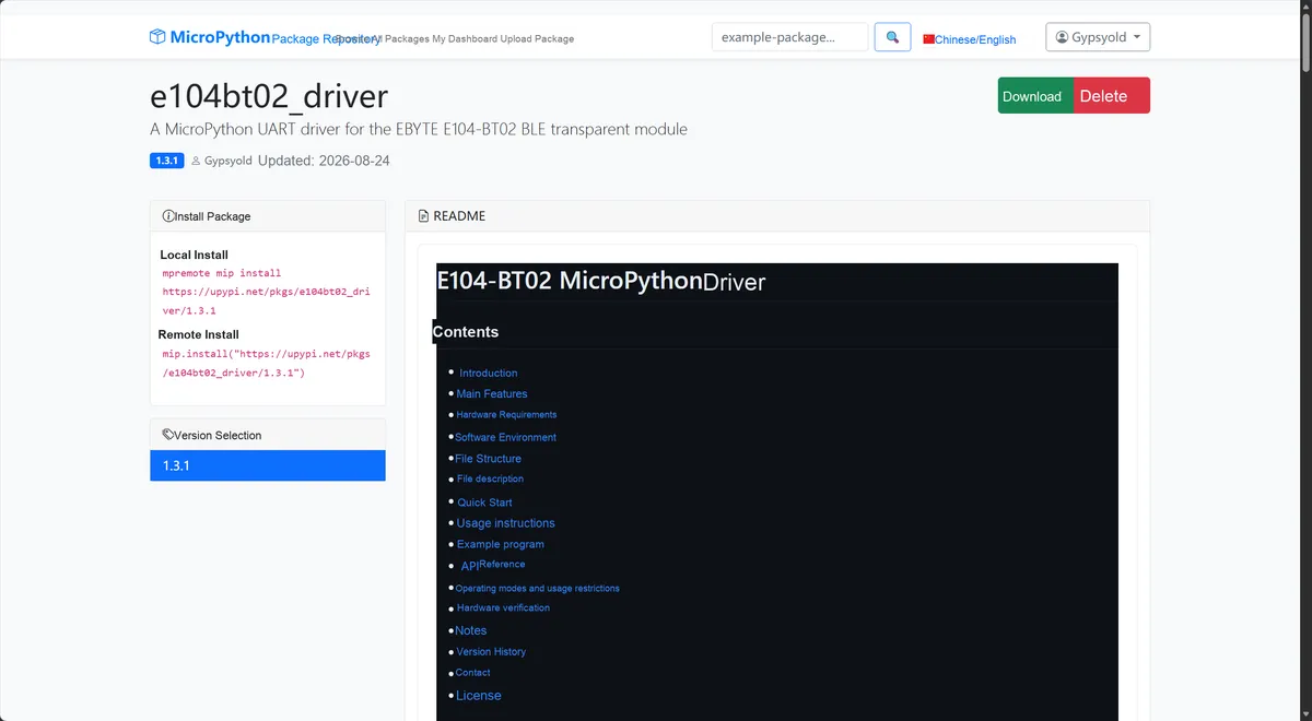
Here, we can import the module driver library code via the mip tool. The usage commands for the mpremote tool are as follows:
mpremote mip install https://upypi.net/pkgs/e104bt02_driver/1.3.1After importing the driver code of EBYTE's E104-BT02 Wi-Fi serial communication module, copy the following main.py code into our project:
# Python env   : MicroPython v1.23.0
# -*- coding: utf-8 -*-
# @Time    : 2026/08/18
# @Author  : FreakStudio
# @File    : main.py
# @Description : E104-BT02 basic query and transparent transfer example
# @License : MIT

# ======================================== Import Modules =========================================

import time
from machine import Pin, UART

from e104bt02 import E104BT02, E104BT02Error

# ======================================== Global Variables ============================================

UART_ID = 0
UART_TX_PIN = 16
UART_RX_PIN = 17
UART_BAUDRATE = 19200
UART_PARITY = None
UART_STOP_BITS = 1
MODE_RELEASE_WAIT_SECONDS = 15
TRANSPARENT_READ_TIMEOUT_MS = 200
LOOP_DELAY_SECONDS = 0.05
UART_TO_BLE_PAYLOAD = b"Hello from RP2040"

# ======================================== Functions ============================================

# ======================================== Custom Classes ============================================

# ======================================== Initialization configuration ===========================================

time.sleep(3)
print("FreakStudio: E104-BT02 test")
print("Keep P06/WKP in the verified awake state.")
print("Hold MODE so P00/MOD is low for AT queries.")

# Use the RP2040 UART wiring already verified on real hardware.
uart0 = UART(
    UART_ID,
    baudrate=UART_BAUDRATE,
    tx=Pin(UART_TX_PIN),
    rx=Pin(UART_RX_PIN),
    parity=UART_PARITY,
    stop=UART_STOP_BITS,
)

# Inject the UART object created by the caller into the official driver.
module = E104BT02(uart0)

# ========================================  Main program ============================================

try:
    # In configuration mode, only run representative safe queries.
    print("baudrate=%d" % module.get_baudrate())
    print("module_name=%s" % module.get_module_name())
    print("state=%s" % module.get_state())
    print("mtu=%d" % module.get_mtu())
    print("role=%s" % module.get_role())
    print("mac=%s" % module.get_mac())

    # MODE is released manually by the user; the wait time is only an example operation window, not official timing.
    print("Release MODE now so P00/MOD becomes high.")
    print("Connect E104-BT02 from the BLE central.")
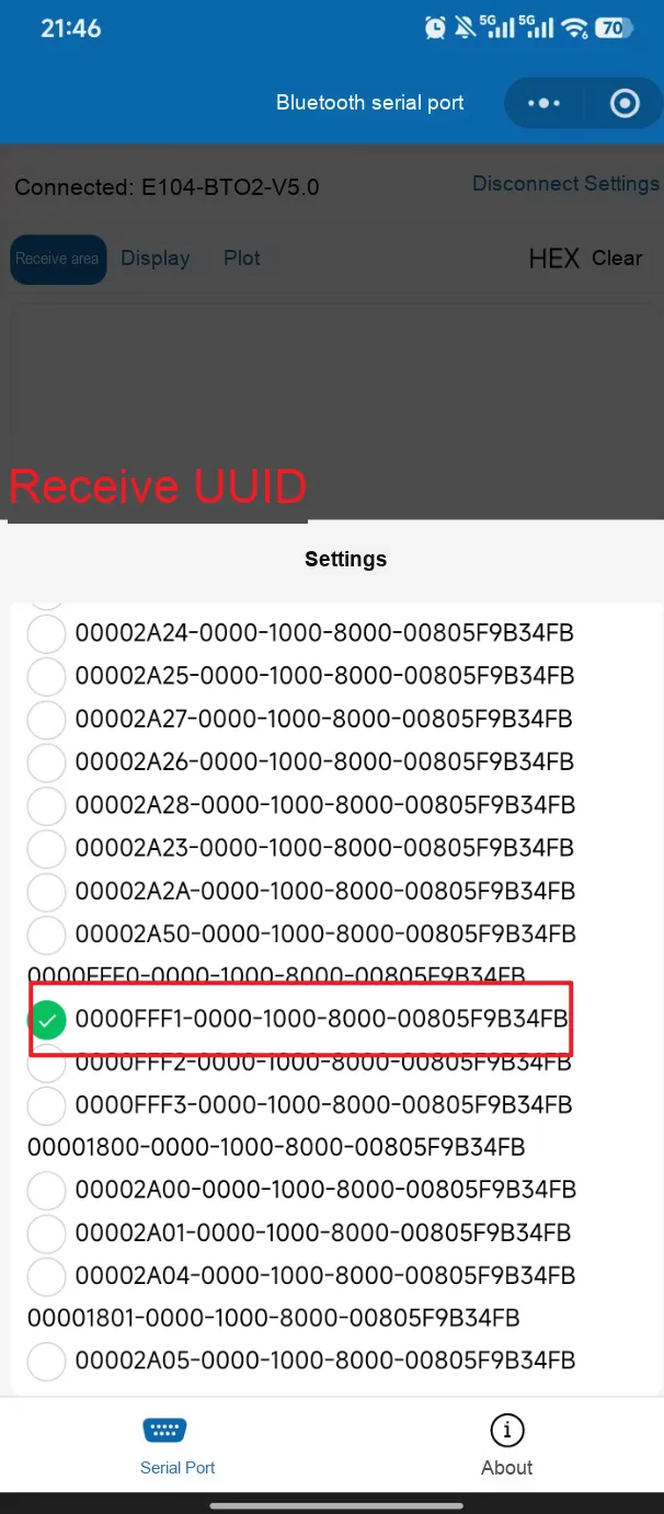
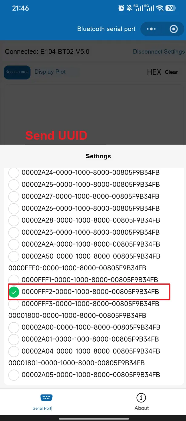
    print("Enable FFF1 Notify.")
    print("Use FFF2 Write to send BLE data to RP2040.")
    for remaining in range(MODE_RELEASE_WAIT_SECONDS, 0, -1):
        print("Transparent mode starts in %d second(s)." % remaining)
        time.sleep(1)

    # After entering the transparent phase, no more AT queries are sent.
    print("UART -> BLE")
    print("TX: %s" % repr(UART_TO_BLE_PAYLOAD))
    written = module.send(UART_TO_BLE_PAYLOAD)
    print("TX bytes: %d" % written)

    while True:
        # Read with a finite timeout to avoid blocking the main loop forever.
        data = module.read(timeout_ms=TRANSPARENT_READ_TIMEOUT_MS)
        if data:
            print("BLE -> UART")
            print("RX: %s" % repr(data))
            print("RX bytes: %d" % len(data))

            # Echo the received data back unchanged to demonstrate bidirectional transparent communication.
            print("UART -> BLE echo")
            print("TX: %s" % repr(data))
            echo_written = module.send(data)
            print("TX bytes: %d" % echo_written)
        time.sleep(LOOP_DELAY_SECONDS)

except KeyboardInterrupt:
    print("Program interrupted by user")
except OSError as err:
    print("Hardware communication error: %s" % str(err))
except Exception as err:
    if isinstance(err, E104BT02Error):
        print("E104-BT02 driver error: %s" % str(err))
    else:
        print("Unexpected error: %s" % str(err))
finally:
    print("Cleaning up resources...")
    # The driver only releases its UART reference; the UART hardware is closed by this example.
    module.close()
    uart0.deinit()
    del module
    del uart0
    print("Program exited")
To flash the code, open a terminal and use the mpremote tool to connect to the main controller, then run main.py
- Keep P06/WKP in the wake-up state.
- Press and hold MODE to set P00/MOD to low level.
- Read the module's baud rate, name, status, MTU, role and MAC address.
- Release MODE to restore P00/MOD to high level.
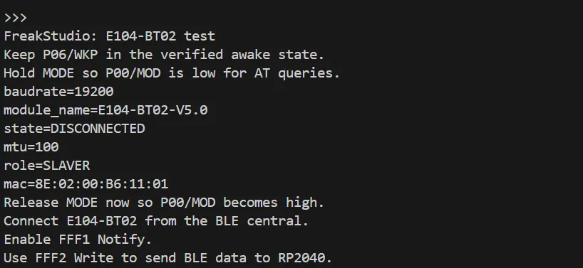
| Item | Result |
|---|---|
| UART baud rate | 19200bps |
| Module Name | E104-BT02-V5.0 |
| Bluetooth status | DISCONNECTED |
| MTU | 100 |
| Working role | SLAVER |
| MAC address | 8E:02:00:B6:11:01 |
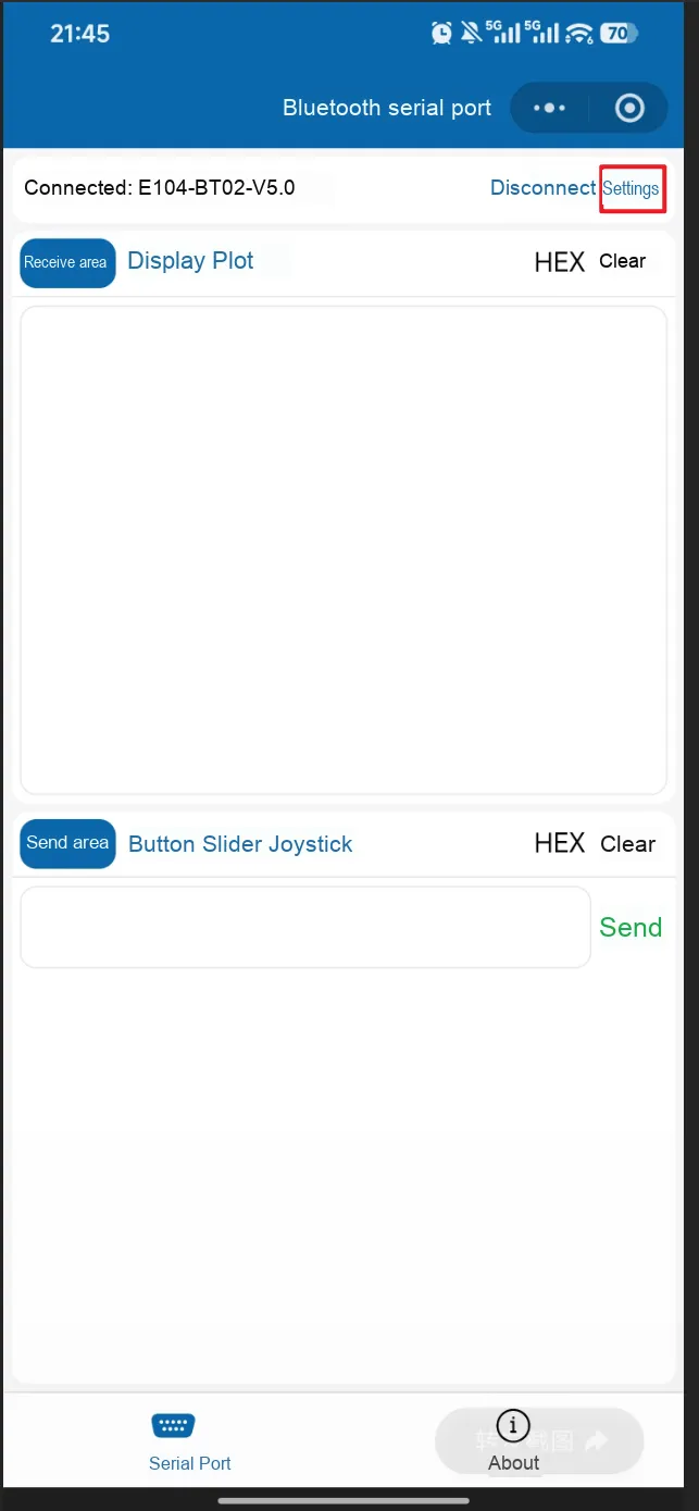
- Open the WeChat Mini Program (Bluetooth Serial Port - Jiangxie Technology).

- Use the Bluetooth assistant to connect to E104-BT02.
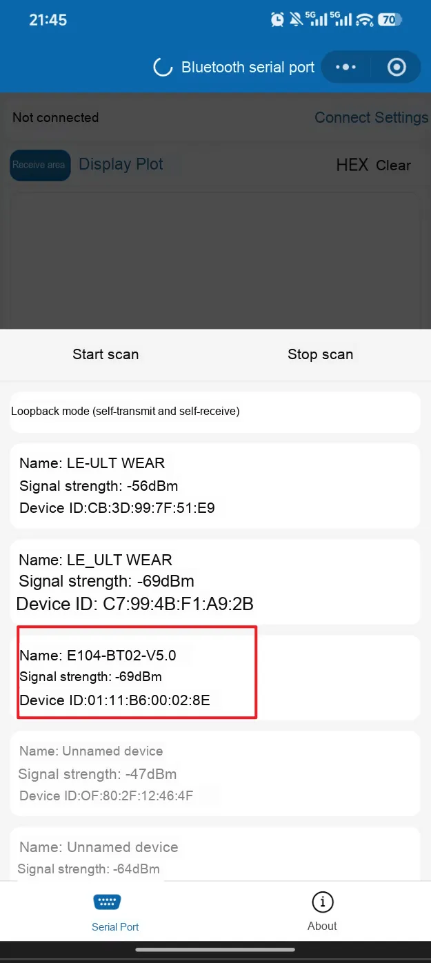
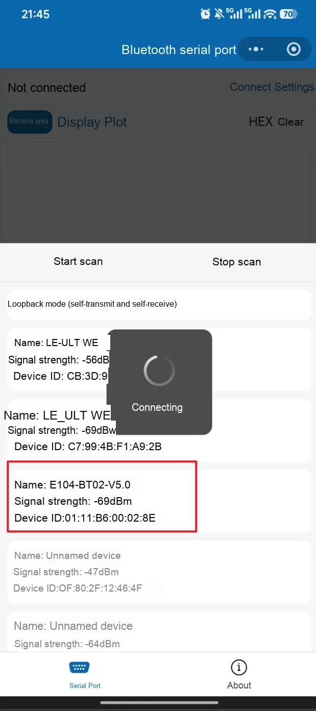
- Set the receiving and transmitting UUIDs
- Check the operation status of both parties
Demo Video.mp4 17.2 MB
IV. Drivers
e104bt02_driver.zip 17 KB
5. BOM & Recommended Alternative Parts
VI. Revision History
Document Version | Date of Revision | Modifier | Modify Content |
v1.0 | 2026-8-20 | Mi Ming Xuan | Initialize the document |
v1.1 | 2026-8-26 | Li Zisheng | The circuit engineering hasn't been arranged yet |
VII. Relevant Materials
E104-BT02_AT_Manual.pdf 1.7 MB
E104-BT02_Datasheet_CN.pdf 1.5 MB
E104-BT02_Specification.pdf 1.4 MB