
Contents
- I. Module Introduction
- II. Introduction to Major Chips
- 2.1 Chip Overview
- 2.2 Pin Definition
- 2.3 Functional Block Diagram
- 2.4 Performance Parameters
- 2.5 Reference Circuit
- 2.6 Chip Configuration
- 2.7 Communication Interfaces and Related Protocols
- 2.8 PCB Routing Notes
- III. Instructions for Circuit Engineering and Module Usage
- 3.1 Circuit Source Engineering
- 3.2 Module Usage Instructions
- 3.3 Application Experiment
- 4. Drivers
- 5. BOM & Recommended Alternative Parts
- VI. Revision History
- VII. Relevant Materials
I. Module Introduction
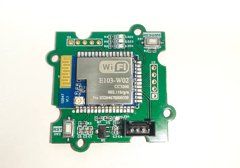
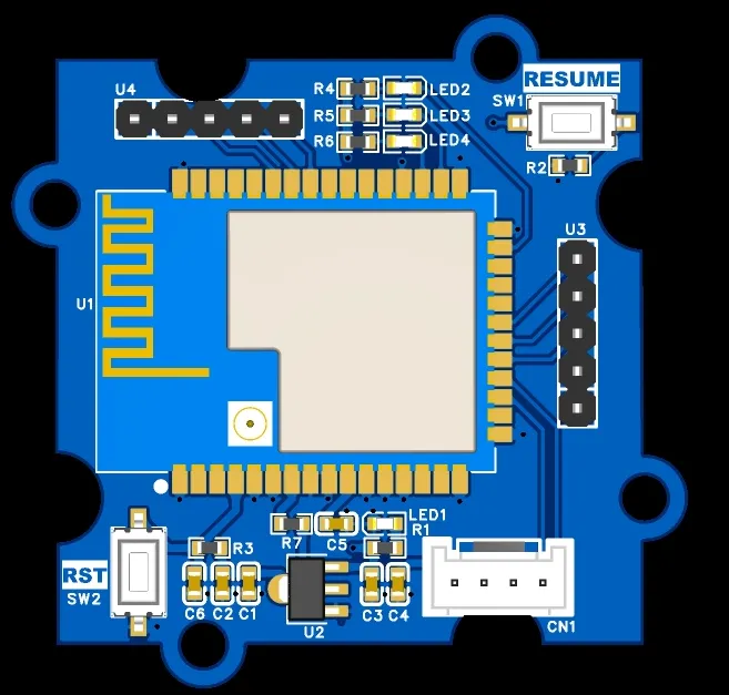
The Wi-Fi serial communication module based on Ebyte E103-W02 takes the E103-W02 wireless module as the core, adopts the TI CC3200 chip at the bottom layer, and operates in the 2.4-2.484 GHz frequency band. This module integrates the Wi-Fi protocol stack, TCP/IP network capabilities and UART serial interface, allowing the external main controller to complete parameter configuration and network data transceiving via the serial port.
This design uses + 5V as the input power supply of the base board, which is converted via AMS1117-3.3V to power the E103-W02, and provides reset, factory reset, Wi-Fi connection, network connection, SmartConfig status indication and GPIO expansion interfaces. The module supports AP/STA network roles, as well as operating modes including NORMAL, MQTT, HTTP, MULTIS, and MULTIC, and is applicable to scenarios such as IoT terminals, smart homes, industrial Data Acquisition, and remote device networking.
Note: The baseboard inputs are + 5V, but the VCC and all GPIOs of the E103-W02 belong to the 3.3V power domain and cannot be directly connected to 5V logic levels.
II. Introduction to Major Chips
This module does not directly adopt the bare-chip solution, but uses the E103-W02 serial-to-Wi-Fi module from Chengdu Ebyte Electronic Technology Co. , Ltd. Internally, the E103-W02 is based on the TI CC3200, which has integrated RF, network protocol stack and serial AT command functions, and can shorten the development cycle of wireless networking products.
2.1 Chip Overview
E103-W02 is a surface-mount UART-to-Wi-Fi module that supports IEEE 802.11 b/g/n and a complete TCP/IP protocol stack. This module supports two network roles: AP and STA. Users can enter the AT command mode via the serial port to configure parameters, and it can also realize transparent transmission between serial port data and network data during operation.
According to official specifications, the E103-W02 operates at a voltage of 2.4-3.6V with a typical value of 3.3V; the module measures approximately 27 × 19 × 2.7mm, supports a maximum transmit power of 20dBm, and has an operating temperature range of -40 to + 85°C. The default serial port parameters are 115200bps, 8 data bits, no parity, and 1 stop bit.
2.2 Pin Definition
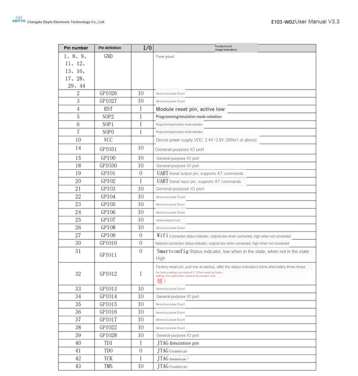
E103-W02 has a total of 44 pads, including power supply, UART, status output, factory reset, JTAG and general-purpose GPIOs. The table below lists the pins used in this design or requiring key attention; the remaining unused GPIOs shall still be handled in accordance with the requirements of the official manual.
Pin Number | Pin Definition | I/O | Functions and Instructions for Use |
1, 8, 9, 11, 12, 13, 16, 17, 28, 29, 44 | GND | - | Power Ground |
4 | RST | I | Module reset, active low |
5 / 6 / 7 | SOP2 / SOP1 / SOP0 | I | Selection of Programming and Emulation Mode |
10 | VCC | - | Power supply voltage: 2.4-3.6V, it is recommended that the power supply capacity be greater than 300mA |
19 | GPIO1 | O | UART serial port output; the network name of this board is MRX |
20 | GPIO2 | I | UART serial port input; the network name of this board is MTX |
21 / 22 / 23 | GPIO3 / GPIO4 / GPIO5 | IO | Extended by U3 |
27 | GPIO9 | O | Wi-Fi connection status, outputs low after connection |
30 | GPIO10 | O | Network connection status, outputs low level when connected |
31 | GPIO11 | O | SmartConfig status: outputs low when entering |
32 | GPIO12 | I | Factory reset input |
37 / 38 / 39 | GPIO17 / GPIO22 / GPIO28 | IO | Extended by U4 |
40 / 41 / 42 / 43 | TDI / TDO / TCK / TMS | I/O | JTAG Emulation Interface |
2.3 Functional Block Diagram
The official documentation of E103-W02 does not provide a separate internal functional block diagram. Based on the official application notes and the schematic of this design, the system functional relationship can be summarized as follows: the external + 5V power supply is supplied to E103-W02 via AMS1117-3.3V; the main controller exchanges AT commands and transparent transmission data with the module through UART; the module communicates with AP, router, server or Client via 2.4GHz Wi-Fi;GPIO9, GPIO10 and GPIO11 respectively feed back the statuses of Wi-Fi, network connection and SmartConfig.
Input/Control | Core Module | Output/Communication |
+5V → AMS1117-3.3V | E103-W02 / CC3200 | 2.4GHz Wi-Fi |
MCU UART: MTX, MRX | AT Commands and Pass-through | TCP / UDP / MQTT / HTTP |
SW2: RST; SW1: GPIO12 | Reset and Factory Reset | Status of LED2 / LED3 / LED4 |
U3 / U4 GPIO Expansion | General Purpose GPIO | External 3.3V logic device |
2.4 Performance Parameters
The table below lists the main performance parameters of the E103-W02. The relevant values are taken from the official E103-W02 manual in the folder; the actual communication distance, power consumption and throughput will be affected by the antenna, power supply, network environment and working mode.
Parameter Name | parameter value | Description |
RF chip | CC3200 | TI |
Operating Frequency Band | 2.4-2.484GHz | IEEE 802.11 b/g/n |
Module Dimensions | 27 × 19 × 2.7mm | With built-in PCB antenna |
Supply Voltage | 2.4-3.6V DC | Typically 3.3V, may be damaged if exceeding 3.6V |
power supply capacity | Above 300mA | The official recommendation is that the external LDO should be greater than 500mA |
Transmit Power | 20dBm | Approx. 100 mW |
Measured Distance | Approx. 150m | Clear and open environment, maximum power, height: 2m |
Communication Interface | UART | Supports AT commands and pass-through mode |
Default serial port | 115200bps, 8N1 | Can be modified using AT+ UART |
Operating Temperature | -40~+85℃ | Industrial-grade chip range |
Antenna type | PCB On-board Antenna / IPEX Option | Subject to the hardware version of the specific module |
2.5 Reference Circuit
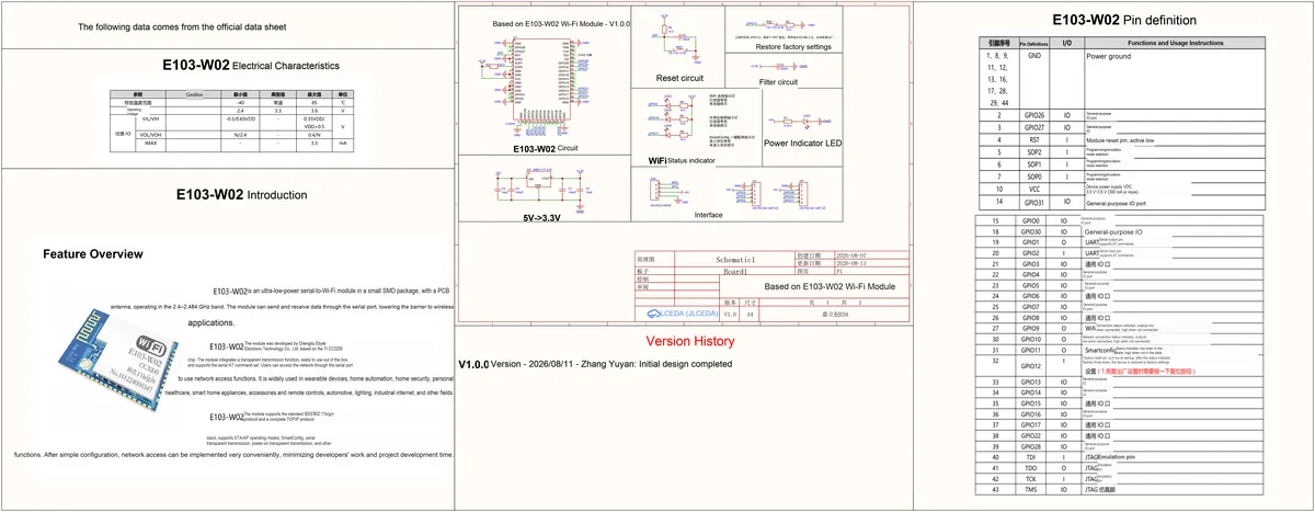
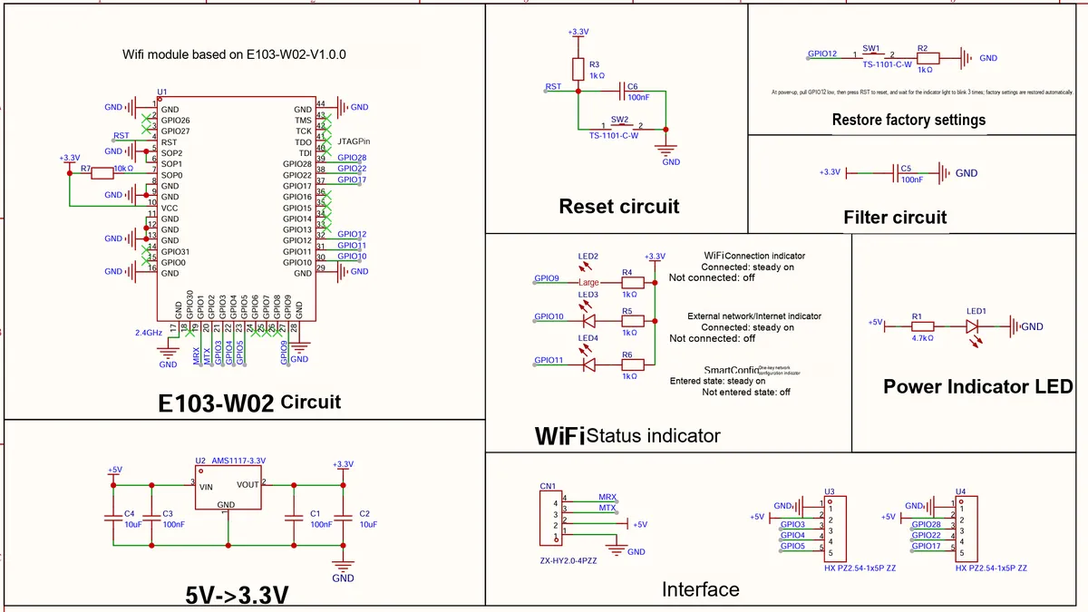
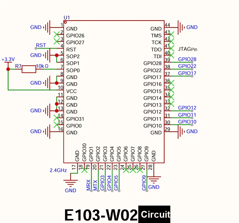
E103-W02 Module Section: U1 is the core wireless module. VCC is connected to + 3.3V, and multiple sets of GND pads are uniformly grounded; GPIO1 and GPIO2 serve as UART, GPIO9, GPIO10 and GPIO11 function as status indication outputs, and GPIO12 is used for factory reset.
5V to 3.3V Power Supply Section: U2 adopts AMS1117-3.3V to convert the + 5V input from CN1 into + 3.3V. C4 and C3 serve as input filters, while C1 and C2 act as output filters to provide stable power for the module.
Reset Circuit Section: R3 pulls RST up to + 3.3V, C6 is used for filtering, and when SW2 is pressed, RST is pulled low to perform a hardware reset.
Factory Reset Section: SW1 is connected to GPIO12. To perform a factory reset: pull GPIO12 low upon power-up, then press RST, and wait until the status LED blinks alternately three times to complete the process.
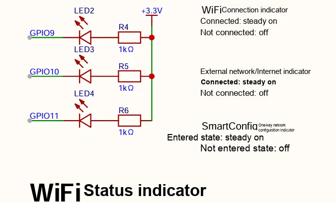
Status Indicator Section: GPIO9, GPIO10 and GPIO11 are connected to + 3.3V via LED2, LED3, LED4 and 1kΩ current-limiting resistors, and adopt a low-level activation mode to indicate the status of Wi-Fi connection, network connection and SmartConfig respectively. LED1 and R1 form the + 5V power indicator.
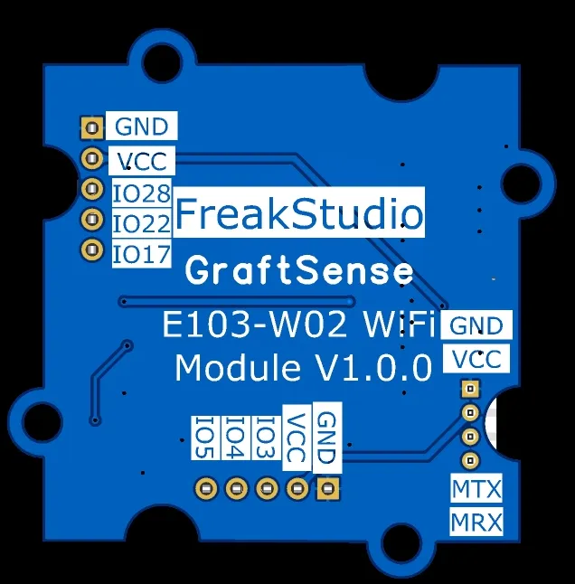
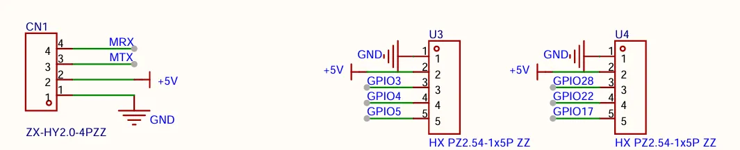
External Interface Section: CN1 provides GND, + 5V, MTX, and MRX; U3 leads out GPIO3, GPIO4, and GPIO5, while U4 leads out GPIO28, GPIO22, and GPIO17. All GPIOs operate on 3.3V logic.
2.6 Chip Configuration
The E103-W02 is a Plug and Play UART-to-Wi-Fi module, which eliminates the need for users to directly configure the CC3200 registers. Module parameters are set via UART AT commands. To enter AT mode, send "+++" without adding a carriage return or line feed; after entering AT mode, all other AT commands require a carriage return and line feed. Once configuration is complete, reset the module or power it off and back on as instructed to activate the parameters.
+++
AT+VER=?
AT+ROLE=?
AT+MODE=?
AT+UART=?
AT+STATUS=?
AT+EXIT
When the module is restored to factory settings, it normally operates in AP + NORMAL mode. Before formal use, you should read the AT+ ALLSTATE command or query each item one by one to prevent old configurations from affecting the test results.
2.7 Communication Interfaces and Related Protocols
2.7.1 Introduction to the Principle of Serial Port Transparent Transmission
The external MCU sends data to the E103-W02 via UART. The module encapsulates the serial port data and sends it to the TCP/UDP peer end according to the current Socket and network role; the data received from the network side is restored to UART data for output. In the transparent transmission mode, the main control does not need to process the Wi-Fi protocol stack, and only needs to maintain the serial port data format and service protocols.
This board adopts the naming convention based on the main controller perspective: MTX corresponds to the main controller transmit end, connected to GPIO2 (UART input) of the module; MRX corresponds to the main controller receive end, connected to GPIO1 (UART output) of the module. Therefore, when connecting to an MCU, MTX is directly connected to MCU_TX and MRX is directly connected to MCU_RX, no cross-connection is required again.
2.7.2 Network Roles and Working Modes
mode | Key Functions | Typical Use |
NORMAL | Single-channel TCP Server, TCP Client or UDP; supports remote AT commands | Serial port transparent transmission, LAN/public network data transmission |
MQTT | MQTT Client; supports Topic subscription and reporting | IoT Platform Access |
HTTP | HTTP Client; supports GET and POST | Web API Data Reporting |
MULTIS | TCP Server, allowing up to 4 TCP Client connections at maximum | Multi-Client Local Access |
MULTIC | Act as a TCP/UDP Client to connect to two servers | Dual servers or redundant links |
2.7.3 Common AT Commands
Instruction | Functions |
+++ | Enter AT mode, no carriage return or line feed added |
AT+ROLE=AP / STA | Set the network role of AP or STA |
AT+MODE=NORMAL / MQTT / HTTP / MULTIS / MULTIC | Set the operation mode |
AT+STA=<SSID>,<SecType>,<Password> | Set the hotspot to which the STA needs to connect |
AT+AP=<SSID>,<SecType>,<Password> | Configure AP Parameters |
AT+SOCK=<Protocol>,<CS>,<RemoteIP>,<RemotePort>,<LocalPort> | Set up the main Socket |
AT+UART=<Baud>,<Databit>,<Parbit>,<Stopbit> | Configure serial port parameters |
AT+SMT=<Timeout> | Enter SmartConfig |
AT+RESTORE | Restore factory settings |
AT+RST | Restart Module |
2.8 PCB Routing Notes
The E103-W02 adopts 2.4GHz wireless communication, and the layout of the PCB antenna area directly affects the communication distance and stability. If an onboard PCB antenna is used for the module, the antenna end should be placed at the edge of the base board, and clearance areas shall be reserved directly below and around the antenna.
- Do not lay copper, route traces, or place components under or in front of the antenna.
- Avoid placing metal enclosures, screws, batteries, shielding covers and large-area copper grounds near the antenna.
- The 3.3V power supply and ground loop of the module should be short and wide, and the 100nF decoupling capacitor should be placed as close to the power terminal as possible.
- 5V level must not be introduced to UART and GPIO; although U3 and U4 are equipped with + 5V power pins, their signal pins remain at 3.3V.
- If switching to the IPEX external antenna, it is mandatory to adjust the 0Ω resistor in accordance with the official antenna selection instructions, and use a 50Ω antenna and connector.
The PCB beneath the antenna section shall be kept clear. Prior to formal PCB fabrication, the package orientation, antenna extension position and ground plane boundary shall also be verified in conjunction with the PCB file.
III. Instructions for Circuit Engineering and Module Usage
3.1 Circuit Source Engineering
To obtain the source code of the circuit, please follow the official account [Freak Embedded]
3.2 Module Usage Instructions
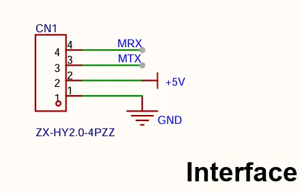
This module connects to the external main controller via CN1. CN1-1 is GND, CN1-2 is + 5V, CN1-3 is MTX, and CN1-4 is MRX. The + 5V power supply is regulated to 3.3V via the onboard AMS1117-3.3V to power the E103-W02; the UART of the external main controller must use 3.3V logic level.
CN1 Pin | network | Connection Instructions |
1 | GND | Connect the main controller to the power ground |
2 | +5V | Module Baseboard Power Input |
3 | MTX | Connect to MCU_TX; UART input of the module |
4 | MRX | Connect to MCU_RX; output from the module UART |
SW2 is the hardware reset button. SW1 is the factory reset button: hold down SW1 when powering on, then press SW2 once to reset, and wait for the three status indicator lights to flash alternately three times to complete the factory reset.
LED1 serves as the + 5V power indicator; LED2 corresponds to GPIO9 and remains steadily on when Wi-Fi connection is established successfully; LED3 corresponds to GPIO10 and stays illuminated when the network link is set up; LED4 corresponds to GPIO11 and keeps lit when entering the SmartConfig state.
3.3 Application Experiment
Taking the USB-to-TTL serial port module or a main controller with UART as an example below, this section conducts basic verification on the AT communication, AP mode and STA mode of the E103-W02. Before testing, confirm that the serial port level is 3.3V, and the default parameters are set to 115200bps, 8 data bits, no parity, and 1 stop bit.
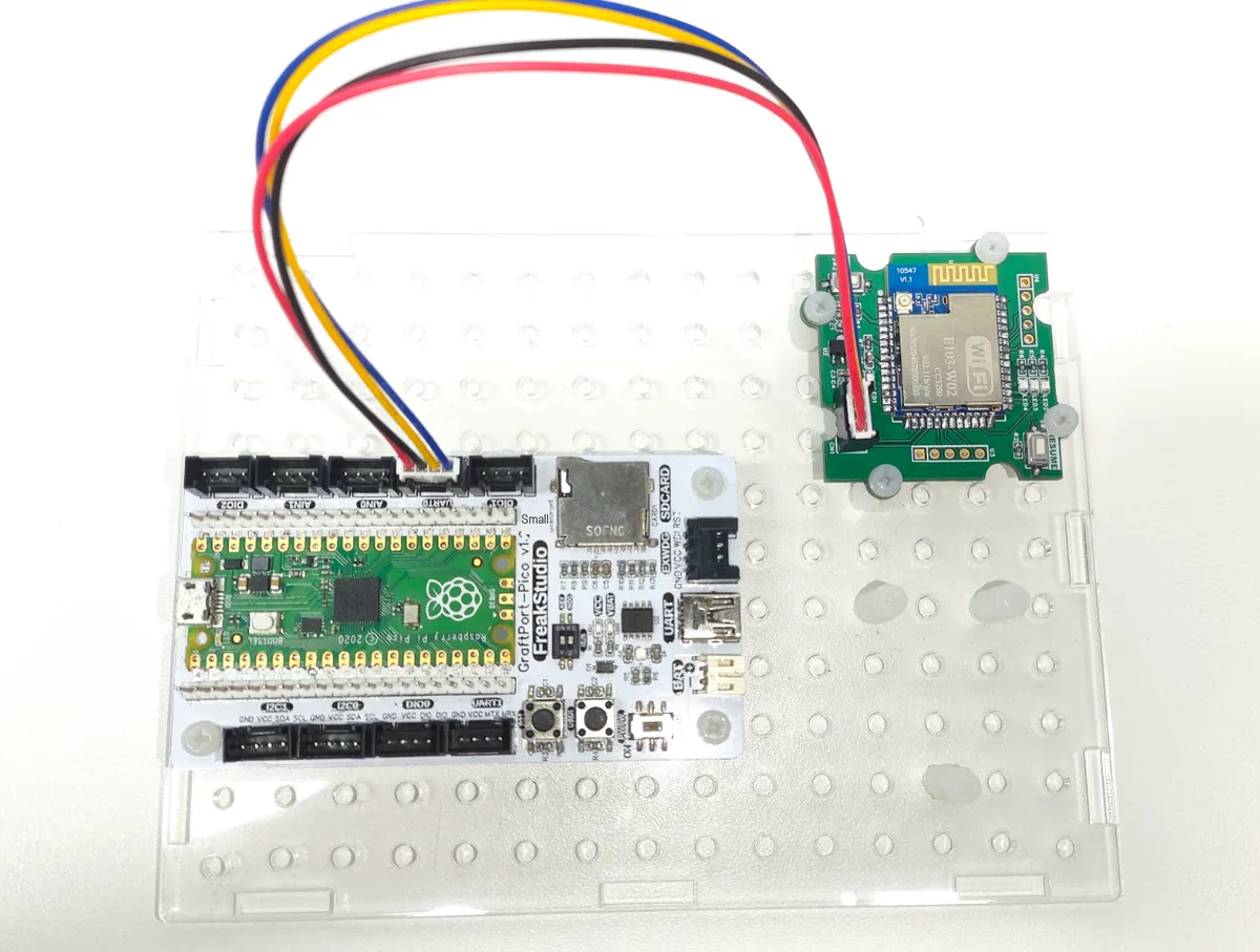
Here, we first use the HY2.0-4P connection cable to connect the module to the GraftPort-RP2040 development board's UART0 interface:
The module connections are shown in the following table:
Development Board Pins | Module Pins | Description |
Pin 16 |
|
|
Pin 17 |
|
|
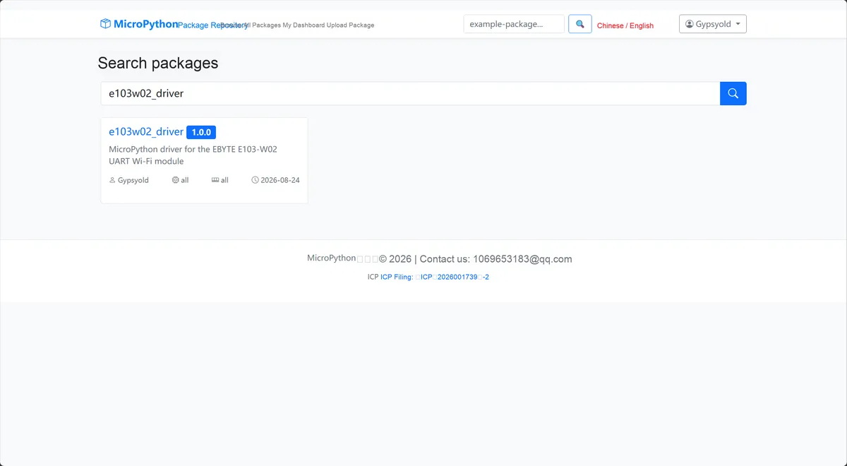
Here, we need to search for the relevant driver packages on uPyPI: https://upypi.net/zh/
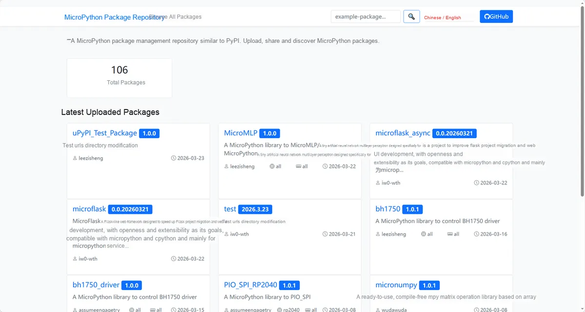
Enter e103w02_driver to search, and the following will be displayed:
Click to copy the local installation command:
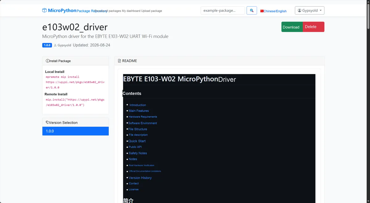
Here, we can import the module driver library code via the mip tool. The usage commands for the mpremote tool are as follows:
mpremote mip install https://upypi.net/pkgs/e103w02_driver/1.0.0After importing the driver code of EBYTE's E103-W02 Wi-Fi serial communication module, copy the following main.py code into our project:
# Python env   : MicroPython v1.23.0
# -*- coding: utf-8 -*-
# @Time    : 2026/8/20
# @Author  : FreakStudio
# @File    : main.py
# @Description : E103-W02 parameter query and AP TCP Server transparent transmission example, for Raspberry Pi Pico
# @License : MIT

__version__ = "1.0.0"
__author__ = "FreakStudio"
__license__ = "MIT"

# ======================================== Import Modules =========================================

# Import the time module, used for power-on delay and loop send interval
import time

# Import the pin and UART serial control classes from the machine module
from machine import Pin, UART

# Import the E103-W02 driver class
from e103w02 import E103W02

# ======================================== Global Variables ============================================

# UART0 configuration, matching the GP16/GP17 wiring of the current RP2040 project
UART_ID = 0
UART_BAUDRATE = 115200
UART_TX_PIN = 16
UART_RX_PIN = 17

# Transparent transmission test parameters
SEND_INTERVAL_SECONDS = 2
RECEIVE_TIMEOUT_MS = 1500

# All operations that modify module configuration or state are locked by default
RUN_CONFIGURATION_TESTS = False
RUN_UART_CONFIGURATION_TEST = False
RUN_RESET_TEST = False
RUN_FACTORY_RESTORE_TEST = False
RUN_RAW_COMMAND_TEST = False
RUN_READLINE_TEST = False

TEST_SSID = "YOUR_WIFI_SSID"
TEST_PASSWORD = "YOUR_WIFI_PASSWORD"
TEST_REMOTE_IP = "192.168.1.100"

# ======================================== Functions ============================================

# ======================================== Custom Classes ============================================

# ======================================== Initialization configuration ===========================================

# Delay 3 seconds to ensure the RP2040 and E103-W02 module finish power-on initialization
time.sleep(3)
print("FreakStudio: Initialize E103-W02 module and hardware")

# Carrier board interface naming is based on the main controller: GP16 connects to MTX, GP17 connects to MRX
uart = UART(
    UART_ID,
    baudrate=UART_BAUDRATE,
    bits=8,
    parity=None,
    stop=1,
    tx=Pin(UART_TX_PIN),
    rx=Pin(UART_RX_PIN),
    timeout=0,
)

# Create E103-W02 driver object; construction does not send AT commands
wifi = E103W02(uart)

# ========================================  Main Program  ============================================

try:
    # Use the official +++ escape sequence to enter AT mode from transparent transmission mode
    wifi.enter_command_mode()
    try:
        # Query basic module information
        print("[E103-W02 Version]: %s" % wifi.get_version())
        print("[E103-W02 Device SN]: %s" % wifi.get_device_sn())
        print("[E103-W02 MAC]: %s" % wifi.get_mac())
        print("[E103-W02 All State]: %s" % wifi.get_all_state())

        # Query current Wi-Fi and network configuration without modifying the module's persistent parameters
        print("[E103-W02 Status]: %s" % wifi.get_status())
        print("[E103-W02 Role]: %s" % wifi.get_role())
        print("[E103-W02 STA]: %s" % wifi.get_sta())
        print("[E103-W02 STA IP]: %s" % wifi.get_sta_ip())
        print("[E103-W02 AP]: %s" % wifi.get_ap())
        print("[E103-W02 AP IP]: %s" % wifi.get_ap_ip())
        print("[E103-W02 AP Channel]: %s" % wifi.get_ap_channel())
        print("[E103-W02 Run Mode]: %s" % wifi.get_mode())
        print("[E103-W02 Socket]: %s" % wifi.get_socket())
        print("[E103-W02 UART]: %s" % wifi.get_uart_config())
        print("[E103-W02 Driver AT Mode]: %s" % wifi.is_command_mode())

        if RUN_RAW_COMMAND_TEST:
            print("[E103-W02 Raw]: %s" % wifi.send_command("AT+VER=?"))

        if RUN_CONFIGURATION_TESTS:
            if TEST_SSID == "YOUR_WIFI_SSID" or TEST_PASSWORD == "YOUR_WIFI_PASSWORD":
                raise ValueError("replace configuration placeholders before unlocking tests")
            print(wifi.set_role(E103W02.ROLE_STA))
            print(wifi.set_mode(E103W02.MODE_NORMAL))
            print(wifi.set_sta(TEST_SSID, E103W02.SECURITY_WPA2, TEST_PASSWORD))
            print(wifi.set_sta_ip(E103W02.IP_MODE_DHCP, "192.168.1.200", "255.255.255.0", "192.168.1.1", "192.168.1.1"))
            print(wifi.set_ap("E103_W02_TEST", E103W02.SECURITY_WPA2, "change_me_123"))
            print(wifi.set_ap_ip("192.168.1.1", "255.255.255.0", "192.168.1.1", "192.168.1.1"))
            print(wifi.set_ap_channel(11))
            print(wifi.set_socket(E103W02.PROTOCOL_TCP, E103W02.SOCKET_CLIENT, TEST_REMOTE_IP, 8889, 8887))

        if RUN_UART_CONFIGURATION_TEST:
            print(wifi.set_uart_config(115200, 8, 0, 1))

        if RUN_FACTORY_RESTORE_TEST:
            print(wifi.restore_factory_defaults(confirm=True))

        if RUN_RESET_TEST:
            print(wifi.reset(confirm=True))
    finally:
        # Exit AT mode after the query, restoring transparent transmission between UART and network
        if wifi.is_command_mode():
            wifi.exit_command_mode()

    print("\nConnect the PC to the AP, then connect a TCP client to 192.168.1.1:8887")

    # Initialize message counter, used to distinguish the data of each transparent transmission
    count = 1

    # Continuously run the bidirectional transparent transmission test, UART to TCP and TCP to UART
    while True:
        # Build a test message with a counter and newline
        message = "E103-W02 message %d\r\n" % count

        # Pass the test message via UART to the E103-W02 for transparent transmission to the TCP client
        wifi.write(message)
        print("\n[Transparent TX]: %s" % message.strip())

        # Wait within the time limit for the PC to echo the data back unchanged
        response = wifi.read(timeout_ms=RECEIVE_TIMEOUT_MS)
        if response:
            print("[Transparent RX]: %s" % response)
        else:
            print("[Transparent RX]: No data (check PC Wi-Fi and TCP client)")

        if RUN_READLINE_TEST:
            print("[Transparent Line]: %s" % wifi.readline(timeout_ms=RECEIVE_TIMEOUT_MS))

        # Update the counter and wait for the next send
        count += 1
        time.sleep(SEND_INTERVAL_SECONDS)
except KeyboardInterrupt:
    print("\nE103-W02 example stopped by user")
except OSError as exc:
    print("E103-W02 hardware error: %s" % exc)
except Exception as exc:
    print("E103-W02 example failed: %s" % exc)
finally:
    # The driver does not own the external UART object, only cleans up internal mode state
    wifi.deinit()
    del wifi
    del uart
    print("E103-W02 example finished")
To flash the code, open a terminal and use the mpremote tool to connect to the main controller, then run main.py
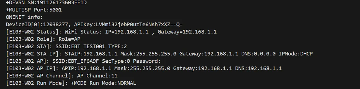
| Item | Information |
|---|---|
| Firmware version | 7152-0-36 |
| Device serial number | 191126173603FF1D |
| MAC address | 3CE064EF6A9F |
| Working role | AP |
| AP SSID | EBT_EF6A9F |
| AP channel | 11 |
| AP IP | 192.168.1.1 |
| Subnet mask | 255.255.255.0 |
| Gateway | 192.168.1.1 |
| Operating mode | NORMAL |
| Communication protocol | TCP Server |
| Local port | 8887 |
| Remote port | 8889 |
| UART parameters | 115200bps, 8 data bits, no parity, 1 stop bit |
| Drive AT mode | TRUE |
We need to install the TCP&UDP debugger, and the following will briefly demonstrate its basic functions.
SocketTool4.zip 1.5 MB
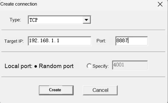
- Open the debugging tool, select Client connection, and create a new connection method
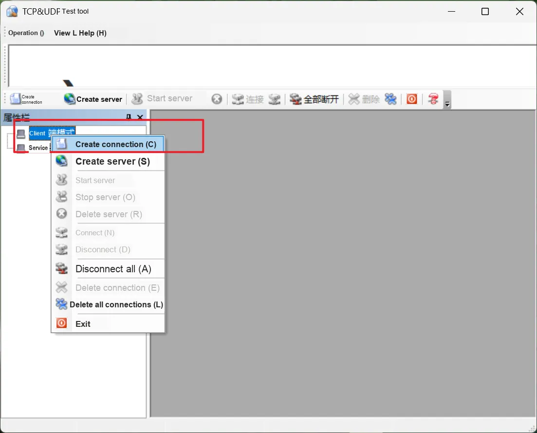
- Fill in the corresponding target IP and Port Number according to the information in the above table
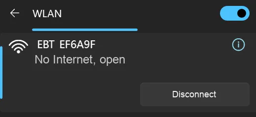
- Then connect to the Wi-Fi of the module

- Run the test program
Test program demo.mp4 31.0 MB
4. Drivers
e103w02_driver.zip 21 KB
5. BOM & Recommended Alternative Parts
To obtain BOM and recommended alternative parts, please follow our official account [Freak Embedded]
VI. Revision History
Document Version | Date of Revision | Modifier | Modify Content |
v1.0 | 2026-8-20 | Mi Ming Xuan | Initialize the document |
v1.1 | 2026-8-26 | Mi Ming Xuan | The circuit section has not been added yet. |
VII. Relevant Materials
Refer to the technical parameters, pins, AT commands and circuit descriptions of E103, which are subject to the local official manual and schematic diagram.
E103-W02_Datasheet_CN_V3.3.pdf 3.6 MB
E103.pdf 498 KB