Contents
- I. Module Introduction
- II. Introduction to Main Chips
- 2.1 Chip Overview
- 2.2 Pin Definition
- 2.3 Functional Block Diagram
- 2.4 Performance Parameters
- 2.5 Reference Circuit
- 2.6 Chip Configuration
- 2.7 Communication Interfaces and Related Protocols
- 2.8 PCB Routing Notes
- III. Circuit Engineering
- 3.1 Circuit Source Engineering
- 3.2 Module Usage Instructions
- 3.3 Application Experiment
- IV. Drivers
- 5. BOM & Recommended Alternative Parts
- 6. Revision History
- VII. Relevant Materials
- 7.1 Chip Datasheet
- 7.2 Unique Icons for PCB Silk Screen
I. Module Introduction
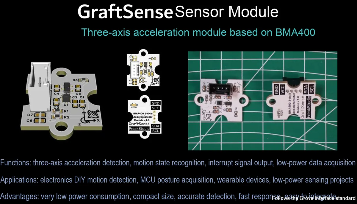
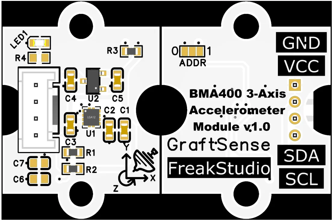
Tri-axis acceleration module based on BMA400, adopts the BMA400 chip solution. It is a 12-bit digital tri-axis Acceleration Sensor that supports four programmable measurement ranges of ±2g/±4g/±8g/±16g, with a maximum output data rate up to 800Hz. It has a built-in 1KB FIFO buffer and on-chip interrupt functions including step counting, activity recognition, and automatic wake-up. The current in low-power mode is only 3.5μA. The module integrates LDO voltage regulation, power filtering, and I²C pull-up circuits. The device address is configured via the ADDR pin, and it is compatible with 3.3V level MCUs, making it suitable for low-power inertial sensing scenarios such as motion detection, vibration monitoring, wearable devices, and smart homes.
II. Introduction to Main Chips
BMA400 is a 12-bit 3-axis digital Acceleration Sensor that supports programmable measurement ranges from ±2g to ±16g, offers a maximum output data rate of 800Hz, integrates a built-in 1KB FIFO and interrupt functions such as step counting and activity recognition, draws only 3.5μA in low-power mode, and is suitable for low-power motion and vibration detection scenarios.
2.1 Chip Overview
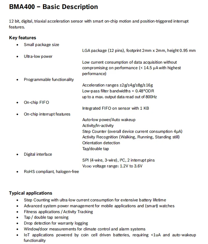
BMA400 is a 12-bit digital tri-axis Acceleration Sensor that adopts a 2×2mm LGA-12 package, featuring ultra-low power consumption (current < 14.5μA in maximum performance mode, only 4μA in step counting mode), programmable measurement range(±2g~±16g), maximum output data rate of 800Hz, 1KB on-chip FIFO and rich on-chip interrupt functions (auto-wakeup, step counting, activity recognition, tap detection, etc.), supporting SPI / I²C digital interfaces, with a VDDIO voltage range of 1.2~3.6V, complying with RoHS halogen-free standards, and is suitable for low-power motion detection scenarios such as step counting, wearables, and IoT.
2.2 Pin Definition
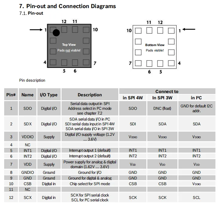
The BMA400 chip adopts a 12-pin LGA package, with top and bottom views provided; its pins include SPI / I²C multiplexed interfaces (SDO / SDX / SCX / CSB), power supply pins (VDDIO / VDD), ground pins (GNDIO / GND), two interrupt outputs (INT1 / INT2) and two NC pins. The functions and connection modes of each pin vary under different communication modes (SPI 4W / SPI 3W / I²C); in the I²C mode, the SDO pin can be used for address selection.
2.3 Functional Block Diagram
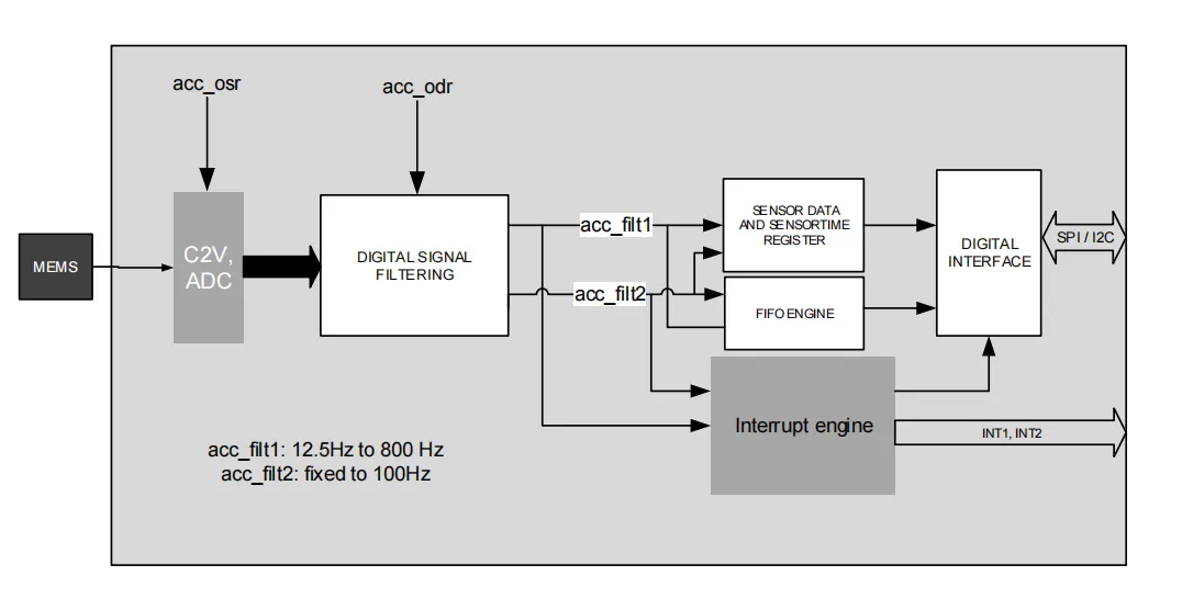
The signal processing flow of BMA400 is as follows: The capacitive signal output by the MEMS sensing element is converted via C2V and sampled by ADC, then processed by the digital signal filtering module to generate two channels of filtered data (acc_filt1: adjustable bandwidth from 12.5Hz to 800Hz, acc_filt2: fixed 100Hz bandwidth). The filtered data can be sent to the sensor data register or buffered by the 1KB FIFO engine; meanwhile, the interrupt engine triggers an interrupt via INT1 / INT2 according to the data, and finally outputs acceleration data externally through the SPI / I²C digital interface. Among them, acc_osr and acc_odr are respectively used to configure the oversampling ratio and output data rate to balance noise and power consumption.
2.4 Performance Parameters
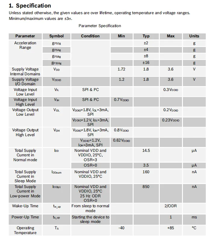
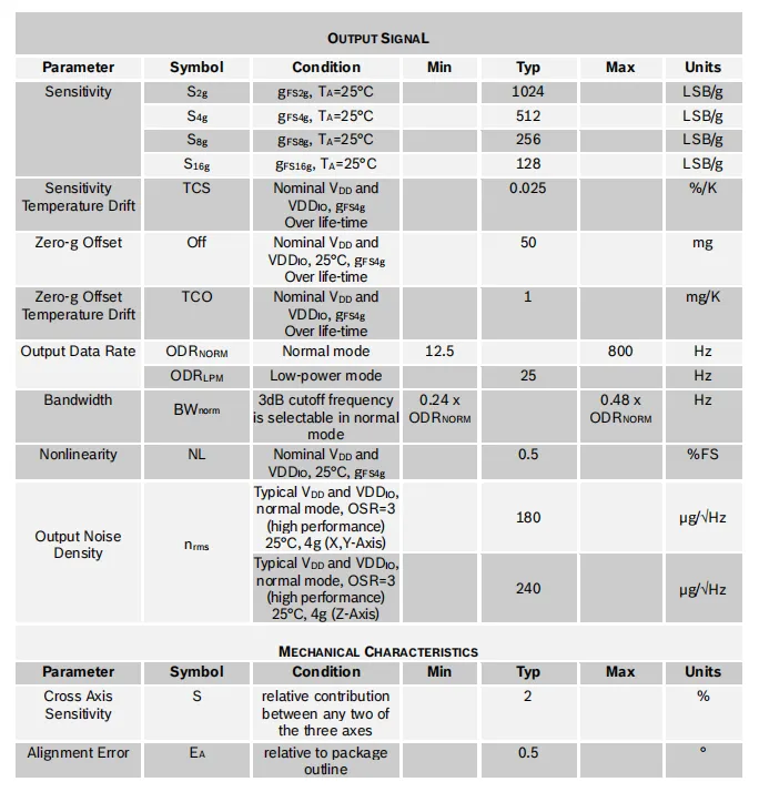
BMA400 supports programmable measurement ranges of ±2g/±4g/±8g/±16g, with internal and IO supply voltages of 1.72~3.6V and 1.2~3.6V respectively; it features a typical current consumption of 14.5μA in normal mode, merely 160nA in suspend mode, and 850nA in low-power mode.In terms of output signals, the sensitivity decreases with the measurement range (1024~128 LSB/g), the output data rate is 12.5~800Hz in normal mode and up to 25Hz in low-power mode, with a nonlinearity of 0.5% FS, output noise density of 180~240μg/√Hz; in terms of mechanical properties, the cross-axis sensitivity is 2%, alignment error is 0.5°, and operating temperature ranges from -40 to + 85°C.
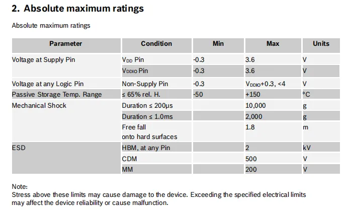
BMA400 has VDD and VDDIO power supply pins with a withstand voltage range of -0.3V to 3.6V; the withstand voltage of logic pins shall not exceed VDDIO + 0.3V with an upper limit of 4V; the storage temperature ranges from -50℃ to + 150℃(humidity ≤ 65% RH); it can withstand mechanical shocks of 10000g within 200μs, 2000g within 1ms, and a free fall from 1.8m;ESD protection ratings are HBM 2kV, CDM 500V, MM 200V. Exceeding these limits may damage the device or impair its reliability.
2.5 Reference Circuit
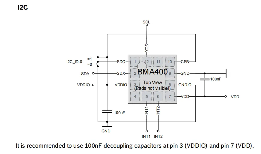
The BMA400 chip uses an I²C interface, where the SCX pin is connected to the SCL clock, the SDX pin is connected to the SDA data line, the CSB pin is connected to VDDIO to select the I²C mode, and the SDO pin is used to configure the I²C address;VDD and VDDIO pins are each connected to a 100nF decoupling capacitor to GND; the GND and GNDIO pins share a common ground. The INT1 / INT2 pins are reserved as interrupt outputs, and it is recommended to add a 100nF decoupling capacitor to the VDD and VDDIO power supply pins to ensure stability.
2.6 Chip Configuration
None.
2.7 Communication Interfaces and Related Protocols
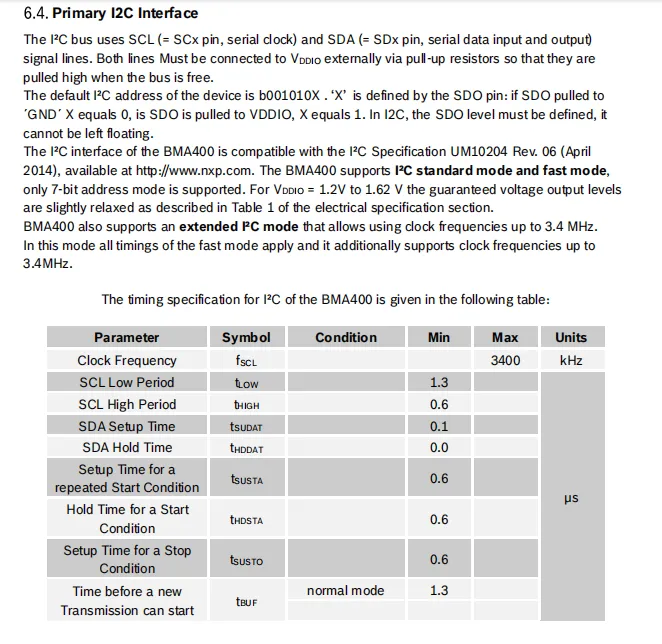
BMA400 's I ² C interface uses SCX ( SCL ) and SDX ( SDA ) signals, and requires an external pull-up resistor to VDDIO ; the default slave address is b001010X , X is determined by the SDO pin level (ground is 0, connected to VDDIO is 1), and the SDO level must be clear; the interface is compatible with I ² C standard/fast mode, supports up to 3.4MHz extended I ² C mode, and gives specific timing Parameters (such as clock frequency up to 3.4MHz, SCL low level ≥ 1.3μs, etc.).
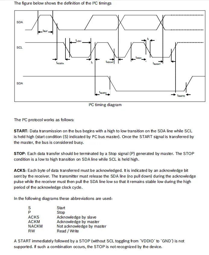
BMA400 I²C Timing and Protocol Description: START is defined as the high-level period when high-level period when SDA transitions from high to low;STOP is defined as the SCL high-level period when SDA transitions from low to high; after each byte transmission, the receiver shall pull SDA low for acknowledgment, and the transmitter shall release the SDA line; the Sequence Diagram marks the key parameters, and it is also specified that the invalid combination of " START followed immediately by STOP " is not supported, otherwise the STOP signal will not be recognized.
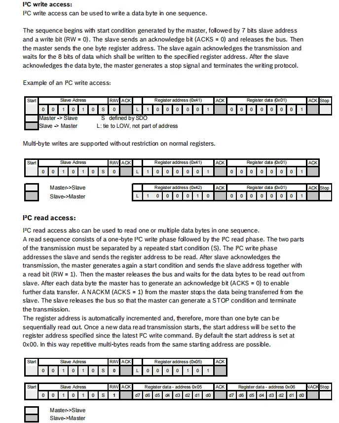
BMA400 I²C single-byte read/write and multi-byte write process is: Start → Slave Address + Write Bit → Register Address → Data Byte → Stop, with slave acknowledgment at each stage; for read operations, the register address must first be written via the phase, then the Start → Slave Address + Read Bit sequence is repeated, after which the slave automatically increments the address and returns multi-byte data, with the master acknowledging each byte (sending a non-acknowledgment for the last byte), and the default start address is 0x00.
2.8 PCB Routing Notes
None.
III. Circuit Engineering
3.1 Circuit Source Engineering
To obtain the circuit source project, please follow the official account [Freak Embedded].
3.2 Module Usage Instructions
The schematic diagram of this module is shown below:
SCH_3-Axis Accelerometer Module Based on BMA400-V1.0.0_2026-03-27.pdf 2.3 MB
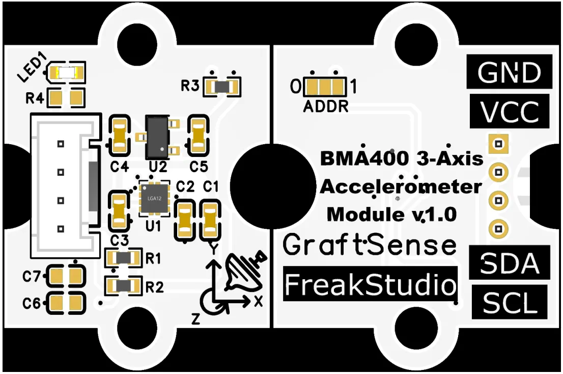
This module provides an I²C communication interface: it supports standard and fast-mode I²C communication with a maximum scalable communication rate of 3.4MHz; the device address can be flexibly configured via the ADDR pin to avoid bus conflicts, and it is compatible with 3.3V-level MCUs. It enables reading and writing of three-axis acceleration data with a programmable measurement range of ±2g to ±16g, integrates a built-in 1KB FIFO and on-chip interrupt functions including step counting and activity recognition, and features a current consumption of only 3.5μA in low-power mode. It is suitable for low-power inertial sensing scenarios such as motion detection, vibration monitoring, wearable devices and smart homes, and provides stable and efficient inertial data interaction capabilities for the system.
3.3 Application Experiment
Here, we use the GraftPort-RP2040 development board for testing, and the BMA400-based three-axis acceleration module uses the I2C interface to communicate with the main controller.
Here, we first use the HY2.0-4P connection cable to connect the module to the GraftPort-RP2040 development board's I2C0 interface:
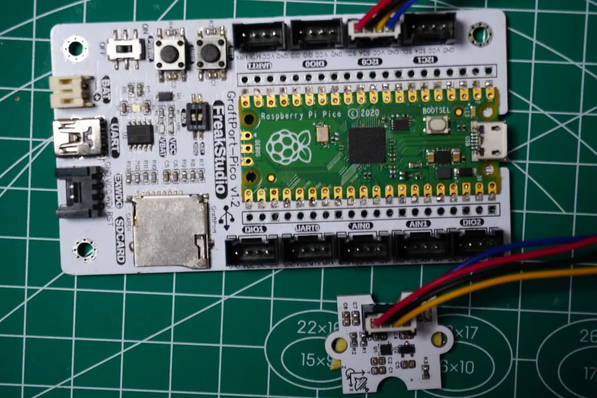
The module connections are shown in the following table:
Development Board Pins | Module Pins | Description |
Pin 4 |
|
|
Pin 5 |
|
|
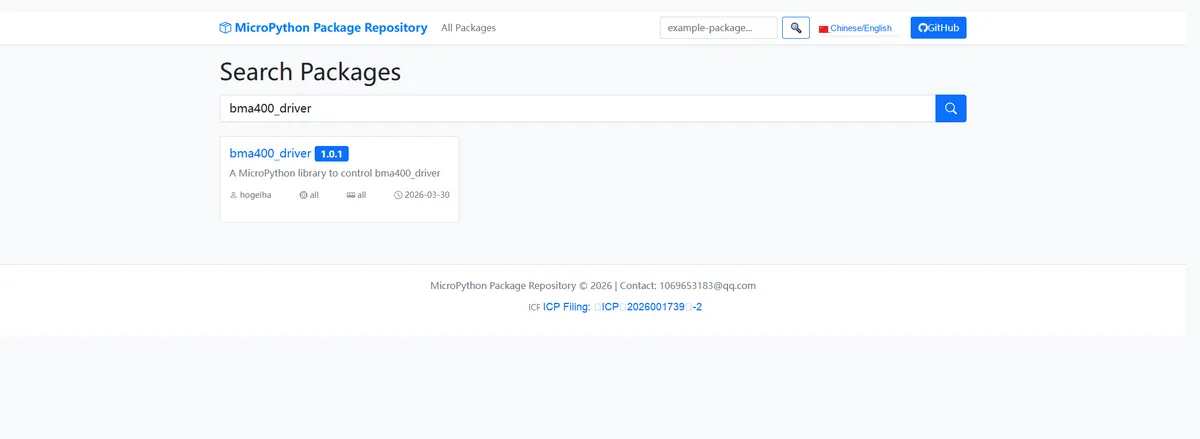
Here, we need to search for the relevant driver packages on uPyPI: https://upypi.net/zh/
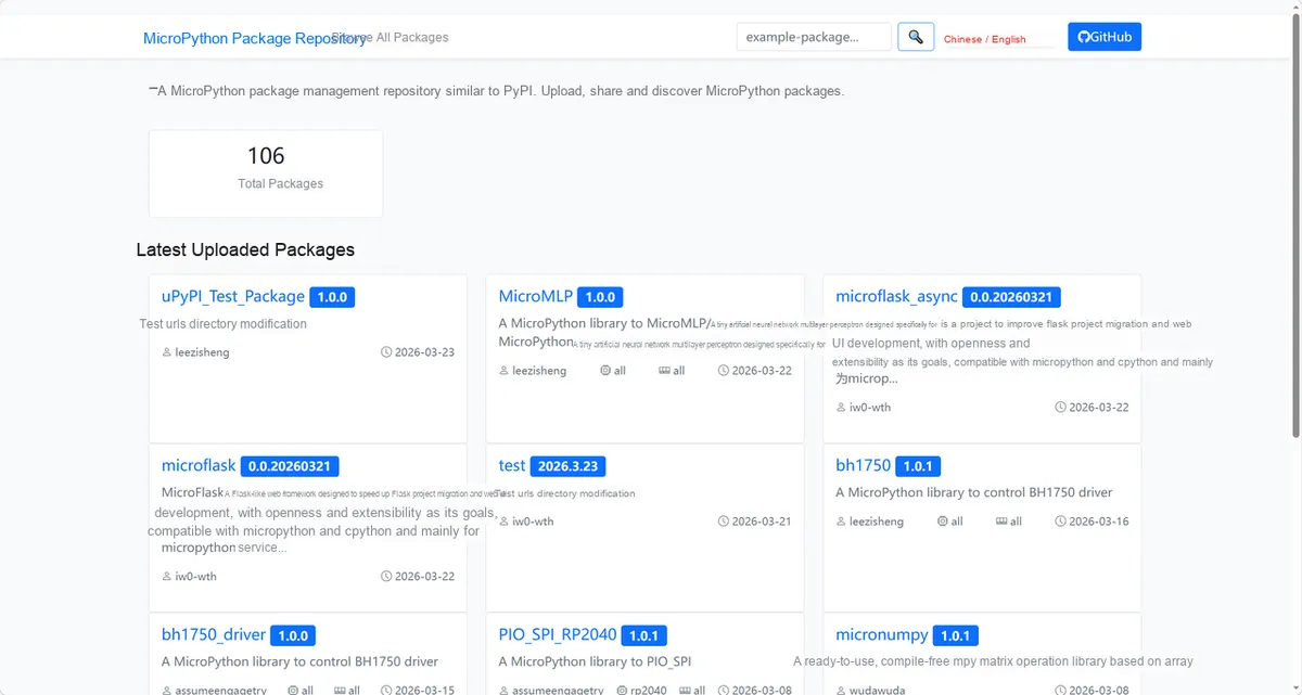
Enter bma400_driver to search, and the following will be displayed:
Click to copy the local installation command:
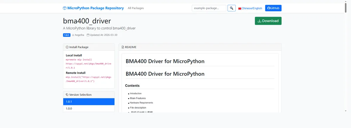
Import the module driver library code via the mip tool. Below are the usage commands for the mpremote tool:
mpremote mip install https://upypi.net/pkgs/bma400_driver/1.0.0Import the MicroPython driver code for the BMA400-based 3-axis acceleration module, then copy the following main.py code into our project:
# Python env   : MicroPython v1.23.0
# -*- coding: utf-8 -*-
# @Time    : 2026/3/12 5:30 PM
# @Author  : hogeiha
# @File    : main.py
# Description : BMA400 sensor parameter configuration demo: configure power mode/data rate/filter/oversampling/range, read acceleration and temperature

# ======================================== Import Modules =========================================

import time
from machine import Pin, I2C
from bma400 import BMA400

# ======================================== Global Variables ============================================

# I2C hardware configuration
I2C_SDA_PIN = 4
I2C_SCL_PIN = 5
I2C_FREQ = 400000

# Automatically identify the sensor address, define a global target address list (supports multiple addresses; use [] even for a single one)
TARGET_BMA400_ADDRS = [0x14,0x15]

# ======================================== Functions ============================================


def print_separator(title):
    """Print separator for better readability"""
    print("\n" + "=" * 60)
    print(f"=== {title}")
    print("=" * 60)


def read_sensor_data(bma):
    """Safely read sensor data with exception handling"""
    try:
        accx, accy, accz = bma.acceleration
        temp = bma.temperature
        return (accx, accy, accz), temp
    except OSError as e:
        if "EIO" in str(e):
            print(f"  ERROR: I2C communication error (Errno 5): {e}, retrying...")
        else:
            print(f"  ERROR: Failed to read data: {e}")
        return None, None
    except Exception as e:
        print(f"  ERROR: Unknown error: {e}")
        return None, None


def set_sensor_param(bma, param_name, value, valid_values):
    """Safely set sensor parameters with exception handling"""
    try:
        if value not in valid_values:
            print(f"  WARNING: Invalid value {value}, skipping")
            return False

        setattr(bma, param_name, value)
        current_value = getattr(bma, param_name)
        print(f"  SUCCESS: Parameter set - Current {param_name}: {current_value} (Target value: {value})")
        return True
    except OSError as e:
        if "EIO" in str(e):
            print(f"  ERROR: I2C communication error (Errno 5) when setting {param_name}: {e}")
        else:
            print(f"  ERROR: Failed to set {param_name}: {e}")
        return False
    except ValueError as e:
        print(f"  WARNING: Invalid value for {param_name}: {e}")
        return False
    except Exception as e:
        print(f"  ERROR: Unknown error when setting {param_name}: {e}")
        return False


# ======================================== Custom Classes ============================================

# ======================================== Initialization configuration ===========================================

time.sleep(3)
print("FreakStudio: BMA400 Sensor Parameter Configuration and Data Reading Demonstration")

# I2C initialization (compatible with I2C/SoftI2C)
i2c_bus = I2C(0, sda=Pin(I2C_SDA_PIN), scl=Pin(I2C_SCL_PIN), freq=I2C_FREQ)

# Start scanning for devices on the I2C bus
devices_list: list[int] = i2c_bus.scan()
print("START I2C SCANNER")

# Check the I2C device scan result
if len(devices_list) == 0:
    print("No i2c device !")
    raise SystemExit("I2C scan found no devices, program exited")
else:
    print("i2c devices found:", len(devices_list))

# Iterate over the address list to initialize the target sensor
sensor = None  # Placeholder for the sensor object initialization
for device in devices_list:
    if device in TARGET_BMA400_ADDRS:
        print("I2c hexadecimal address:", hex(device))
        try:
            # Automatically identify and initialize the corresponding sensor
            sensor = BMA400(i2c=i2c_bus ,address=device)
            print("Sensor initialization successful")
            break
        except Exception as e:
            print(f"Sensor Initialization failed: {e}")
            continue
else:
    # Target device not found, raise an exception
    raise Exception("No target sensor device found in I2C bus")

# ========================================  Main Program  ============================================

# 1. Power mode configuration demo
print_separator("1. Power Mode Configuration Demo")
for power_mode in BMA400.power_mode_values:
    if power_mode == BMA400.SWITCH_TO_SLEEP:
        continue
    if set_sensor_param(sensor, "power_mode", power_mode, BMA400.power_mode_values):
        acc_data, temp = read_sensor_data(sensor)
        if acc_data and temp is not None:
            accx, accy, accz = acc_data
            print(f"    Acceleration: x={accx:.2f} m/s², y={accy:.2f} m/s², z={accz:.2f} m/s²")
            print(f"    Temperature: {temp:.2f} °C")
    time.sleep(1)

# Restore normal mode

set_sensor_param(sensor, "power_mode", BMA400.NORMAL_MODE, BMA400.power_mode_values)

# 2. Output data rate configuration demo
print_separator("2. Output Data Rate Configuration Demo")
for odr in BMA400.output_data_rate_values:
    set_sensor_param(sensor, "output_data_rate", odr, BMA400.output_data_rate_values)
    time.sleep(0.5)

# 3. Filter bandwidth configuration demo
print_separator("3. Filter Bandwidth Configuration Demo")
for bw in BMA400.filter_bandwidth_values:
    if set_sensor_param(sensor, "filter_bandwidth", bw, BMA400.filter_bandwidth_values):
        print("    Continuous 3 acceleration readings:")
        for _ in range(3):
            acc_data, _ = read_sensor_data(sensor)
            if acc_data:
                accx, accy, accz = acc_data
                print(f"      x={accx:.2f}, y={accy:.2f}, z={accz:.2f} m/s²")
            time.sleep(0.2)

# 4. Oversampling rate configuration demo
print_separator("4. Oversampling Rate Configuration Demo")
for osr in BMA400.oversampling_rate_values:
    if set_sensor_param(sensor, "oversampling_rate", osr, BMA400.oversampling_rate_values):
        acc_data, _ = read_sensor_data(sensor)
        if acc_data:
            accx, accy, accz = acc_data
            print(f"    Acceleration: x={accx:.2f}, y={accy:.2f}, z={accz:.2f} m/s²")
    time.sleep(0.5)

# 5. Acceleration range configuration demo
print_separator("5. Acceleration Range Configuration Demo")
for acc_range in BMA400.acc_range_values:
    if set_sensor_param(sensor, "acc_range", acc_range, BMA400.acc_range_values):
        acc_data, _ = read_sensor_data(sensor)
        if acc_data:
            accx, accy, accz = acc_data
            print(f"    Acceleration: x={accx:.2f}, y={accy:.2f}, z={accz:.2f} m/s²")
    time.sleep(0.5)

# 6. Source data register configuration demo
print_separator("6. Source Data Register Configuration Demo")
for src in BMA400.source_data_registers_values:
    if set_sensor_param(sensor, "source_data_registers", src, BMA400.source_data_registers_values):
        acc_data, _ = read_sensor_data(sensor)
        if acc_data:
            accx, accy, accz = acc_data
            print(f"    Acceleration: x={accx:.2f}, y={accy:.2f}, z={accz:.2f} m/s²")
    time.sleep(0.5)

# 7. Final sensor status summary
print_separator("7. Sensor Final Configuration Summary")
try:
    print(f"Power Mode: {sensor.power_mode}")
    print(f"Output Data Rate: {sensor.output_data_rate}")
    print(f"Filter Bandwidth: {sensor.filter_bandwidth}")
    print(f"Oversampling Rate: {sensor.oversampling_rate}")
    print(f"Acceleration Range: {sensor.acc_range}")
    print(f"Source Data Register: {sensor.source_data_registers}")

    acc_data, temp = read_sensor_data(sensor)
    if acc_data and temp is not None:
        accx, accy, accz = acc_data
        print(f"Current Acceleration: x={accx:.2f}, y={accy:.2f}, z={accz:.2f} m/s²")
        print(f"Current Temperature: {temp:.2f} °C")
except Exception as e:
    print(f"Failed to read final configuration: {e}")

print("\n=== Demo Completed ===")
Burn the code, open the terminal, and the output is as follows:
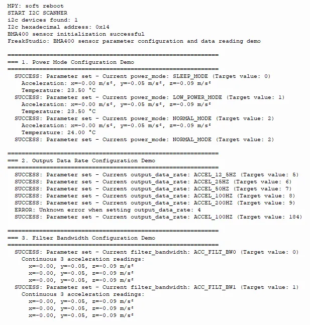
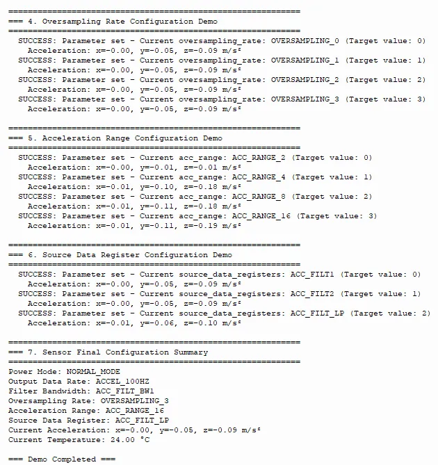
It can be seen that parameters can be configured sequentially, and acceleration and temperature data can be printed out.
IV. Drivers
bma400_driver-1.0.1.zip 16 KB
5. BOM & Recommended Alternative Parts
None.
6. Revision History
Document Version | Date of Revision | Modifier | Modified Content |
v1.0 | 2026-03-27 | Ling Gaoxing | Initialize the document |
v1.0.1 | 2026-04-05 | Li Zisheng | The homepage photo has not been taken, the production files have not been exported yet, and all other items have been sorted out completely. |
v1.0.2 | 2026-04-21 | Li Zisheng | The production documents have not been exported yet, while all the others have been sorted out completely. |
v1.1 | 2026-04-23 | Xin Ruili | Create an open version of the document, based on the internal document version v1.0.2. |
VII. Relevant Materials
7.1 Chip Datasheet
BMA400.pdf 7.3 MB
7.2 Unique Icons for PCB Silk Screen