Contents
- I. Module Introduction
- II. Introduction to Main Chips
- 2.1 Chip Overview
- 2.2 Pin Definition
- 2.3 Functional Block Diagram
- 2.4 Performance Parameters
- 2.5 Reference Circuit
- 2.6 Chip Configuration
- 2.7 Communication Interfaces and Related Protocols
- 2.8 PCB Routing Notes
- III. Circuit Engineering
- 3.1 Circuit Source Engineering
- 3.2 Module Usage Instructions
- 3.3 Application Experiment
- IV. Drivers
- 5. BOM & Recommended Alternative Parts
- 6. Revision History
- VII. Relevant Materials
- 7.1 Chip Datasheet
- 7.2 Unique Icons for PCB Silk Screen
I. Module Introduction
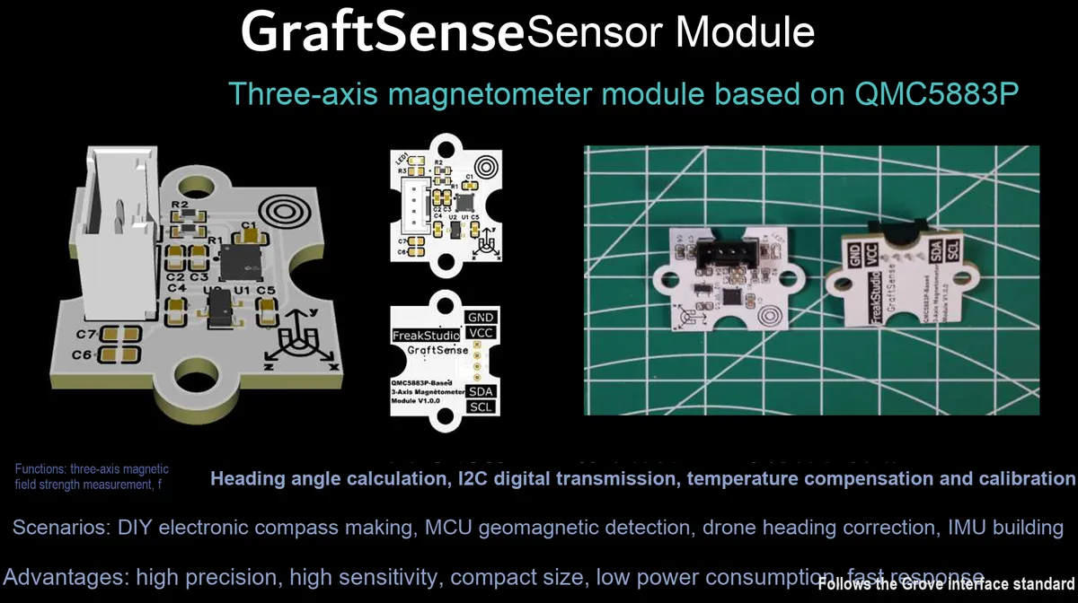
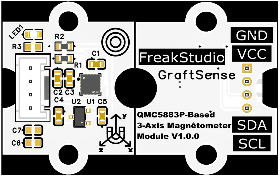
3-axis magnetometer module based on QMC5883P, which adopts the QMC5883P chip solution, is a 3-axis magnetoresistive sensor with a built-in 16-bit ADC and low-noise AMR sensor. It supports a magnetic field measurement range of ±2G to ±30G, offers a maximum output data rate of 1.5kHz, features offset elimination and temperature compensation functions, and can achieve a compass heading accuracy of 1°~2°;The module integrates LDO voltage regulation, power filtering and I²C pull-up circuits, is equipped with a power indicator, and is compatible with 3.3V level MCUs. It is suitable for magnetic field detection and positioning scenarios such as electronic compasses, map rotation, pedestrian navigation and wearable devices.
II. Introduction to Main Chips
QMC5883P is a 16-bit three-axis magnetoresistive sensor with a built-in 16-bit ADC and temperature compensation function. It supports magnetic field ranges from ±2G to ±30G, offers a maximum output data rate of 1.5kHz, and achieves a compass heading accuracy of 1°~2°, making it suitable for electronic compass and navigation and positioning scenarios.
2.1 Chip Overview
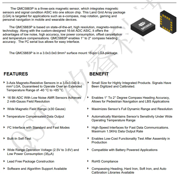
QMC5883P is a 3-axis magnetometer integrating a magnetoresistive sensor and signal conditioning ASIC, which adopts a 3.0×3.0×0.9mm 16-pin LGA package and operates at a temperature range of -40 to + 85℃;Built-in 16-bit ADC and low-noise AMR sensor, achieving a resolution of 2 milligauss, with a magnetic field range of ±30 gauss, and supporting temperature compensation and self-test functions;I²C interface with a maximum output data rate of 1.5kHz, operating at a supply voltage of 2.5~3.6V and consuming 35μA of power, capable of providing a compass heading accuracy of 1°~2°, suitable for applications such as electronic compasses and wearable navigation, and compliant with RoHS lead-free standards.
2.2 Pin Definition
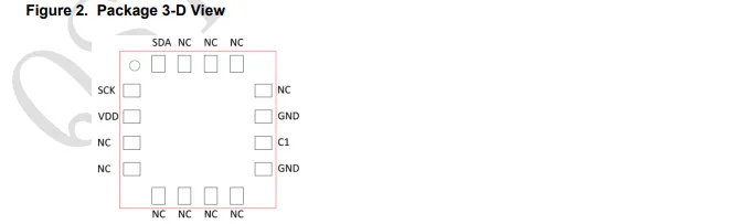
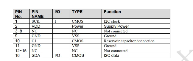
QMC5883P is a 16-pin LGA packaged chip that adopts a 3.0×3.0×0.9mm LGA package. Its valid pins only include the I²C clock (SCK), I²C data (SDA), power supply (VDD), dual ground pins (GND) and the energy storage capacitor connection terminal (C1); all other pins are NC (not connected). Among these pins, SCK functions as an input, SDA is a bidirectional I/O, and C1 is used to connect an energy storage capacitor.
2.3 Functional Block Diagram
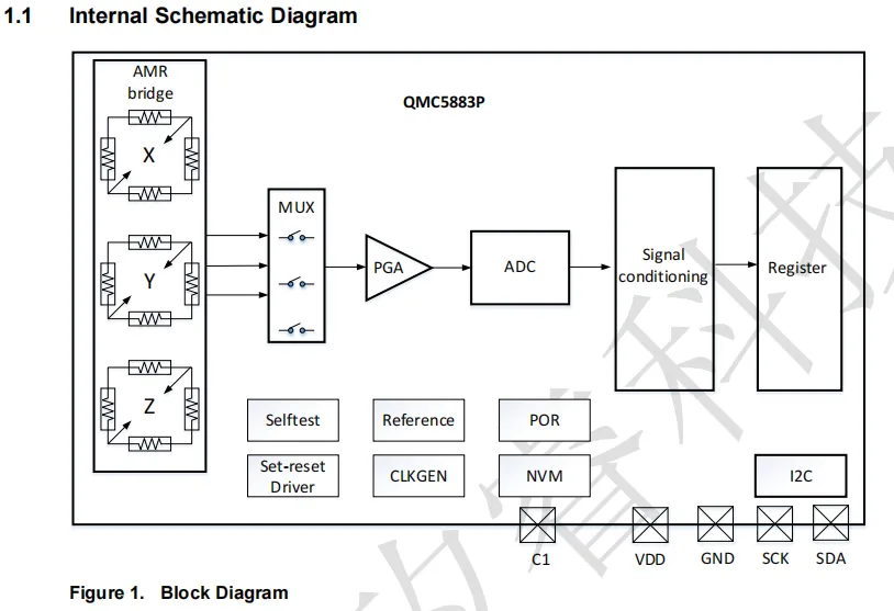
QMC5883P operates as follows: X / Y / Z three-axis AMR magnetoresistive bridges acquire magnetic field signals, which are selected by a multiplexer (MUX) and then sent to a programmable gain amplifier (PGA) for amplification, converted into digital values by a 16-bit ADC, and then processed by a signal conditioning module to complete offset elimination and temperature compensation; the results are stored in registers and output externally via the I²C interface.The chip also integrates auxiliary modules such as self-test, set-reset driver, clock generation, power-on reset (POR) and non-volatile memory (NVM), and cooperates with the energy storage capacitor terminal C1 and the power/communication pins to realize a stable magnetic field detection function.
2.4 Performance Parameters
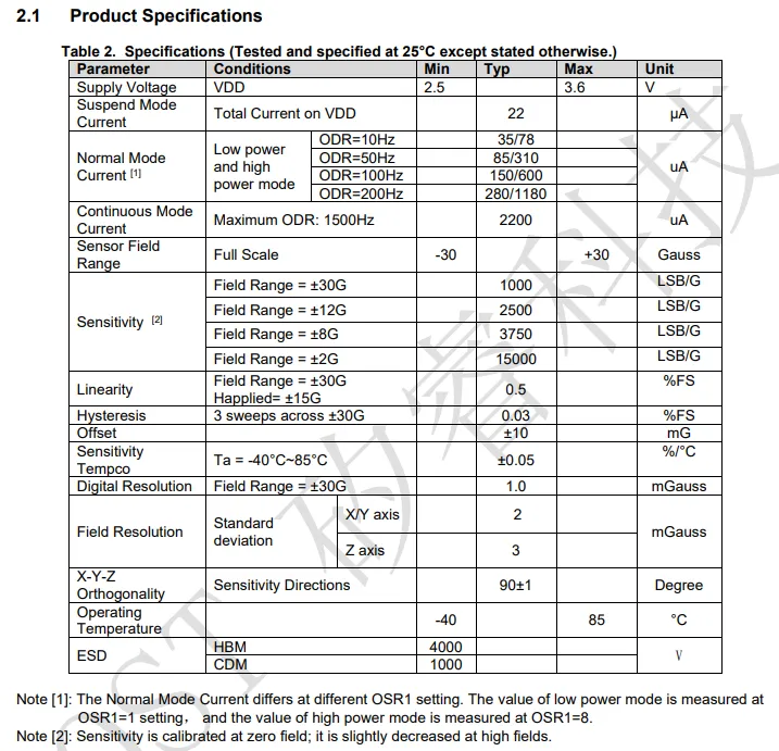
QMC5883P Power supply voltage: 2.5~3.6V, suspend mode typical current: 22μA; normal mode current varies with ODR and power consumption mode (35μA~1180μA corresponding to 10Hz~200Hz); in continuous mode, the maximum ODR is 1500Hz with a current of 2200μA;Magnetic field range: ±30 Gauss; sensitivity increases as the range decreases (15000 LSB/G at ±2G); linearity: 0.5% FS; digital resolution: 1 mGauss; field resolution: X / Y axis 2 mGauss, Z axis 3 mGauss; operating temperature: -40~85℃;ESD protection: HBM 4000V, CDM 1000V.
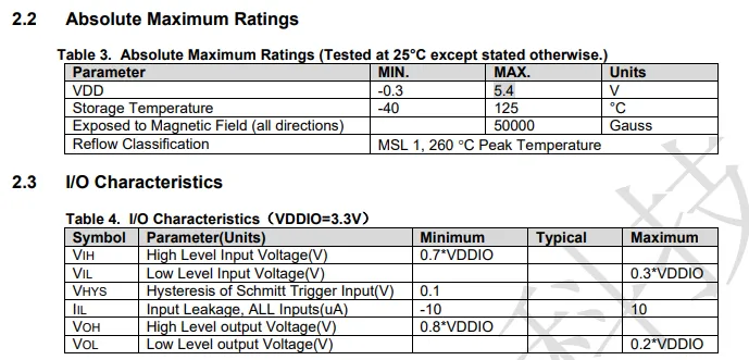
QMC5883P absolute maximum ratings include VDD withstand voltage of -0.3~5.4V, storage temperature of -40~125℃, withstand magnetic field of 50000 gauss, and the reflow soldering level is MSL 1 with a peak temperature of 260℃;I/O characteristics (VDDIO = 3.3V) specify that high-level input ≥0.7× VDDIO, low-level input ≤0.3× VDDIO, input leakage current ±10μA, high-level output ≥0.8× VDDIO, low-level output ≤0.2× VDDIO, and Schmitt trigger input hysteresis of 0.1V.
2.5 Reference Circuit
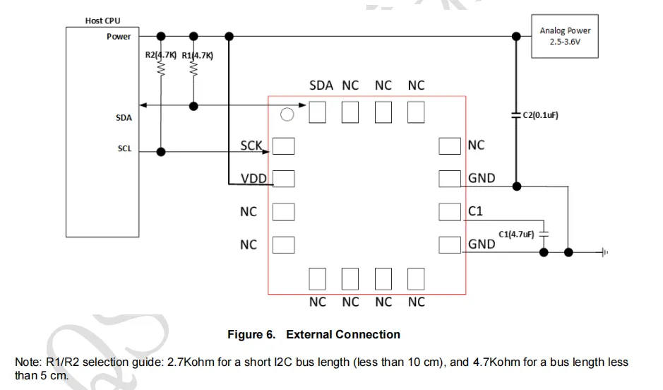
The QMC5883P chip communicates with the host CPU interface. A 4.7kΩ pull-up resistor (recommended for bus lengths <5cm) is connected to each of the I²C interface. A 4.7kΩ pull-up resistor (recommended for bus lengths <5cm) is connected to each of the SDA / SCL pins; the VDD pin is connected to a 2.5~3.6V analog power supply, with a 0.1μF decoupling capacitor connected in parallel to GND; the C1 pin is connected to a 4.7μF energy storage capacitor to GND, and the remaining NC pins are left floating. The document also notes the selection criteria for the I²C pull-up resistors (2.7kΩ is optional for bus lengths <10cm).
2.6 Chip Configuration
None.
2.7 Communication Interfaces and Related Protocols
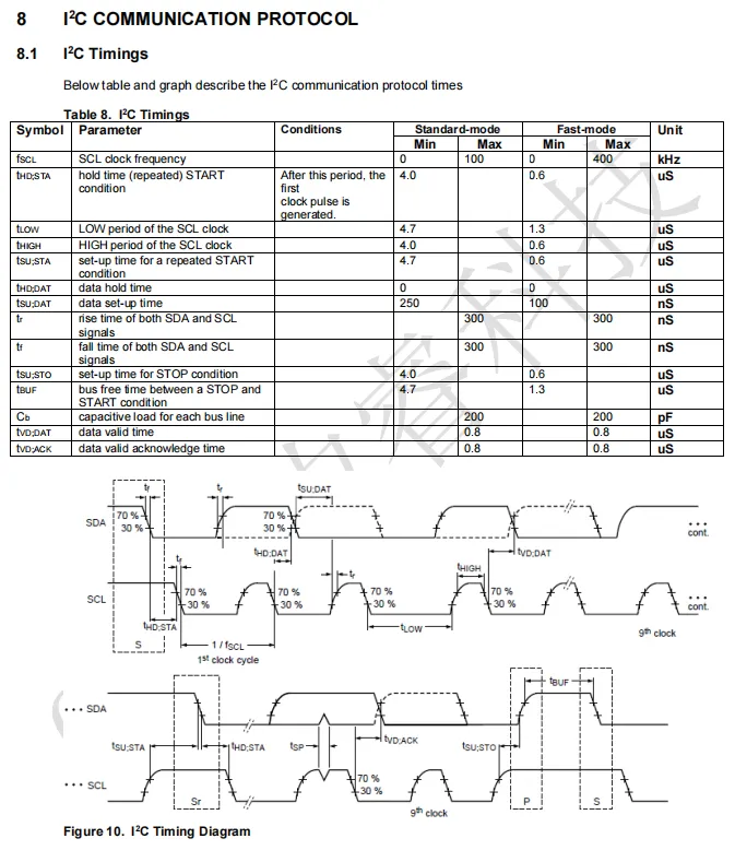
QMC5883P supports two clock frequencies for I²C communication: the standard mode (0~100kHz) and the fast mode (0~400kHz). The table specifies in detail parameters including the setup/hold time for START / STOP conditions, the high and low level periods of SCL, data setup/hold time, signal rise/fall time, etc. The waveform diagram visually illustrates the timing relationship between SDA and SCL in phases such as start, data transmission, acknowledge, and stop, and also specifies that the maximum capacitive load of the bus is 200pF.
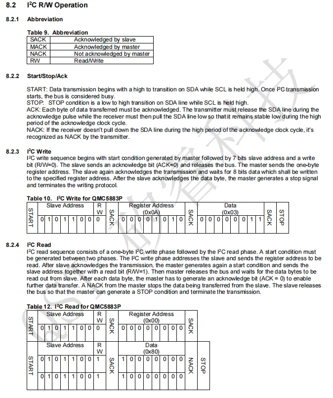
QMC5883P 's I ² C read and write protocol defines the START ( SDA jumps from high to low when SCL is high), STOP ( SDA jumps from low to high when SCL is high) and ACK / NACK response mechanism; the write operation process is start → slave address + write bit → register address → data → stop, and each stage is answered by the slave;For a read operation, you first need to write the specified register address in the write phase, then repeat the sequence of start → slave address + read bit; the master acknowledges each byte of data (sending NACK for the last byte), and finally generates a stop signal. Specific examples of read and write timings are also provided.
2.8 PCB Routing Notes
None.
III. Circuit Engineering
3.1 Circuit Source Engineering
To obtain the circuit source project, please follow the official account [Freak Embedded].
3.2 Module Usage Instructions
SCH_3-Axis Magnetometer Module Based on QMC5883P-V1.0.0_2026-03-27.pdf 2.2 MB
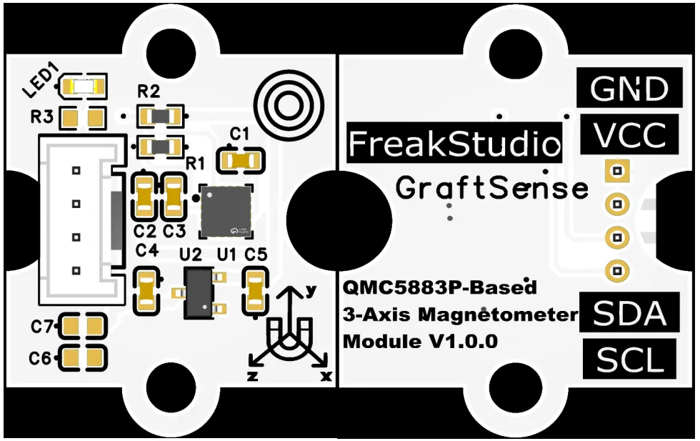
This module provides an I²C communication interface: it supports standard and fast-mode I²C communication, with a maximum data output rate of up to 1.5 kHz, enables reading and writing of magnetic field data via a fixed slave address, and is compatible with 3.3V level MCU s;The module integrates LDO voltage regulation, power filtering and I²C pull-up circuits, and is equipped with a power indicator. It supports magnetic field measurement ranging from ±2G to ±30G and compass heading accuracy of 1°~2°, which is suitable for magnetic field detection and positioning scenarios such as electronic compasses, pedestrian navigation, and wearable devices, providing stable and reliable magnetic field sensing and data interaction capabilities for the system.
3.3 Application Experiment
Here, we use the GraftPort-RP2040 development board for testing, and the QMC5883P-based three-axis magnetometer module communicates with the main controller via the I2C interface.
Here, we first use the HY2.0-4P connection cable to connect the module to the GraftPort-RP2040 development board's I2C0 interface:
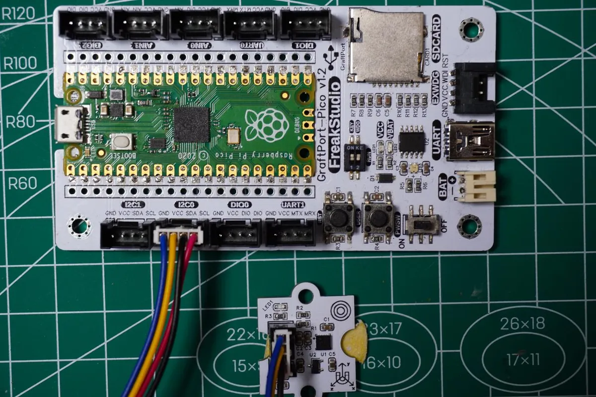
The module connections are shown in the following table:
Development Board Pins | Module Pins | Description |
Pin 4 |
|
|
Pin 5 |
|
|
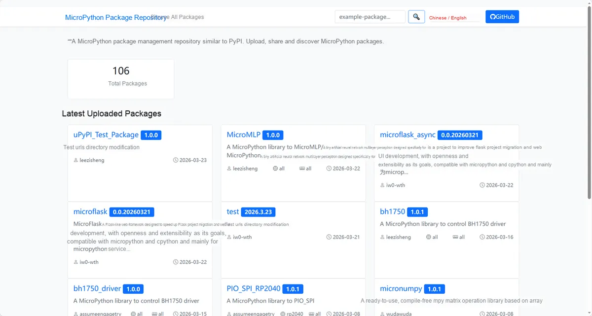
Here, we need to search for the relevant driver packages on uPyPI: https://upypi.net/zh/
Enter qmc5883l_driver to search, and the following will be displayed:
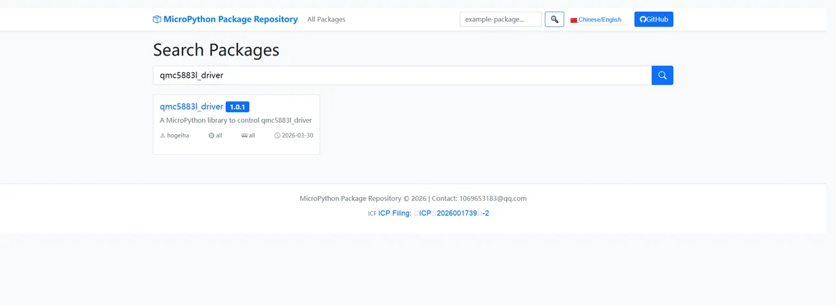
Click to copy the local installation command:
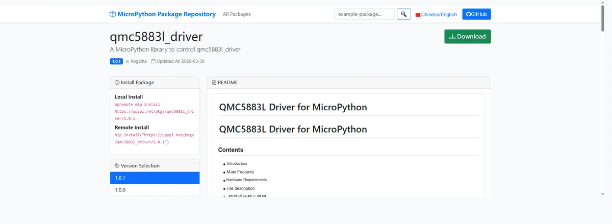
Import the module driver library code via the mip tool. Below are the usage commands for the mpremote tool:
mpremote mip install https://upypi.net/pkgs/qmc5883l_driver/1.0.0Import the MicroPython driver code for the QMC5883P-based 3-axis magnetometer module, then copy the following main.py code into our project:
# Python env   : MicroPython v1.23.0
# -*- coding: utf-8 -*-
# @Time    : 2025/9/8 4:52 PM
# @Author  : robert-hh
# @File    : main.py
# @Description : QMC5883P magnetometer sensor data reading example, obtaining scaled three-axis magnetic field data in real time over I2C and outputting it

# ======================================== Import Modules =========================================
import math
from machine import I2C, Pin
import time
from qmc5883p import QMC5883P

# ======================================== Global Variables ============================================

# SCL pin number
I2C_SCL_PIN = 5
# SDA pin number
I2C_SDA_PIN = 4
# I2C communication frequency
I2C_FREQ = 400_000
# QMC5883P default I2C address (decimal 13)
QMC5883P_ADDR = 0x2C

# ======================================== Functions ============================================

# ======================================== Custom Classes ============================================

# ======================================== Initialization configuration ===========================================

# Delay 3 seconds to ensure the QMC5883P sensor has finished initializing
time.sleep(3)
print("FreakStudio: QMC5883P magnetometer initialization start")

# Initialize the I2C bus in the specified style
i2c_bus = I2C(0, scl=Pin(I2C_SCL_PIN), sda=Pin(I2C_SDA_PIN), freq=I2C_FREQ)

# Start scanning for devices on the I2C bus
devices_list: list[int] = i2c_bus.scan()
print("START I2C SCANNER")

# Check the I2C device scan result
if len(devices_list) == 0:
    print("No i2c device !")
    raise SystemExit("I2C scan found no devices, program exited")
else:
    print("i2c devices found:", len(devices_list))

qmc5883 = None  # Initialize sensor object variable
for device in devices_list:
    if device == QMC5883P_ADDR:
        print("I2c hexadecimal address:", hex(device))
        try:
            qmc5883 = QMC5883P(i2c=i2c_bus)
            print("QMC5883P sensor initialization successful")
            break
        except Exception as e:
            print(f"QMC5883P Initialization failed: {e}")
            continue
else:
    raise Exception("No QMC5883P sensor found on I2C bus")

# Print sensor initialization complete message
print("FreakStudio: QMC5883P magnetometer initialized successfully")

# ========================================  Main Program  ============================================
# Infinite loop reading magnetometer sensor data
while True:
    # Read and print the scaled three-axis magnetic field data
    print(qmc5883.read_scaled())
    # Delay 300 milliseconds, then continue reading the next set of data
    time.sleep_ms(300)
Burn the code, open the terminal, and the output is as follows:
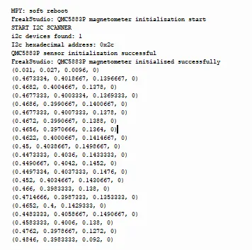
It can be seen that the three-axis magnetic field data can be output cyclically.
IV. Drivers
qmc5883l_driver-1.0.1.zip 10 KB
5. BOM & Recommended Alternative Parts
None.
6. Revision History
Document Version | Date of Revision | Modifier | Modified Content |
v1.0 | 2026-03-27 | Ling Gaoxing | Initialize the document |
v1.0.1 | 2026-04-05 | Li Zisheng | The homepage photo has not been taken, the production files have not been exported yet, and all other items have been sorted out completely. |
v1.0.2 | 2026-04-14 | Li Zisheng | The homepage photo has not been taken, the production files have not been exported yet, and all other items have been sorted out completely. |
v1.0.3 | 2026-04-21 | Li Zisheng | The production documents have not been exported yet, while all the others have been sorted out completely. |
v1.1 | 2026-04-23 | Xin Ruili | Create an open version of the document based on the internal document version v1.0.3. |
VII. Relevant Materials
7.1 Chip Datasheet
QMC5883P.pdf 1.0 MB
7.2 Unique Icons for PCB Silk Screen