Contents
- I. Module Introduction
- II. Introduction to Main Chips
- 2.1 Chip Overview
- 2.2 Pin Definition
- 2.3 Functional Block Diagram
- 2.4 Performance Parameters
- 2.5 Reference Circuit
- 2.6 Chip Configuration
- 2.7 Communication Interfaces and Related Protocols
- 2.8 PCB Routing Notes
- III. Circuit Engineering
- 3.1 Circuit Source Engineering
- 3.2 Module Usage Instructions
- 3.3 Application Experiment
- IV. Drivers
- 5. BOM & Recommended Alternative Parts
- 6. Revision History
- VII. Relevant Materials
- 7.1 Chip Datasheet
- 7.2 Unique Icons for PCB Silk Screen
I. Module Introduction
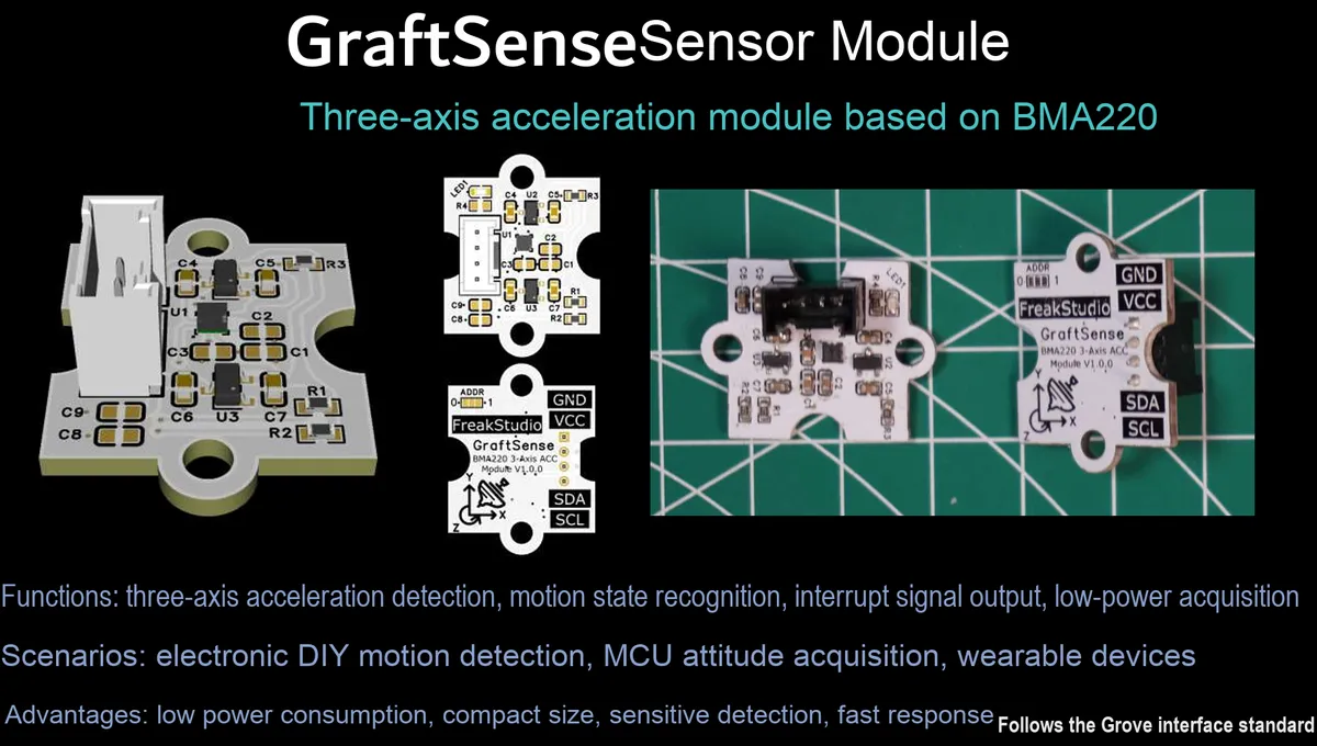
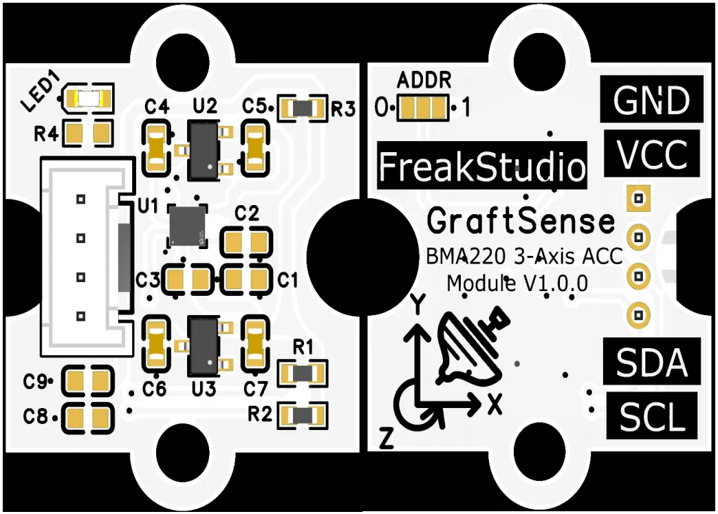
Triaxial acceleration module based on BMA220, which adopts the BMA220 chip solution, supports the I²C digital communication interface, can measure triaxial acceleration in the range of ±2g to ±16g, and provides high-precision detection capability. It has a built-in low-power circuit and special functions (motion/free fall detection), is equipped with power voltage regulation and filtering circuits, configures the device address via the ADDR pin, is compatible with 3.3V level MCUs, and is suitable for scenarios such as motion detection, attitude recognition and low-power IoT devices, providing stable and efficient inertial detection and interaction capabilities for the system.
II. Introduction to Main Chips
BMA220 is Bosch 's ultra-small size three-axis MEMS digital accelerometer , supporting ± 2g~ ± 16g programmable range, built-in low power consumption and interrupt detection function, compatible with I ² C interface, suitable for space-limited portable and IoT device scenarios.
2.1 Chip Overview
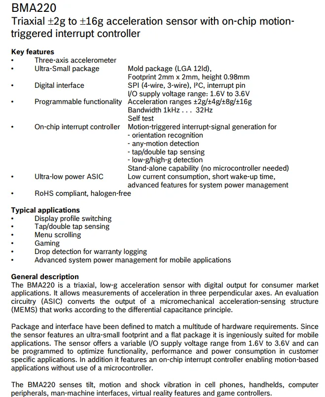
BMA220 core features and overview, covering a measurement range of ±2g to ±16g, a ultra-compact LGA-12 package (2mm×2mm×0.98mm), I²C / SPI digital interfaces, on-chip motion-triggered interrupt controller and ultra-low power characteristics. It is suitable for use cases such as gesture recognition, tap detection, and low-power mobile devices, providing high-precision inertial sensing capabilities for space-constrained portable applications.
2.2 Pin Definition
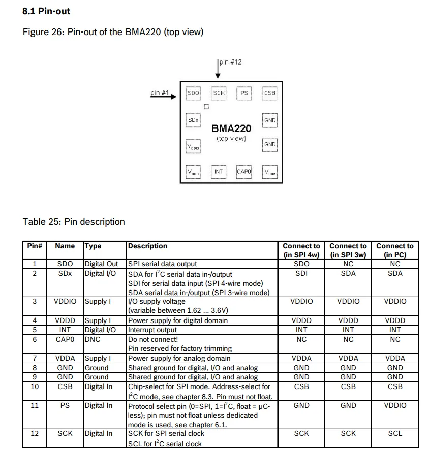
BMA220 's pinout diagram and function table clearly specify power pins (VDDIO / VDDD / VDDA), ground pins, I²C / SPI dual-interface communication pins and interrupt output pins (INT) as well as their functions and types. It also provides pin connection configurations for different communication modes, offering accurate pin definition reference for hardware design and driver development.
2.3 Functional Block Diagram
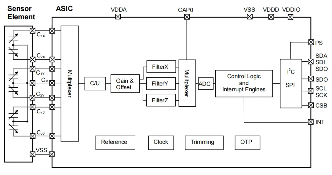
The variable capacitance of the sensor element changes with acceleration to generate a capacitance difference signal, which, after being gated by a multiplexer, is sent to the C / U (capacitance-to-voltage) conversion module to be converted into a voltage signal. After being processed by the gain and offset adjustment module, the signal is fed into the respective low-pass filters along the three axes of X / Y / Z. After being synchronized by the multiplexer, the signal is converted into a digital signal by the ADC. Finally, data calibration, processing and event triggering are completed in the control logic and interrupt engine module, and the acceleration data is output to an external system through the I²C or SPI communication interface. Meanwhile, the on-chip reference source, clock, trimming and OTP storage module ensure stable circuit operation and parameter storage.
2.4 Performance Parameters
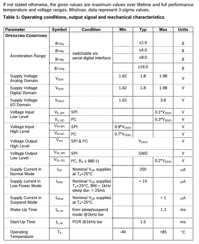
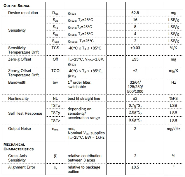
This is a MEMS Acceleration Sensor with selectable measurement ranges of ±2g/±4g/±8g/±16g, it operates on 1.62–1.98V for the analog/digital domain, 1.62–3.6V for the I/O domain, features a typical current of 250μA in normal mode, a resolution of 62.5mg, switchable bandwidth from 32 to 1000Hz, an operating temperature range of -40°C to + 85°C, and delivers low noise and stable temperature drift performance.
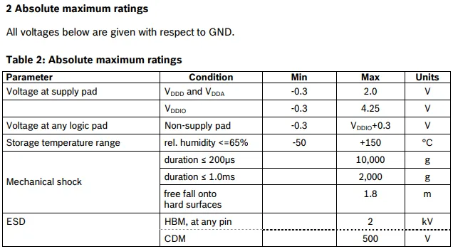
MEMS Acceleration Sensor Absolute Maximum Ratings Table: Analog / Digital Power Supply (V_DDA / V_DDD) Voltage Tolerance: -0.3~2.0V, I/O Power Supply (V_DDIO) Voltage Tolerance: -0.3~4.25V, Logic Pin Voltage Tolerance shall not exceed V_DDIO + 0.3V; Storage Temperature: -50~+ 150℃(Humidity ≤65% RH); For Mechanical Shock, it can withstand 10000g within 200μs, 2000g within 1ms, and a free fall from 1.8m;ESD protection is rated at HBM 2 kV and CDM 500 V.
2.5 Reference Circuit
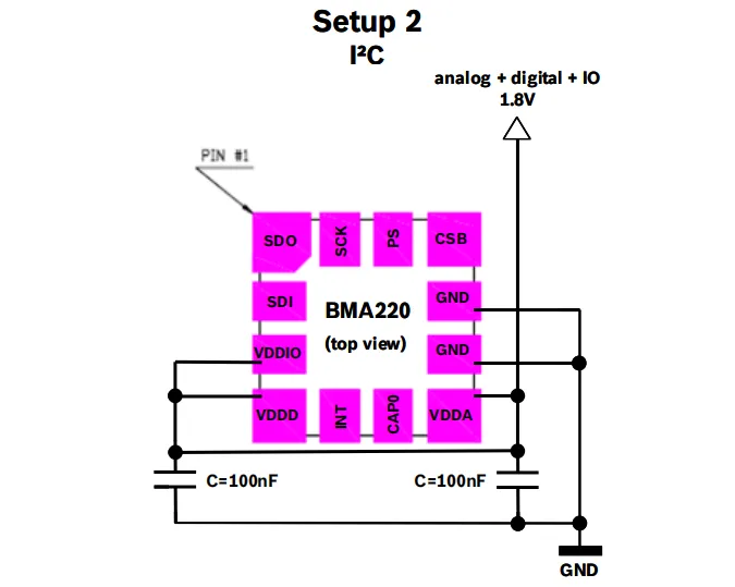
BMA220 Acceleration Sensor adopts I²C communication typical application circuit (top view): the analog/digital/ IO domains are uniformly powered by 1.8V, the VDDIO, VDDD, VDDA pins are all connected to 1.8V, and each is equipped with a 100nF decoupling capacitor to GND;GND pins are directly grounded, the CSB pin is connected to high level to select I²C communication mode, and the remaining pins (SDO, SCK, PS, SDI, INT, CAP0) are reserved by function.
2.6 Chip Configuration
None.
2.7 Communication Interfaces and Related Protocols
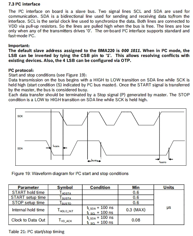
BMA220 features an I²C interface, acting as an I²C slave that communicates via SCL (clock) and SDA (bidirectional data); both lines require pull-up to VDD and support standard/fast mode. The default slave address is 000 1011, which can be configured via the CSB pin or OTP to avoid conflicts. Additionally, the timing waveforms and key timing parameters for the I²C start/stop conditions are provided (e. g., both the start hold/setup time and stop setup time are 0.6μs).
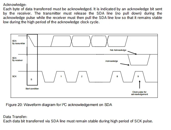
I²C Communication Acknowledgment and Data Transmission Specification: After the transmission of each byte of data, the receiver shall pull down the SDA line during the acknowledgment clock cycle to indicate an acknowledgment, and pull it high to indicate a non-acknowledgment; the transmitter shall release the SDA line during this period. It is also specified that each bit of data transmitted on the SDA line must remain stable during the high level of the SCK clock, with a corresponding timing waveform diagram provided.
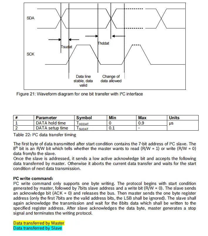
I²C Single-bit Transmission Timing and Write Command Protocol Description: During single-bit transmission, SDA shall meet a setup time of 0.1μs before the SCK rising edge, and a hold time of 0~0.9μs after the SCK falling edge; the first byte after the start condition consists of a 7-bit slave address plus a 1-bit R / W bit, and the slave pulls low SDA to acknowledge after address matching;I²C write commands only support single-byte write, with the procedure: Start → Address + Write Bit → Register Address → Data Byte → Stop, and each stage is acknowledged by the slave.
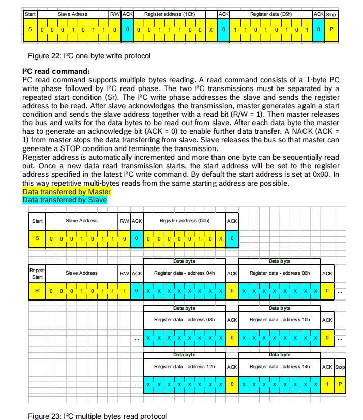
I²C Single-byte Write and Multi-byte Read Protocol Specification: The single-byte write procedure is Start → Slave Address + Write Bit → Register Address → Data Byte → Stop, with slave acknowledgment at each stage; for multi-byte read, the register address must first be transmitted via a write operation, followed by a repeated Start → Slave Address + Read Bit, after which the slave automatically increments the address and returns multi-byte data, with the master acknowledging each byte (no acknowledgment for the last byte), and the default start address is 0x00.
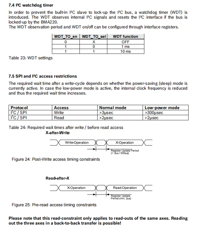
BMA220 I²C Watchdog and Communication Access Restrictions Description: The built-in I²C watchdog can be configured to disable / 1ms / 10ms timeout, which is used to reset the locked I²C interface;I²C / SPI read and write operations must meet the timing waiting requirements: in normal mode, wait > 3μs after a write operation and > 2μs before a read operation; in low-power mode, the waiting time after a write operation is extended to > 300μs, the waiting time for read operations remains unchanged, and the read restriction only applies to data reading of the same axis.
2.8 PCB Routing Notes
None.
III. Circuit Engineering
3.1 Circuit Source Engineering
To obtain the circuit source project, please follow the official account [Freak Embedded].
3.2 Module Usage Instructions
The schematic diagram of this module is shown below:
SCH_3-Axis Accelerometer Module Based on BMA220-V1.0.0_2026-03-27.pdf 2.3 MB
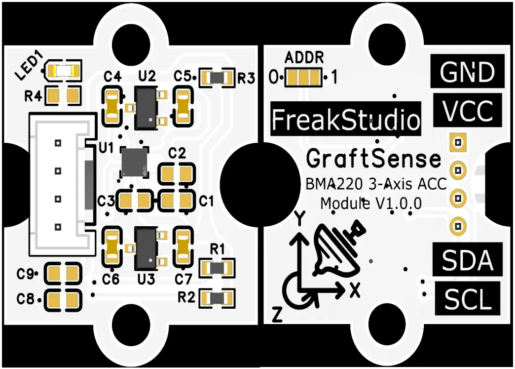
This module provides an I²C communication interface: it supports standard and fast-mode I²C communication. The device address can be configured via the ADDR pin to avoid bus conflicts, and it is compatible with 3.3V level MCUs. It supports reading and writing of three-axis acceleration data in the range of ±2g to ±16g, and features special functions including activity detection and free-fall detection. With a built-in low-power mechanism and communication watchdog, this module is applicable to scenarios such as motion detection, gesture recognition and low-power IoT devices, providing the system with stable and efficient inertial data interaction capabilities.
3.3 Application Experiment
Here, we use the GraftPort-RP2040 development board for testing, and the BMA220-based three-axis acceleration module uses the I2C interface to communicate with the main controller.
Here, we first use the HY2.0-4P connection cable to connect the module to the GraftPort-RP2040 development board's I2C0 interface:
The module connections are shown in the following table:
Development Board Pins | Module Pins | Description |
Pin 4 |
|
|
Pin 5 |
|
|
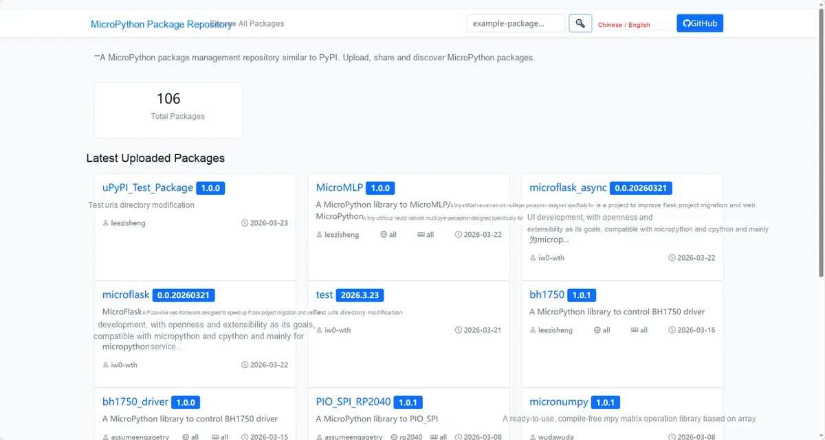
Here, we need to search for the relevant driver packages on uPyPI: https://upypi.net/zh/
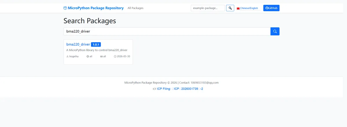
Enter bma220_driver to search, and the following will be displayed:
Click to copy the local installation command:
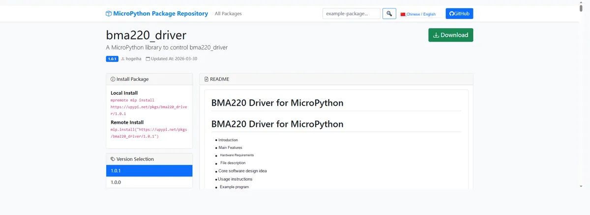
Import the module driver library code via the mip tool. Below are the usage commands for the mpremote tool:
mpremote mip install https://upypi.net/pkgs/bma220_driver/1.0.0Import the 3-axis acceleration module based on BMA220 - MicroPython driver code, then copy the following main.py code into our project:
# Python env   : MicroPython v1.23.0
# -*- coding: utf-8 -*-
# @Time    : 2026/3/16 2:00 PM
# @Author  :
# @File    : main.py
# @Description : BMA220 accelerometer multi-function test program, supporting tests of range, double-tap detection, filter bandwidth and other functions


# ======================================== Import Modules =========================================


# Import the time module, used for delay operations
import time

# Import the Pin and I2C classes from the machine module, used for hardware pin and I2C communication control
from machine import Pin, I2C

# Import the BMA220 sensor driver modules
from micropython_bma220 import bma220
from micropython_bma220 import bma220_tap_sensing
from micropython_bma220 import bma220_const as bma220_cnst
from micropython_bma220 import bma220_lowg_detection
from micropython_bma220 import bma220_orientation
from micropython_bma220 import bma220_slope


# ======================================== Global Variables ============================================


# BMA220 standard I2C address range: 0x0A corresponds to CSB pin connected to VDDIO, 0x0B corresponds to CSB pin connected to GND, covering all hardware configurations
TARGET_SENSOR_ADDRS = {0x0A, 0x0B}
# SCL pin number of the I2C0 bus on the RP2040 development board
I2C_SCL_PIN = 5
# SDA pin number of the I2C0 bus on the RP2040 development board
I2C_SDA_PIN = 4
# I2C communication frequency, set to 400000Hz (400KHz)
I2C_FREQ = 400000
# Initialize the sensor status flag, used to determine whether BMA220 was initialized successfully
sensor_initialized = False
# Store the found BMA220 device address
found_addr = None

# ======================================== Functions ============================================


def test_acc_range() -> None:
    """
    Test the range setting function of the BMA220 accelerometer, iterate through all supported ranges and output acceleration data
    Args:
        None

    Raises:
        KeyboardInterrupt: Triggered when the user presses Ctrl+C, used to stop the test

    Notes:
        During the test, X/Y/Z three-axis acceleration data is output in a loop, with an interval of 0.5 seconds between outputs, and each range is tested 10 times

    ==========================================
    Test the acceleration range setting function of BMA220 sensor, traverse all supported ranges and output acceleration data
    Args:
        None

    Raises:
        KeyboardInterrupt: Triggered when the user presses Ctrl+C to stop the test

    Notes:
        During the test, X/Y/Z three-axis acceleration data will be output cyclically, with an interval of 0.5 seconds for each output, and each range is tested 10 times
    """
    # Print the test start message
    print("\n=== Start testing acceleration range ===")
    # Initialize the BMA220 sensor instance
    bma = bma220.BMA220(i2c_bus)
    # Set the initial acceleration range to 16g
    bma.acc_range = bma220.ACC_RANGE_16

    try:
        # Infinite loop to test all ranges
        while True:
            # Iterate over all supported acceleration ranges
            for acc_range in bma220.acc_range_values:
                # Print the current range setting
                print(f"Current acceleration range setting: {bma.acc_range}")
                # Test each range 10 times
                for _ in range(10):
                    # Get X/Y/Z three-axis acceleration data
                    accx, accy, accz = bma.acceleration
                    # Print formatted acceleration data
                    print(f"x:{accx:.2f}m/s², y:{accy:.2f}m/s², z:{accz:.2f}m/s²")
                    # Delay 0.5 seconds
                    time.sleep(0.5)
                # Set the next acceleration range
                bma.acc_range = acc_range
    except KeyboardInterrupt:
        # Print the test stop message
        print("\n=== Acceleration range test stopped ===")


def test_tap_sensing() -> None:
    """
    Test the double-tap detection function of the BMA220 sensor, configure the related parameters and output the interrupt trigger status in real time
    Args:
        None

    Raises:
        KeyboardInterrupt: Triggered when the user presses Ctrl+C, used to stop the test

    Notes:
        During the test, the double-tap interrupt trigger status is output every 0.5 seconds; tap the sensor to trigger detection

    ==========================================
    Test the double tap detection function of BMA220 sensor, configure relevant parameters and output interrupt trigger status in real time
    Args:
        None

    Raises:
        KeyboardInterrupt: Triggered when the user presses Ctrl+C to stop the test

    Notes:
        During the test, the double tap interrupt trigger status is output every 0.5 seconds, and the sensor needs to be tapped to trigger detection
    """
    # Print the test start message
    print("\n=== Start testing double tap sensing ===")
    # Initialize the BMA220 double-tap detection instance
    bma = bma220_tap_sensing.BMA220_TAP(i2c_bus)

    # Configure double-tap detection parameters: set the latch mode to 1 second
    bma.latched_mode = bma220_cnst.LATCH_FOR_1S
    # Enable X-axis double-tap detection
    bma.tt_x_enabled = bma220_tap_sensing.TT_X_ENABLED
    # Enable Y-axis double-tap detection
    bma.tt_y_enabled = bma220_tap_sensing.TT_Y_ENABLED
    # Enable Z-axis double-tap detection
    bma.tt_z_enabled = bma220_tap_sensing.TT_Z_ENABLED
    # Set the double-tap detection duration to 500 milliseconds
    bma.tt_duration = bma220_tap_sensing.TIME_500MS

    try:
        # Output the double-tap interrupt status in an infinite loop
        while True:
            # Print the double-tap interrupt trigger status
            print(f"Double Tap Interrupt Triggered: {bma.tt_interrupt}")
            # Delay 0.5 seconds
            time.sleep(0.5)
    except KeyboardInterrupt:
        # Print the test stop message
        print("\n=== Double tap sensing test stopped ===")


def test_filter_bandwidth() -> None:
    """
    Test the filter bandwidth setting function of the BMA220 sensor, iterate through all bandwidths and output acceleration data
    Args:
        None

    Raises:
        KeyboardInterrupt: Triggered when the user presses Ctrl+C, used to stop the test

    Notes:
        During the test, X/Y/Z three-axis acceleration data is output in a loop; each bandwidth configuration is tested 10 times with an interval of 0.5 seconds

    ==========================================
    Test the filter bandwidth setting function of BMA220 sensor, traverse all bandwidths and output acceleration data
    Args:
        None

    Raises:
        KeyboardInterrupt: Triggered when the user presses Ctrl+C to stop the test

    Notes:
        During the test, X/Y/Z three-axis acceleration data will be output cyclically, each bandwidth configuration is tested 10 times with an interval of 0.5 seconds
    """
    # Print the test start message
    print("\n=== Start testing filter bandwidth ===")
    # Initialize the BMA220 sensor instance
    bma = bma220.BMA220(i2c_bus)
    # Set the initial filter bandwidth to 500Hz
    bma.filter_bandwidth = bma220.ACCEL_500HZ

    try:
        # Test all filter bandwidths in an infinite loop
        while True:
            # Iterate through all supported filter bandwidths
            for filter_bandwidth in bma220.filter_bandwidth_values:
                # Print the current filter bandwidth setting
                print(f"Current Filter bandwidth setting: {bma.filter_bandwidth}")
                # Test each bandwidth 10 times
                for _ in range(10):
                    # Get X/Y/Z three-axis acceleration data
                    accx, accy, accz = bma.acceleration
                    # Print formatted acceleration data
                    print(f"x:{accx:.2f}m/s², y:{accy:.2f}m/s², z:{accz:.2f}m/s²")
                    # Delay 0.5 seconds
                    time.sleep(0.5)
                # Set the next filter bandwidth
                bma.filter_bandwidth = filter_bandwidth
    except KeyboardInterrupt:
        # Print the test stop message
        print("\n=== Filter bandwidth test stopped ===")


def test_latched_mode() -> None:
    """
    Test the latch mode setting function of the BMA220 sensor, iterate through all latch modes and output acceleration data
    Args:
        None

    Raises:
        KeyboardInterrupt: Triggered when the user presses Ctrl+C, used to stop the test

    Notes:
        During the test, X/Y/Z three-axis acceleration data is output in a loop; each latch mode is tested 10 times with an interval of 0.5 seconds

    ==========================================
    Test the latched mode setting function of BMA220 sensor, traverse all latched modes and output acceleration data
    Args:
        None

    Raises:
        KeyboardInterrupt: Triggered when the user presses Ctrl+C to stop the test

    Notes:
        During the test, X/Y/Z three-axis acceleration data will be output cyclically, each latched mode is tested 10 times with an interval of 0.5 seconds
    """
    # Print the test start message
    print("\n=== Start testing latched mode ===")
    # Initialize the BMA220 sensor instance
    bma = bma220.BMA220(i2c_bus)
    # Set the initial latch mode to 2 seconds
    bma.latched_mode = bma220.LATCH_FOR_2S

    try:
        # Test all latch modes in an infinite loop
        while True:
            # Iterate through all supported latch modes
            for latched_mode in bma220.latched_mode_values:
                # Print the current latch mode setting
                print(f"Current Latched mode setting: {bma.latched_mode}")
                # Test each latch mode 10 times
                for _ in range(10):
                    # Get X/Y/Z three-axis acceleration data
                    accx, accy, accz = bma.acceleration
                    # Print formatted acceleration data
                    print(f"x:{accx:.2f}m/s², y:{accy:.2f}m/s², z:{accz:.2f}m/s²")
                    # Delay 0.5 seconds
                    time.sleep(0.5)
                # Set the next latch mode
                bma.latched_mode = latched_mode
    except KeyboardInterrupt:
        # Print the test stop message
        print("\n=== Latched mode test stopped ===")


def test_lowg_detection() -> None:
    """
    Test the low-g detection function of the BMA220 sensor, configure the latch mode and output the interrupt trigger status in real time
    Args:
        None

    Raises:
        KeyboardInterrupt: Triggered when the user presses Ctrl+C, used to stop the test

    Notes:
        During the test, the low-g interrupt trigger status is output every 0.5 seconds; the sensor must be placed in a low-g state to trigger detection

    ==========================================
    Test the low gravity detection function of BMA220 sensor, configure latched mode and output interrupt trigger status in real time
    Args:
        None

    Raises:
        KeyboardInterrupt: Triggered when the user presses Ctrl+C to stop the test

    Notes:
        During the test, the low gravity interrupt trigger status is output every 0.5 seconds, and the sensor needs to be in a low gravity state to trigger detection
    """
    # Print the test start message
    print("\n=== Start testing low gravity detection ===")
    # Initialize the BMA220 low-g detection instance
    bma = bma220_lowg_detection.BMA220_LOWG_DETECTION(i2c_bus)
    # Set the latch mode to 1 second
    bma.latched_mode = bma220_cnst.LATCH_FOR_1S

    try:
        # Output the low-g interrupt status in an infinite loop
        while True:
            # Print the low-g interrupt trigger status
            print(f"Low G Interrupt Triggered: {bma.lowg_interrupt}")
            # Delay 0.5 seconds
            time.sleep(0.5)
    except KeyboardInterrupt:
        # Print the test stop message
        print("\n=== Low gravity detection test stopped ===")


def test_orientation() -> None:
    """
    Test the orientation detection function of the BMA220 sensor, configure the related parameters and output the interrupt trigger status in real time
    Args:
        None

    Raises:
        KeyboardInterrupt: Triggered when the user presses Ctrl+C, used to stop the test

    Notes:
        During the test, 3 orientation blocking modes are iterated; each mode is tested 50 times with an output interval of 0.1 seconds

    ==========================================
    Test the orientation detection function of BMA220 sensor, configure relevant parameters and output interrupt trigger status in real time
    Args:
        None

    Raises:
        KeyboardInterrupt: Triggered when the user presses Ctrl+C to stop the test

    Notes:
        During the test, 3 orientation blocking modes are traversed, each mode is tested 50 times, and each output interval is 0.1 seconds
    """
    # Print the test start message
    print("\n=== Start testing orientation detection ===")
    # Initialize the BMA220 orientation detection instance
    bma = bma220_orientation.BMA220_ORIENTATION(i2c_bus)
    # Set the latch mode to 1 second
    bma.latched_mode = bma220_cnst.LATCH_FOR_1S
    # Set the initial orientation blocking mode to MODE1
    bma.orientation_blocking = bma220_orientation.MODE1

    try:
        # Test all orientation blocking modes in an infinite loop
        while True:
            # Iterate through the 3 orientation blocking modes
            for orientation_blocking in (1, 2, 3):
                # Print the current orientation blocking mode setting
                print(f"Current Orientation blocking setting: {bma.orientation_blocking}")
                # Test each mode 50 times
                for _ in range(50):
                    # Print the orientation interrupt trigger status
                    print(f"Orientation Interrupt Triggered: {bma.orientation_interrupt}")
                    # Delay 0.1 seconds
                    time.sleep(0.1)
                # Set the next orientation blocking mode
                bma.orientation_blocking = orientation_blocking
    except KeyboardInterrupt:
        # Print the test stop message
        print("\n=== Orientation detection test stopped ===")


def test_basic_acceleration() -> None:
    """
    Test the basic acceleration data reading function of the BMA220 sensor, output X/Y/Z three-axis acceleration data in real time
    Args:
        None

    Raises:
        KeyboardInterrupt: Triggered when the user presses Ctrl+C, used to stop the test

    Notes:
        During the test, acceleration data is output continuously with an interval of 0.5 seconds between outputs; no parameter configuration is changed

    ==========================================
    Test the basic acceleration data reading function of BMA220 sensor, output X/Y/Z three-axis acceleration data in real time
    Args:
        None

    Raises:
        KeyboardInterrupt: Triggered when the user presses Ctrl+C to stop the test

    Notes:
        During the test, acceleration data is continuously output, with an interval of 0.5 seconds for each output, and no parameter configuration modification
    """
    # Print the test start message
    print("\n=== Start testing basic acceleration reading ===")
    # Initialize the BMA220 sensor instance
    bma = bma220.BMA220(i2c_bus)

    try:
        # Output acceleration data in an infinite loop
        while True:
            # Get X/Y/Z three-axis acceleration data
            accx, accy, accz = bma.acceleration
            # Print formatted acceleration data
            print(f"x:{accx:.2f}m/s², y:{accy:.2f}m/s², z:{accz:.2f}m/s²")
            # Delay 0.5 seconds
            time.sleep(0.5)
    except KeyboardInterrupt:
        # Print the test stop message
        print("\n=== Basic acceleration reading test stopped ===")


def test_sleep_duration() -> None:
    """
    Test the sleep duration setting function of the BMA220 sensor, iterate through all sleep durations and output acceleration data
    Args:
        None

    Raises:
        KeyboardInterrupt: Triggered when the user presses Ctrl+C, used to stop the test

    Notes:
        During the test, X/Y/Z three-axis acceleration data is output in a loop; each sleep duration is tested 10 times with an interval of 0.5 seconds

    ==========================================
    Test the sleep duration setting function of BMA220 sensor, traverse all sleep durations and output acceleration data
    Args:
        None

    Raises:
        KeyboardInterrupt: Triggered when the user presses Ctrl+C to stop the test

    Notes:
        During the test, X/Y/Z three-axis acceleration data will be output cyclically, each sleep duration is tested 10 times with an interval of 0.5 seconds
    """
    # Print the test start message
    print("\n=== Start testing sleep duration ===")
    # Initialize the BMA220 sensor instance
    bma = bma220.BMA220(i2c_bus)
    # Set the initial sleep duration to 10 milliseconds
    bma.sleep_duration = bma220.SLEEP_10MS

    try:
        # Test all sleep durations in an infinite loop
        while True:
            # Iterate through all supported sleep durations
            for sleep_duration in bma220.sleep_duration_values:
                # Print the current sleep duration setting
                print(f"Current Sleep duration setting: {bma.sleep_duration}")
                # Test each sleep duration 10 times
                for _ in range(10):
                    # Get X/Y/Z three-axis acceleration data
                    accx, accy, accz = bma.acceleration
                    # Print formatted acceleration data
                    print(f"x:{accx:.2f}m/s², y:{accy:.2f}m/s², z:{accz:.2f}m/s²")
                    # Delay 0.5 seconds
                    time.sleep(0.5)
                # Set the next sleep duration
                bma.sleep_duration = sleep_duration
    except KeyboardInterrupt:
        # Print the test stop message
        print("\n=== Sleep duration test stopped ===")


def test_slope_sign() -> None:
    """
    Test the slope sign setting function of the BMA220 sensor, configure the related parameters and output the slope interrupt information in real time
    Args:
        None

    Raises:
        KeyboardInterrupt: Triggered when the user presses Ctrl+C, used to stop the test

    Notes:
        During the test, all slope signs are iterated; each sign is tested 10 times, outputting the slope interrupt status and three-axis slope information

    ==========================================
    Test the slope sign setting function of BMA220 sensor, configure relevant parameters and output slope interrupt information in real time
    Args:
        None

    Raises:
        KeyboardInterrupt: Triggered when the user presses Ctrl+C to stop the test

    Notes:
        During the test, all slope signs are traversed, each sign is tested 10 times, and the slope interrupt status and three-axis slope information are output
    """
    # Print the test start message
    print("\n=== Start testing slope sign ===")
    # Initialize the BMA220 slope detection instance
    bma = bma220_slope.BMA220_SLOPE(i2c_bus)

    # Configure slope detection parameters: set the latch mode to 1 second
    bma.latched_mode = bma220_cnst.LATCH_FOR_1S
    # Enable X-axis slope detection
    bma.slope_x_enabled = bma220_slope.SLOPE_X_ENABLED
    # Enable Y-axis slope detection
    bma.slope_y_enabled = bma220_slope.SLOPE_Y_ENABLED
    # Enable Z-axis slope detection
    bma.slope_z_enabled = bma220_slope.SLOPE_Z_ENABLED
    # Set the initial slope sign to negative
    bma.slope_sign = bma220_slope.SLOPE_SIGN_NEGATIVE
    # Set the slope threshold to 8
    bma.slope_threshold = 8

    try:
        # Test all slope signs in an infinite loop
        while True:
            # Iterate through all supported slope signs
            for slope_sign in bma220_slope.slope_sign_values:
                # Print the current slope sign setting
                print(f"Current Slope sign setting: {bma.slope_sign}")
                # Test each slope sign 10 times
                for _ in range(10):
                    # Print the slope interrupt trigger status
                    print(f"Slope Interrupt Triggered: {bma.slope_interrupt}")
                    # Get the X/Y/Z three-axis slope interrupt information
                    infox, infoy, infoz = bma.slope_interrupt_info
                    # Print the three-axis slope information
                    print(f"Slope x:{infox}, y:{infoy}, z:{infoz}")
                    # Delay 0.5 seconds
                    time.sleep(0.5)
                # Set the next slope sign
                bma.slope_sign = slope_sign
    except KeyboardInterrupt:
        # Print the test stop message
        print("\n=== Slope sign test stopped ===")


def test_slope_x() -> None:
    """
    Test the X-axis slope detection function of the BMA220 sensor, configure the related parameters and output the interrupt trigger status in real time
    Args:
        None

    Raises:
        KeyboardInterrupt: Triggered when the user presses Ctrl+C, used to stop the test

    Notes:
        During the test, the X-axis slope interrupt trigger status is output every 0.5 seconds; only X-axis slope detection is enabled

    ==========================================
    Test the X-axis slope detection function of BMA220 sensor, configure relevant parameters and output interrupt trigger status in real time
    Args:
        None

    Raises:
        KeyboardInterrupt: Triggered when the user presses Ctrl+C to stop the test

    Notes:
        During the test, the X-axis slope interrupt trigger status is output every 0.5 seconds, and only X-axis slope detection is enabled
    """
    # Print the test start message
    print("\n=== Start testing X-axis slope detection ===")
    # Initialize the BMA220 slope detection instance
    bma = bma220_slope.BMA220_SLOPE(i2c_bus)
    # Set the latch mode to 2 seconds
    bma.latched_mode = bma220_cnst.LATCH_FOR_2S
    # Enable X-axis slope detection
    bma.slope_x_enabled = bma220_slope.SLOPE_X_ENABLED

    try:
        # Output the X-axis slope interrupt status in an infinite loop
        while True:
            # Print the slope interrupt trigger status
            print(f"Slope Interrupt Triggered: {bma.slope_interrupt}")
            # Delay 0.5 seconds
            time.sleep(0.5)
    except KeyboardInterrupt:
        # Print the test stop message
        print("\n=== X-axis slope detection test stopped ===")


def main_menu() -> None:
    """
    Main program menu, providing an entry for selecting each BMA220 sensor function test, supporting user interaction to select test items
    Args:
        None

    Raises:
        ValueError: Raised when the user enters non-numeric characters, prompting an input error
        Exception: Raised when an unknown error occurs during testing, outputting the error message

    Notes:
        Enter 0 to exit the program, enter 1-10 to select the corresponding test item, enter anything else to get an invalid prompt

    ==========================================
    Program main menu, providing selection entry for each function test of BMA220 sensor, supporting user interactive selection of test items
    Args:
        None

    Raises:
        ValueError: Triggered when the user enters non-numeric characters, prompting input error
        Exception: Triggered when an unknown error occurs during the test, outputting error information

    Notes:
        The user enters 0 to exit the program, 1-10 to select the corresponding test item, and other inputs to prompt invalid
    """
    # Define the main menu prompt text
    menu = """

====================================
BMA220 Function Test Menu
Please enter the corresponding number to select the test function:
1 - Acceleration Range Test
2 - Double Tap Sensing Test
3 - Filter Bandwidth Test
4 - Latched Mode Test
5 - Low Gravity Detection Test
6 - Orientation Detection Test
7 - Basic Acceleration Reading
8 - Sleep Duration Test
9 - Slope Sign Test
10 - X-axis Slope Detection Test
0 - Exit Program
====================================
"""
    # Display the main menu in an infinite loop
    while True:
        # Print the main menu
        print(menu)
        try:
            # Get the user's input choice
            choice = int(input("Please enter your selection (0-10): "))
            # Determine the user's choice
            if choice == 0:
                # Print the program exit message
                print("Program exited")
                # Exit the loop
                break
            elif choice == 1:
                # Run the acceleration range test
                test_acc_range()
            elif choice == 2:
                # Run the double-tap detection test
                test_tap_sensing()
            elif choice == 3:
                # Run the filter bandwidth test
                test_filter_bandwidth()
            elif choice == 4:
                # Run the latch mode test
                test_latched_mode()
            elif choice == 5:
                # Run the low-g detection test
                test_lowg_detection()
            elif choice == 6:
                # Run the orientation detection test
                test_orientation()
            elif choice == 7:
                # Run the basic acceleration reading test
                test_basic_acceleration()
            elif choice == 8:
                # Run the sleep duration test
                test_sleep_duration()
            elif choice == 9:
                # Run the slope sign test
                test_slope_sign()
            elif choice == 10:
                # Run the X-axis slope detection test
                test_slope_x()
            else:
                # Print the invalid input message
                print("Invalid input, please enter a number between 0 and 10")
        except ValueError:
            # Print the input error message
            print("Input error, please enter a number")
        except Exception as e:
            # Print the runtime error message
            print(f"Program error: {e}")


# ======================================== Custom Classes ============================================


# ======================================== Initialization configuration ===========================================


# Delay 3 seconds, wait for the sensor initialization to complete
time.sleep(3)
# Print the initialization message
print("FreakStudio: BMA220 sensor test initialization")

# Initialize the I2C bus, use the RP2040's I2C0, specify the SCL and SDA pins, communication frequency 400KHz
i2c_bus = I2C(0, scl=Pin(I2C_SCL_PIN), sda=Pin(I2C_SDA_PIN), freq=I2C_FREQ)

# Scan all devices on the I2C bus, return a list of device addresses
devices_list: list[int] = i2c_bus.scan()
# Print the I2C scan start message
print("START I2C SCANNER")

# Check whether the I2C scan result is empty
if len(devices_list) == 0:
    # Print the no I2C device message
    print("No i2c device !")
    # Raise a system exit exception to terminate the program
    raise SystemExit("I2C scan found no devices, program exited")
else:
    # Print the number of I2C devices found
    print("i2c devices found:", len(devices_list))
    # Print all scanned I2C device addresses (hexadecimal)
    print(f"Scanned I2C addresses: {[hex(addr) for addr in devices_list]}")

# Iterate through all scanned I2C device addresses
for device in devices_list:
    # Determine whether the current address is within the BMA220 standard address range
    if device in TARGET_SENSOR_ADDRS:
        # Record the found BMA220 address
        found_addr = device
        # Print the found BMA220 standard address
        print(f"Found BMA220 standard address: {hex(found_addr)}")
        try:
            # Initialize the BMA220 sensor instance, verify that communication is normal
            test_sensor = bma220.BMA220(i2c=i2c_bus)
            # Print the sensor initialization success message
            print("Target sensor (BMA220) initialization successful")
            # Mark the sensor initialization as successful
            sensor_initialized = True
            # Exit the address traversal loop
            break
        except Exception as e:
            # Print sensor initialization failure message and error information
            print(f"Sensor Initialization failed at address {hex(found_addr)}: {e}")
            # Continue to the next address
            continue
# Check whether the sensor was initialized successfully
if not sensor_initialized:
    # Raise an exception indicating the BMA220 sensor was not found
    raise Exception(
        f"No BMA220 sensor found on I2C bus! "
        f"Expected addresses: {[hex(addr) for addr in TARGET_SENSOR_ADDRS]}, "
        f"Scanned addresses: {[hex(addr) for addr in devices_list]}"
    )


# ========================================  Main Program  ============================================


# Program entry point, executed when this script is run directly
if __name__ == "__main__":
    # Print program start message
    print("BMA220 Multi-function Test Program (RP2040)")
    # Call the main menu function
    main_menu()
Burn the code, open the terminal, and the output is as follows:
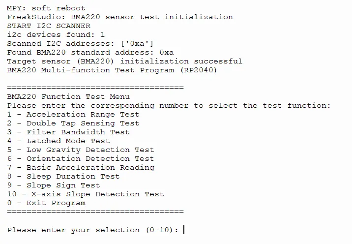
The code provided above offers an interactive main menu that allows users to select all core functions including acceleration measurement range test, double-tap detection, filter bandwidth, latch mode, low-gravity detection, orientation recognition, basic acceleration reading, sleep duration, slope sign, and X-axis slope detection. It outputs three-axis data or interrupt trigger status in real time, and a single test can be stopped via Ctrl+ C to complete the verification and debugging of the full functions of the sensor.
We input different options, and the output is as follows:
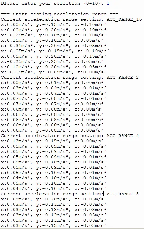
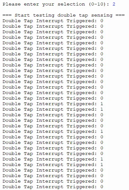
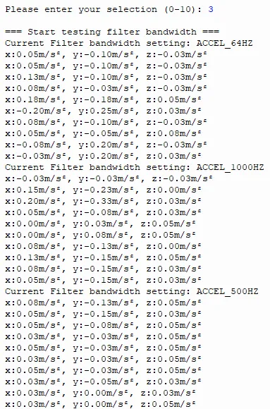
It can be seen that we can select and output normally.
IV. Drivers
bma220_driver-1.0.1.zip 43 KB
5. BOM & Recommended Alternative Parts
None.
6. Revision History
Document Version | Date of Revision | Modifier | Modified Content |
v1.0 | 2026-03-27 | Ling Gaoxing | Initialize the document |
v1.0.1 | 2026-04-05 | Li Zisheng | The homepage photo has not been taken, the production files have not been exported yet, and all other items have been sorted out completely. |
v1.0.2 | 2026-04-21 | Li Zisheng | The production documents have not been exported yet, while all the others have been sorted out completely. |
v1.1 | 2026-04-23 | Xin Ruili | Create an open version of the document, based on the internal document version v1.0.2. |
VII. Relevant Materials
7.1 Chip Datasheet
BMA220.pdf 1.2 MB
7.2 Unique Icons for PCB Silk Screen