Contents
- I. Module Introduction
- II. Introduction to Main Chips
- 2.1 Chip Overview
- 2.2 Pin Definition
- 2.3 Functional Block Diagram
- 2.4 Performance Parameters
- 2.5 Reference Circuit
- 2.6 Chip Configuration
- 2.7 Communication Interfaces and Related Protocols
- 2.8 PCB Routing Notes
- III. Circuit Engineering
- 3.1 Circuit Source Engineering
- 3.2 Module Usage Instructions
- 3.3 Application Experiment
- IV. Drivers
- 5. BOM & Recommended Alternative Parts
- 6. Revision History
- VII. Relevant Materials
- 7.1 Chip Datasheet
- 7.2 Unique Icons for PCB Silk Screen
I. Module Introduction
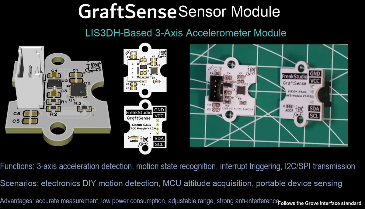
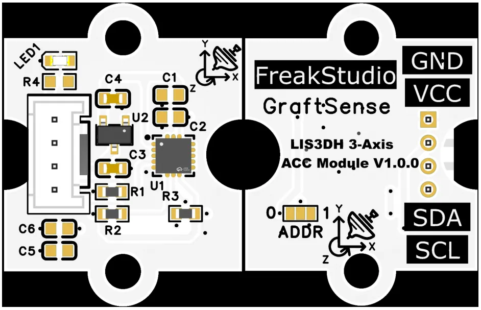
Based on the LIS3DH three-axis acceleration module, it adopts the LIS3DH chip solution, supports two digital communication interfaces including I²C, can measure three-axis acceleration in the range of ±2g to ±16g, and its 12-bit effective resolution delivers high-precision detection capability. Built with a FIFO buffer and low-power circuit, equipped with a 3.3V LDO voltage regulator and power filtering circuit, it configures the device address via the ADDR pin, is compatible with 3.3V level MCUs, and is suitable for scenarios such as motion detection, posture recognition, vibration monitoring and portable devices, providing stable and efficient inertial detection and interaction capabilities for the system.
II. Introduction to Main Chips
LIS3DH is a 12-bit three-axis MEMS digital accelerometer launched by STMicroelectronics , supporting ± 2g~ ± 16g range selection, built-in FIFO and low power consumption characteristics, compatible with I ² C / SPI interface, can realize motion/tapping/free fall detection, suitable for high-precision inertia and attitude perception scenarios.
2.1 Chip Overview
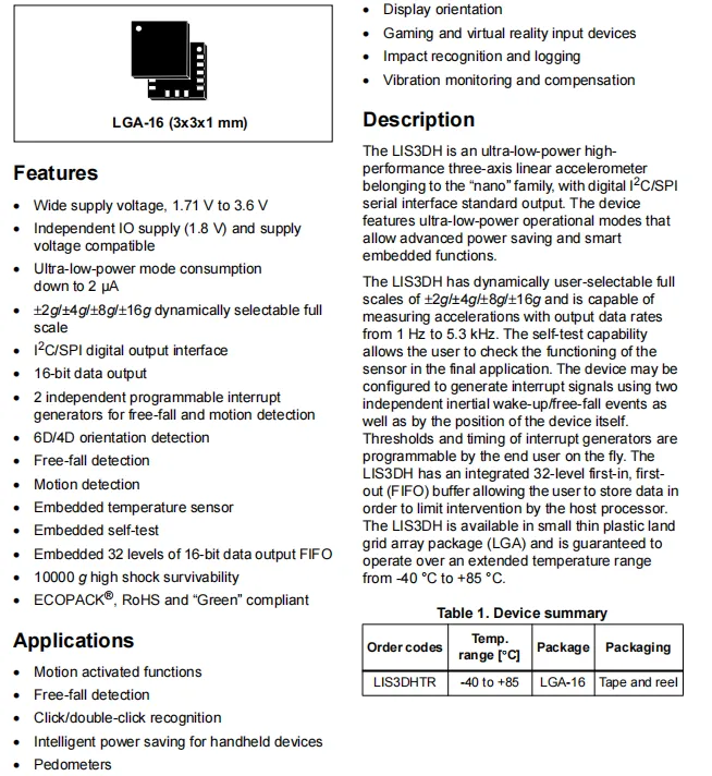
LIS3DH features core specifications covering a wide supply voltage range of 1.71V to 3.6V, ultra-low power consumption (as low as 2μA), selectable measurement ranges from ±2g to ±16g, 16-bit data output, built-in 32-level FIFO and temperature sensor, as well as special functions including tap detection, free-fall detection and motion posture detection; it also features a compact LGA package and an operating temperature range of -40°C to + 85°C, making it ideal for motion sensing, inertial detection and low-power portable device applications.
2.2 Pin Definition
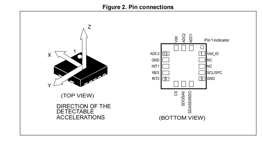
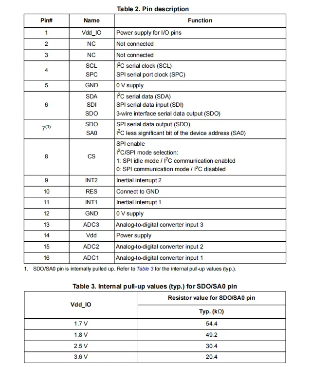
The pinout and function table of the LIS3DH clearly specify power supply pins (Vdd / Vdd_IO), ground pins, I²C / SPI dual-interface communication pins, interrupt output pins (INT1 / INT2) and address selection pin (SA0) in terms of their functions and types, and also provides the internal pull-up resistance value of the SDO / SA0 pin, offering accurate pin definition reference for hardware design and driver development.
2.3 Functional Block Diagram
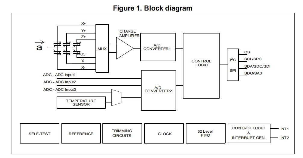
The LIS3DH internally uses a three-axis MEMS sensor to detect X / Y / Z axis acceleration signals. After being processed by a multiplexer and a charge amplifier, the signals are converted into 16-bit digital values by an ADC. It also has a built-in temperature sensor and an auxiliary ADC, and the data can be stored in a 32-level FIFO buffer. Then, the control and interrupt logic module handles special detection events such as tap and free fall. Finally, the acceleration data and interrupt status are output through the I²C / SPI serial interface, providing the system with high-precision, low-power motion and attitude detection capabilities.
2.4 Performance Parameters
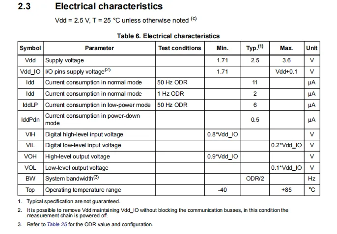
LIS3DH electrical characteristic parameter table covers a 1.71V~3.6V supply voltage range, ultra-low power consumption (as low as 2μA in measurement mode and 0.5μA in standby mode), digital I/O level compatibility, the correlation between bandwidth and output data rate (BW = ODR /2), and an operating temperature range of -40℃~+ 85℃. It also specifies typical operating current and electrical parameter constraints, providing accurate performance reference for hardware design and low-power applications.
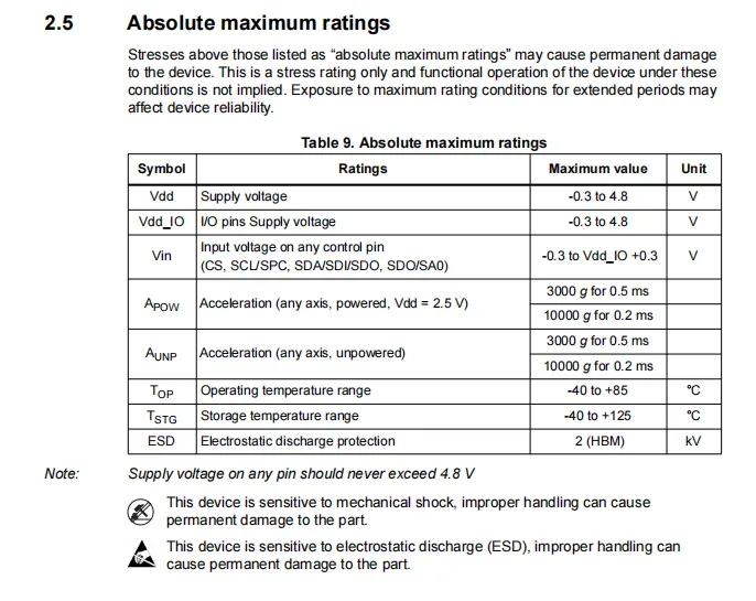
LIS3DH absolute maximum ratings table clearly defines the device's ultimate tolerance parameters: including a supply voltage margin of -0.3V to 4.8V, impact resistance of 3000g to 10000g, storage temperature range of -40℃ to + 125℃ and 2kV HBM ESD protection. It also warns that mechanical shock and electrostatic discharge may cause permanent damage, providing a key reference for the safety protection and reliability evaluation of hardware design.
2.5 Reference Circuit
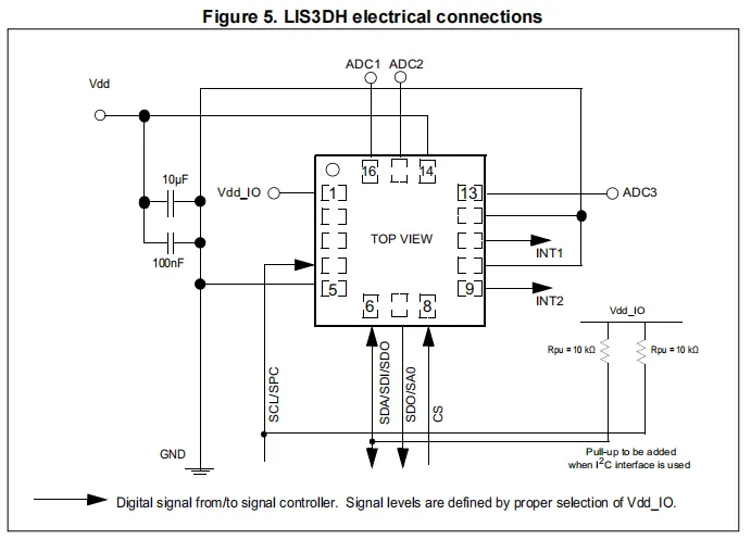
LIS3DH typical electrical connection diagram shows the power supply filtering circuit (10μF + 100nF capacitors), I²C interface pull-up resistor configuration, interrupt outputs (INT1 / INT2) and ADC auxiliary inputs, and also marks the communication pins and address selection logic in I²C mode, providing a clear hardware reference for stably implementing the power supply and communication of LIS3DH.
2.6 Chip Configuration
None.
2.7 Communication Interfaces and Related Protocols
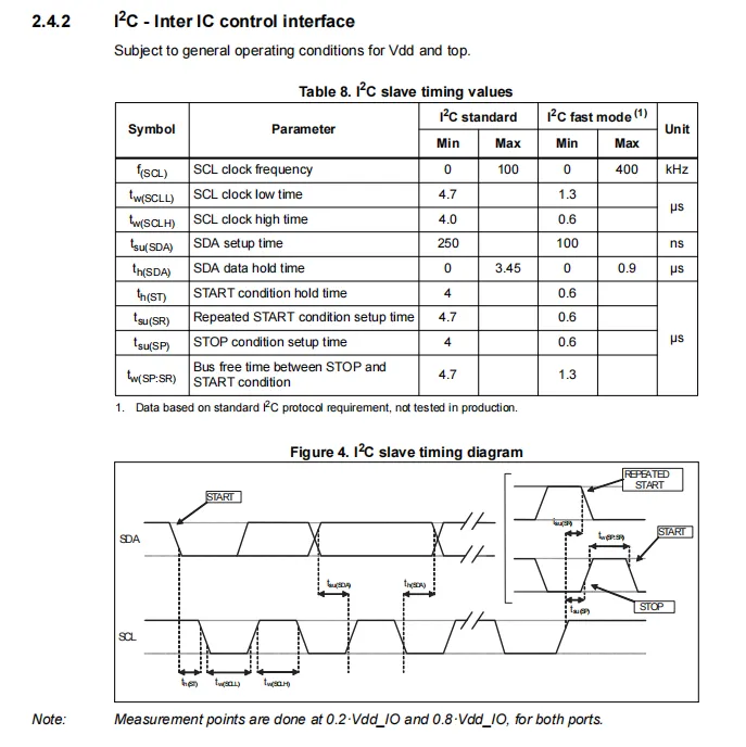
LIS3DH 's I²C interface timing parameter table and waveform diagram: supports both standard (100kHz) and fast (400kHz) I²C modes, and defines key parameters such as clock period, high/low level time, start/stop condition timing, and data setup/hold time, providing precise timing constraints and a protocol reference for stable I²C communication.
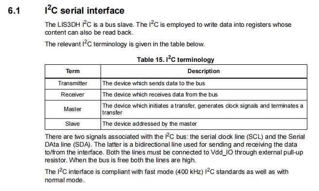
LIS3DH I²C interface overview: as an I²C slave device, it supports standard/fast (up to 400kHz) I²C communication, requires data read/write via SCL / SDA pins, the bus needs external pull-up resistors, and it is compatible with 3.3V level MCUs, providing stable digital communication and register operation capabilities for the system.
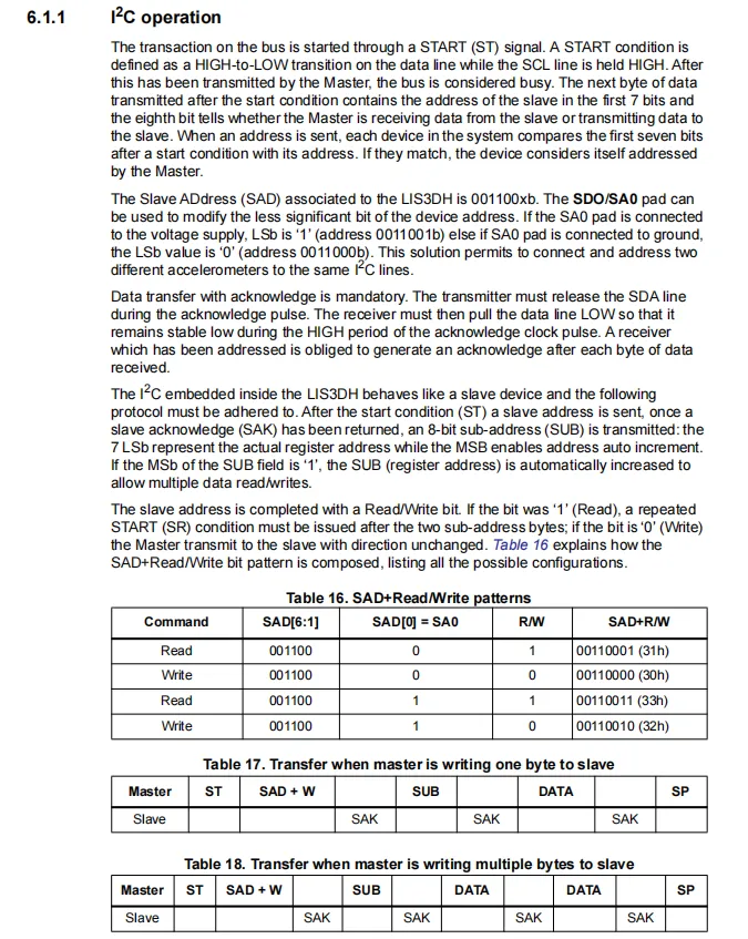
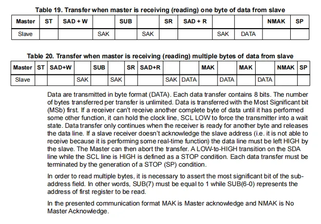
LIS3DH 's I ² C operation process introduces device address configuration ( 0x18 / 0x19 optional) , single-byte/multi-byte read and write timing , repeated START and address auto-increment functions, and provides a complete communication frame format and response mechanism, providing a clear protocol process reference for stable implementation of register configuration and acceleration data reading.
2.8 PCB Routing Notes
None.
III. Circuit Engineering
3.1 Circuit Source Engineering
To obtain the circuit source project, please follow the official account [Freak Embedded].
3.2 Module Usage Instructions
The schematic diagram of this module is shown below:
SCH_3-Axis Accelerometer Module Based on LIS3DH-V1.0.0_2026-03-27.pdf 2.2 MB
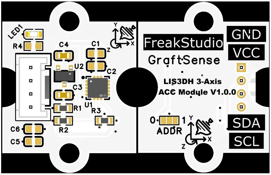
This module provides an I²C communication interface: it supports a maximum communication rate of 400kHz, and the device address can be flexibly configured via the ADDR dip switches (e. g., 0x18, 0x19). It is compatible with 3.3V logic level, and can stably implement three-axis acceleration data reading, register configuration, and interrupt status acquisition for special functions (tap / free fall). It is suitable for scenarios such as motion detection, posture recognition, and low-power portable devices, providing the system with high-precision inertial detection and interaction capabilities.
3.3 Application Experiment
Here, we use the GraftPort-RP2040 development board for testing, and the LIS3DH-based three-axis acceleration module uses the I2C interface to communicate with the main controller.
Here, we first use the HY2.0-4P connection cable to connect the module to the GraftPort-RP2040 development board's I2C0 interface:
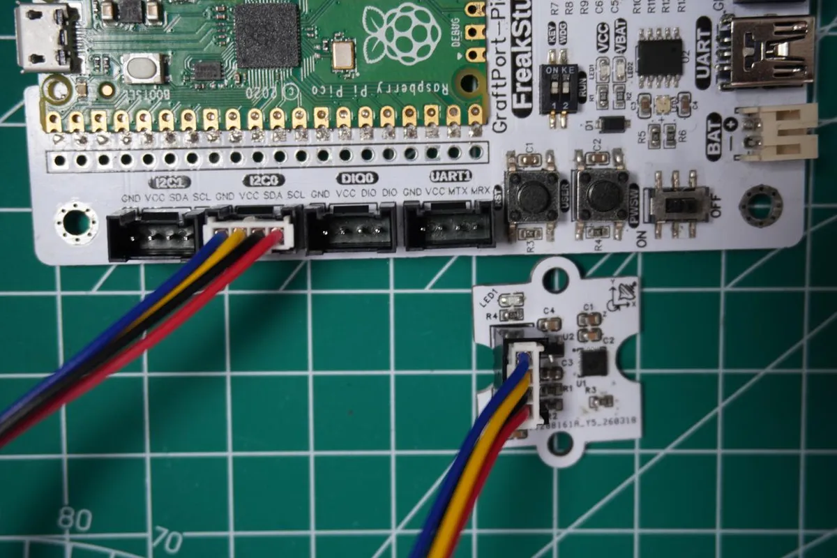
The module connections are shown in the following table:
Development Board Pins | Module Pins | Description |
Pin 4 |
|
|
Pin 5 |
|
|
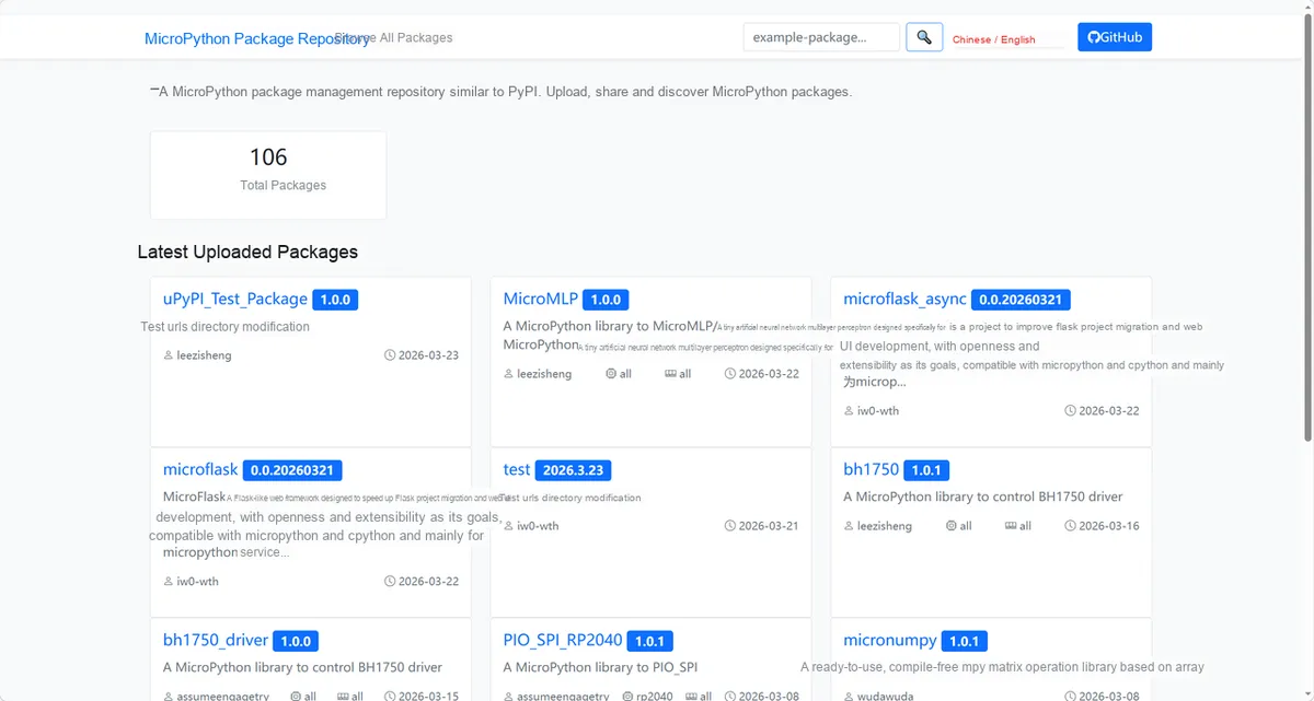
Here, we need to search for the relevant driver packages on uPyPI: https://upypi.net/zh/
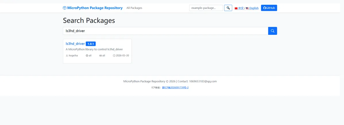
Enter ls3hd_driver to search, and the following will be displayed:
Click to copy the local installation command:
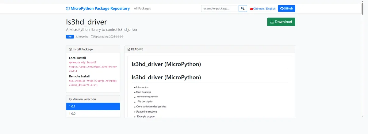
Import the module driver library code via the mip tool. Below are the usage commands for the mpremote tool:
mpremote mip install https://upypi.net/pkgs/ls3hd_driver/1.0.0Import the 3-axis acceleration module based on LIS3DH - MicroPython driver code, then copy the following main.py code into our project:
# Python env   : MicroPython v1.23.0
# -*- coding: utf-8 -*-
# @Time    : 2026/3/13 7:30 PM
# @Author  : Embedded Developer
# @File    : main.py
# @Description : LIS3DH accelerometer test: read acceleration data and convert it to pitch and roll angles

# ======================================== Import Modules =========================================

# Import the LIS3DH sensor driver module
import lis3dh

# Import the time module for delays and timestamps
import time

# Import the math module for angle calculation
import math

# Import the Pin and I2C modules for hardware communication
from machine import Pin, I2C

# ======================================== Global Variables ============================================

# Define the I2C SCL pin number
I2C_SCL_PIN = 5
# Define the I2C SDA pin number
I2C_SDA_PIN = 4
# Define the I2C communication frequency
I2C_FREQ = 400000
# Define the target I2C address of the LIS3DH sensor
TARGET_SENSOR_ADDR = 0x19

# Timestamp of the last angle conversion
last_convert_time = 0
# Time interval between angle conversions (ms)
convert_interval = 100
# Pitch angle (initial value)
pitch = 0
# Roll angle (initial value)
roll = 0

# ======================================== Functions ============================================


def convert_accell_rotation(vec):
    """
    Convert acceleration data to pitch and roll angles
    Args:
        vec: list/tuple containing the x, y, z acceleration values

    Returns:
        Tuple containing the currently calculated roll and pitch angles (unit: degrees)

    Notes:
        Recalculate the angles every 100 ms to reduce the calculation frequency; the angles are calculated with the arctangent function and converted to degrees
    ==========================================
    Convert acceleration data to Pitch and Roll angles
    Args:
        vec: List/tuple containing x, y, z three-axis acceleration values

    Returns:
        Tuple containing the currently calculated roll angle and pitch angle (unit: degrees)

    Notes:
        Recalculate angles every 100 milliseconds to reduce calculation frequency; angle calculation uses arctangent function and converts to degrees
    """
    x_Buff = vec[0]  # Extract the x-axis acceleration value
    y_Buff = vec[1]  # Extract the y-axis acceleration value
    z_Buff = vec[2]  # Extract the z-axis acceleration value

    global last_convert_time, convert_interval, roll, pitch

    # Check whether the angle recalculation interval has elapsed
    if last_convert_time < time.ticks_ms():
        last_convert_time = time.ticks_ms() + convert_interval

        # Calculate the roll angle (Roll), converted to degrees
        roll = math.atan2(y_Buff, z_Buff) * 57.3
        # Calculate the pitch angle (Pitch), converted to degrees
        pitch = math.atan2((-x_Buff), math.sqrt(y_Buff * y_Buff + z_Buff * z_Buff)) * 57.3

    # Return the current roll and pitch angles
    return (roll, pitch)


# ======================================== Custom Classes ============================================

# ======================================== Initialization configuration ===========================================

time.sleep(3)
print("FreakStudio: LIS3DH Accelerometer Test and Angle Calculation")

# Initialize the I2C bus with the specified pins and frequency
i2c_bus = I2C(0, scl=Pin(I2C_SCL_PIN), sda=Pin(I2C_SDA_PIN), freq=I2C_FREQ)
# Scan all devices on the I2C bus and get the list of device addresses
devices_list: list[int] = i2c_bus.scan()
# Print the I2C scan start message
print("START I2C SCANNER")
# Check whether any I2C device was found
if len(devices_list) == 0:
    # Print no-device message
    print("No i2c device !")
    # Raise an exception and terminate the program
    raise SystemExit("I2C scan found no devices, program exited")
else:
    # Print the number of devices found
    print("i2c devices found:", len(devices_list))
    # Initialize the sensor object to None
    imu = None
    # Iterate over the scanned I2C device addresses
    for device in devices_list:
        # Check whether the address matches the target sensor address
        if device == TARGET_SENSOR_ADDR:
            # Print the hexadecimal address of the matched sensor
            print("I2c hexadecimal address:", hex(device))
            try:
                # Initialize the LIS3DH sensor
                imu = lis3dh.LIS3DH_I2C(i2c=i2c_bus, address=TARGET_SENSOR_ADDR)
                # Print the sensor initialization success message
                print("Target sensor initialization successful")
                # Exit the loop after the target sensor is found
                break
            except Exception as e:
                # Print sensor initialization failure message
                print(f"Sensor Initialization failed: {e}")
                # Continue to the other addresses
                continue
    # Check whether the sensor was initialized successfully
    if imu is None:
        # Raise an exception indicating the sensor was not found
        raise Exception("No LIS3DH found")

# ========================================  Main Program  ============================================

# Check whether the sensor device is working properly
if imu.device_check():
    # Set the accelerometer range to 2G
    imu.range = lis3dh.RANGE_2_G

    # Read sensor data in an infinite loop
    while True:
        # Read the three-axis acceleration values and convert them to G values (divide by standard gravity)
        x, y, z = [value / lis3dh.STANDARD_GRAVITY for value in imu.acceleration]
        # Print the G values of the x, y, z axes
        print("x = %0.3f G, y = %0.3f G, z = %0.3f G" % (x, y, z))

        # Call the function to convert acceleration data to pitch and roll angles
        p, r = convert_accell_rotation(imu.acceleration)
        # Print the pitch and roll angles
        print("pitch = %0.2f, roll = %0.2f" % (p, r))

        # Delay 100 ms to balance responsiveness and resource usage
        time.sleep(0.1)
Burn the code, open the terminal, and the output is as follows:
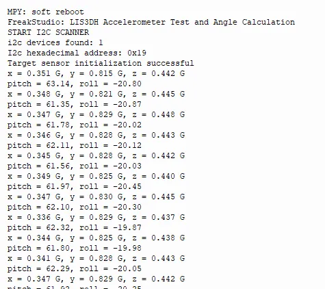
It can be seen that we can read the acceleration and convert it into the pitch angle and roll angle.
IV. Drivers
ls3hd_driver-1.0.1.zip 15 KB
5. BOM & Recommended Alternative Parts
None.
6. Revision History
Document Version | Date of Revision | Modifier | Modified Content |
v1.0 | 2026-03-27 | Ling Gaoxing | Initialize the document |
v1.0.1 | 2026-04-05 | Li Zisheng | The homepage photo has not been taken, the production files have not been exported yet, and all other items have been sorted out completely. |
v1.0.2 | 2026-04-21 | Li Zisheng | The production documents have not been exported yet, while all the others have been sorted out completely. |
v1.1 | 2026-04-23 | Xin Ruili | Create an open version of the document, based on the internal document version v1.0.2. |
VII. Relevant Materials
7.1 Chip Datasheet
LIS3DH.pdf 1.0 MB
7.2 Unique Icons for PCB Silk Screen