
Contents
- 1. Hardware Explanation
- 1.1 Overview of the Memory Structure of Single-Chip Microcomputers
- 1.2 Storage Structure of Raspberry Pi Pico
- 1.3 Memory Areas of MicroPython
- 1.4 File System in MicroPython
- 2. Software Control Method
- 2.1 os Module
- 2.2 vfs Virtual File Module
- 2.3 Block Device Abstract Class
- 3. Application Examples
- 3.1 File Read and Write Operations
- 3.2 Custom Logging Function
- 3.3 Implementation of the Simple Block Device Class
- 3.4 SD Card Mounting File System
- 3.5 External EEPROM Mounted File System
- References
- Addendum: closure
- Version Record
1. Hardware Explanation
In previous lessons, we have written several MicroPython programs running on the Raspberry Pi Pico development board, and uploaded the written code to the development board (i. e., programmed the board) using the MicroPython plugin for PyCharm. After the code is uploaded, the MicroPython VM will compile it into bytecode, and the interpreter of the VM will interpret the bytecode line by line, convert it into low-level instructions, and interact with the hardware resources of the MCU.
So here comes the question: where exactly are these codes stored in the MCU, and how are they executed? We need to understand the relationship between the program and the MCU, and here we will first explain the knowledge points related to program storage.
1.1 Overview of the Memory Structure of Single-Chip Microcomputers
In a microcontroller, the storage space used to store program code and runtime data is referred to as memory. From the perspective of whether it is directly connected to the CPU, the memory of a microcontroller can be divided into the following two types:
- Main Memory refers to the memory that the CPU can access quickly and directly, which is mainly used to store the program code and data currently being executed. Typical main memory includes ROM (Read-Only Memory) and RAM (Random Access Memory); both ROM and RAM serve the primary function of storing programs and data, ROM usually stores fixed program code, while RAM is used to store runtime data and variable programs.
- External Memory generally refers to storage devices that are not directly connected to the CPU, such as data storage accessed via USB, serial ports or parallel interfaces, which are mainly used to store program code or data that has not yet been executed. When needed, the data in external memory must first be loaded into main memory before the CPU can process it.
1.1.1 Classification and Characteristics of Main Memory
Main memory can be divided into the following parts:
- Program Memory (ROM): Stores the fixed program instructions, from which the microcontroller reads and executes the program once powered on. Most microcontrollers adopt Flash memory, which features erasability and re-writability to allow repeated program updates; its common capacity ranges from several KB to hundreds of KB, and some high-end microcontrollers even reach several MB.
- Data Memory (RAM): It stores temporary data and variables during program operation. In microcontrollers, static SRAM is often used to hold global variables, local variables and intermediate data. SRAM features fast read/write speed but data will be lost after power-off. The common RAM capacity of MCUs ranges from several hundred bytes to several hundred KB.
- Special Function Register (SFR): stores the status information that controls the operation of the microcontroller, especially the configurations related to peripherals and the core, including the Program Counter (PC), Stack Pointer (SP) and peripheral control registers
- General Purpose Register Set (GPR): These registers are used to store temporary data and operation results, serving as a bridge for data interaction between the CPU and memory
1.1.1.1 Introduction to ROM (Read-Only Memory)
ROM (Read-Only Memory) is a type of non-volatile memory that plays a crucial role in computers and embedded systems. ROM is characterized by data being written during memory manufacturing or initial programming, after which it can typically only be read and cannot be easily modified. The primary function of ROM is to store the firmware or programs required for system startup, ensuring that devices retain important data even after power is cut off.
The most common use of ROM is to store the firmware programs required when a device starts up, such as the BIOS of a computer or the boot program of an embedded device. Firmware is a set of instructions executed before the device runs, which is used to initialize hardware and load the operating system or other software; in embedded systems, ROM is often used to store the operating system or control code.
The original type of ROM is Mask ROM, whose data is directly written via a physical mask during the chip manufacturing process and cannot be modified after leaving the factory. Therefore, once the program changes, the entire chip has to be remanufactured. Later, there emerged another type of ROM that allows users to perform one-time programming with a dedicated device after the device leaves the factory — PROM, short for Programmable Read-Only Memory. Since it can only be programmed once, the chip has to be replaced once there is a writing error or a need to update the content. PROM is commonly used for testing during development and in low-volume production applications.
At present, the erasable and reprogrammable ROMs commonly used in embedded development fall into two categories:
- EEPROM (Electrically Erasable Programmable Read-Only Memory): It allows users to selectively erase and modify data in memory cells without erasing the entire chip, making it suitable for configuration data that needs to be retained but updated occasionally.
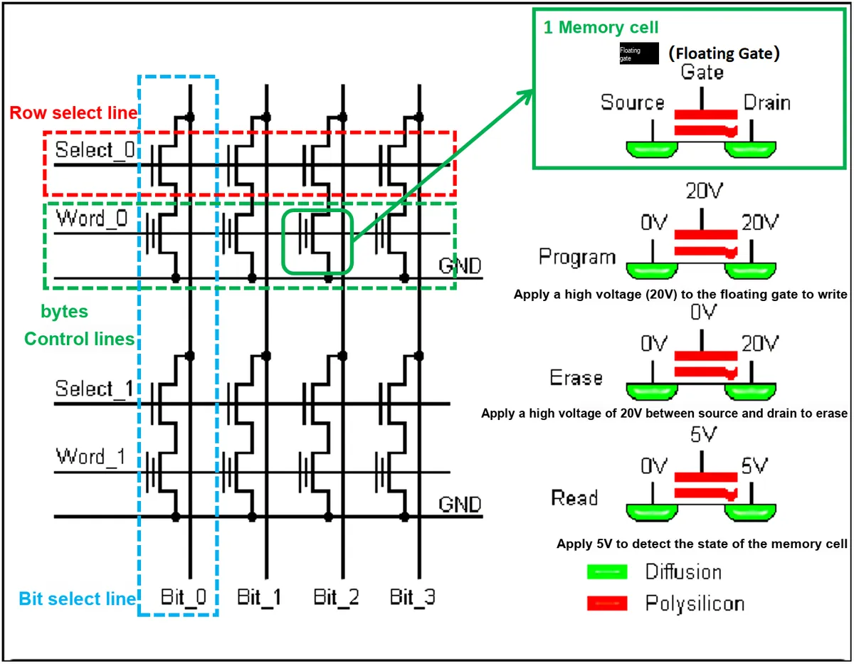
Structural diagram of the EEPROM memory cell array: we can use the Select_x row select lines and Word_x word select lines to select different memory cells, each of which corresponds to a transistor and stores 1 bit of data. A memory cell maintains its data state by storing electrons on the floating gate, and different operations such as writing, erasing and reading a byte can be performed by inputting different voltages through the byte operation lines. EEPROM supports byte-wise erasure or page-wise erasure (typically each page contains multiple bytes, and the specific size depends on the design of the EEPROM), allowing users to erase a single byte or an entire page of data. Write operations are usually performed on a byte-by-byte basis, meaning 1 byte of data can be written at a time. Write operations are generally slower than read operations and have a certain impact on the lifespan of the EEPROM (a typical EEPROM can withstand approximately 100,000 to 1,000,000 program-erase cycles). In addition, each write operation requires a certain amount of time (usually on the order of milliseconds), and after the write operation is completed, the chip enters a write delay state and cannot perform new operations.
- Flash Memory: Flash memory is a type of ROM based on EEPROM technology, which enables fast erasure and reprogramming of large blocks of data. It features high-density storage, fast erasing and writing speeds, and supports dynamic data modification during operation. It can function not only as a storage device (such as SSDs and USB flash drives) but also as program memory in embedded devices.
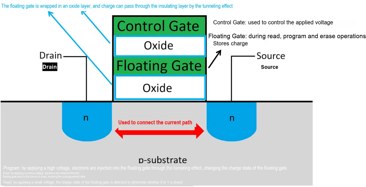
The core memory cell of Flash Memory is the floating gate transistor, whose operating principle is similar to that of EEPROM. Flash memory is typically erased in units called "blocks" or "sectors", with the size of a block or sector generally ranging from several kilobytes to several megabytes. A flash memory must undergo an erase operation before data can be written to it, and writing to flash is usually performed in units of "pages", which can range in size from several hundred bytes to several kilobytes (writing is also commonly referred to as "programming"). Flash memory has a limited number of program-erase cycles, with a typical lifespan ranging from 10,000 to 100,000 cycles. Erasing a single block takes several to tens of milliseconds, while a write operation typically takes several hundred microseconds to several milliseconds. Based on storage architecture, flash memory can be categorized into the following two types:
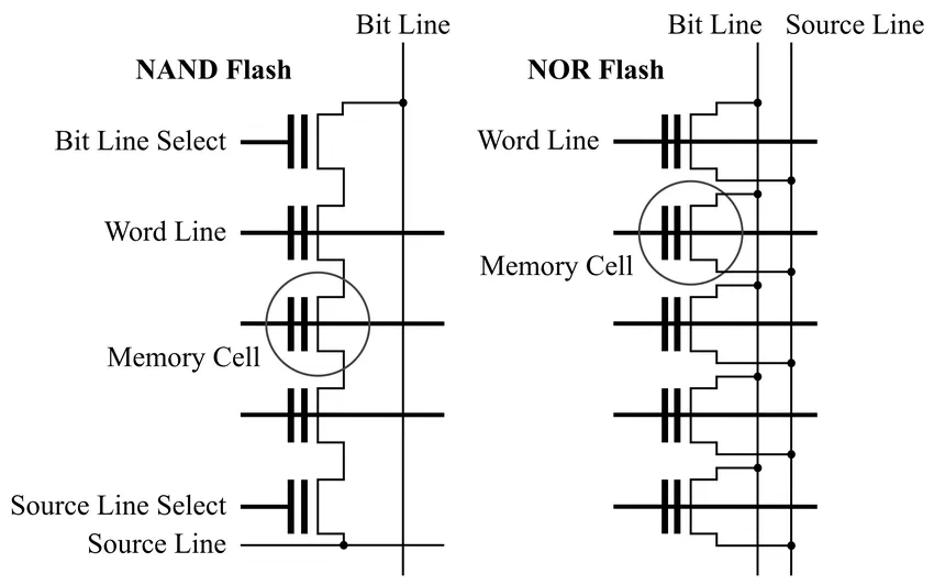
The memory cells in NAND Flash are connected in series, with multiple cells sharing the same Bit Line; in contrast, NOR Flash does not have a separate bit line selection circuit, and instead each memory cell is directly connected to the bit line and the source line, which enables more direct access to each cell. - NOR Flash: It adopts a linear addressing architecture, with memory cells addressed in bytes, similar to traditional RAM. Each byte of the memory cells has an independent address, supporting direct and random read operations, and data can be accessed byte by byte just like reading RAM. Thanks to its linear addressing structure, it enables Execute In Place (XIP) for direct code execution, so it is commonly used in scenarios requiring high read performance such as firmware and program code storage.NOR Flash features fast read speeds but slow write and erase operations. Limited by its architectural design, it has a low storage density, is typically used for small-capacity storage (ranging from several megabytes to dozens of megabytes), and comes with a large cell area, leading to high manufacturing costs.
- NAND Flash: It adopts a matrix addressing architecture, with data organized in units of pages. Memory cells are arranged in the form of pages and blocks: read and write operations are usually performed in page units, while erase operations are carried out in block units. Unlike NOR Flash, it cannot read byte data randomly, but performs sequential access, and operates on data in relatively large blocks.NAND Flash features extremely fast read and write speeds during sequential reading and large-block data operations, yet it has relatively slow random read speeds. With a higher storage density, it is suitable for large-capacity storage (ranging from several gigabytes to several terabytes) and is commonly used in large-capacity storage devices such as solid-state drives (SSDs) and USB drives.
The paging mechanism in EEPROM and the sector management in Flash both relate to the segmented management of storage media, yet there are still certain differences between them:
- Write Mode: EEPROM supports byte-by-byte writing in pages, and usually a single byte can be updated without erasure. In contrast, Flash can only write data in units of sectors, and the entire sector must be erased before writing.
- Storage Structure: EEPROM usually consists of multiple consecutive pages, each of which can store a fixed amount of data (e. g., 64 bytes); the size of a sector in Flash may be relatively large (e. g., 4KB, 16KB, etc.), and each sector typically contains multiple pages.
1.1.1.2 Introduction to RAM (Random Access Memory)
Random Access Memory (RAM) is a crucial storage medium in computers and other devices, which allows data to be read from and written to in any order. Its primary function is to provide fast-access data storage for the processor, supporting the operation of computer programs and the task scheduling of the operating system. However, it is a volatile memory, meaning that all data stored in RAM will be lost once the device is powered off.
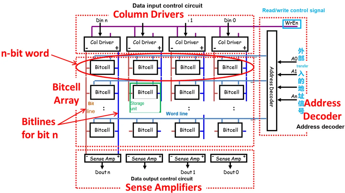
According to their operating principles, RAM can be divided into two types:
- DRAM (Dynamic Random Access Memory): Each memory cell of DRAM consists of a capacitor and a transistor. The capacitor is used to store electric charge: a fully charged capacitor represents "1", while a discharged capacitor represents "0"; the transistor acts as a switch to control the charging and discharging of the capacitor.The memory cells of DRAM are arranged in a two-dimensional matrix, with capacitors and transistors laid out in rows (wordlines) and columns (bitlines). After a memory cell is selected via the wordline and bitline, we can inject charge into the capacitor through the transistor (to write a "1") or discharge it (to write a "0") to complete a data write operation. When reading data, the state of the charge in the capacitor is likewise read through the transistor. It should be noted that the charge in the capacitor is consumed during the read process, so a refresh operation must be performed immediately after reading.
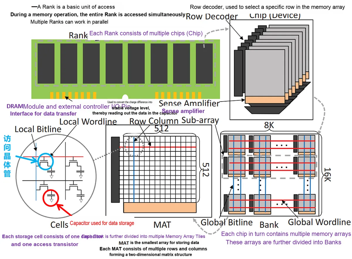
Simplified schematic diagram of DRAM structure: DRAM stores data via capacitors and relies on access transistors to perform data read and write operations. Its structure consists of multiple hierarchies, including Rank, Bank, MAT, etc., each of which is connected through local and global bit lines and word lines; during data reading, the row decoder activates a specific row, and the sense amplifier amplifies the charge difference in the capacitor to determine the stored binary value. Here, since capacitors leak charge over time, their charge must be refreshed periodically to prevent data loss — this is why DRAM is called "dynamic". We typically need to perform a refresh every few milliseconds; each refresh cycle reads the data from the memory cell and rewrites it to maintain data integrity.
- SRAM (Static Random Access Memory): Each memory cell of SRAM consists of six transistors, including two cross-coupled inverters for holding data (1 or 0) and two access transistors for controlling data read and write operations. Multiple memory cells are arranged in a two-dimensional matrix. Unlike DRAM, stable feedback is formed between the cross-coupled inverters responsible for data storage, eliminating the need for refresh operations.
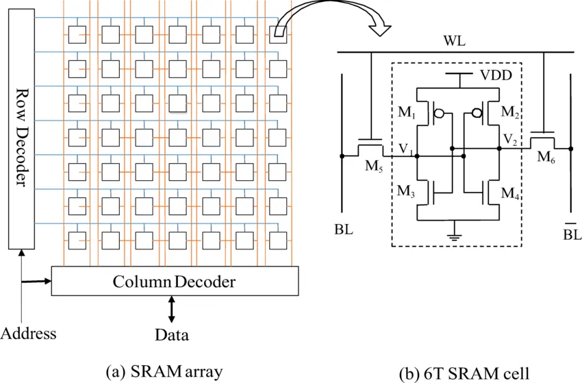
Since no refresh operation is required, SRAM has a much faster read and write speed than DRAM, making it suitable for scenarios with high speed requirements; however, as each memory cell consists of 6 transistors, SRAM has a significantly lower storage density than DRAM, and the cost per bit of stored data is higher than that of DRAM.
1.1.2 Classification and Characteristics of External Memory
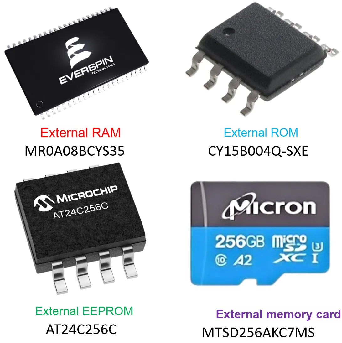
Common external memory includes external RAM, external ROM, external EEPROM and memory cards, as shown below:
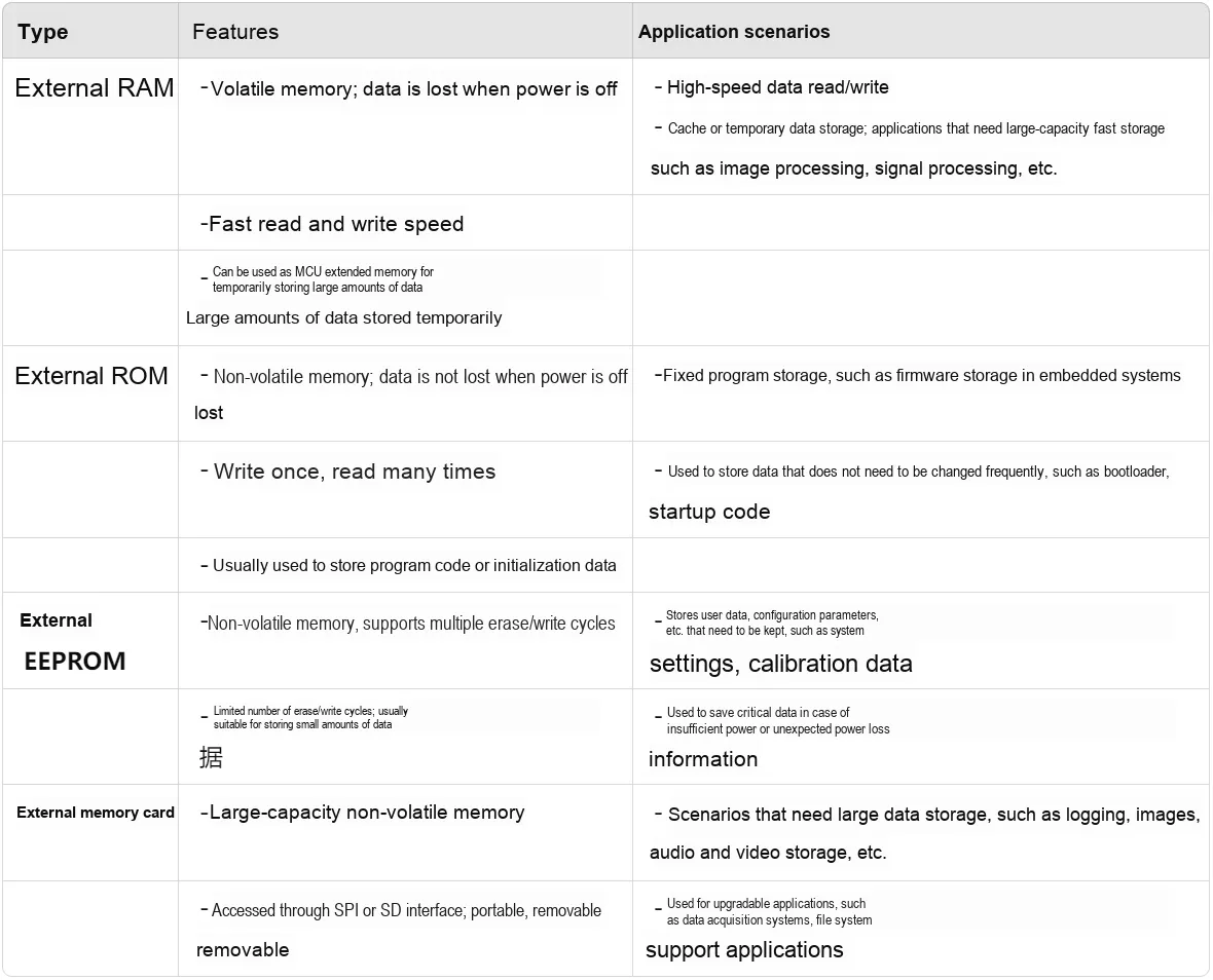
Different types of external memory each have their own characteristics and application scenarios:
1.1.3 Address Space and Bus Architecture
Address space refers to the range of all memory that an MCU can directly access. Each memory location has a unique address, which is usually represented in hexadecimal format. For example, the RP2040 MCU onboard the Raspberry Pi Pico is a 32-bit microcontroller, so its address space is 32 bits wide, capable of representing 2^32 addresses, which amounts to 4,294,967,296 bytes (approximately 4GB) of space, ranging from 0x00000000 to 0xFFFFFFFF.
Here, the 4GB address space is divided into multiple functional regions, including ROM, SRAM, peripherals, XIP (Execute In Place), etc. The addresses in these regions are mapped to different storage and peripherals, making it convenient for developers to directly operate hardware resources, as shown in the following figure:
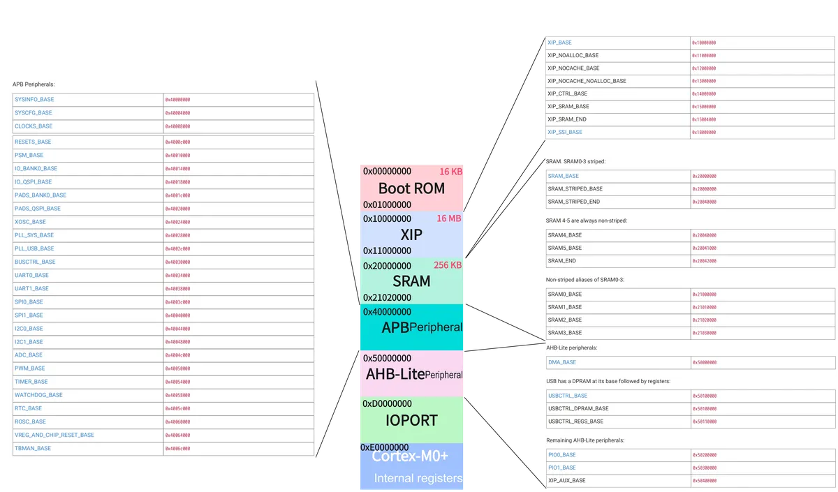
It mainly consists of the following parts:
- Boot ROM (Read-Only Memory): When the system is powered on or reset, the RP2040 will first execute the boot code from the Boot ROM, which is responsible for initializing the hardware and booting the user code to run.
- XIP (eXecute In Place register): The XIP region maps the external QSPI Flash memory for storing user code and data. The XIP technology allows the RP2040 to directly read and execute code from the Flash without copying the code to RAM, and the RP2040 communicates with the external Flash via the QSPI bus.
- SRAM (Static Random Access Memory): used to store temporary data, stack, etc. during program operation
- APB Peripherals (Low-speed Peripheral) Bus: It is used to connect some low-speed devices, such as GPIO control, timers, ADC, etc. APB peripherals are generally applied to peripherals with lower bandwidth, and their access method is similar to that of AHB peripherals, which directly controls the hardware by accessing the address registers.
- AHB-Lite Peripherals (high-speed peripheral) bus: It contains the register mapping of high-speed peripherals, such as DMA controllers, USB controllers, and PIO (Programmable Input/Output), which handle data transmission with relatively high throughput.
- IOPORT (Input/Output Port Register): This region contains SIO (Single-cycle Input/Output) registers, which enable rapid control and operation of GPIO pins and other simple peripherals.
- Cortex-M0+ Internal Registers: This area contains the internal registers of the ARM Cortex-M0+ core, including the interrupt controller, System Timer (SysTick), debug interface, etc. These registers control the core functions of the microcontroller, such as interrupt processing, system Time Management, and so on
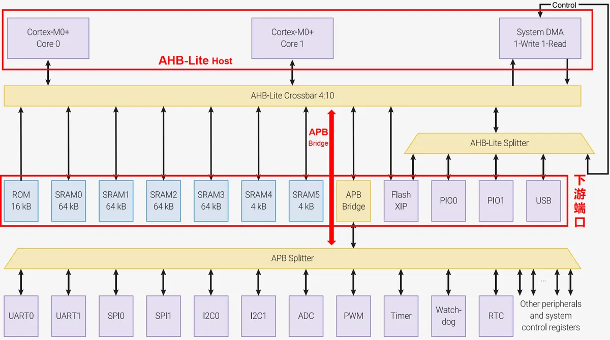
Here, the APB and AHB-Lite buses serve as communication channels for connecting the CPU, memory, and peripherals (such as UART, SPI, I2C, etc.) to transmit data, addresses, and control signals. Through these buses, the CPU can access the addresses on the buses, control these peripherals, and read their statuses.
1.2 Storage Structure of Raspberry Pi Pico
Here, we first clarify several core concepts of "mapping"(which forms the foundation of memory access), before explaining the address mapping tables for memory and SRAM. For the resources inside a chip (including memory, registers, and peripherals) to be accessible, they must first be assigned unique "house numbers" — this is precisely the essence of "mapping":
- Address mapping: the process of assigning a unique "digital house number"(i. e., system address) to every resource on the chip. For example, the house number for SRAM starts at 0x20000000, while that for ROM starts at 0x00000000. The core and DMA can precisely locate the resource to be accessed via this "house number", which essentially acts as a lookup table mapping resources to their corresponding house numbers.
- Register mapping: A subset of address mapping, which assigns house numbers to the registers (small memory units for storing configurations and statuses) inside a chip. For example, "0x40008000 corresponds to the baud rate register of the UART" — software can configure the UART by writing to this address, which is equivalent to a "correspondence table between register functions and their assigned addresses".
- Remapping: refers to "reassigning port numbers" — for example, if port number A originally corresponds to memory, after remapping, port number A can correspond to a peripheral, which enables flexible adjustment of resource access addresses to adapt to different scenarios.
For knowledge related to address mapping, register mapping, remapping and other related contents, please refer to the following link:
Fundamentals of STM32 Register Version — Memory Mapping:
https://developer.aliyun.com/article/935522
[Experience Sharing] STM32 Getting Started Series - STM32 Peripheral Address Mapping
https://shequ.stmicroelectronics.cn/thread-635602-1-1.html
Microcontroller Memory and Memory Mapping (Local Address, Logical Address, Global Address)
https://blog.csdn.net/u014157109/article/details/120370973
Memory access is entirely based on address mapping. The memory structure of the Raspberry Pi Pico consists of 16 kB of ROM with fixed content and 264 kB of SRAM that supports parallel access. The SRAM adopts a design of multiple physical memory blocks to improve access efficiency, and external Flash memory (2 MB in size) is accessed via the QSPI interface.
1.2.1 ROM
16 kB read-only memory (ROM) at address 0x00000000. The contents of the ROM are fixed once the chip is manufactured. It contains:
- Initialize the boot routine
- Flash Boot Sequence
- Flash Programming Routine
- USB mass storage device supporting UF2
- Utility libraries, such as fast floating-point arithmetic
The ROM bootloader can be downloaded at this link: https://github.com/raspberrypi/pico-bootrom
This ROM supports single-cycle read-only bus access and is connected to a dedicated AHB-Lite arbiter, enabling simultaneous access with other memory devices. Any attempt to write to the ROM will have no effect and will not trigger a bus fault.
1.2.2 SRAM
The on-chip SRAM totals 264 kB, which is physically divided into six banks, a design that significantly boosts the memory bandwidth for multiple bus masters — this allows multiple bus masters (such as Core0, Core1, and DMA) to access different banks simultaneously, eliminating resource contention — while software can treat it as a single 264 kB memory region for read and write operations (physical access to individual banks is implemented via address mapping).
There are no restrictions on the content stored in each bank: it can hold applications, data buffers, etc.
A bank can be divided into four 16k×32-bit blocks (each of 64 kB) and two 1k×32-bit blocks (each of 4 kB).
Each SRAM bank can be accessed via a dedicated AHB-Lite arbiter, which means different bus masters can access separate SRAM banks in parallel, enabling up to four 32-bit SRAM accesses (one per master) per system clock cycle.
In the memory mapping, the start address of the SRAM is 0x20000000, and the base address of each specific bank is as follows:
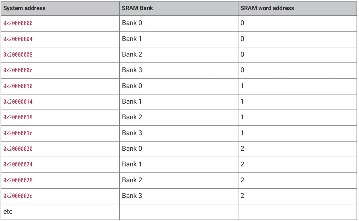
We can see that this mapping table contains the following information:
- System address (system address): The "house number" of SRAM, through which the core/DMA accesses the SRAM (for example, 0x20000000 is the first house number of SRAM);
- SRAM Bank (SRAM Physical Partition): The actual physical memory block of SRAM (Bank0 to Bank3 are shown here, and there are additionally 2 small 4kB banks);
- SRAM word address: A "word" consists of 32 bits (equivalent to 4 bytes), and this address serves as the offset house number within the corresponding bank (for example, "word address 0" refers to the first 32-bit data entry in the bank).
Here, the SRAM memory address mapping of the RP2040 adopts a striped storage mechanism to improve parallel access performance, and memory addresses are distributed across four memory blocks in units of words: as the system address increments by 4 (since 32 bits = 4 bytes), it will polling different banks in the order of "Bank0 → Bank1 → Bank2 → Bank3", then return to Bank0 to increment the "word address" — for example:
- 0x20000000 (house number) → Bank0, word address 0;
- 0x20000004 (+ 4) → Bank1, word address 0;
- 0x20000010 (add another 4) → return to Bank0, word address 1.
The advantage of this mapping is that when multiple modules access different system addresses simultaneously, they are actually accessing different physical banks. For example, when Core0 accesses 0x20000000 (Bank0) and DMA accesses 0x20000004 (Bank1), the two will not interfere with each other, realizing "parallel access" and greatly improving the read and write speed of SRAM.
Since consecutive bytes in the system address space are allocated to different memory blocks, multiple memory accesses can be performed simultaneously, which improves memory bandwidth and overall performance, reduces conflicts between different memory access requests, and thus enhances memory access efficiency.
Striped storage mechanism
The core concept of striping storage mechanism is to evenly distribute data across multiple storage blocks to achieve more efficient parallel access. Specifically, data is split into fixed-size blocks (usually bytes or words), which are allocated to different storage units (such as memory blocks, disk stripes, etc.) according to a certain rule.
Striped storage enables simultaneous access to multiple storage blocks, thereby improving overall bandwidth and system performance: for instance, in memory, striping allows multiple memory access requests to be processed concurrently, boosting data transfer speeds. Striped storage is also applied in disk arrays; in disk array systems such as RAID 0, striping is used to distribute data across multiple hard drives to enhance the read and write throughput of the disk.
In addition, the two 4kB regions located at 0x20040000 and 0x20041000 are directly mapped to two small 4kB memory blocks. These regions can be dedicated to per-core operations, such as stacks or frequently executed code, to ensure that no processor waiting occurs when accessing these regions.
In addition to the on-chip SRAM, there are two dedicated RAM blocks that can be used in certain scenarios:
- Flash XIP Cache: If the Flash XIP cache is disabled, this cache can be used as 16kB of memory with a start address of 0x15000000
- USB Data DPRAM: If USB is not in use, this 4kB memory region can also be used as general-purpose memory, with a starting address of 0x50100000
Layman's Explanation of Dedicated RAM Blocks
Simply put, they are "part-time RAM": they have their own dedicated primary functions at ordinary times, and can "fill in" as regular memory when not in use, acting as a "backup storage area" within the chip.
- First, let’s clarify the "core responsibilities" of the two dedicated RAMs:
- Flash XIP cache: As mentioned earlier, Flash is an "external storage" device, and its speed is much slower than that of on-chip SRAM. The XIP (Execute In Place) function temporarily stores frequently used code and data from the Flash in a high-speed RAM (cache) — this way, when the kernel accesses these contents, it can directly read from the cache instead of waiting for the slow Flash, which is the core function of a cache.
- USB data DPRAM: DPRAM is Dual-Port RAM, the dedicated data buffer of the USB module — when USB transfers data, it first stores the data in this RAM, which is then processed by the core or DMA; this is its core function.
- There are two scenarios where memory can be "repurposed as regular RAM": These two RAM modules are normally occupied by their intended functions, but when the corresponding features are not in use, they can be utilized as standard memory (the address mapping also assigns them "spare address entries" for this purpose):
- Disable Flash XIP cache to convert it to regular RAM: If you do not need the XIP acceleration feature for Flash (for example, when the entire program is stored in on-chip SRAM), you can disable the XIP cache — this block of RAM originally dedicated to Flash acceleration will then be freed up. Its "alternate base address" is 0x15000000, which you can use to store regular programs and data, effectively adding an extra block of memory.
- When USB is not in use → USB DPRAM becomes general-purpose 4kB memory: If the project you are working on does not require USB functionality (e. g., a pure sensor acquisition device), the USB module will be left idle — its dedicated DPRAM (4kB) will also be freed up, with the corresponding "reserved memory address" being 0x50100000, and this 4kB RAM can then be used as general-purpose memory (e. g., for storing small data buffers or temporary variables).
Simply put, this is a "resource multiplexing" design for chips: the RAM dedicated to specific functions is opened up as general-purpose memory when the corresponding functions are idle, so that the limited storage resources can be utilized more flexibly.
1.2.3 External Flash
Here, we first introduce two key concepts:
- QSPI interface: a "high-speed data line" between the chip and external Flash (faster than ordinary SPI), which is responsible for the communication between the chip and the external Flash.
- XIP (Execute In Place): Literally meaning "execute in place" — there is no need to copy the program from the external Flash to the on-chip SRAM;the program can be run by directly accessing the external Flash, which is equivalent to using the external Flash as "extended memory" and saves SRAM space.
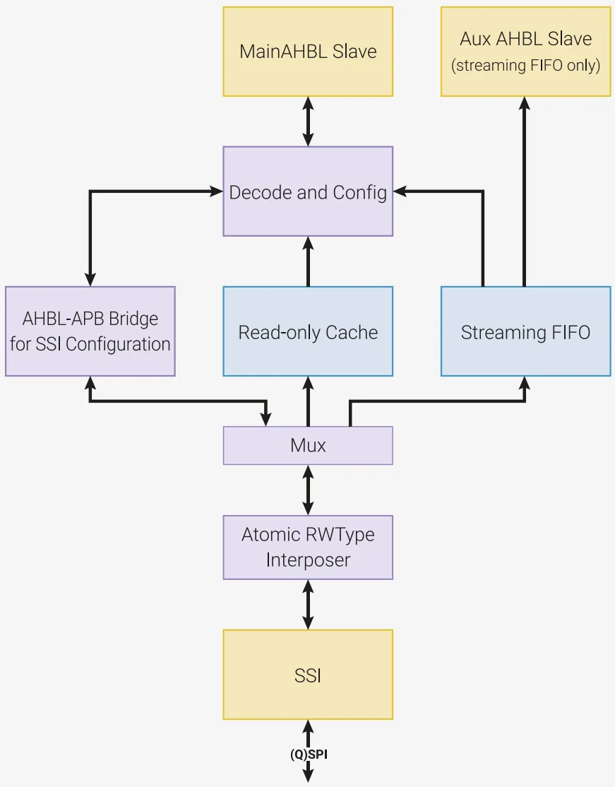
The flash management of the RP2040 microcontroller adopts the Execute-In-Place (XIP) mechanism, which achieves efficient flash access through four main components: the QSPI interface, XIP hardware, XIP cache, and Serial Flash Interface (SSI).
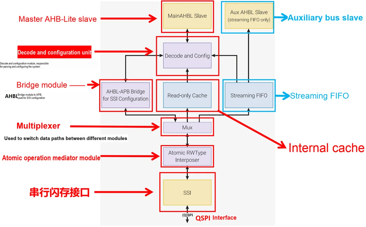
The core of the entire structure is to enable external Flash to be accessed in the same way as internal memory, accelerate the access speed with cache, and ensure stable communication:
- SSI Module: It directly connects to the QSPI interface, serving as the "physical layer" for communication with external Flash — it is responsible for transmitting and receiving QSPI signals, and is the component that actually transfers data with the external Flash.
- Atomic RWType Interposer (Atomic Operation Protector): It ensures that read and write operations to Flash are "completely uninterrupted"(for example, when reading a 32-bit data, the process will not be interrupted by other operations), so as to avoid data reading errors or writing disorder.
- Mux Multiplexer: It acts as a "data path switch", selecting whether to read data from Cache or directly from Flash, prioritizing Cache for faster speed.
- Read-only Cache: Since external Flash is slower than on-chip SRAM, the Cache stores frequently used content from the Flash (such as frequently executed program instructions) here; when the core accesses data, it first checks the Cache, and if the content exists, it reads directly without waiting for the slow Flash, greatly improving the speed of XIP.
- Streaming FIFO Continuous Data Buffer: When reading a large volume of consecutive data from Flash (such as a lengthy program segment or a large file), the data is first stored in this FIFO before being transferred to the kernel. This prevents "intermittent" data transmission and ensures smoother consecutive access.
- Decode and Config Address Resolution Configuration Unit:
- Parse the address sent by the kernel: determine which location in the external Flash this address corresponds to;
- Manage the configuration of the entire XIP hardware: such as enabling/disabling the Cache, setting the communication speed of QSPI, configuring the size of the FIFO, etc.
- Main AHBL Slave / Aux AHBL Slave: This XIP hardware is connected to the "interface" of the system bus (AHBL):
- Main interface: responsible for regular Flash access (such as reading scattered instructions/data);
- Aux Interface: exclusively responsible for high-speed continuous data transmission of Streaming FIFO, and is specifically designed for high-traffic scenarios.
- AHBL-APB Bridge for SSI Configuration: It serves as the configuration interface of the SSI. The core sets parameters for the SSI module via the APB bus (such as the clock frequency and transmission mode of QSPI), enabling the SSI to communicate and match with external Flash of different models.
The external Flash (with a maximum support of 16MB) can be accessed via the QSPI interface using execute-in-place (XIP) hardware. This allows the system to address and access the external flash just as it would access internal memory, without the need to first copy code into internal memory: accesses to the 16MB flash region starting at the address range 0x10000000 will be mapped to read operations on the external serial flash, with the results directly returned to the master device that initiated the request.
The workflow of the XIP subsystem is as follows:
- System Access Decoding: When the system performs memory accesses, these accesses are routed through the main AHB-Lite slave, and the accesses are decoded to determine whether they are XIP accesses, direct accesses to the SSI (Serial Peripheral Interface)(e. g., for configuration), or accesses to other hardware and control registers within the XIP subsystem
- XIP Access Processing :
- Cache lookup: For XIP access, the requested data is first looked up in the internal cache, which is used to accelerate access to recently accessed data. If the requested data is found in the cache (cache hit), the data is returned directly from the cache.
- Cache miss: If the requested data is not found in the cache (i. e., a cache miss occurs), an external serial access request will be generated, which is sent to the external flash memory via the SSI interface to obtain the required data
- Data storage and forwarding:
- Data Storage: Data retrieved from external flash memory is stored in the cache to enable faster data delivery for future accesses.
- Data forwarding: The acquired data is then forwarded to the system bus to fulfill the original access request. In this way, the XIP subsystem ensures that the accessed data is available on both the system bus and the processor.
1.2.3.1 XIP Cache Mechanism
XIP cache is an internal cache designed to accelerate access to external flash memory. It has a size of 16KB, adopts a two-way set-associative structure, and features a latency of 1 clock cycle per cache hit; this cache is exclusively used for accesses to XIP flash, and software does not need to account for cache consistency in most cases, with the exception of flash programming operations.
The cache is mapped to the 24-bit flash address space. In the system addresses of the RP2040, the upper 8 bits are used for segment decoding, and the remaining 24 bits are used for the flash address, so the maximum supported flash size is 16MB. The flash address space has multiple mirrors in the RP2040's address space, and each mirror has different cache behavior. The specific mirror addresses and their cache behaviors are as follows:
- 0x10…: XIP access, cache available, cache allocation (cacheable, allocating). This is a normal cache operation, where the cache loads data from the flash and updates itself upon a cache miss.
- 0x11…: XIP access, cache available, non-cache allocation (cacheable, non-allocating). It checks for cache hits but does not update the cache upon a miss.
- 0x12…: XIP access, non-cacheable, allocating. No cache hit check is performed; data is always read from flash and the cache is updated.
- 0x13…: XIP access, non-cacheable, non-allocating. Completely bypasses the cache and directly accesses the flash memory
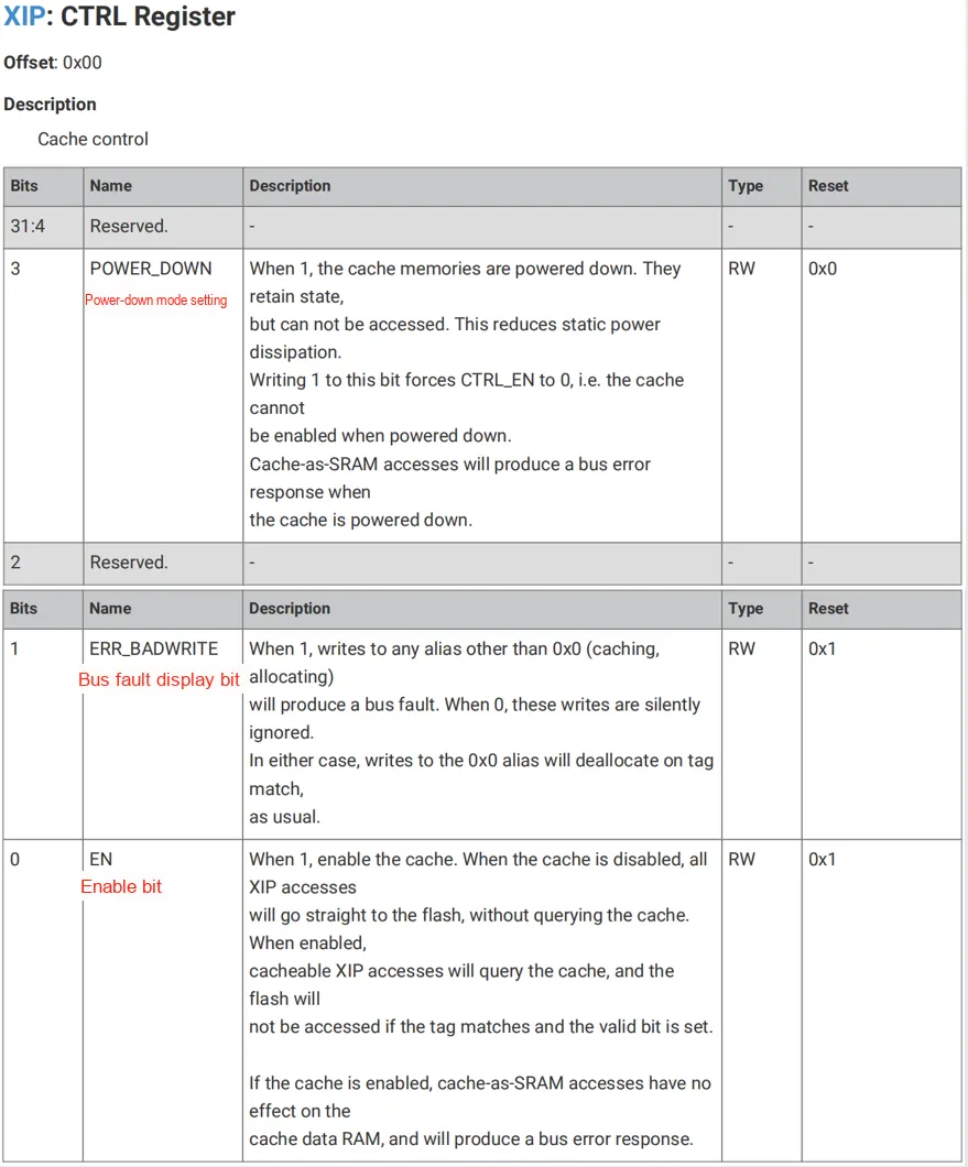
- 0x15…: Use the XIP cache as an SRAM region and mirror it throughout the entire segment. When the cache is disabled (by clearing the CTRL.EN register bit), this region behaves as an additional 16KB SRAM region, with read and write operations both taking 1 cycle, but consecutive write-read sequences will incur one wait state
By setting the CTRL.EN register bit, the cache can be disabled. When the cache is disabled, all XIP address mirrors from 0x10 to 0x13 will bypass the cache and directly access the flash memory, which will significantly affect the execution performance of XIP code.
1.2.3.2 XIP Cache Flush and Maintenance
When the software reprograms the flash memory content, it is necessary to clear the stale data and code in the cache to ensure that the system uses the latest data without restarting. In this case, the FLUSH register can be used to refresh the entire cache content.
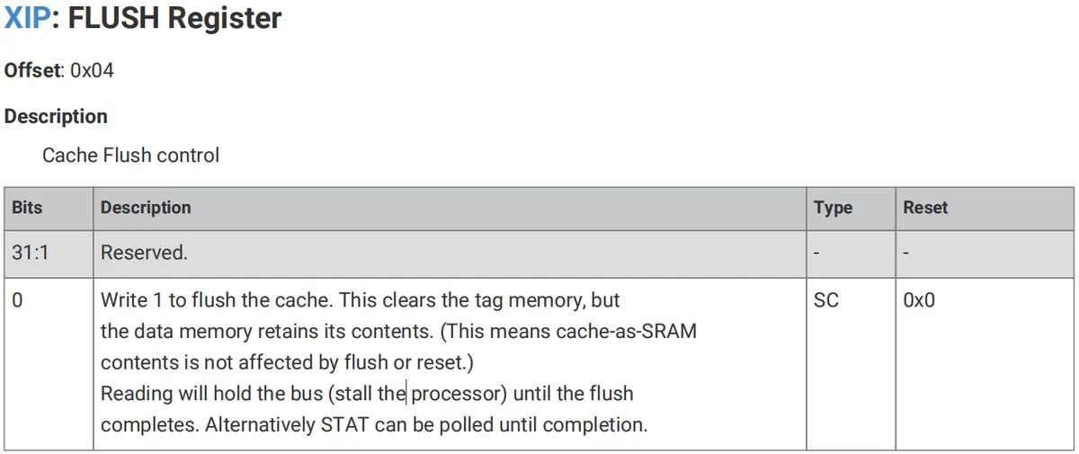
We can implement cache flushing by writing a 1 to the 0th data bit of the FLUSH register, and the cache flushing is accomplished by clearing the cache tag memory. Since the total cache size is 16KB, each line of the tag memory is 8 bytes, and there are 2 ways per set, the flushing process requires approximately 1024 clock cycles.
We can wait for the refresh operation to complete by reading the 0th data bit of the FLUSH register, which will block the processor until the refresh finishes; alternatively, we can check the refresh status by polling the STAT register.
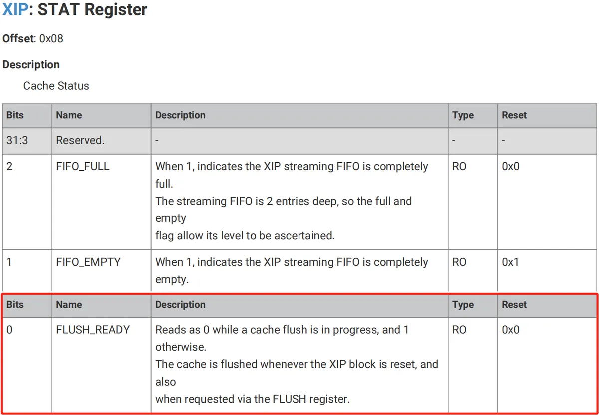
Here, accessing flash memory data during a cache flush is safe: if another master device accesses the flash memory data while a cache flush is in progress, those master devices will be blocked until the cache flush is completed, which ensures that no inconsistent data access occurs before the flush finishes.
It should be noted that when the XIP cache is used as a 16KB SRAM (with the mirror address being 0x15…), the cache will be directly used as memory and support both read and write operations. If the cache is flushed at this time, the data content in the cache will not be modified; however, if a write operation is performed on the address range where the cache acts as SRAM during the flushing process, data inconsistency or corruption may occur. To avoid data corruption, it is recommended to perform write operations on the cache used as SRAM only after the cache flushing operation is completed, which can be achieved by confirming that the cache flushing operation has been fully finished before executing the write operation.
Completing a full cache flush will significantly slow down the execution speed of subsequent code until the cache is "re-warmed" to restore normal performance. To avoid this performance penalty, an alternative approach is to only invalidate the cache contents for a specific address range.For example, when a sector of the flash memory is erased and reprogrammed, it is only necessary to ensure that the stale data of that sector in the cache is updated, rather than flushing the entire cache. In the RP2040, you can trigger the invalidation of a specified address range in the cache by writing data to the 0x10.. . mirror address. The 0x10.. . mirror address here refers to a special mapping of the cache, which supports partial invalidation of data within a specific address range:
- Lookup cache entries: When writing to the 0x10.. . mirror address, the cache checks for cache entries within this address range
- Delete entries: If matching cache entries are found, these entries will be deleted, the cached data will be marked as invalid, and when these addresses are accessed next time, the data will be reloaded from the data source (such as flash memory)
1.2.3.3 SSI Serial Flash Interface
SSI (Synchronous Serial Interface) is a critical peripheral in the RP2040 microcontroller, designed to handle serialized flash memory access. It supports various SPI (Serial Peripheral Interface) modes, including standard SPI, Dual SPI (DSPI), and Quad SPI (QSPI). SSI enables XIP (Execute-in-Place) access via multiple operating modes, ensuring compatibility with nearly all types of serial flash memory devices.
The maximum SPI clock frequency of the SSI is half of the system clock frequency. It supports inserting instruction prefixes or mode continuation bits during each XIP access, and also supports the standard FIFO (First-In, First-Out) SPI host mode, with DMA (Direct Memory Access) support provided at the same time, which makes it applicable to high-speed data transmission.
1.2.3.4 Flash Streaming and Auxiliary Bus Slave
In embedded systems, flash memory is typically much larger than static random access memory (SRAM). Therefore, when it is necessary to transfer a large amount of data from flash memory to RAM, adopting a streaming transmission approach is extremely useful. This operation allows DMA (Direct Memory Access) to stream data in the background, while the processor in the foreground continues to execute other tasks.
Standard XIP (Execute-in-Place) operations are not highly compatible with streaming transmission, because when the SSI (Serial Peripheral Interface) performs serial transmission, it will cause a relatively long bus delay for DMA. This delay may be acceptable for the processor, since the processor generally has no other valid operations to perform while waiting for instruction fetch, and code execution usually features a high cache hit rate.
However, for DMA, such delays will prevent other active DMA channels from continuing to operate, thereby reducing the overall DMA throughput, which calls for a solution to mitigate this impact.
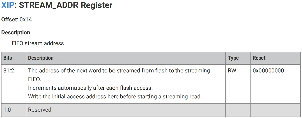
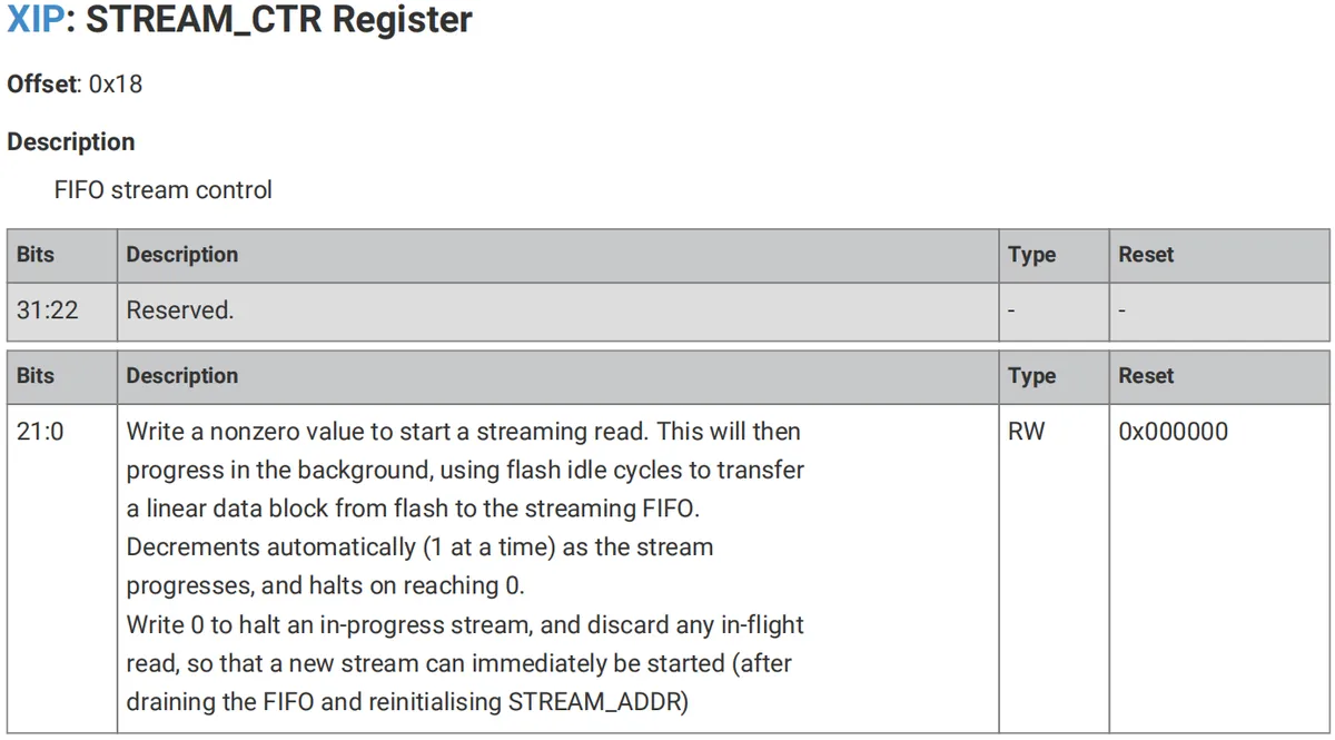
In the RP2040, STREAM_ADDR and STREAM_CTR registers are used to configure the continuous data reading from the flash and the subsequent data transfer to the memory, an operation referred to as streaming, whose primary purpose is to efficiently load large volumes of data from the external Flash into the SRAM memory:
- Using the
STREAM_ADDRregister, you can specify the starting address from which data is to be read from the flash memory:
- By using the
STREAM_CTRregister, you can start and stop streaming transmission.
The specific steps are as follows:
- Write a non-zero value: To start streaming: when a non-zero value is written to this field, the streaming operation will start running in the background, which utilizes the idle cycles of the flash memory to read data from the flash memory in the specified linear blocks and store the data into the streaming FIFO; this value will automatically decrement by 1 after each data transfer, and the streaming will stop automatically when the value decrements to 0.
- Write a value of zero: Stop the currently ongoing streaming transfer and discard any data that is in the process of being transmitted.
Once streaming is configured, the XIP (Execute-in-Place) subsystem automatically handles these data read operations in the background without requiring the CPU to wait. During the streaming process, the streaming hardware of the XIP subsystem performs data reading at a lower priority. This means that streaming operations will not preempt the processor's executing tasks or cause significant latency.
When code is executed from flash, cache misses may occur (meaning there is no data in the cache and it needs to be read from flash). Compared with regular XIP access, streaming hardware will experience a short Cool Down (seven clock cycles) after a cache miss to avoid causing additional latency when a cache miss occurs.
Streaming reads data from the flash memory and pushes it into a small FIFO buffer queue. When the data in the FIFO is ready, it generates a DREQ (Data Request) signal, which notifies the DMA controller that data can be read from the FIFO. The DMA controller is responsible for fetching the data from the FIFO and transferring it to the target memory or device. It should be noted that the DMA only reads the FIFO after the data is ready, so it will not be blocked by the flash reading process.
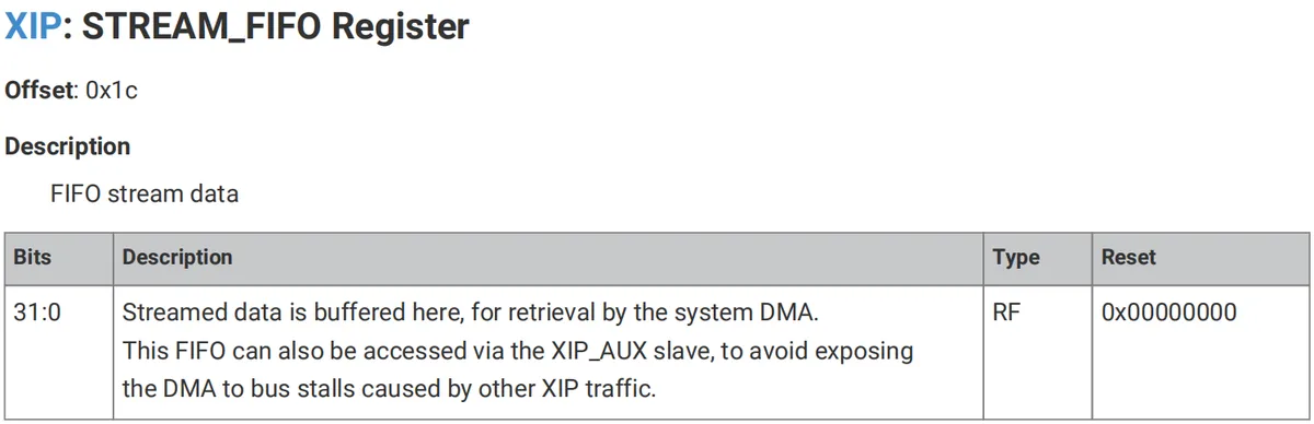
Although the data is already prepared and stored in the FIFO, if another system master (such as a CPU or an external device) is accessing the XIP flash and gets blocked due to a cache miss or other reasons, this may affect the operation of the DMA. To address this issue, the RP2040 utilizes an auxiliary bus slave, which is a simple bus interface exclusively designed for accessing the streaming FIFO; this slave device is connected to the FASTPERI arbiter, which serves native AHB-Lite peripherals that do not generate wait states.This way, the DMA will not encounter additional wait states or blocking when accessing the FIFO, since the accesses of the auxiliary bus slave will not be interfered with by other bus operations.
1.2.3.5 Performance Counters
The XIP (Execute-In-Place) subsystem of the RP2040 is equipped with two performance counters, which are used to monitor and analyze the performance of the cache. These counters can help developers understand the usage and efficiency of the cache, so as to optimize code and system design.
Both counters are 32 bits wide, which means the maximum value they can count up to is 0xFFFFFFFF (i. e., 4294967295); once this value is reached, the counter will wrap around (i. e., return to 0). Meanwhile, the value of the counter can be cleared by writing any arbitrary value, which is typically used to reset the counter to start a new counting cycle.
- Counter 1 - Total XIP Access Count: Counter 1 is used to track the total number of all access requests to XIP flash memory, and this counter increments by 1 for every access regardless of whether the access hits the cache or not.
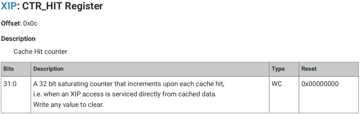
- Counter 2 - XIP Cache Hit Count: Counter 2 is used to track the number of cache hits among all XIP accesses, that is, this counter increments by 1 each time the requested data already exists in the cache.
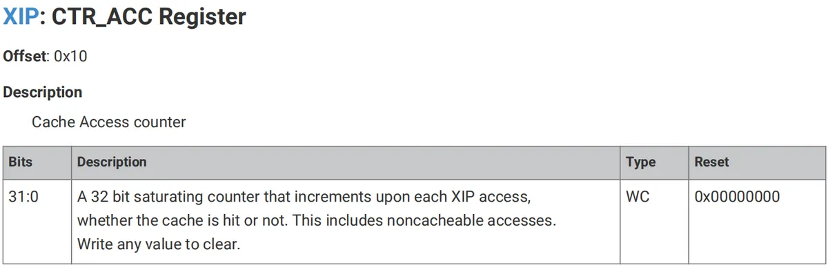
When used together, these two counters can provide useful performance data related to XIP operations. For example, by comparing the number of hits with the total number of accesses, the cache hit rate can be calculated, so as to understand the effectiveness of the cache and the room for optimization.
1.3 Memory Areas of MicroPython
When learning MicroPython, understanding its "memory regions" is equivalent to figuring out where our programs "reside" and in which "cabinet" different types of data are stored. Only by grasping the rules governing data storage can we avoid writing code that causes memory overflow or unexplained data errors, and also gain insight into the underlying logic of program execution.
First, let’s supplement two basic concepts that every beginner must know:
- Flash (flash memory): It can be understood as the "hard disk of a computer" — data will not be lost after power-off, its read and write speed is relatively slow, so it is suitable for storing long-term unchanging content. The firmware of MicroPython and the program code we write are both stored here.
- SRAM (Static Random Access Memory): It can be analogized to the "RAM stick of a computer" — it loses all stored data once powered off, but features extremely fast read and write speeds, making it ideal for storing frequently changing temporary data that programs need during operation.
The storage area distribution of MicroPython is similar to the memory model of traditional programming languages (C/C++), which is mainly divided into two major blocks: Flash and SRAM (Static Random Access Memory). Each block contains sub-areas with different functions, each performing its own duties:
- The content in Flash is just like a movie engraved on an optical disc: once finalized, it will not be modified arbitrarily, and the data will still be retained even after power-off, so it is mainly used to store "unchangeable content":
- Code Section: This area stores program code, namely bytecode or compiled machine code, as well as the underlying interpreter code; it remains unchanged at runtime, will not be modified, and is read-only in attribute;
- Read-Only Data Section: This area stores constant data, such as string literals (e. g.,
"hello MicroPython"), module-level constant variables (e. g.,MAX_NUM = 100defined at the start of a module). The data stored here will not be modified during program execution, is static content, and can be reused throughout the entire runtime of the program (for example, if you use the string"hello"multiple times in your program, it will only be stored once in this area to avoid redundant space usage).
- SRAM is like the scratch paper on a desk — it can be modified at any time, and its contents vanish once power is cut (such as when the power cord is unplugged); it is primarily used to store "temporary, variable data" that programs need and modify during operation:
- Data Section: Stores the global variables of the MicroPython interpreter (variables accessible throughout the entire program); these variables are loaded when the program starts and persist until the program terminates (or the device is powered off).
- The total = 0 you defined at the outermost layer of the program
total = 0, thistotalis stored in the data area, and no matter which function you modify it in, you are operating on the value in this area.
- The total = 0 you defined at the outermost layer of the program
- Heap Section: The most flexible area in SRAM, dedicated to storing MicroPython's "dynamic objects" and dynamically allocated data: for example, lists (
[1,2,3]), dictionaries ({"name":"Xiaoming"}), instances of custom classes (e. g.,class Car:. ..; my_car = Car ()), as well as local variables inside a function.- The interpreter allocates space on demand from the heap via the memory allocator — for example, when creating a new list, it carves out a block of space from the heap for that list.
- It comes with a built-in "Garbage Collector (GC)": if an object (such as an unused list) is not referenced by any code, the GC will automatically reclaim the heap space it occupies, preventing memory from being fully occupied.
- Stack Section: dedicated to handling content related to function calls, such as recursion function calls and local variables inside a function (for example, the
numin the codedef calc (): num= 10; print (num)).- The total size of the stack is limited (different
SRAMcapacities across different hardware lead to different stack area quotas); - The stack size is dynamically adjusted along with function calls/returns: when a function is called, the stack area allocates space for the local variables of this function; after the function finishes execution and returns, the allocated space will be released;
- Risk Warning: If the number of recursive call layers is too high (such as an infinite recursion function), the stack space will be exhausted, triggering a "stack overflow error" and causing the program to crash, just like when a scratch paper is full and any further writing will spill over onto the desk.
- The total size of the stack is limited (different
- Data Section: Stores the global variables of the MicroPython interpreter (variables accessible throughout the entire program); these variables are loaded when the program starts and persist until the program terminates (or the device is powered off).
1.4 File System in MicroPython
1.4.1 Concept and Composition Structure of File System
A file system is the structure and method used by an operating system to manage files on storage media such as hard disk drives, solid-state drives, and flash memory. It is responsible for file creation, reading, writing, deletion, as well as directory organization and management, enabling users and applications to access and manage data in a structured manner.
You can think of a "file system" as the "organization rules" that a device (such as a USB flash drive or the storage on an embedded development board) uses to store files — just like how you set rules for your drawers, like "which layer holds documents and which holds photos", a device relies on the file system to manage "where to store a file, how to locate it, and how to store it more efficiently".
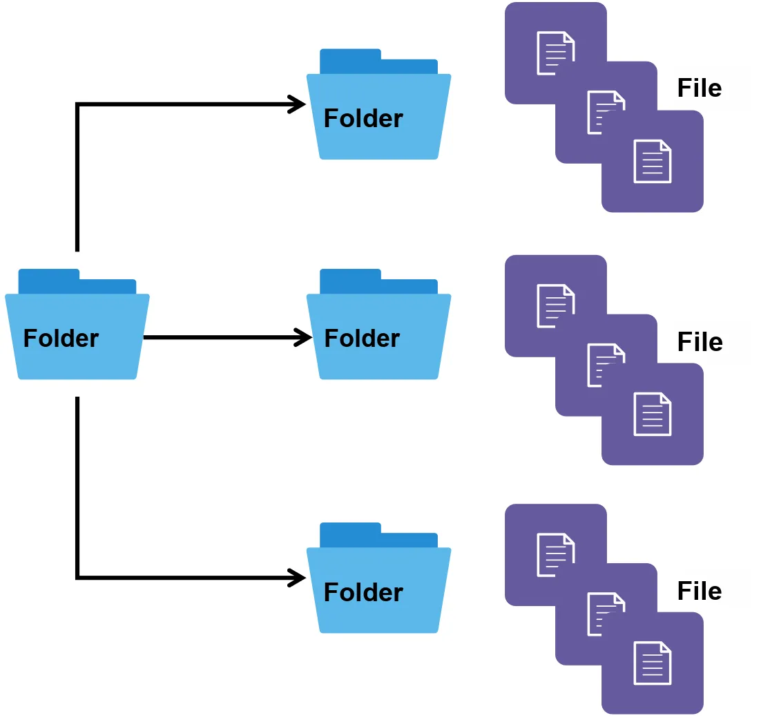
Typically, a file system has the following functions:
- File Management: including operations such as file creation, file reading, file writing, and file deletion;
- Directory Management: including operations such as directory creation, directory reading, and directory deletion;
- Storage Management: including operations such as allocating storage space for files and tracking storage usage.
FAT is one of the simple and easy-to-understand file systems (commonly used in embedded devices). First, let’s supplement a basic concept that every beginner must know:
- Cluster: The "smallest unit" for a file system to store data:
- Divide the storage device into numerous "small grids" of the same size, and each grid is a cluster;
- A file occupies one or more "cells"(clusters); even a very small file will take up at least one cluster.
Taking the FAT file system as an example, a complete file system usually consists of the following parts: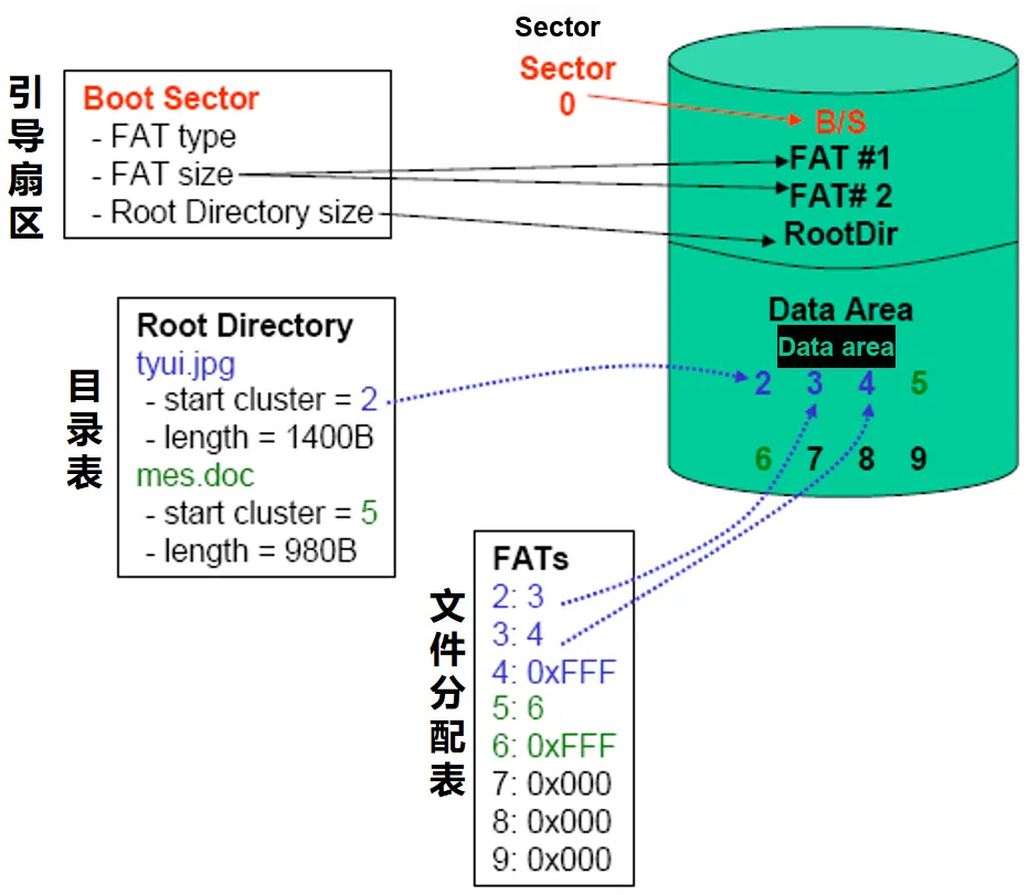
- Boot Sector: It serves as the "instruction manual" of the file system, corresponding to the "Boot Sector" area in the diagram. As the "first piece of information" on a storage device, it is analogous to the "user manual" of a drawer, and records the following contents:
- File system type (whether it is FAT12/FAT16 or FAT32);
- how much space each cluster occupies, the location of the FAT table, and the size of the root directory (corresponding to the "FAT type, FAT size, Root Directory size" in the Boot Sector in the figure).
- When the device starts up, read this "instruction manual" first to learn how to identify the subsequent files.
- Directory Table: It serves as the "inventory list" of files, corresponding to the "Root Directory" in the diagram. As the "file manifest" of a storage device, it records the key information of each file:
- File name (e. g., tyui.jpg, mes.doc
tyui.jpg,mes.docin the figure); - File size (e. g.
tyui.jpgis 1400B); - Which cluster the file is stored in ("starting cluster number", for example,
tyui.jpgstarts to be stored from cluster 2); - When you need to find a file, first check this "list", and you will know "what the file is called, how large it is, and which cluster to start searching from".
- File name (e. g., tyui.jpg, mes.doc
- File Allocation Table (FAT): a "destination map" for clusters, corresponding to the "FATs" area in the diagram. It is essentially a "cluster relationship table"(which can be understood as an array). Since a single file may occupy multiple clusters (for example, a large file), the FAT records "which cluster is the next one for each cluster":
- Each entry in the table corresponds to a cluster, and the meaning of the value is as follows:
0x0000: This cluster is empty (available);0xFFFF: This cluster is the last cluster of the file (end marker);0xFF7F: This cluster is bad (cannot store data).
tyui.jpg's starting cluster is 2:- Check the FAT: the entry corresponding to "2" is "3";
- The next cluster of cluster 2 is 3;
- "3 corresponds to 4";
- The next cluster of cluster 3 is 4;
- "4 corresponds to 0xFFFF";
- Cluster 4 is the last cluster. Therefore,
tyui.jpgexists in clusters 2,3 and 4.
mes.docstarts at cluster 5:- In FAT, "5 corresponds to 6";
- The one following cluster 5 is 6;
- "6 corresponds to 0xFFFF"
- End. Therefore,
mes.docexists in clusters 5 and 6.
- Each entry in the table corresponds to a cluster, and the meaning of the value is as follows:
- Data Area: The "actual storage area" of a file, corresponding to the "Data Area" in the diagram, is the location on a storage device that actually holds file content; the actual data of all files (such as the image content of
tyui.jpgand the document content ofmes.doc) are stored in the clusters here.- The aforementioned "manifest" and "map" are merely auxiliary tools; the actual file content is stored in these clusters.
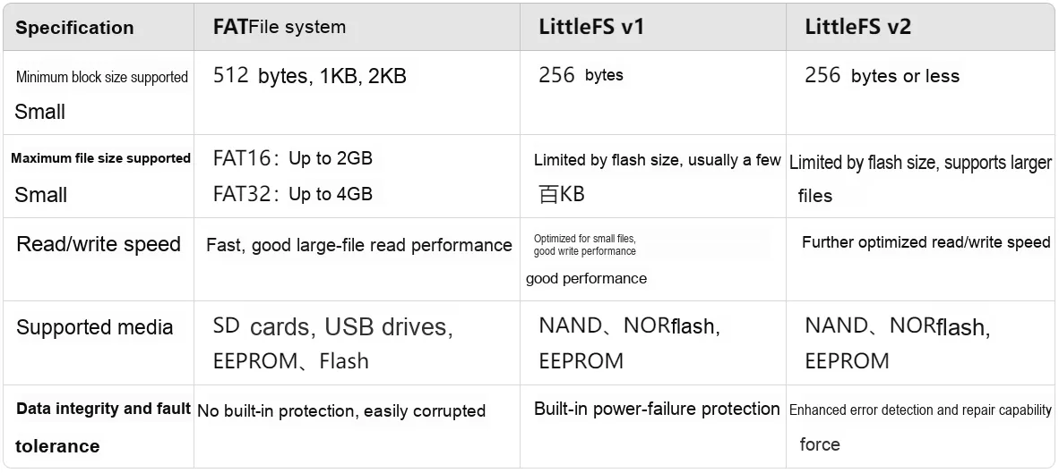
Common file system types include FAT (FAT12, FAT16 and FAT32), NTFS, ext, LittleFS, etc. Among them, the FAT file system is a commonly used file system for embedded devices, featuring simple design, easy implementation and understanding, and low overhead. However:
- The maximum file size supported by the FAT file system is relatively small (for example, FAT16 only supports files up to 2GB);;
- Meanwhile, fragmentation may occur during use (when files are stored in clusters scattered here and there, leading to slower access speed), which will affect performance;
- Furthermore, it has no built-in permissions (anyone can modify files) or security mechanisms, resulting in weak data protection (files are difficult to recover once corrupted).
In MicroPython, the three most commonly used file systems are FAT, LittleFS v1 and LittleFS v2, and their comparison is as follows:
1.4.2 VFS Virtual File System
First, let’s cover 2 basic concepts that every beginner must know to help you quickly understand VFS:
- Abstraction layer: It can be understood as a "universal interpreter": no matter what "dialect"(different file systems) the underlying layer uses, it converts them into a set of "common language"(unified operation methods) for you to use.
- Block device: A general term for storage devices (such as SD cards and the built-in flash memory of development boards). This type of device reads and writes data in "blocks" of a fixed size, and serves as the carrier of the file system.
In MicroPython, VFS (Virtual File System) is a module designed to provide file system support for embedded devices. As an abstraction layer, it offers a unified file system interface:
- enabling applications to access different types of underlying file systems (such as FAT, SPIFFS, LittleFS, etc.) via the same API, without the need for applications to concern themselves with the specific implementation of the underlying file system;
- Simply put, whether you are using the FAT system for SD cards or the LittleFS system built into the development board, VFS provides you with an identical set of operation methods (such as saving and reading files), so you don’t need to learn new commands just because you have switched to a different storage device.
Additionally, users can mount different types of file systems to specific paths and unmount them when necessary: you can think of "mounting" as "adding an access point" for a storage device — for example, "connecting" an SD card to the /sd folder in the system, after which you can operate the SD card simply by accessing /sd; "unmounting", on the other hand, means safely "removing" this access point to prevent data corruption.
For example, we can mount the FAT file system of an SD card to /sd, and at the same time mount a SPIFFS file system to /spiffs, and manage files through a unified file operation interface; through the VFS module, we can also create a block device (a device that performs read and write operations in units of blocks) at the software level to simulate the behavior of a storage device. For instance, we can create a virtual RAM block device in an embedded system or operating system.
VFS provides the following methods for mounting and unmounting file systems:
vfs.mount (fsobj, mount_point, *, readonly): Mount a storage device to a mount point- Description: To "mount" a file system object (e. g. FAT/LittleFS) to a specific path in the system (e. g.
/sd), after which the storage device can be accessed and operated via this path. - Plain-English Explanation of Parameters:
fsobj: The file system object to be mounted (such as the FAT/LittleFS object to be introduced later), or directly fill in a block device (such as the object of an SD card).mount_point: "entry path" — for example,'/'denotes the system root directory, and'/sd'denotes the dedicated entry for the SD card.readonly(optional): If set toTrue, this storage device is read-only and cannot be modified; if set toFalse(default), it supports both read and write operations.
- Exception Prompt: If this "entry path" is already occupied by another device (e. g.,
/sdhas already mounted another SD card), an error will be reportedOSError (EPERM).
- Description: To "mount" a file system object (e. g. FAT/LittleFS) to a specific path in the system (e. g.
vfs.umount (mount_point): Safely "eject"- Description: Unmount the previously mounted file system. For example, unmount the SD card after use to avoid data loss caused by directly pulling out the card.
- Parameter: Fill in the "mount entry path" to be unmounted (e. g.,
'/sd'), or directly fill in the previously mounted file system object. - Exception Prompt: If the "entry path" you filled in has never had a device mounted, an error will be reported
OSError (EINVAL).
VFS only acts as a "manager", you need to first create a file system object of the corresponding type (such as FAT / LittleFS) before you can mount and use it. Below are the common file system classes (corresponding to the class descriptions you provided).
The following are file system implementation classes, which can be used to build file systems such as FAT, LittleFS v1, and LittleFS v2:
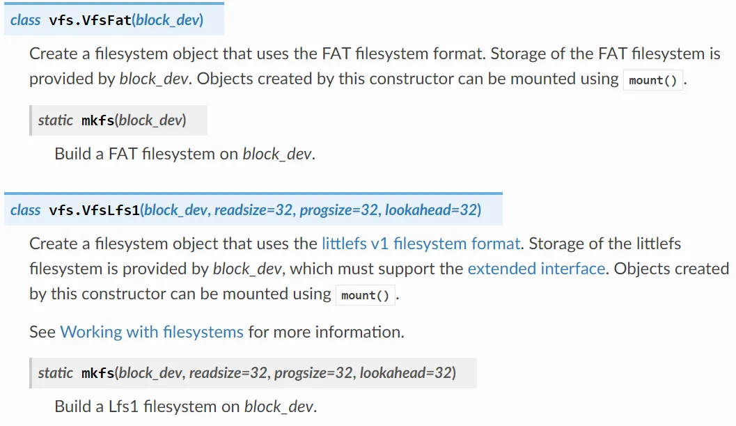
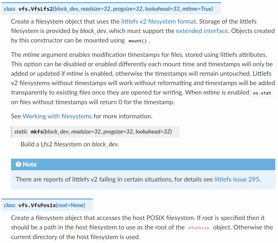
As shown below:
vfs.VfsFat (block_dev): Create a FAT file system object- Function: Creates an object that manages storage in FAT format (e. g., the FAT format commonly used for SD cards),
block_devrefers to the block device to be managed (e. g., an SD card object). mkfsmethod: This is a "formatting" function — for example,vfs.VfsFat.mkfs (sd_dev)formats the SD card (sd_dev) into the FAT file system, so that files can be stored on it afterwards.
- Function: Creates an object that manages storage in FAT format (e. g., the FAT format commonly used for SD cards),
vfs.VfsLfs1 (block_dev, . ..)/vfs.VfsLfs2 (. ..): Create a LittleFS filesystem object- LittleFS is a lightweight file system commonly used in embedded devices (more suitable for small flash memory than FAT), and it has two versions: v1 and v2.
- Function: Creates an object that manages storage in LittleFS format, where
block_devis the corresponding block device (e. g., the built-in flash memory of the development board). - Parameters (optional):
readsize/progsizeetc. refer to the block sizes for read/write / write operations (beginners can just use the default value32); themtimeparameter of the v2 version is used to record the file modification time. mkfsmethod: for examplevfs.VfsLfs2.mkfs (flash_dev)is to format the development board's flash memory (flash_dev) into the LittleFS v2 system.
- Function: Creates an object that manages storage in LittleFS format, where
vfs.VfsPosix (root= None): Access the computer's file system (for debugging only)- Function: When running MicroPython on a computer, it is used to access the computer's own file system (such as the C drive and D drive of the computer).
rootFill in the path on the computer (for example'C:/test'). If left blank, the current folder will be used by default.
- Function: When running MicroPython on a computer, it is used to access the computer's own file system (such as the C drive and D drive of the computer).
The following table shows the file systems included in the MicroPython firmware for different chips by default:
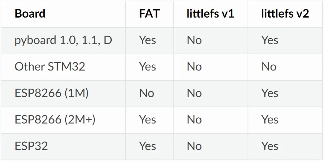
1.4.3 Block Devices
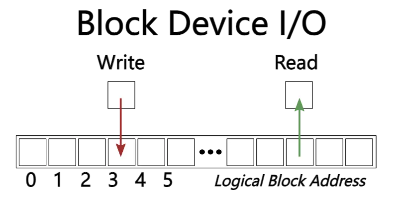
A file system is built on top of block devices, which are a type of storage device that divides the storage space into fixed-size blocks and allows random access to these blocks — meaning each block has a unique address and can be read from or written to independently. Put simply, block devices store data in blocks, and the file system organizes these blocks into files and directories, enabling users to access and manage data conveniently.
- It divides the storage space into numerous uniformly sized "blocks"(for example, each block is 1KB), and each block has a unique "Logical Block Address"(such as 0,1, 2,3.. . in the diagram);
- When reading or writing data, you can directly operate the corresponding block by specifying its "block address" — for example, in the diagram, you write data to the block at address 3 and read the block at address 8, without having to iterate sequentially starting from 0; just locate the number of whichever block you want to operate on.
- A file system (such as FAT or LittleFS) organizes these "blocks" into files and directories — for example, a file may occupy Block 3, Block 4, and Block 5, and the file system keeps track of "which blocks correspond to this file".
Character Devices and Stream Devices
Character devices perform data transmission in units of characters, do not support random access, and usually conduct data reading and writing in a sequential manner; for example, serial communication peripherals, keyboards, and mice are all character devices, which are often used for streaming data transmission, real-time data input and output and other such requirements.
A "Stream Device" is an extended or supplementary concept of character devices, mainly used to process continuous, streaming data streams. The data transmission methods of these devices are usually similar to those of character devices, but they focus on meeting the needs of dynamic data stream processing. Common stream devices include network streams (such as network interface cards), audio streams (such as microphones and speakers), video streams (such as cameras), Streaming Media devices (such as webcams, Real Time Communication transmission devices), etc.
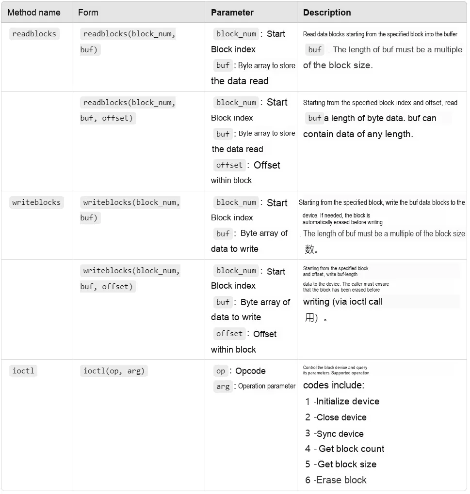
MicroPython does not provide operation methods for block devices, but it offers an abstract block device interface vfs.AbstractBlockDev class. This template specifies the methods that a block device must implement (such as "read data from a certain block" and "write data to a certain block"), which is equivalent to the "format of an answer sheet for an exam". Only by writing code in accordance with this template can MicroPython recognize it as a block device and then create a file system on it.
The actual block device class must implement the methods described below:
2. Software Control Method
2.1 os Module
The os module provides the following methods for operations such as file reading and writing, directory creation, etc. :
Method Name | input parameters | Return Parameters | Function Description |
os.uname() | None |
| Returns a tuple containing the system name, node name, system version, MicroPython version, and hardware identifier. |
os.urandom (n) |
|
| Returns a bytes object containing |
os.chdir(path) |
| None | Change the current working directory to the specified |
os.getcwd() | None | Current working directory path (string) | Returns the path of the current working directory. |
os.ilistdir ([dir]) |
| An iterator that returns | Lists the contents of the specified directory (or the current directory) and returns an iterator of tuples containing the name, type, inode, and (optionally) size. |
os.listdir ([dir]) |
| Table of Contents Content List (List Type, String) | Lists the contents of the specified directory (or the current directory) and returns a list of the names of files and directories. |
os.mkdir(path) |
| None | Create a new directory with the path |
os.remove(path) |
| None | Delete the file at the specified path. |
os.rmdir (path) |
| None | Delete the empty directory at the specified path. |
os.rename (old_path, new_path) |
| None | Rename the file or directory from |
os.stat(path) |
| File or directory status information (tuple) | Obtain the status information of a file or directory, such as file size, permissions, modification time, etc. |
os.statvfs(path) |
| File System Status Information (Tuple) | Returns status information of the file system, such as block size, available blocks, number of files, etc. |
os.sync() | None | None | Synchronizes all changes on the file system to the disk. Typically, file operations such as |
os.dupterm (stream_object, index=0) |
| the previous stream object or | Retarget the terminal's input and output to the specified |
2.2 vfs Virtual File Module
vfs (virtual file system) module contains the functions for creating file system objects as well as mounting and unmounting these file systems.
The functions of the file system mounting are as follows:
Method Name | input parameters | Return Parameters | Function Description |
vfs.mount(fsobj, mount_point, *, readonly) | - | None | Mount the file system object |
vfs.umount(mount_point) | - | None | Unmount the file system mounted at the specified location, which supports specification via a Mount Point or file system object; during the unmount process, the |
The following are the mountable file system types:
Class Name | Input parameters | Return Parameters | Function Description |
vfs.VfsFat(block_dev) | - | file system object | Create a file system object formatted with the FAT file system, where |
vfs.VfsLfs1 (block_dev, readsize=32, progsize=32, lookahead=32) | - | file system object | Create a file system object using the littlefs v1 file system format, |
vfs.VfsLfs2(block_dev, readsize=32, progsize=32, lookahead=32, mtime=True) | - | file system object | Create a file system object using the littlefs v2 file system format, with |
vfs.VfsPosix(root=None) | - | file system object | Creates a filesystem object to access the host's POSIX filesystem. If |
2.3 Block Device Abstract Class
vfs.AbstractBlockDev is an abstract class for implementing block devices, and concrete block device classes must implement the methods described below:
Method Name | input parameters | Return Parameters | Function Description |
readblocks(block_num, buf) | - | None | Starting from the specified |
readblocks (block_num, buf, offset) | - | None | Read any number of bytes starting from the specified |
writeblocks(block_num, buf) | - | None | Writes the data in the |
writeblocks (block_num, buf, offset) | - | None | Write the data in |
ioctl (op, arg) | - | Depending on the opcode, this may be an integer, | Controls a block device and executes the functions specified by different operation codes. Common operations include: initializing the device ( |
3. Application Examples
3.1 File Read and Write Operations
In the following code, we use the os module in MicroPython to implement a file read and write routine. This code reads data from the ADC internal temperature sensor, writes the data to a file, and simultaneously reads the data from that file.
The following code can be found in the elegance-devkit v1\Demo\70 FileSys_WriteRead folder in the resource package we provide.
The sample code is shown below:
# Python env   : MicroPython v1.23.0
# -*- coding: utf-8 -*-
# @Time    : 2024/9/16 11:58 AM
# @Author  : Li Qingshui
# @File    : main.py
# @Description : File system experiment, using the os module to read and write files and redirect the terminal

# ======================================== Import Modules =========================================

# Import the operating system module, which provides file operations
import os
# Import the hardware module
from machine import ADC
# Import time-related modules
import time

# ======================================== Global Variables ============================================

# Define the file path used to store the temperature sensor data
file_path = "temperature_data.txt"

# ======================================== Functions ============================================

def read_temperature() -> float:
    """
    Reads the ADC value and converts it to a temperature in degrees Celsius; applies to the Raspberry Pi Pico internal temperature sensor.

    Implementation steps:
    1. Read the raw 16-bit ADC value
    2. Convert it to a 0-3.3V voltage value
    3. Apply the conversion formula for the RP2040 chip's built-in temperature sensor
    4. Round the value

    Args:
        None

    Returns:
        float: The converted temperature value in degrees Celsius, with two decimal places

    Raises:
        OSError: Raised when the ADC read fails
        ValueError: Raised when an invalid temperature value is calculated
    """

    # Declare global variables
    global sensor_temp

    # Read the ADC value; the ADC range is 0~65535, and the supply voltage is assumed to be 3.3V
    adc_value = sensor_temp.read_u16()
    # Convert the ADC value to a voltage; the ADC has 16-bit resolution
    voltage = adc_value * 3.3 / 65535
    # Use the Raspberry Pi Pico temperature formula to convert the voltage to a temperature (this is the conversion formula for the Pico's internal temperature sensor)
    temperature = 27 - (voltage - 0.706) / 0.001721

    # Keep two decimal places
    temperature = round(temperature, 2)
    # Return the temperature value
    return temperature

# ======================================== Custom Classes ============================================

# ======================================== Initialization ==========================================

# Power-on delay
time.sleep(3)
# Print debug information
print("FreakStudio : Save temperature data to file system")

# Initialize the internal temperature sensor
sensor_temp = ADC(4)

# ========================================  Main Program  ===========================================

# Open the file in write mode; create it if it does not exist
file = open(file_path, "w")
# Get the initial time when the program started running
start_time = time.ticks_ms()

# Print debug information
print("Start to record temperature data")
# Start recording temperature data and write it to the file
for i in range(10):
    # Read the current temperature
    temp = read_temperature()
    # Record the current run time
    current_time = time.ticks_ms()
    # Calculate the run time interval
    time_diff = time.ticks_diff(current_time, start_time)
    # Print debug information indicating that writing is in progress
    print("File Writing...")
    # Write the recorded time difference (in milliseconds) and the temperature to the file
    file.write("Time: {} ms, Temperature: {:.2f} °C\n".format(time_diff, temp))
    # Sync the file system after each write to make sure the data is saved
    os.sync()
    # Sleep for 10ms
    time.sleep_ms(10)

# Close the file
file.close()
# Print debug information
print("File Writing Finished")

# To verify the file contents, reopen the file, read it and display it
# Reopen the file in read-only mode
file = open(file_path, "r")
# Print debug information
print("File Read Start :")

# Read the file contents line by line
for line in file:
    # Print the file contents to the console
    print(line.strip())

# Close the file
file.close()
Here, we first use ADC channel 4 to access the internal temperature sensor, and define a read_temperature function that can convert ADC values to voltage, and then convert the voltage to Celsius temperature using the temperature conversion formula provided by Raspberry Pi Pico; after that, we create a file named temperature_data.txt and operate it in write mode.
In the main program section, perform the following operations:
- Open the file
temperature_data.txtin write mode; record the initial time when the program starts running viatime.ticks_ms (), which is used to calculate the time difference subsequently. - Loop 10 times, read the current temperature data and record the time difference each time, write the time difference and temperature data into a file in text format, and use
os.sync ()to synchronize the file system to ensure data security. - After completing data writing, close the file
file.close ()to ensure proper release of resources. - Reopen the file in read-only mode
temperature_data.txt, read the file content line by line, and useprint ()to display the content on the Console for verification. Finally, close the file to complete the program execution.
Here, it should be noted that os.sync () function is used in MicroPython to synchronize the cached data of the file system, that is, to force the data in the buffer that has not yet been written to the disk to be written to the file system; normally, file operations (such as write () or close ()) will write data to the cache, and only under specific conditions (such as when a file is closed or the cache is full) will the data be written to the actual storage medium.
In embedded systems, especially devices using file systems such as flash memory and SD cards, unsynchronized file data may be lost or corrupted if the system is suddenly powered off. If a program is performing a long-term file write operation, for data security considerations, it can periodically call os.sync () to ensure that the data written previously will not be lost even if the program is interrupted midway.
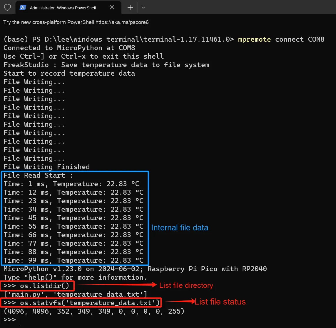
Burn the code, open the terminal, and the following content will be displayed:
3.1 Application Experiment.mp4 3.2 MB
As you can see, after we write the time difference and temperature data to the file temperature_data.txt, we can successfully read the content in the file and print it to the terminal.
After the code finishes executing, we use the function os.listdir () to list the current directory, and we can see that the file temperature_data.txt already exists in the file system; we can also use the os.statvfs () function to read the file status, which returns a tuple containing file system information:
f_bsize– The block size of the file system is 4096 bytes.f_frsize– The fragment size is also 4096 bytes.f_blocks– The total number of blocks in the file system is 352.f_bfree– The number of free blocks remaining in the current file system is 349.f_bavail– the number of free blocks available to non-privileged users is also 349.f_files– The total number of inodes in the file system is 0, indicating that this file system may not use inodes.f_ffree– The number of free inodes remaining in the file system is 0.f_favail– the number of free inodes available to non-privileged users is also 0.f_flag– the mount flag of the file system, which usually indicates specific attributes of the file system such as read-only; the value 0 here means no special flags are set.f_namemax– This file system allows a maximum filename length of 255 characters.
Here, multiplying f_bsize and f_blocks yields the size of the internal file system of the Raspberry Pi Pico as 1441792 bytes, which is 1.37 MB.
3.2 Custom Logging Function
In the following code, we use a custom class to implement a logging module that supports the following features: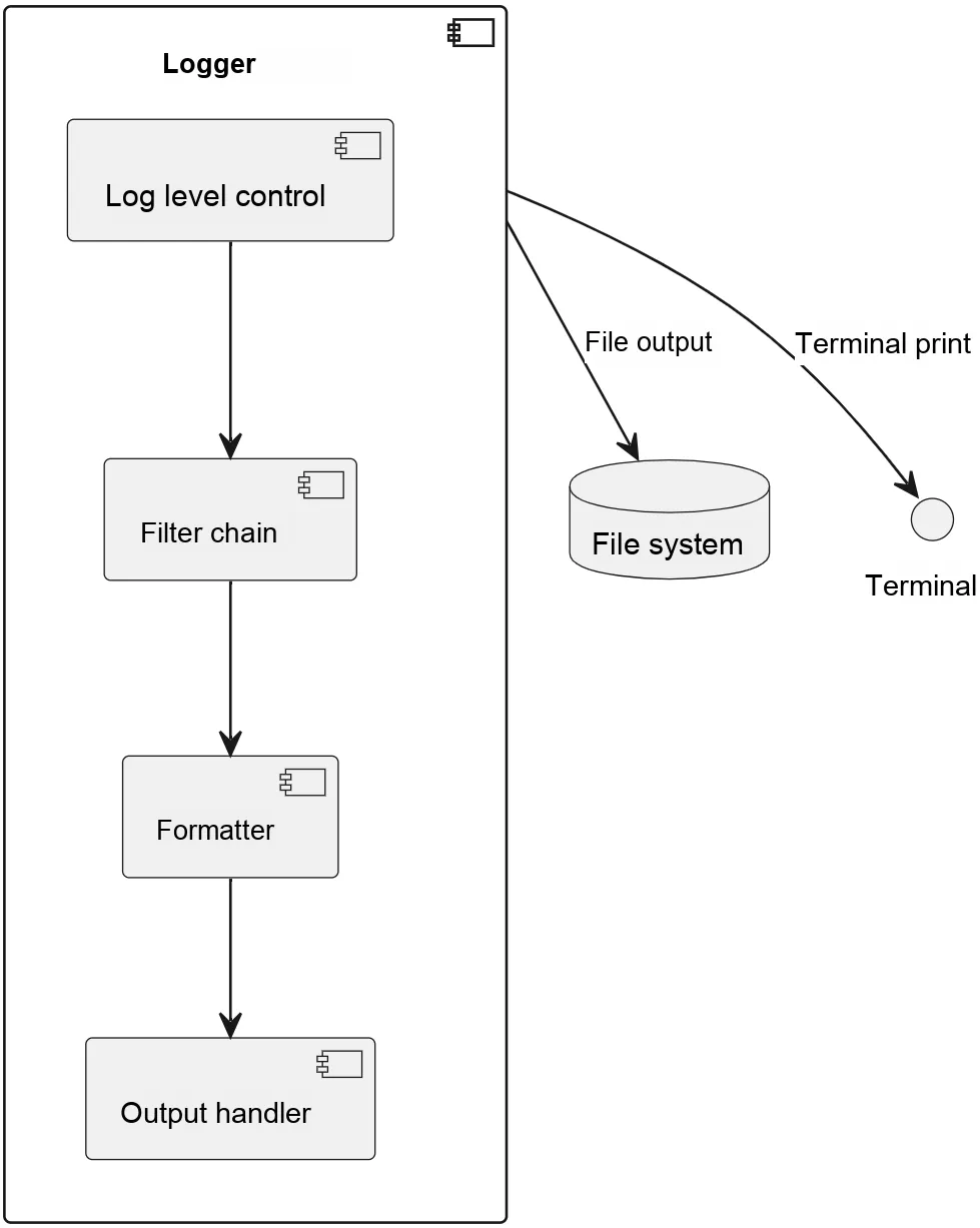
- Define log levels: Define different log levels, such as
DEBUG,INFO,WARNING,ERRORandCRITICAL. - Implement a log filter: Filter log messages based on log levels.
- Implement a log formatter: to format the output of log messages.
- Create a logger: Combine the logger, filter, and formatter together.
- Log File Rotation: When the log file reaches the specified maximum number of entries or the rotation time interval, a new log file will be created automatically, and the log entry counter will be reset.
- Exception handling: Supports recording exception stack information, and allows users to choose whether to display exception information in the terminal.
- Thread Safety: Mutex locks are used to ensure thread safety in a multi-threaded environment and prevent race conditions during log writing.
The sample code is as follows:
# Python env   : MicroPython v1.23.0
# -*- coding: utf-8 -*-
# @Time    : 2024/9/16 2:40 PM
# @Author  : Li Qingshui
# @File    : logger.py
# @Description : Logging module with level classification, log filter and formatter features

# ======================================== Import Modules =========================================

# Import the time module, used to get the current time
import time
# Import the os module, used for file operations
import os
# Import the threading module and locks
import _thread
# Import system-related modules
import sys
# Import the micropython module, used to optimize code
import micropython

# ======================================== Global Variables ============================================

# ======================================== Functions ============================================

# ======================================== Custom Classes ============================================

# Define the log levels
class LogLevel:
    DEBUG    = 1 # Debug level
    INFO     = 2 # Info level
    WARNING  = 3 # Warning level
    ERROR    = 4 # Error level
    CRITICAL = 5 # Critical error level

# Logger class
class uLogLite:
    """
    Logger class that provides multi-level logging, filtering and formatting, and supports file rotation and thread-safe operation.

    This class encapsulates the complete logging process, including log level filtering, message formatting, file output and rotation management.
    It supports flexible log filtering through a filter chain, and the log output style can be customized through a formatter.

    Attributes:
        name (str): Logger identifier name, used to generate the log file name prefix
        level (int): Current log level (LogLevel enum value)
        filters (List[Callable[[int, str], bool]]): List of log filter functions
        formatter (Optional[object]): Log formatter instance; must implement the format(level, message) method
        output (str): Output target. "terminal" means terminal output; any other string is a folder path. Only single-level folder paths are supported here.
        max_logs (int): Maximum number of log entries per log file
        rotate_interval (int): Log rotation time interval (unit: hours)
        log_count (int): Number of log entries recorded in the current file
        last_rotation_time (float): Timestamp of the last rotation (UNIX timestamp)
        lock (Lock): Thread mutex lock object
        log_file (Optional[TextIO]): Current log file handle

    Methods:
        __init__(self, name: str, level: int = LogLevel.DEBUG, output: str = "terminal",
                max_logs: int = 1000, rotate_interval: int = 24) -> None:
            Initialize the logger instance

        add_filter(self, log_filter: Callable[[int, str], bool]) -> None:
            Add a log filter function

        set_formatter(self, formatter: object) -> None:
            Set the log formatter instance

        log(self, level: int, message: str) -> None:
            Base log recording method

        debug(self, message: str) -> None:
            Record a DEBUG-level log

        info(self, message: str) -> None:
            Record an INFO-level log

        warning(self, message: str) -> None:
            Record a WARNING-level log

        error(self, message: str) -> None:
            Record an ERROR-level log

        critical(self, message: str) -> None:
            Record a CRITICAL-level log

        exception(self, exc: Exception, terminal_display: bool = True) -> None:
            Record exception stack trace information

        close(self) -> None:
            Safely close the log file

    Private Methods:
        _open_log_file(self) -> None:
            Open/create the log file and initialize the counter

        __is_single_level_path(self, path: str) -> bool:
            Check whether the path is a valid single-level folder path (for the MicroPython file system)

        _apply_filters(self, level: int, message: str) -> bool:
            Apply all registered filters

        _format_message(self, level: int, message: str) -> str:
            Format the log message

        _write_log(self, formatted_message: str) -> None:
            Thread-safe log write operation

        _should_rotate(self) -> bool:
            Check whether the rotation condition is met

        _rotate_log_file(self) -> None:
            Perform log file rotation
    """
    def __init__(self, name: str, level: int = LogLevel.DEBUG, output: str = "terminal",
                 max_logs: int = 1000, rotate_interval: int = 24) -> None:
        """
        Logger initialization

        Args:
            name (str): Logger identifier name
            level (int): Default log level (LogLevel enum)
            output (str): Output target, "terminal" or a folder path. Only single-level folder paths are supported here.
            max_logs (int): Maximum number of log entries
            rotate_interval (int): Log rotation time interval (hours)

        Raises:
            OSError: Raised when file creation fails, name is empty or an empty string, level is not in the LogLevel enum, or output is not a string.
        """
        # Check whether name is empty or an empty string
        if not name or name == "":
            raise ValueError("name cannot be empty")

        # Check whether name is a string
        if not isinstance(name, str):
            raise TypeError("name must be a string")

        # Check whether level is an integer and a value in LogLevel
        if not isinstance(level, int) or level not in [getattr(LogLevel, attr) for attr in dir(LogLevel) if
                                                       not attr.startswith('__')]:
            raise TypeError("level must be an integer of LogLevel enum")

        # Check whether output is valid
        if not isinstance(output, str):
            raise TypeError("output must be a string")

        # Verify that output is only a single-level folder path
        if output != "terminal":
            if not self._is_single_level_path(output):
                raise ValueError(
                    "Output path must be a single-level directory\n"
                    "Examples: 'logs', '/data', 'mylog'"
                )

        # Initialize the logger; accepts the log name, log level, and output method (file or terminal)
        self.name = name
        self.level = level
        # Initialize the filter list
        self.filters = []
        # Initialize the formatter
        self.formatter = None
        # Log output method: can be "terminal" or a folder path
        self.output = output
        # Maximum number of log entries
        self.max_logs = max_logs
        # Rotation time interval (hours)
        self.rotate_interval = rotate_interval

        # Initialize the log entry counter
        self.log_count = 0
        # Record the last rotation time
        self.last_rotation_time = time.time()

        # Create the mutex lock
        self.lock = _thread.allocate_lock()

        # Open the log file
        self._open_log_file()

    @staticmethod
    def _is_single_level_path(path: str) -> bool:
        """
        Check whether the path is a valid single-level folder path (for the MicroPython file system)

        Single-level folder paths support the following formats:
            "logs"    - Relative path under the current directory
            "/logs"   - Absolute path under the root directory
            "" or "." - Current directory
            "/"       - The root directory itself

        Args:
            path (str): Path string to check

        Returns:
            bool: Returns the check result:
                - True:  Valid single-level path
                - False: Multi-level path or contains illegal characters
        """
        # Empty path or current directory
        if not path or path == "." or path == "/":
            return True

        # Normalize the path (handle leading/trailing slashes)
        normalized = path.strip("/")

        # Check whether it contains a subpath separator
        return "/" not in normalized and "\\" not in normalized

    @micropython.native
    def _open_log_file(self) -> None:
        """
        Create/open the log file. If the file already exists, read its line count to initialize the counter; for a new file the counter starts from 0.

        Args:
            None

        Returns:
            None

        Raises:
            OSError: Raised when file creation fails

        Notes:
            - File name format: {name}_{year-month-day_hour-minute-second}.txt
            - Automatically falls back to terminal output on failure
        """
        # Get the current time: format is (year, month, mday, hour, minute, second, weekday, yearday)
        t = time.localtime()
        # Record the timestamp and format it as a year-month-day_hour-minute-second string (e.g., 20240917_143001)
        timestamp = "{:04}{:02}{:02}_{:02}{:02}{:02}".format(t[0], t[1], t[2], t[3], t[4], t[5])

        # If output is to the terminal
        if self.output == "terminal":
            # Set the log file handle to None; terminal mode needs no file operations
            self.log_file = None
            self.log_count = 0
        else:
            # Generate the log file name from the name and timestamp: name_timestamp.txt
            log_filename = f"{self.output}/{self.name}_{timestamp}.txt"

            # Try to create the directory (only single-level directories are handled)
            try:
                os.mkdir(self.output)
            except OSError:
                # Ignore if the directory already exists
                pass

            try:
                # Check whether the file already exists
                try:
                    os.stat(log_filename)
                    file_exists = True
                except OSError:
                    file_exists = False

                # Open the file in append mode (created if it does not exist)
                self.log_file = open(log_filename, 'a')

                # Line count
                if file_exists:
                    count = 0
                    with open(log_filename, 'r') as f:
                        while True:
                            # Read in 128-byte chunks (suited to memory-constrained environments)
                            chunk = f.read(128)
                            # Reached the end of the file
                            if not chunk:
                                break
                            # Count the newline characters (one per line)
                            count += chunk.count('\n')
                    self.log_count = count
                else:
                    # If it is a newly created file, initialize the counter
                    self.log_count = 0
            except OSError as e:
                # Failed to open the file; print the error message
                print(f"无法打开文件 {log_filename}: {e}")
                # Set the file handle to None
                self.log_file = None

    def add_filter(self, log_filter: callable[[int, str], bool]) -> None:
        """
        Add a log filter

        Args:
            log_filter (callable): Filter function; receives (level, message) and returns bool

        Returns:
            None
        """
        # Add the log filter
        self.filters.append(log_filter)

    def set_formatter(self, formatter: object) -> None:
        """
        Set the log formatter

        Args:
            formatter (object): Object that implements the format(level, message) method
            Must have a format(level, message) method for formatting log messages

        Returns:
            None

        Raises:
            TypeError: Raised when the formatter does not implement the format(level, message) method
        """
        # Check whether the formatter implements the format(level, message) method
        # hasattr(formatter, "format") checks whether formatter has a format attribute
        # callable(getattr(formatter, "format")) ensures format is a callable method rather than a plain attribute
        if not hasattr(formatter, "format") or not callable(getattr(formatter, "format")):
            raise TypeError("formatter must implement a callable format(level, message) method")

        # Set the log formatter
        self.formatter = formatter

    def _apply_filters(self, level: int, message: str) -> bool:
        """
        Apply all registered filters. If any filter returns False, the log is not recorded.

        Args:
            level   [int]: Log level
            message [str]: Log message

        Returns:
            bool: Passes when all filters return True
        """
        # Apply the log filters; if any filter returns False, the log is not recorded
        for log_filter in self.filters:
            if not log_filter(level, message):
                return False
        return True

    @micropython.native
    def _format_message(self, level: int, message: str) -> str:
        """
        Format the log message. If a formatter is set, use it; otherwise use the default format.

        Args:
            level   [int]: Log level.
            message [str]: Log message.

        Returns:
            str: The complete formatted log entry.
        """
        # If a formatter is set, use it; otherwise use the default format
        if self.formatter:
            return self.formatter.format(level, message)
        return f"{self.name} - {level}: {message}"

    @micropython.native
    def _write_log(self, formatted_message: str) -> None:
        """
        Thread-safe log write operation. Choose the write method according to the log output method; it can write to a file or the terminal.

        Execution flow:
            1. Acquire the thread lock
            2. Check the rotation condition
            3. Perform the actual write
            4. Update the counter
            5. Release the lock

        Args:
            formatted_message [str]: The complete formatted log entry.

        Returns:
            None

        Notes:
            - Automatically handles log rotation
            - Falls back to terminal output on write failure
        """

        # Lock the thread to ensure thread safety
        with self.lock:
            # # Record the log write start time
            # start_time = time.ticks_us()

            # Check whether rotation is needed before writing the log
            if self.output != "terminal" and (self.log_count >= self.max_logs or self._should_rotate()):
                # Perform rotation
                self._rotate_log_file()

            # Write log; if file output is set, write to the file, otherwise output to the terminal
            if self.output == "terminal":
                # Output to terminal
                print(formatted_message)
            else:
                # If the file handle is valid, write to the log file
                if self.log_file:
                    # Write the message and append a newline
                    self.log_file.write(formatted_message + "\n")
                    # Flush the log message to the buffer immediately
                    self.log_file.flush()
                    # Increment the log count counter
                    self.log_count += 1

                else:
                    # If the file handle is invalid, output to the terminal
                    print("can not open file, output to terminal:", formatted_message)

            # # Record the log write end time
            # end_time = time.ticks_us()
            # # Calculate the log write duration
            # # Calculate the elapsed time
            # write_time = time.ticks_diff(end_time, start_time)
            # # Print the elapsed time in ms
            # print(f"write log cost {write_time / 1000} ms")

    def _rotate_log_file(self) -> None:
        """
        Perform log file rotation, including closing the current file, creating a new file, and resetting the counter.

        Args:
            None

        Returns:
            None

        Raises:
            OSError: Raised when a file operation fails
        """
        # # Debug output
        # print(f"[Rotation] Count:{self.log_count} Max:{self.max_logs}")

        # If the file handle is valid
        if self.log_file:
            # Close the current log file
            self.log_file.close()
        # Open a new log file
        self._open_log_file()
        # Reset the log count counter
        self.log_count = 0
        # Update the last rotation time
        self.last_rotation_time = time.time()

    @micropython.native
    def _should_rotate(self) -> bool:
        """
        Check whether the log rotation condition is met.

        Args:
            None

        Returns:
            bool: Returns True if rotation is needed, otherwise False
        """
        # Calculate the difference between the last rotation time and the current time
        current_hour = time.localtime()[3]
        last_hour = time.localtime(self.last_rotation_time)[3]
        time_diff = time.time() - self.last_rotation_time

        # The time condition is met if any of the following holds:
        # 1. The interval in hours has been reached
        # 2. The hour has changed and the time difference exceeds 1 hour (handles crossing days)
        return (time_diff >= self.rotate_interval * 3600) or \
            (current_hour != last_hour and time_diff >= 3600)

    @micropython.native
    def log(self, level: int, message: str) -> None:
        """
        Base logging method.

        Args:
            level (int): Log level (use LogLevel enum values)
            message (str): Log content to record

        Returns:
            None

        Raises:
            ValueError: Raised when the log level is invalid or message is empty.
        """
        # Check whether level is an integer and a value in LogLevel
        if not isinstance(level, int) or level not in [getattr(LogLevel, attr) for attr in dir(LogLevel) if
                                                       not attr.startswith('__')]:
            raise TypeError("level must be an integer of LogLevel enum")

        # Check whether message is a string or an empty string
        if not isinstance(message, str) or message == "":
            raise ValueError("message must be a string")

        # Record the log; first check the log level and filters
        if level >= self.level and self._apply_filters(level, message):
            formatted_message = self._format_message(level, message)
            # Output the log according to the settings
            self._write_log(formatted_message)

    def debug(self, message: str) -> None:
        """
        Record a DEBUG level log.

        Args:
            message (str): Debug information content

        Returns:
            None
        """
        # Record a debug log
        self.log(LogLevel.DEBUG, message)

    def info(self, message: str) -> None:
        """
        Record an INFO level log.

        Args:
            message (str): General information content

        Returns:
            None
        """
        # Record an info log
        self.log(LogLevel.INFO, message)

    def warning(self, message: str) -> None:
        """
        Record a WARNING level log.

        Args:
            message (str): Warning information content

        Returns:
            None
        """
        # Record a warning log
        self.log(LogLevel.WARNING, message)

    def error(self, message: str) -> None:
        """
        Record an ERROR level log.

        Args:
            message (str): Error information content

        Returns:
            None
        """
        # Record an error log
        self.log(LogLevel.ERROR, message)

    def critical(self, message: str) -> None:
        """
        Record a CRITICAL level log.

        Args:
            message (str): Critical error information content

        Returns:
            None
        """
        # Record a critical error log
        self.log(LogLevel.CRITICAL, message)

    def exception(self, exc: Exception, terminal_display: bool = True) -> None:
        """
        Record exception stack trace information.

        Args:
            exc (Exception): Exception object
            terminal_display (bool): Whether to display in the terminal, default is True

        Returns:
            None
        """
        # Print the exception stack trace to the terminal
        if isinstance(exc, Exception):
            # Also write the exception information to the log file
            if self.output != "terminal" and self.log_file:
                sys.print_exception(exc, self.log_file)

            # If the terminal display flag is True, print the exception information to the terminal
            if terminal_display:
                sys.print_exception(exc)

    def close(self) -> None:
        """
        Safely close the log file.

        Args:
            None

        Returns:
            None
        """
        # Close the log file if file output is used
        if self.output != "terminal" and self.log_file:
            self.log_file.close()

# ======================================== Initialization ==========================================

# ========================================  Main Program  ===========================================
3.2.1 Implementation Principle of the Logger Logging Class
In the aforementioned logger logging class, we provide the following methods:
Method Name | Description |
| Initialize the logger, including the log name, level, output destination, maximum number of log entries and rotation interval. |
| Add a log filter, which is a function that determines whether a given log entry will be recorded. |
| Set up the logger formatter, which is used to define the output format of logs. |
| To record a log entry, you need to specify the log level and the log content. |
| Logs information at the DEBUG level. |
| Log information at the INFO level. |
| Log information at the WARNING level. |
| Log information at the ERROR level. |
| Log information at the CRITICAL level. |
| Record exception information, and optionally choose whether to output the exception stack in the terminal. |
| Close the log file to ensure a safe exit. |
| A private method that opens or creates a log file and initializes the counter. |
| Private method, used to check whether a path is a single-level folder path. |
| Private method that checks whether a log meets the criteria of all filters. |
| A private method that formats log information into a human-readable string. |
| A private method that writes logs to a file or outputs them to the terminal in a thread-safe manner. |
| A private method that checks whether the log rotation conditions are met. |
| A private method that performs log file rotation, creates a new log file and closes the old one. |
We have implemented methods for logging logs at different levels, such as debug, info, warning and so on, which mainly call the log method:
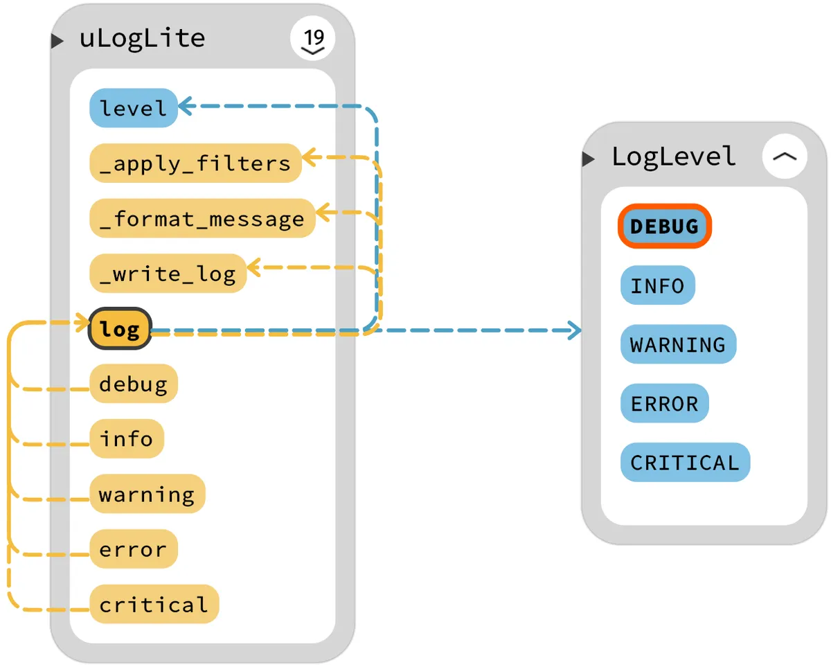
@micropython.native
def log(self, level: int, message: str) -> None:
    """
    Base logging method.

    Args:
        level (int): Log level (use LogLevel enum values)
        message (str): Log content to record

    Returns:
        None

    Raises:
        ValueError: Raised when the log level is invalid or message is empty.
    """
    # Check whether level is an integer and a value in LogLevel
    if not isinstance(level, int) or level not in [getattr(LogLevel, attr) for attr in dir(LogLevel) if
                                                   not attr.startswith('__')]:
        raise TypeError("level must be an integer of LogLevel enum")

    # Check whether message is a string or an empty string
    if not isinstance(message, str) or message == "":
        raise ValueError("message must be a string")

    # Record the log; first check the log level and filters
    if level >= self.level and self._apply_filters(level, message):
        formatted_message = self._format_message(level, message)
        # Output the log according to the settings
        self._write_log(formatted_message)
The log method first checks the log level and filters, then calls the _write_log method to output the formatted and filtered log information:
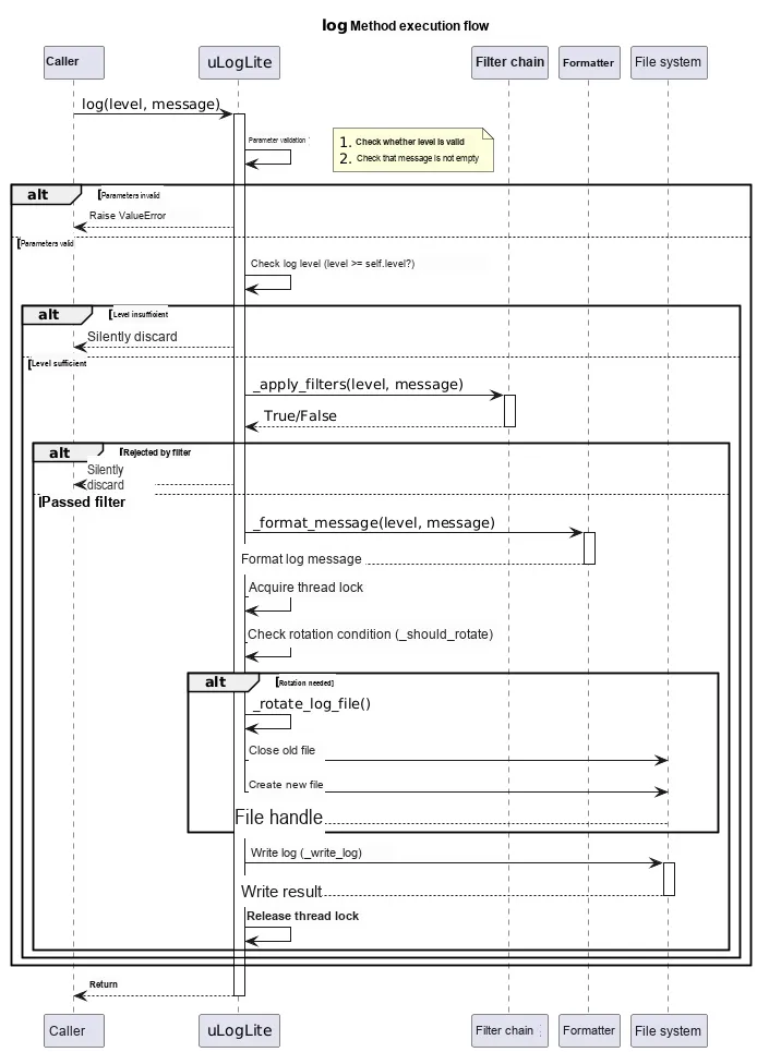
@micropython.native
def _write_log(self, formatted_message: str) -> None:
    """
    Thread-safe log write operation. Choose the write method according to the log output method; it can write to a file or the terminal.

    Execution flow:
        1. Acquire the thread lock
        2. Check the rotation condition
        3. Perform the actual write
        4. Update the counter
        5. Release the lock

    Args:
        formatted_message [str]: The complete formatted log entry.

    Returns:
        None

    Notes:
        - Automatically handles log rotation
        - Falls back to terminal output on write failure
    """

    # Lock the thread to ensure thread safety
    with self.lock:
        # # Record the log write start time
        # start_time = time.ticks_us()

        # Check whether rotation is needed before writing the log
        if self.output != "terminal" and (self.log_count >= self.max_logs or self._should_rotate()):
            # Perform rotation
            self._rotate_log_file()

        # Write log; if file output is set, write to the file, otherwise output to the terminal
        if self.output == "terminal":
            # Output to terminal
            print(formatted_message)
        else:
            # If the file handle is valid, write to the log file
            if self.log_file:
                # Write the message and append a newline
                self.log_file.write(formatted_message + "\n")
                # Flush the log message to the buffer immediately
                self.log_file.flush()
                # Increment the log count counter
                self.log_count += 1

            else:
                # If the file handle is invalid, output to the terminal
                print("can not open file, output to terminal:", formatted_message)

        # # Record the log write end time
        # end_time = time.ticks_us()
        # # Calculate the log write duration
        # # Calculate the elapsed time
        # write_time = time.ticks_diff(end_time, start_time)
        # # Print the elapsed time in ms
        # print(f"write log cost {write_time / 1000} ms")
_write_log () is mainly responsible for writing the formatted log messages to the terminal or a file: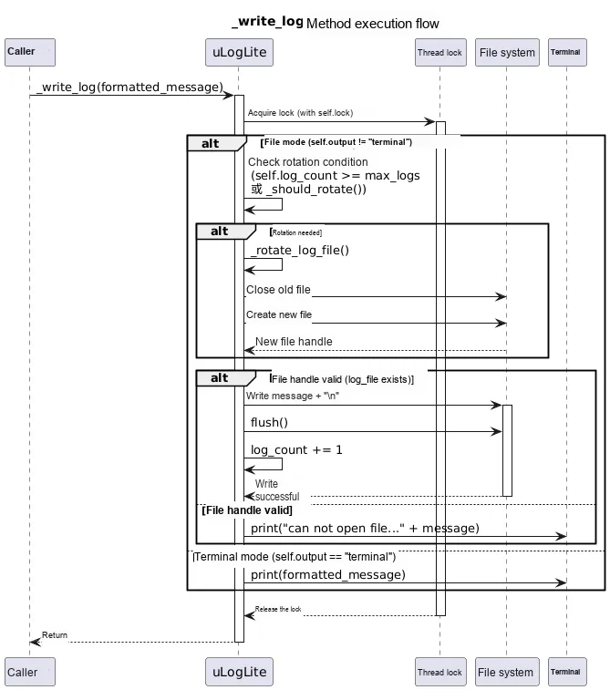
- First, via the lock
self.lock, we ensure that no race condition will occur when multiple threads write logs simultaneously, guaranteeing the atomicity of log writing, and then check whether the log rotation condition is met. - And determine the log output address:
- If the log output method is terminal (
terminal), the log message will be printed directly. - If the log output method is set to file, the log messages will be written to the specified log file.
- If the log output method is terminal (
- If outputting to a file, after ensuring the file handle is valid, write the log message to the file; meanwhile, call the
flush ()method to immediately flush the buffer. Here, increment thelog_countcounter each time a log entry is written;
When checking whether the conditions for log rotation are met, the main check is whether the maximum number of log entries or the log rotation time interval has been reached; if the conditions are satisfied, call the _rotate_log_file () method to close the current log file, open a new log file (by calling the _open_log_file () method), and reset the log entry counter:
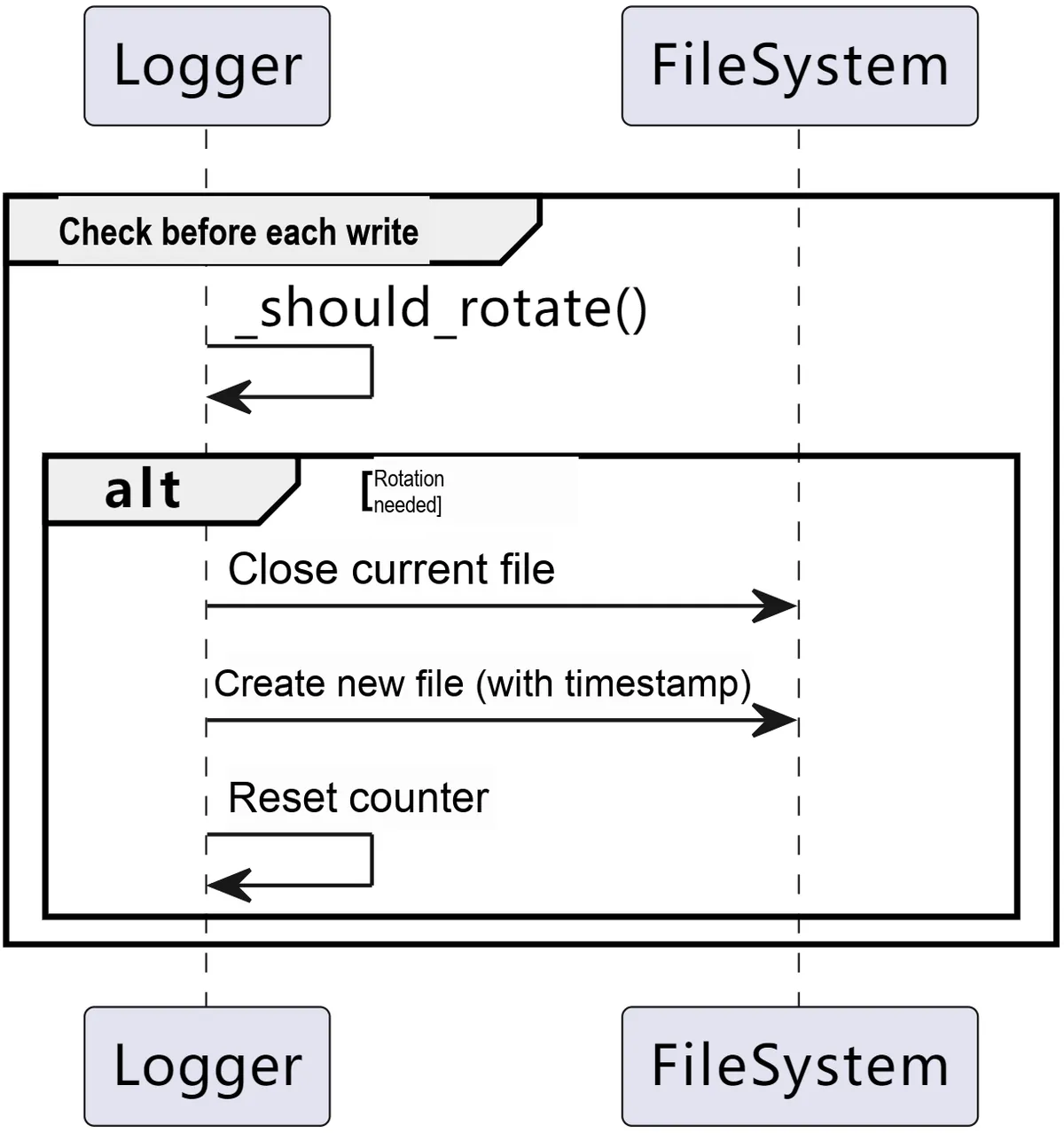
def _rotate_log_file(self) -> None:
    """
    Perform log file rotation, including closing the current file, creating a new file, and resetting the counter.

    Args:
        None

    Returns:
        None

    Raises:
        OSError: Raised when a file operation fails
    """
    # # Debug output
    # print(f"[Rotation] Count:{self.log_count} Max:{self.max_logs}")

    # If the file handle is valid
    if self.log_file:
        # Close the current log file
        self.log_file.close()
    # Open a new log file
    self._open_log_file()
    # Reset the log count counter
    self.log_count = 0
    # Update the last rotation time
    self.last_rotation_time = time.time()

@micropython.native
def _should_rotate(self) -> bool:
    """
    Check whether the log rotation condition is met.

    Args:
        None

    Returns:
        bool: Returns True if rotation is needed, otherwise False
    """
    # Calculate the difference between the last rotation time and the current time
    current_hour = time.localtime()[3]
    last_hour = time.localtime(self.last_rotation_time)[3]
    time_diff = time.time() - self.last_rotation_time

    # The time condition is met if any of the following holds:
    # 1. The interval in hours has been reached
    # 2. The hour has changed and the time difference exceeds 1 hour (handles crossing days)
    return (time_diff >= self.rotate_interval * 3600) or \
        (current_hour != last_hour and time_diff >= 3600)
When invoking the _open_log_file () method, if you select to output logs to a file, we will generate a new log file name based on the current time, open the file in append mode for logging, and the log file name will contain a timestamp:
@micropython.native
def _open_log_file(self) -> None:
    """
    Create/open the log file. If the file already exists, read its line count to initialize the counter; for a new file the counter starts from 0.

    Args:
        None

    Returns:
        None

    Raises:
        OSError: Raised when file creation fails

    Notes:
        - File name format: {name}_{year-month-day_hour-minute-second}.txt
        - Automatically falls back to terminal output on failure
    """
    # Get the current time: format is (year, month, mday, hour, minute, second, weekday, yearday)
    t = time.localtime()
    # Record the timestamp and format it as a year-month-day_hour-minute-second string (e.g., 20240917_143001)
    timestamp = "{:04}{:02}{:02}_{:02}{:02}{:02}".format(t[0], t[1], t[2], t[3], t[4], t[5])

    # If output is to the terminal
    if self.output == "terminal":
        # Set the log file handle to None; terminal mode needs no file operations
        self.log_file = None
        self.log_count = 0
    else:
        # Generate the log file name from the name and timestamp: name_timestamp.txt
        log_filename = f"{self.output}/{self.name}_{timestamp}.txt"

        # Try to create the directory (only single-level directories are handled)
        try:
            os.mkdir(self.output)
        except OSError:
            # Ignore if the directory already exists
            pass

        try:
            # Check whether the file already exists
            try:
                os.stat(log_filename)
                file_exists = True
            except OSError:
                file_exists = False

            # Open the file in append mode (created if it does not exist)
            self.log_file = open(log_filename, 'a')

            # Line count
            if file_exists:
                count = 0
                with open(log_filename, 'r') as f:
                    while True:
                        # Read in 128-byte chunks (suited to memory-constrained environments)
                        chunk = f.read(128)
                        # Reached the end of the file
                        if not chunk:
                            break
                        # Count the newline characters (one per line)
                        count += chunk.count('\n')
                self.log_count = count
            else:
                # If it is a newly created file, initialize the counter
                self.log_count = 0
        except OSError as e:
            # Failed to open the file; print the error message
            print(f"无法打开文件 {log_filename}: {e}")
            # Set the file handle to None
            self.log_file = None
_open_log_file () performs the following operations: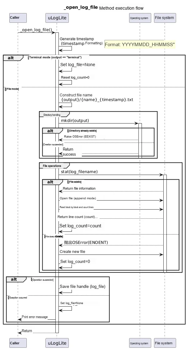
- Record the timestamp and generate a unique log file name:
time.localtime ()gets the current time and returns a tuple containing information such as year, month, day, hour, minute, second, etc.(year, month, mday, hour, minute, second, weekday, yearday), which is formatted via theformat ()method into theYYYYMMDD_HHMMSSformat, for example:20240917_143001. This timestamp is used to generate a unique log file name to avoid file name conflicts. - Terminal output mode and log file mode:
- If the user selects
"terminal"as the log output method, no log file will be created, the log handle will be set toNone, and the log counter will be set to 0 at the same time; - If the user passes in a log file retention path, then combine it with the log storage path
self.output, log nameself.nameand timestamptimestampto concatenate the complete log file name.
- If the user selects
- Processing log files: First, check whether the file exists, then open it in append mode so that logs are appended to the end of the file, while counting the number of log lines and updating
self.log_count. The purpose of counting the number of log lines here is to avoid duplicate numbering in the log rotation mechanism. - Failed to open file for processing: If an
OSErroroccurs (e. g., insufficient storage space, insufficient permissions), print an error message and downgrade to terminal mode (self.log_file = None).
In addition to using debug (), info (), warning (), error (), exception () and other methods to output common log messages, we can also record exception stack information, which is mainly implemented through the exception () method:
def exception(self, exc: Exception, terminal_display: bool = True) -> None:
    """
    Record exception stack trace information.

    Args:
        exc (Exception): Exception object
        terminal_display (bool): Whether to display in the terminal, default is True

    Returns:
        None
    """
    # Print the exception stack trace to the terminal
    if isinstance(exc, Exception):
        # Also write the exception information to the log file
        if self.output != "terminal" and self.log_file:
            sys.print_exception(exc, self.log_file)

        # If the terminal display flag is True, print the exception information to the terminal
        if terminal_display:
            sys.print_exception(exc)
This method will write the stack information of the exception object to the log file at the same time (if the log output mode is set to file and the file handle is valid), and decide whether to display the exception information on the terminal according to the settings;sys.print_exception () method is used to output the detailed exception information to the specified log file or terminal, which not only records the exception information, but also facilitates viewing and debugging on the terminal.
Here, we use a separate LogLevel class instead of defining the log level as a class variable of the Logger class:
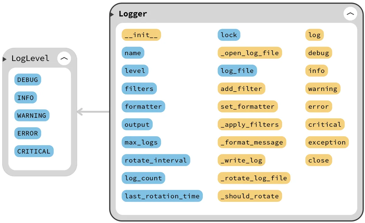
This is primarily for the purposes of separation of duties and enhanced scalability:
- Separation of Responsibilities:
The LogLevelclass is specifically designed to manage log levels and define different log levels (such as DEBUG, INFO, WARNING, etc.), which ensures that the definition of log levels is separated from the behavior logic of the logger, making the code clearer; while theLoggerclass is responsible for functions such as log recording, filtering, and formatting, and does not concern itself with the specific definition of log levels. - Enhance scalability: New log levels (such as
TRACEorFATAL) may need to be added in the future. If log levels are defined as class variables of theLoggerclass, modifying theLoggerclass code will be required when extending log levels. By separating log levels into an independentLogLevelclass, you can more easily extend or modify log levels without affecting the code of theLoggerclass
3.2.2 Key Points for Implementing Log Filters and Log Formatters
To implement the complete logging function, we need the loggers, log filters and log formatters to work together, among which the log filters and log formatters need to be implemented by users themselves:
- Logger: Records, manages and stores events and messages in the system, and supports different log levels (such as
DEBUG,INFO,ERROR, etc.), allows outputting or filtering log messages according to the set level, and also supports the log rotation function (based on time interval or log count), which can output logs to the terminal or a file, and at the same time ensure thread-safe log writing in a multi-threaded environment - Log Filter: A log filter is used to determine which log messages should be recorded. Users can implement different filters according to specific needs, such as filtering log messages by log level, by whether the log contains a keyword, or by the time when the log is created.
- Log Formatter: A log formatter is used to define the output format of log messages. Users can implement different formatters to meet various requirements, such as adding timestamps to log messages or adding different color codes to logs according to their log levels to display different colors on the terminal.
When creating log filters and log formatters, they need to meet specific interface requirements so that they can be properly integrated with the logging system:
- For log filters: a log filter is usually a function or a callable object (a class that implements the
callmethod), whose function is to determine whether a certain log message should be recorded; the filter function or object needs to return a boolean value:Truemeans allowing the log to be recorded,Falsemeans filtering out the log; meanwhile, the filter should receive parameters related to log recording, which at least need to include the log'slevelandmessagetwo parameters. The following are implementations of common filters for log level, log length, time period and keywords:# Log level filter def level_filter(level: int, message: str) -> bool: """ Simple log filter that allows logs of INFO level and above to be recorded Args: level (int): Log level (use LogLevel enum values) message (str): Log message content Returns: bool: True means the log is recorded, False means it is not recorded """ # Simple log filter that only allows logs of INFO level and above to be recorded return level >= LogLevel.INFO # Log length filter def length_filter(max_length: int) -> callable: """ Generate a log length filter function Args: max_length (int): Maximum allowed log length (in bytes) Returns: callable[[int, str], bool]: The generated filter function """ def filter_fn(level, message): return len(message) <= max_length return filter_fn # Time period filter def time_range_filter(start_time: str, end_time: str) -> callable: """ Generate a time period filter function (24-hour format) Args: start_time (str): Start time (format 'HH:MM', e.g. '09:00') end_time (str): End time (format 'HH:MM', e.g. '18:00') Returns: callable[[int, str], bool]: The generated filter function Raises: ValueError: Raised when the time format is invalid """ def filter_fn(level, message): # Get the hour and minute of the current time current_time = time.localtime() current_hour_minute = f"{current_time[3]:02}:{current_time[4]:02}" # Compare whether the current time is within the specified range return start_time <= current_hour_minute <= end_time return filter_fn # Keyword filter def keyword_filter(keywords: list) -> callable: """ Generate a keyword filter function Args: keywords (list[str]): List of keywords that must be included Returns: callable[[int, str], bool]: The generated filter function """ def filter_fn(level, message): # Check whether the log message contains any keyword return any(keyword in message for keyword in keywords) return filter_fnHere, some students may ask: when using a log level filter, we can pass in the
levelandmessageparameters, but why are these two parameters not explicitly defined in the entry parameters of the log level filter function? For example, in theloggerclass's_apply_filtersmethod, the added filter function is called with the following code:def _apply_filters(self, level, message): ''' Apply log filters; if any filter returns False, the log is not recorded :param level [int]: Log level :param message [str]: Log message :return [bool]: True means the log is recorded, False means the log is not recorded ''' # Apply the log filters; if any filter returns False, the log is not recorded for log_filter in self.filters: if not log_filter(level, message): return False return TrueThis is because the log level filter function uses the closure feature. A closure refers to a function defined inside an outer function (here, the filter function) — specifically the internally defined
filter_fnfunction — and the inner function can access the variables of the outer function even after the outer function's scope has ended. Simply put, when we add a filter, we use the following statement:# Filter out logs longer than 50 characters logger.add_filter(length_filter(50)) # Filter out logs that do not contain the 'FreakStudio' keyword logger.add_filter(keyword_filter(["FreakStudio"]))Here, in fact, we only call the external log filter function and pass the specific parameters required by the log filter function (such as keywords and maximum log length), without executing the internal
filter_fnfunction: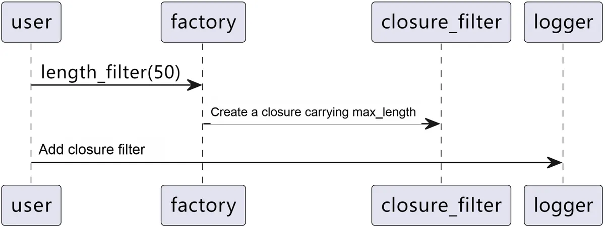
The execution result returns the internal
filter_fnfunction, which is also passed via theadd_filtermethod to theloggerclass instance's correspondingself.filterslist of filter functions:def add_filter(self, log_filter): ''' Add a log filter :param log_filter [function]: Log filter :return: None ''' # Add the log filter self.filters.append(log_filter)It is only when
the _apply_filtersapply filter method uses thelog_filter (level, message)statement that the internalfilter_fnfunction is actually called, with thelevelandmessageparameters passed in.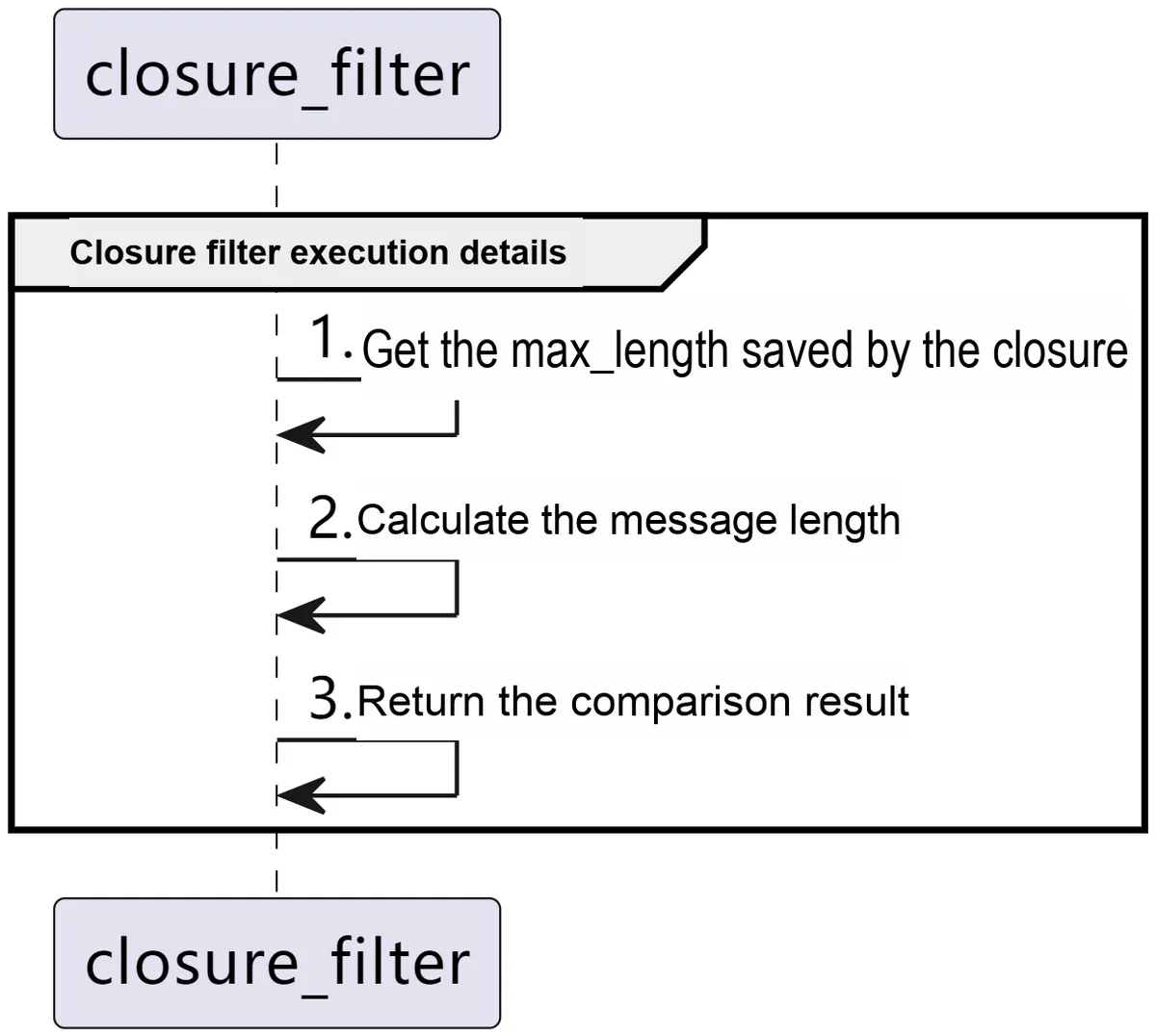
At this point, internally
filter_fnserves as the concrete implementation of each filter function, which ultimately returns a boolean value ofTrueorFalseto control whether the log passes the filtering.The Sequence Diagram of the aforementioned calls is shown below:
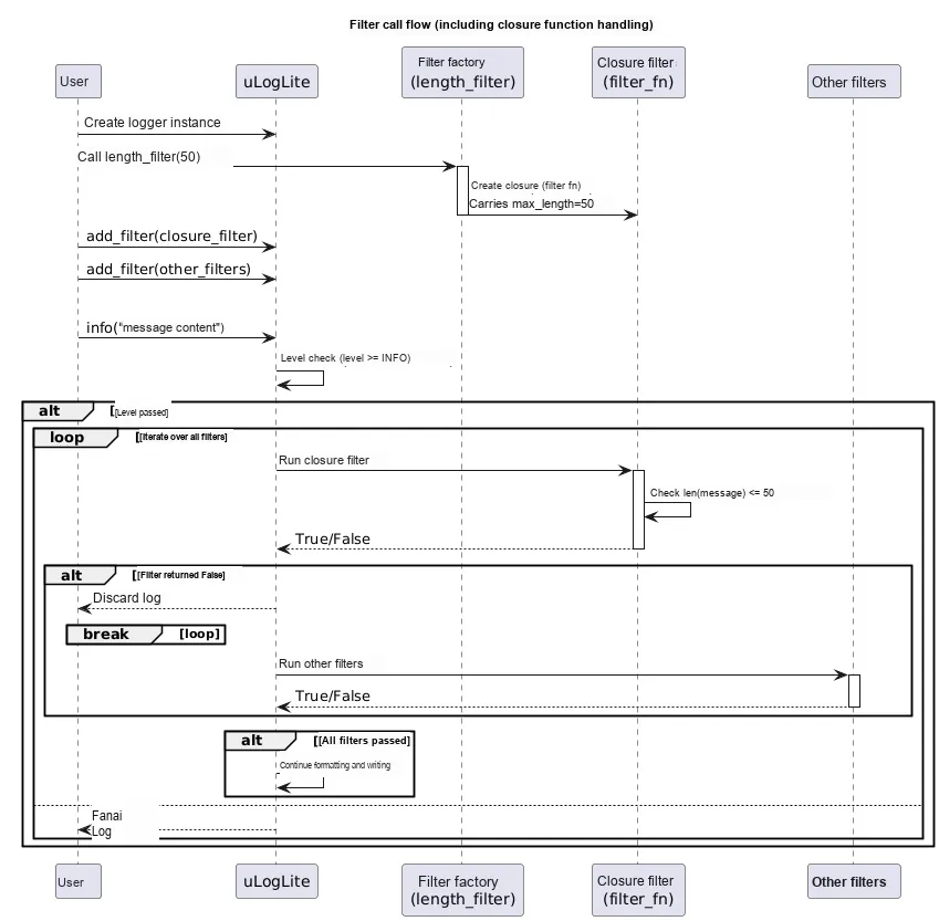
In this way, each filter focuses on a specific type of filtering rules, such as filtering the level, length, time range of logs, or whether they contain specific keywords. This Modularization design allows multiple filters to be used in combination, improving the flexibility and maintainability of the code.
- For a log formatter, it is generally a class and must provide a formatting method (i. e. the
formatmethod) that accepts log information such as thelevelandmessage, and returns a formatted string. For example, in the following code, we implement a simple formatter that outputs the timestamp and the message:class TimeMessageFormatter: """ Time and message formatter class that provides concise log formatting This class formats log messages into a fixed format: "YYYY-MM-DD HH:MM:SS - message", ignoring log level information, suitable for scenarios that need simplified log output. Attributes: None Methods: format(level, message): Core formatting method that generates a log message with a timestamp """ def format(self, level: int, message: str) -> str: """ Format the log message and generate an output string with a timestamp Args: level (int): Log level (unused, kept for interface consistency) message (str): Original log content Returns: str: Formatted log message, in the format: "YYYY-MM-DD HH:MM:SS - message" Notes: - The timestamp uses local time - The log level parameter is ignored (kept for interface compatibility) - The returned string does not contain a newline """ # Get the local time tuple of the current time local_time = time.localtime() # Construct an ISO 8601 format time string (YYYY-MM-DD HH:MM:SS) current_time = "{:04}-{:02}-{:02} {:02}:{:02}:{:02}".format( local_time[0], # Year (4 digits) local_time[1], # Month (01-12) local_time[2], # Day (01-31) local_time[3], # Hour (00-23) local_time[4], # Minute (00-59) local_time[5] # Second (00-59) ) # Return the formatted message (does not include log level information) return f"{current_time} - {message}"
3.2.2 Application Experiment of Logging Class
In the following code, a custom logging module is used to implement logging, filtering and rotation functions in the MicroPython environment; the logged content is controlled via log levels, length and keyword filters, and a color formatter is used to enhance log readability; the code also demonstrates how to handle and log exception stack information.
The following code can be found in the elegance-devkit v1\Demo\71 FileSys_Logger folder in the resource package we provide.
The sample code is shown below:
# Python env : MicroPython v1.23.0
# -*- coding: utf-8 -*-
# @Time : 2024/9/16 2:40 PM
# @Author : Li Qingshui
# @File : main.py
# @Description : File system experiment, using the logger module to implement logging
# ======================================== Import Modules =========================================
# Import the logging module
from logger import uLogLite, LogLevel
# Import the os module, used for file operations
import os
# Import time-related modules
import time
# Import hardware-related modules
import machine
# ======================================== Global Variables ============================================
# Define the file path for storing log data
logfile_path = "/logs"
# Create the log file directory
os.mkdir(logfile_path)
# ======================================== Functions ============================================
# Log level filter
def level_filter(level: int, message: str) -> bool:
    """
    Simple log filter that allows logs of INFO level and above to be recorded

    Args:
        level (int): Log level (use LogLevel enum values)
        message (str): Log message content

    Returns:
        bool: True means the log is recorded, False means it is not recorded
    """

    # Simple log filter that only allows logs of INFO level and above to be recorded
    return level >= LogLevel.INFO

# Log length filter
def length_filter(max_length: int) -> callable:
    """
    Generate a log length filter function

    Args:
        max_length (int): Maximum allowed log length (in bytes)

    Returns:
        callable[[int, str], bool]: The generated filter function
    """
    def filter_fn(level, message):
        return len(message) <= max_length
    return filter_fn

# Time period filter
def time_range_filter(start_time: str, end_time: str) -> callable:
    """
    Generate a time period filter function (24-hour format)

    Args:
        start_time (str): Start time (format 'HH:MM', e.g. '09:00')
        end_time (str): End time (format 'HH:MM', e.g. '18:00')

    Returns:
        callable[[int, str], bool]: The generated filter function

    Raises:
        ValueError: Raised when the time format is invalid
    """
    def filter_fn(level, message):
        # Get the hour and minute of the current time
        current_time = time.localtime()
        current_hour_minute = f"{current_time[3]:02}:{current_time[4]:02}"
        # Compare whether the current time is within the specified range
        return start_time <= current_hour_minute <= end_time
    return filter_fn

# Keyword filter
def keyword_filter(keywords: list) -> callable:
    """
    Generate a keyword filter function

    Args:
        keywords (list[str]): List of keywords that must be included

    Returns:
        callable[[int, str], bool]: The generated filter function
    """
    def filter_fn(level, message):
        # Check whether the log message contains any keyword
        return any(keyword in message for keyword in keywords)
    return filter_fn
# Print all .txt files in the directory
def print_txt_files_in_directory(directory: str) -> None:
"""
Traverse and print the contents of all .txt files in the directory
Args:
directory (str): Path of the directory to traverse
Returns:
None
Raises:
OSError: Raised when directory access fails
"""
try:
# List all files and subdirectories in the directory
files = os.listdir(directory)
# Traverse all files in the directory
for file in files:
# Check whether the file ends with .txt
if file.endswith('.txt'):
# Print the file name
file_path = directory + '/' + file
print(f"Reading file: {file_path}")
try:
# Open and read the file
with open(file_path, 'r') as f:
# Read the file content line by line and print it
for line in f:
# end='' prevents automatic newline
print(line, end='')
except OSError as e:
print(f"Error reading file {file_path}: {e}")
# Print an empty line to separate file contents
print()
except OSError as e:
print(f"Error listing directory {directory}: {e}")
# ======================================== Custom Classes ============================================
# Terminal color formatter
class ColoredFormatter:
"""
Terminal color formatter class that adds ANSI color control characters and a timestamp to log messages.
This class automatically adds ANSI escape sequences of different colors to messages according to the log level, and adds a standardized timestamp.
Supports color customization for all standard log levels (DEBUG/INFO/WARNING/ERROR/CRITICAL).
Attributes:
COLORS (dict): Color code mapping table, including:
- LogLevel.DEBUG: blue
- LogLevel.INFO: green
- LogLevel.WARNING: yellow
- LogLevel.ERROR: red
- LogLevel.CRITICAL: red background
- "ENDC": color reset code
Methods:
format(level, message):
Core formatting method, adds color and timestamp
"""
# Define color codes
COLORS = {
LogLevel.DEBUG: '\033[94m', # Blue
LogLevel.INFO: '\033[92m', # Green
LogLevel.WARNING: '\033[93m', # Yellow
LogLevel.ERROR: '\033[91m', # Red
LogLevel.CRITICAL: '\033[41m', # Red background
"ENDC": '\033[0m' # Reset color
}
def format(self, level: int, message: str) -> str:
"""
Format the log message, adding a timestamp and color control characters
Args:
level (int): Log level (use LogLevel enum values)
message (str): Original log content
Returns:
str: Formatted log message, including:
- Color control characters (according to log level)
- Timestamp (YYYY-MM-DD HH:MM:SS format)
- Log level and original message
Raises:
ValueError: May be raised when the log level is invalid
Notes:
- Color control follows ANSI escape sequences
- Timestamp uses UTC time
- Unrecognized log levels use the default color
"""
# Get the local time tuple of the current time
local_time = time.localtime()
# Build ISO 8601 format time string (YYYY-MM-DD HH:MM:SS)
timestamp = "{:04}-{:02}-{:02} {:02}:{:02}:{:02}".format(
local_time[0], # Year (4 digits)
local_time[1], # Month (01-12)
local_time[2], # Day (01-31)
local_time[3], # Hour (00-23)
local_time[4], # Minute (00-59)
local_time[5] # Second (00-59)
)
# Get the color code for the corresponding level, default to ENDC (reset color)
color = self.COLORS.get(level, self.COLORS["ENDC"])
# Return the formatted message with color, reset color at the end
return f"{color} [log]: {timestamp} - {level}: {message}{self.COLORS['ENDC']}"
# ======================================== Initialization ==========================================
# Power-on delay of 3 s
time.sleep(3)
# Print debug information
print("FreakStudio : Using logger module to save status of system")
# Create RTC object
rtc = machine.RTC()
# Set the RTC time to modify the system's internal time; time can also be obtained from an NTP server
# Set the system time to September 17, 2024, 14:40:00
rtc.datetime((2024, 9, 17, 0, 14, 40, 0, 0))
# Create a log object: log name is "MyLogger", log level is INFO, output to file, maximum number of logs is 20
# If the number of logs exceeds 20, a new file will be created
logger = uLogLite("MyLogger", LogLevel.INFO, logfile_path, max_logs=20)
# Add multiple filters
# Filter out logs below the INFO notice level
logger.add_filter(level_filter)
# Filter out logs longer than 50 characters
logger.add_filter(length_filter(50))
# Filter out logs that do not contain the 'FreakStudio' keyword
logger.add_filter(keyword_filter(["FreakStudio"]))
# Set to use the colored terminal formatter
logger.set_formatter(ColoredFormatter())
# ======================================== Main Program ===========================================
# Test the logging module
print("Test logger module output log")
# Record debug information; this log will not be recorded because of the log level filter
logger.debug("FreakStudio : This is a debug message")
# Delay 30 ms
time.sleep_ms(30)
# Record an info log
logger.info("FreakStudio : This is an info message")
# This log will not be recorded because of the log length filter
logger.info("FreakStudio : This is a very very long long long long long info message,"
"and the length is more than 50")
# Delay 30 ms
time.sleep_ms(30)
# Record a warning log
logger.warning("FreakStudio : This is a warning message")
# This log will not be recorded because of the log keyword filter
logger.warning("This is a warning message")
# Delay 30 ms
time.sleep_ms(30)
# Record an error log
logger.error("FreakStudio : This is an error message")
# Delay 30 ms
time.sleep_ms(30)
# Record a critical error log
logger.critical("FreakStudio : This is a critical message")
# Delay 30 ms
time.sleep_ms(30)
# Test the log rotation function
print("Test logger rotate log file")
# Record 100 logs in a loop to test the log rotation function
for i in range(20):
# Record a debug log
logger.debug(f"FreakStudio : This is a debug message {i}")
time.sleep_ms(100)
# Record an info log
logger.info(f"FreakStudio : This is an info message {i}")
time.sleep_ms(100)
# Record a warning log
logger.warning(f"FreakStudio : This is a warning message {i}")
time.sleep_ms(100)
# Record an error log
logger.error(f"FreakStudio : This is an error message {i}")
time.sleep_ms(100)
# Record a critical error log
logger.critical(f"FreakStudio : This is a critical message {i}")
time.sleep_ms(100)
# Test the function of recording exception stack information in the log
print("Test logger record exception stack")
# Deliberately raise an exception
try:
1 / 0
except Exception as e:
# Record exception stack information and display it in the terminal at the same time
logger.exception(e, terminal_display=True)
# Close the log file
logger.close()
# Output debug information
print("FreakStudio : logging file write done")In the above code, we follow the process outlined below:
- Create a logger
Loggerobjectloggerthat can record log information at different levels, such as debug, info, warning, error and critical error. It is configured with a maximum number of 20 logs, and here we set the log file storage path to thelogfolder under the root directory. - The logger is configured with multiple filters and a colored formatter to control the content and format of the logged messages.
- Log Filter:
- Level Filter
level_filter: Only logs at theINFOlevel and above will be recorded. - Length Filter
length_filter: Only logs with a length of no more than 50 characters will be recorded. - Keyword Filter
keyword_filter: Only logs containing the keyword "FreakStudio" will be recorded.
- Level Filter
- Log Formatter: Used to format log messages and add colors to distinguish different log levels in the terminal.
- Log Filter:
- Create an
RTCobject and set the internal system time. - Print debug information to test the logging function:
- Record log messages at various levels to verify the operation of filters and formatters.
- Test the log rotation function by cyclically recording multiple logs to trigger log rotation.
- Record exception stack information, simulate throwing an exception and record the exception information.
- Close the log file.
Here, we define a ColoredFormatter class to add colors to log messages for better readability in the terminal:
# Terminal color formatter
class ColoredFormatter:
    """
    Terminal color formatter class that adds ANSI color control characters and a timestamp to log messages.

    This class automatically adds ANSI escape sequences of different colors to messages according to the log level, and adds a standardized timestamp.
    Supports color customization for all standard log levels (DEBUG/INFO/WARNING/ERROR/CRITICAL).

    Attributes:
        COLORS (dict): Color code mapping table, including:
            - LogLevel.DEBUG: blue
            - LogLevel.INFO: green
            - LogLevel.WARNING: yellow
            - LogLevel.ERROR: red
            - LogLevel.CRITICAL: red background
            - "ENDC": color reset code

    Methods:
        format(level, message):
            Core formatting method, adds color and timestamp
    """
    # Define color codes
    COLORS = {
        LogLevel.DEBUG: '\033[94m',     # Blue
        LogLevel.INFO: '\033[92m',      # Green
        LogLevel.WARNING: '\033[93m',   # Yellow
        LogLevel.ERROR: '\033[91m',     # Red
        LogLevel.CRITICAL: '\033[41m',  # Red background
        "ENDC": '\033[0m'               # Reset color
    }

    def format(self, level: int, message: str) -> str:
        """
        Format the log message, adding a timestamp and color control characters

        Args:
            level (int): Log level (use LogLevel enum values)
            message (str): Original log content

        Returns:
            str: Formatted log message, including:
                 - Color control characters (according to log level)
                 - Timestamp (YYYY-MM-DD HH:MM:SS format)
                 - Log level and original message

        Raises:
            ValueError: May be raised when the log level is invalid

        Notes:
            - Color control follows ANSI escape sequences
            - Timestamp uses UTC time
            - Unrecognized log levels use the default color
        """
        # Get the local time tuple of the current time
        local_time = time.localtime()

        # Build ISO 8601 format time string (YYYY-MM-DD HH:MM:SS)
        timestamp = "{:04}-{:02}-{:02} {:02}:{:02}:{:02}".format(
            local_time[0],  # Year (4 digits)
            local_time[1],  # Month (01-12)
            local_time[2],  # Day (01-31)
            local_time[3],  # Hour (00-23)
            local_time[4],  # Minute (00-59)
            local_time[5]  # Second (00-59)
        )

        # Get the color code for the corresponding level, default to ENDC (reset color)
        color = self.COLORS.get(level, self.COLORS["ENDC"])
        # Return the formatted message with color, reset color at the end
        return f"{color} [log]: {timestamp} - {level}: {message}{self.COLORS['ENDC']}"
Among them, COLORS is a dictionary that defines the terminal color codes corresponding to different log levels:
\033[94m: Blue, used for theDEBUGlevel.\033[92m: Green, used forINFOlevel.\033[93m: Yellow, used forWARNINGlevel.\033[91m: Red, used for theERRORlevel.\033[41m: Red background, used forCRITICALlevel.\033[0m: Reset the color, used to restore the default color.
Here, the different colors displayed in the terminal are achieved by using ANSI escape codes, which are the standard mechanism for controlling terminal text styles including effects like color, bold, underline, etc. : An ANSI escape code is a special character sequence that tells the terminal how to display text; it starts with \033 (or \e), followed by a square bracket[and a series of parameters, and ends with a letter.
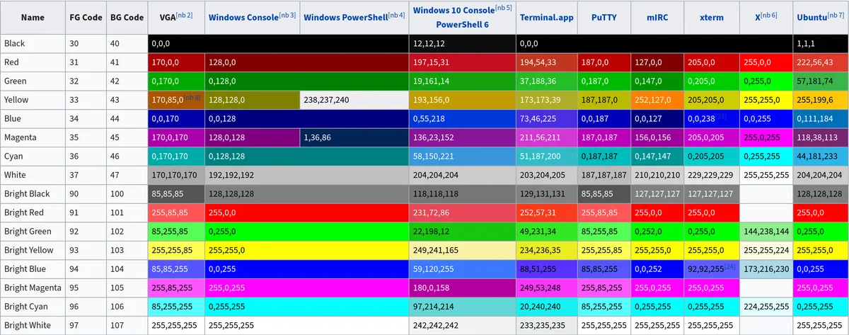
In the format method for formatting log messages, we first obtain the current local time tuple, and then format the time tuple as a string in the format of YYYY-MM-DD HH: MM: SS , which represents the time of logging.
In the code for color selection and message construction:
    # Select color according to log level
    color = self.COLORS.get(level, self.COLORS["ENDC"])
    # Return the formatted message with color
    return f"{color} [log]: {timestamp} - {level}: {message}{self.COLORS['ENDC']}"
We retrieve the corresponding color code from the COLORS dictionary based on the log level; if the level is not defined in the dictionary, we use ENDC as the default value. We then construct the final log message, which includes the timestamp, log level, and log content, wrapped with the color code, and finally append ENDC at the end of the log message to reset the color.
Finally, we also define a function that is used to traverse all files with the. txt suffix in the specified directory and print the content of the files line by line:
# Print all .txt files in the directory
def print_txt_files_in_directory(directory: str) -> None:
    """
    Traverse and print the contents of all .txt files in the directory

    Args:
        directory (str): Path of the directory to traverse

    Returns:
        None

    Raises:
        OSError: Raised when directory access fails
    """
    try:
        # List all files and subdirectories in the directory
        files = os.listdir(directory)

        # Traverse all files in the directory
        for file in files:
            # Check whether the file ends with .txt
            if file.endswith('.txt'):
                # Print the file name
                file_path = directory + '/' + file
                print(f"Reading file: {file_path}")

                try:
                    # Open and read the file
                    with open(file_path, 'r') as f:
                        # Read the file content line by line and print it
                        for line in f:
                            # end='' prevents automatic newline
                            print(line, end='')
                except OSError as e:
                    print(f"Error reading file {file_path}: {e}")
                # Print an empty line to separate file contents
                print()
    except OSError as e:
        print(f"Error listing directory {directory}: {e}")
The function accepts a parameter directory, which indicates the directory to be traversed. First, we use os.listdir (directory) to list all files and subdirectories in the specified directory, then iterate over each entry in the files list, check the file suffix, process. txt files, and read the file content line by line.
The entire process of the system is shown in the following figure:
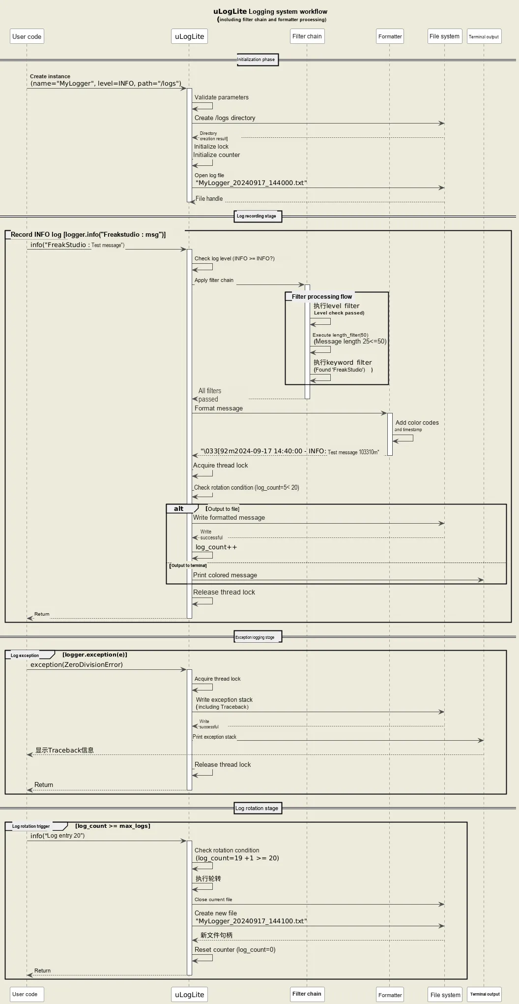
Burn the code, open the terminal, and the output is as follows:
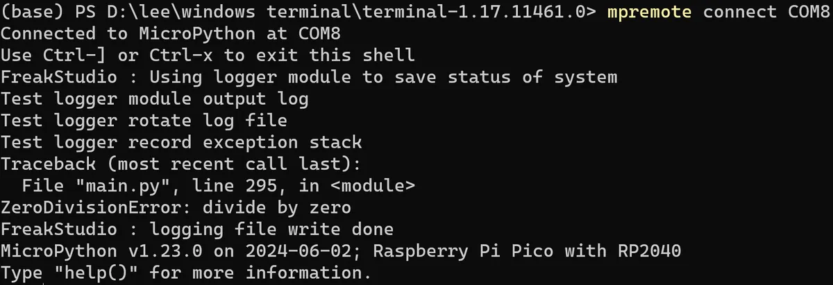
As you can see, after the log file is fully written, we use the os.listdir (logfile_path) command to check the files in the current directory:

Display multiple files with timestamps in their names, then call the print_txt_files_in_directory function to view the file contents:
print_txt_files_in_directory(logfile_path)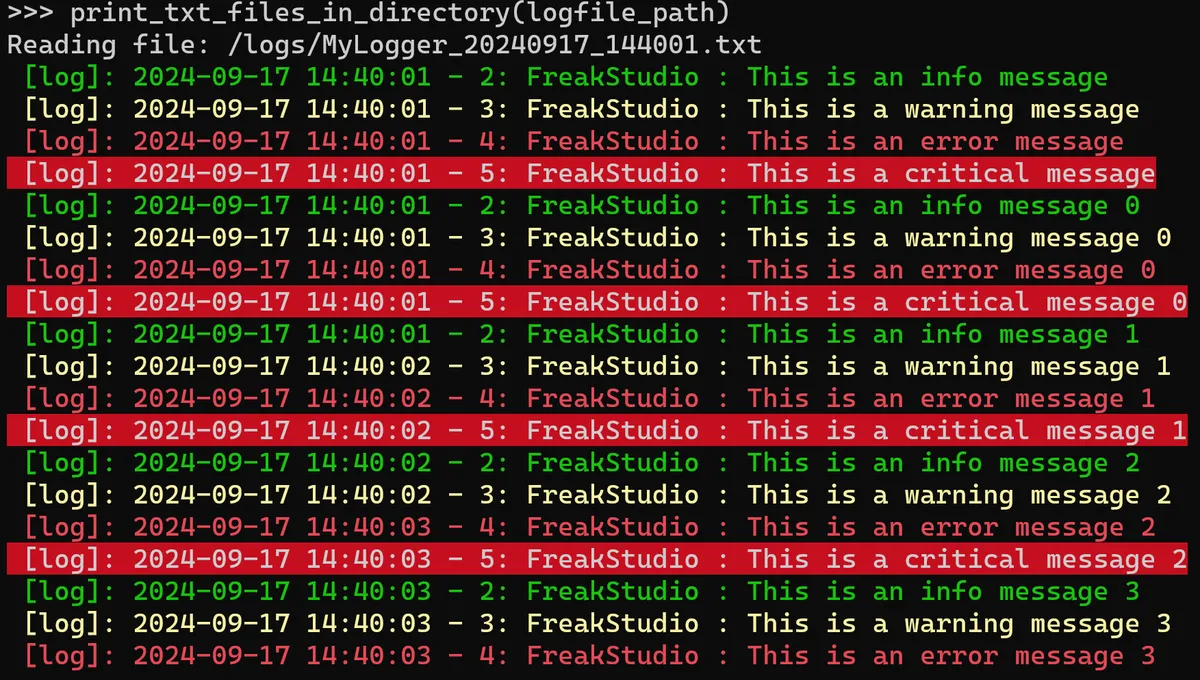
It can be seen that the log filter functions properly, and none of the following logs have been recorded:
# Record debug information; this log will not be recorded because of the log level filter
logger.debug("FreakStudio : This is a debug message")
# This log will not be recorded because of the log length filter
logger.info("FreakStudio : This is a very very long long long long long info message,"
            "and the length is more than 50")
# This log will not be recorded because of the log keyword filter
logger.warning("This is a warning message")
Among the multiple logs recorded subsequently, they are stored in separate files:
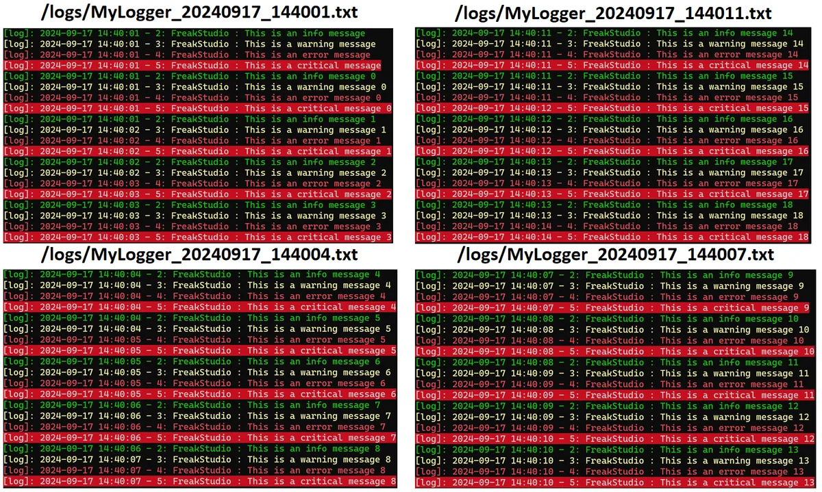
As can be seen, the exception stack information is also recorded in the file:
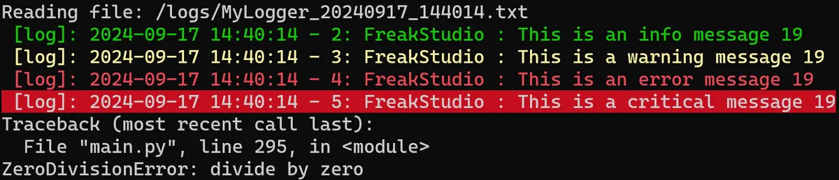
3.2 Application Experiment.mp4 19.8 MB
It should be noted here that in the custom logger class, we write to the log file in append mode. As the file grows larger, the file system needs more time to locate the end of the file and perform the write operation. Therefore, in the logger class's _write_log method, we add code to calculate the time consumption:
@micropython.native
def _write_log(self, formatted_message: str) -> None:
    """
    Thread-safe log write operation. Choose the write method according to the log output method; it can write to a file or the terminal.

    Execution flow:
        1. Acquire the thread lock
        2. Check the rotation condition
        3. Perform the actual write
        4. Update the counter
        5. Release the lock

    Args:
        formatted_message [str]: The complete formatted log entry.

    Returns:
        None

    Notes:
        - Automatically handles log rotation
        - Falls back to terminal output on write failure
    """

    # Lock the thread to ensure thread safety
    with self.lock:
        # Record the log write start time
        start_time = time.ticks_us()

        ... ...

        # Record the log write end time
        end_time = time.ticks_us()
        # Calculate the time taken to write the log
        # Calculate elapsed time
        write_time = time.ticks_diff(end_time, start_time)
        # Print the elapsed time, in ms
        print(f"write log cost {write_time / 1000} ms")
Clear all files on the Raspberry Pi Pico, flash the code, and open the terminal:
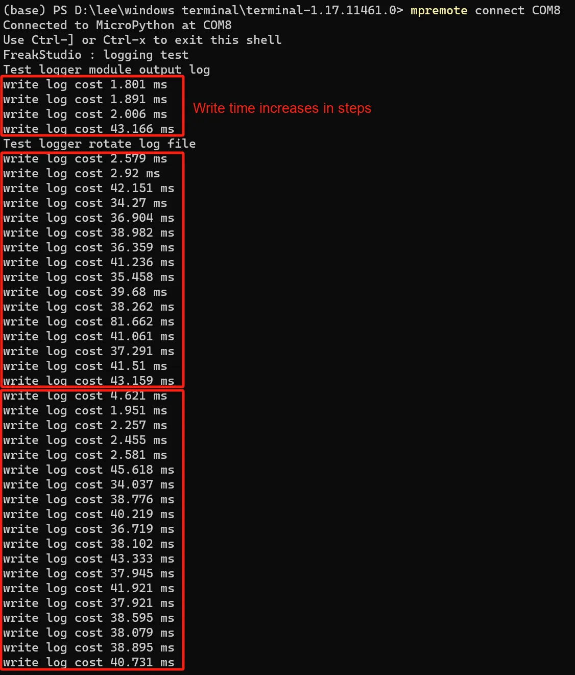
It can be seen that the write time increases in stages, and the time consumption will also increase when a new file needs to be created.
Meanwhile, we can also use the os.stat ('/logs/MyLogger_20240917_144011.txt') command to check the file-related information:

>>> os.stat('/logs/MyLogger_20240917_144011.txt')
(32768, 0, 0, 0, 0, 0, 1690, 1726584014, 1726584014, 1726584014)
Here, the output information includes (mode, ino, dev, nlink, uid, gid, size, atime, mtime, ctime):
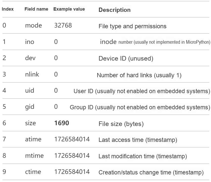
Here, apart from the filter functions and formatter classes we have implemented above, you can also define specific filter functions as needed, and please note the following at this point:
- Flexibility of Filtering Rules: The log filter shall support filtering based on multiple criteria, including but not limited to log level, keywords, time range, message length, device ID, session ID, etc.
- Interface Consistency: Log filters shall feature consistent interfaces to facilitate integration and extension
- Composability: A logging system should allow multiple filters to work in combination, meaning that a log message can only be recorded after passing the checks of all filters, and such filters should be composable.
When customizing a formatter, it should be noted that apart from terminal formats with colors, the log formatter should support multiple output formats, and common formatting methods include:
- JSON format: Structured logs that are easy for machines to parse and process
- Simple text format: output log level, timestamp, and message
- Custom Format: Supports more complex formats as required by users (e. g., incorporating device ID, session ID, etc.)
Compared to the logging module of MicroPython, our custom logger class also provides core logging functions, including log levels, formatting, handlers (terminal and file), and exception handling; it also implements a thread-safe mechanism and supports log file rotation. However, the logging module of MicroPython offers more features and extensibility, such as more options for Filter and Handler, making it suitable for more complex logging requirements.
3.3 Implementation of the Simple Block Device Class
3.3.1 Implementation of the Abstract Base Class for Block Devices
As we mentioned earlier, MicroPython does not provide a built-in method for operating block devices, but it offers an abstract block device interface class. For our custom block device operation class to work properly, it needs to conform to the interfaces defined in the vfs.AbstractBlockDev abstract class, so as to enable file and storage device operations within the Virtual File System (VFS).
Below is a simple implementation example of a RAM block device (not recommended for practical use, for demonstration only):
class RAMBlockDev:
    def __init__(self, block_size, num_blocks):
        self.block_size = block_size
        self.data = bytearray(block_size * num_blocks)

    def readblocks(self, block_num, buf):
        for i in range(len(buf)):
            buf[i] = self.data[block_num * self.block_size + i]

    def writeblocks(self, block_num, buf):
        for i in range(len(buf)):
            self.data[block_num * self.block_size + i] = buf[i]

    def ioctl(self, op, arg):
        if op == 4:  # Get the number of blocks
            return len(self.data) // self.block_size
        if op == 5:  # Get the block size
            return self.block_size
Here, vfs.AbstractBlockDev is an abstract base class that defines the basic interfaces a block device should implement. Any custom block device class must implement these methods to be used for file system operations (such as littlefs, fatfs, etc.) via the VFS.While the RAMBlockDev class is a concrete implementation that inherits the interface of vfs.AbstractBlockDev, representing a block device that uses memory as the storage medium. It simulates the behavior of read and write operations on a block device, and provides the corresponding ioctl implementation for methods to obtain information such as the size and number of blocks of the block device.
In the following sample code, we first create a AbstractBlockDevInterface.py file to hold the abstract base class:
# Python env   : MicroPython v1.23.0
# -*- coding: utf-8 -*-
# @Time    : 2024/9/18 PM 12:15
# @Author  : Li Qingshui
# @File    : AbstractBlockDevInterface.py.py
# @Description : Defines the abstract base class AbstractBlockDev for block devices

# ======================================== Import Modules =========================================

# ======================================== Global Variables ============================================

# ======================================== Functions ============================================

# ======================================== Custom Classes ============================================

# Custom abstract base class AbstractBlockDev, representing the basic operation interface of a block device
class AbstractBlockDev:
    """
    AbstractBlockDev class, defines a block device operation interface conforming to the MicroPython specification.

    This class provides an abstract interface for block devices, supporting a simple interface (block-aligned operations) and an extended interface (arbitrary-offset operations),
    and is compatible with the driver requirements of MicroPython filesystems (such as FAT and littlefs). Implementers must support at least
    ioctl(4) block count query; to support littlefs, the ioctl(6) block erase function must also be implemented.

    Attributes:
        (The following attributes are implemented by concrete subclasses)
        block_size (int): Block size (in bytes), usually exposed through ioctl(5)
        block_count (int): Total number of blocks, usually exposed through ioctl(4)

    Methods:
        __init__():
            Initialize the block device abstract base class
        readblocks(block_num, buf, offset=0):
            Read data blocks from the device into a buffer
        writeblocks(block_num, buf, offset=0):
            Write data to the device or erase blocks
        ioctl(op, arg):
            Control device operations and query parameters

    Note:
        - Simple interface: requires the buffer length to be aligned with the block size (offset=0)
        - Extended interface: supports arbitrary offset and length (offset≠0)
        - The following must be observed when writing:
            - The simple interface must handle erasing automatically
            - The extended interface prohibits implicit erasing
    """
    # Standard opcode constants (class attributes)
    IOCTL_INIT = 1      # Device initialization
    IOCTL_SHUTDOWN = 2  # Device shutdown
    IOCTL_SYNC = 3      # Data synchronization
    IOCTL_BLK_COUNT = 4 # Get block count (must be implemented)
    IOCTL_BLK_SIZE = 5  # Get block size (optional)
    IOCTL_BLK_ERASE = 6 # Block erase (required by littlefs)

    def __init__(self) -> None:
        """
        Initialize the block device abstract base class.

        Args:
            None

        Returns:
            None

        Note:
            - Must support at least ioctl(4) to get the block count
            - Implementing littlefs requires additional support for ioctl(6) block erase
        """
        pass

    def readblocks(self, block_num: int, buf: bytearray, offset: int = 0) -> None:
        """
        Read data blocks from the device into a buffer.

        Args:
            block_num (int): Starting block number (starting from 0).
            buf (bytearray): Buffer to store the read data.
            offset (int, optional): Byte offset within the block (default 0 means full block read).

        Returns:
            None

        Raises:
            OSError: If block_num is invalid (ENODEV).
            OSError: If the read fails (EIO).
            NotImplementedError: If the extended interface is not implemented (when offset≠0).
        """
        raise NotImplementedError("sub class must implement this method")

    def writeblocks(self, block_num: int, buf: bytearray | None, offset: int = 0) -> None:
        """
        Write data to the block device.

        Args:
            block_num (int): Target block number (starting from 0)
            buf (bytearray | None): Data to write (None means erase the block)
            offset (int, optional): Byte offset within the block (default 0 means full block write)

        Returns:
            None

        Raises:
            OSError: If block_num is invalid (ENODEV)
            OSError: If the write fails (EIO)
            OSError: If the device is read-only (EROFS)
            NotImplementedError: If the extended interface is not implemented (when offset≠0)
        """
        raise NotImplementedError("sub class must implement this method")

    def ioctl(self, op: int, arg: int) -> int | None:
        """
        Device control operation.

        Args:
            op (int): Opcode (class constants should be used):
                - `AbstractBlockDev.IOCTL_INIT` (1)       : Device initialization
                - `AbstractBlockDev.IOCTL_SHUTDOWN` (2)   : Device shutdown
                - `AbstractBlockDev.IOCTL_SYNC` (3)       : Data synchronization
                - `AbstractBlockDev.IOCTL_BLK_COUNT` (4)  : Get the total number of blocks of the device (must be implemented)
                - `AbstractBlockDev.IOCTL_BLK_SIZE` (5)   : Get the block size (optional)
                - `AbstractBlockDev.IOCTL_BLK_ERASE` (6)  : Erase block (required by littlefs)

            arg (int): Operation argument (depends on op); some operations need no argument:
                - `IOCTL_BLK_ERASE` (6) requires the block number to erase to be passed in
                - Other operations can pass `0` or `None`, as defined by the subclass

        Returns:
            int | None:
                - `IOCTL_BLK_COUNT` (4): Returns the total number of blocks of the device (int)
                - `IOCTL_BLK_SIZE` (5) : Returns the block size (int)
                - `IOCTL_BLK_ERASE` (6): Returns `0` on successful erase
                - Other operations return `None` by default

        Raises:
            NotImplementedError: If the subclass does not implement this method
        """
        raise NotImplementedError("sub class must implement this method")

# ======================================== Initialization ==========================================

# ========================================  Main Program  ===========================================
The purpose of this type of design is to unify the operation methods of different storage media (such as Flash, RAM, SD card, etc.), support the underlying driver requirements of file systems including FAT and littlefs, and provide both simple interfaces (block-aligned) and extended interfaces (arbitrary offset).
Here, we follow the method specified in the official documentation to define the vfs.AbstractBlockDev class:
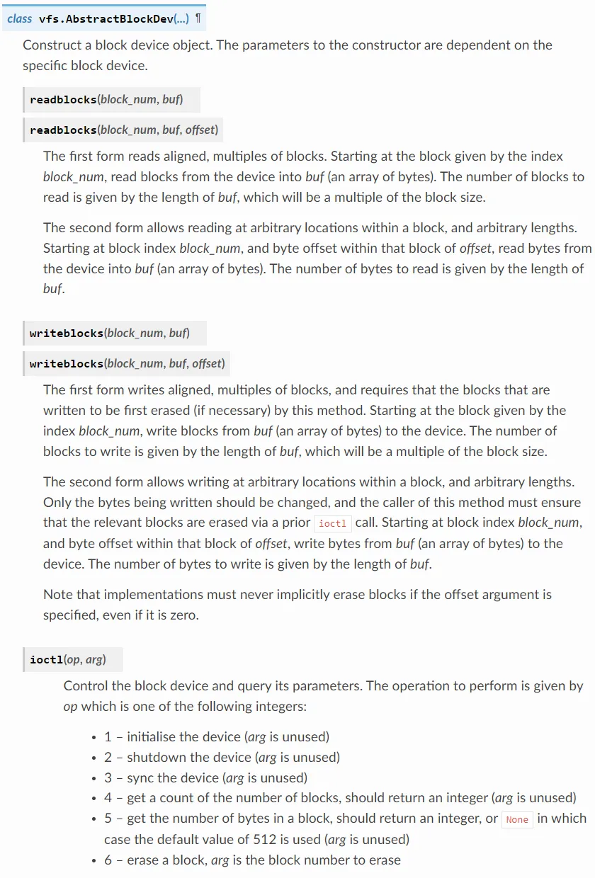
When reading block device data via the readblocks method and writing block device data via the writeblocks method, the offset offset is set as a default parameter to support non-block-aligned reads and writes of arbitrary-length data; additionally, for the device control operation ioctl method, standard operation code constants are defined in the class attributes:
# Standard opcode constants (class attributes)
IOCTL_INIT = 1      # Device initialization
IOCTL_SHUTDOWN = 2  # Device shutdown
IOCTL_SYNC = 3      # Data synchronization
IOCTL_BLK_COUNT = 4 # Get block count (must be implemented)
IOCTL_BLK_SIZE = 5  # Get block size (optional)
IOCTL_BLK_ERASE = 6 # Block erase (required by littlefs)
3.3.2 Implementation of RAM Block Device Class
Specific block device classes (such as RAM block devices, SD cards, etc.) need to inherit from the abstract base class vfs.AbstractBlockDev and implement the methods defined within it. We have implemented a simple RAM block device RAMBlockDev, and the RAMBlockDev class is placed in a separate. py file:
# Python env   : MicroPython v1.23.0
# -*- coding: utf-8 -*-
# @Time    : 2024/9/18 PM 12:15
# @Author  : Li Qingshui
# @File    : ram_block_dev.py.py
# @Description : Inherits the AbstractBlockDev class and implements a simple RAM block device RAMBlockDev, including block read/write operations and device control functions

# ======================================== Import Modules =========================================

# Import the abstract base class of the virtual file block device
from AbstractBlockDevInterface import AbstractBlockDev

# ======================================== Global Variables ============================================

# Define error code constants, conforming to POSIX standard error codes
ENOERR = 0       # Operation successful
EPERM = 1        # Operation not permitted
EIO = 5          # I/O error
ENODEV = 19      # Invalid device/block number
EROFS = 30       # Read-only file system
EINVAL = 22      # Invalid argument

# ======================================== Functions ============================================

# ======================================== Custom Classes ============================================

class RAMBlockDev(AbstractBlockDev):
    """
    RAM-simulated block device implementation, using an in-memory byte array as the storage medium

    Attributes:
        block_size (int): Size of each block in bytes (read-only)
        num_blocks (int): Total number of blocks on the device (read-only)
        initialized (bool): Device initialization state flag
    """

    def __init__(self, block_size: int, num_blocks: int) -> None:
        """
        Initialize the RAM block device

        Args:
            block_size (int): Size of each block in bytes (must be ≥512)
            num_blocks (int): Total number of blocks (must be ≥1)

        Raises:
            ValueError: Raised when block_size<512 or num_blocks<1
        """
        # Check parameters
        if block_size < 512:
            raise ValueError("Block size must be ≥512 bytes")
        if num_blocks < 1:
            raise ValueError("At least 1 block required")

        # Block size
        self.block_size = block_size
        # Number of blocks
        self.num_blocks = num_blocks
        # Create a byte array as the device storage
        self.data = bytearray(block_size * num_blocks)
        # Device initialization state flag
        self.initialized = False

    def readblocks(self, block_num: int, buf: bytearray, offset: int = 0) -> None:
        """
        Read data from the device (supports extended interface)

        Args:
            block_num (int): Starting block number (0 ≤ block_num < num_blocks)
            buf (bytearray): Buffer that receives the data
            offset (int): Byte offset within the block (default 0)

        Returns:
            None

        Raises:
            OSError: If block_num is out of range (uses ENODEV).
            OSError: If the read exceeds the current block range (uses EIO).
        """
        # Check whether block_num is within the valid range
        if not 0 <= block_num < self.num_blocks:
            raise OSError(ENODEV)

        # Calculate the start position of the read
        start = block_num * self.block_size + offset
        # Calculate the end position of the read
        end = start + len(buf)

        # Make sure the data read does not exceed the block range
        if end > (block_num + 1) * self.block_size:
            raise OSError(EIO)

        # Read data from the device storage into the buffer
        buf[:] = self.data[start:end]

    def writeblocks(self, block_num: int, buf: bytearray | None, offset: int = 0) -> None:
        """
        Write data to the device (supports erase operation)

        Args:
            block_num (int): Target block number (0 ≤ block_num < num_blocks)
            buf (bytearray|None):
                - bytearray: Data to write
                - None: Erase the specified block (offset must be 0)
            offset (int): Byte offset within the block (default 0)

        Returns:
            None

        Raises:
            OSError: If block_num is out of range (uses ENODEV).
            OSError: If the write exceeds the current block range (uses EIO).
            OSError: If offset ≠ 0 during an erase operation (uses OSError(22) for invalid argument).
        """
        # Check whether block_num is within the valid range
        if not 0 <= block_num < self.num_blocks:
            raise OSError(ENODEV)

        # Perform block erase operation
        if buf is None:
            if offset != 0:
                # Invalid argument, erase must be done on a whole block
                raise OSError(EINVAL)
            # Erase the specified block
            start = block_num * self.block_size
            end = (block_num + 1) * self.block_size
            self.data[start:end] = bytes(self.block_size)
            return

        # Calculate the start position of the write
        start = block_num * self.block_size
        # Calculate the end position of the write
        end = start + len(buf)

        # Make sure the data written does not exceed the block range
        if end > (block_num + 1) * self.block_size:
            raise OSError(EIO)

        # Write data to the device storage
        self.data[start:end] = buf

    def ioctl(self, op: int, arg: int | None = None) -> int | None:
        """
        Device control operation.

        Args:
            op (int): Opcode (class constants should be used):
                - AbstractBlockDev.IOCTL_INIT (1)       : Initialize the device.
                - AbstractBlockDev.IOCTL_SHUTDOWN (2)   : Shut down the device.
                - AbstractBlockDev.IOCTL_SYNC (3)       : Synchronize data.
                - AbstractBlockDev.IOCTL_BLK_COUNT (4)  : Get the total number of blocks on the device (must be implemented).
                - AbstractBlockDev.IOCTL_BLK_SIZE (5)   : Get the block size (optional).
                - AbstractBlockDev.IOCTL_BLK_ERASE (6)  : Erase a block (required by littlefs).
            arg (int | None, optional): Operation argument, depends on op:
                - For IOCTL_BLK_ERASE (6): pass the block number to erase (int).
                - For other operations: can be None or 0, as defined by the subclass.

        Returns:
            int | None:
                - For IOCTL_BLK_COUNT (4): returns the total number of blocks on the device (int).
                - For IOCTL_BLK_SIZE (5) : returns the block size (int).
                - For IOCTL_BLK_ERASE (6): returns 0 if the erase succeeds.
                - For other operations: returns 0 or None by default.

        Raises:
            OSError: If the block number is out of range during erase (uses ENODEV).
            OSError: If op is not supported (uses EPERM).
        """
        # Handle different operations
        # Initialize the device
        if op == AbstractBlockDev.IOCTL_INIT:
            self.initialized = True
            # Return 0 to indicate initialization succeeded
            return 0
        # Shut down the device
        elif op == AbstractBlockDev.IOCTL_SHUTDOWN:
            self.initialized = False
            return 0
        # Synchronize the device
        elif op == AbstractBlockDev.IOCTL_SYNC:
            # In a RAM block device, writes take effect immediately, so no extra synchronization is needed
            # Return 0 to indicate synchronization succeeded
            return 0
        # Get the number of blocks
        elif op == AbstractBlockDev.IOCTL_BLK_COUNT:
            # Return the total number of blocks
            return self.num_blocks
        # Get the block size
        elif op == AbstractBlockDev.IOCTL_BLK_SIZE:
            # Return the block size
            return self.block_size
        # Erase a block
        elif op == AbstractBlockDev.IOCTL_BLK_ERASE:
            # Check whether the argument was passed correctly
            if arg is None:
                raise OSError(ENODEV)
            # Get the block number to erase
            block_num = arg
            if 0 <= block_num < self.num_blocks:
                # Calculate the start position of the erase
                start = block_num * self.block_size
                # Calculate the end position of the erase
                end = (block_num+1)*self.block_size
                # Set the data of the specified block to all 0 (erase)
                self.data[start:end] = bytes(self.block_size)
                # Return 0 to indicate erase succeeded
                return 0
            else:
                # Block number out of range
                raise OSError(ENODEV)
        # Handle unsupported operation codes
        else:
            # Raise an exception
            raise OSError(EPERM)

# ======================================== Initialization ==========================================

# ========================================  Main Program  ===========================================
RAMBlockDev class emulates a RAM-based block device, which uses an in-memory bytearray to store data:
- In the initialization method, use
bytearrayto create a memory buffer to simulate the storage area of a block device - Provides
readblocks (),writeblocks ()andioctl ()interfaces to ensure compatibility with MicroPython's VFS (Virtual File System). - In control and query operations, it receives the corresponding operation codes and parameters to execute the corresponding commands, and supports operations such as device initialization, synchronization, and erasure.
In the initialization method, organize multiple blocks into a contiguous byte array:
self.data = bytearray(block_size * num_blocks)Then a block addressing formula can be derived, namely start address of block N = N * block_size.
In the read operation (readblocks), the following operations are performed in sequence:
- Calculate the starting position for reading:
start = block_num * self.block_size + offset. - Calculate the end position for reading:
end = start + len (buf). - Boundary Check:
block_numis out of range (throwsOSError (ENODEV)).endmust not exceed the block size ofblock_num; otherwise,OSError (EIO)will be thrown.
- Data Copy:
buf[:] = self.data[start: end]: Assigns a slice of abytearraytobufto avoid extra memory allocation by Python.
In a write operation (writeblocks), the process is similar to that of a read operation (readblocks): first, boundary checking is performed, then the start and end ranges of the write address are calculated. During writing, the bytearray is directly modified to avoid creating additional objects. Additionally, when buf= None, an erase operation is executed (filling the entire block with 0x00).
In the control command ioctl (), corresponding operations are performed according to the input device management instruction and entry parameters: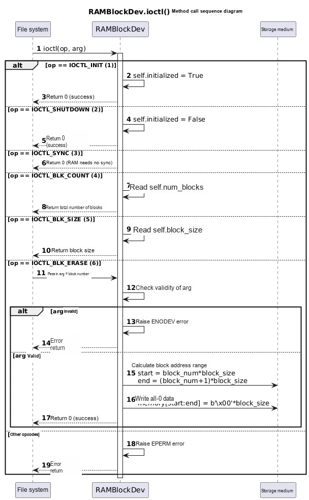
IOCTL_INIT(1): Initialize the device and setself.initialized = True.IOCTL_SHUTDOWN(2): Device shutdown, setself.initialized = False.IOCTL_SYNC(3): No synchronization is required in RAM, and 0 is returned directly0.IOCTL_BLK_COUNT(4): Returnsnum_blocksfor the file system to query.IOCTL_BLK_SIZE(5): Returnsblock_size.IOCTL_BLK_ERASE(6): Erases a single block (sets it to all0x00).- Other operations return
OSError (EPERM), indicating that the operation is not permitted.
In addition, we have defined error codes (errno) compliant with the POSIX standard (Portable Operating System Interface) to indicate the reasons for the failure of system calls or library function execution:
ENOERR = 0(No error)—— The operation succeeded.EPERM = 1(Operation not permitted)—— Insufficient permission to perform the operation, for example, an ordinary user attempting to modify system files.EIO = 5(I/O error)—— Input/output error, e. g. disk read/write failure.ENODEV = 19(No such device)—— The device does not exist, which usually occurs when attempting to access an unconnected external device.EROFS = 30(Read-only File System)—— An attempt was made to perform a write operation on a read-only file system.EINVAL = 22(Invalid argument)—— The parameter passed is invalid, such as a division-by-zero operation or out-of-bounds access.
We can learn more about it via the following link:
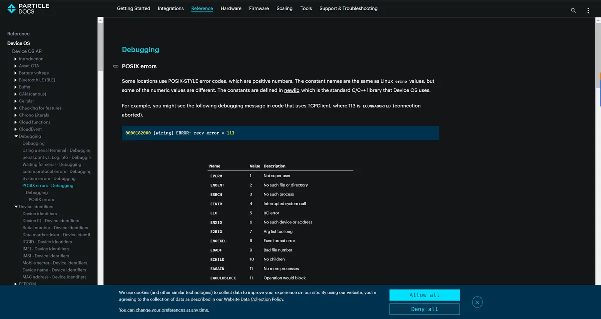
https://docs.particle.io/reference/device-os/api/debugging/posix-errors/
3.3.3 Application Experiment
The following code can be found in the elegance-devkit v1\Demo\72 FileSys_BlockDev folder in the resource package we provide.
This block device can be used to create and mount a file system, as well as to create, read from and write to files. In the following code, we test the RAM-based block device RAMBlockDev class, including the verification of write, read and control operations. The sample code is as follows:
# Python env   : MicroPython v1.23.0
# -*- coding: utf-8 -*-
# @Time    : 2024/9/18 PM 12:15
# @Author  : Li Qingshui
# @File    : main.py
# @Description : Test the functionality of the RAMBlockDev class, including verification of write, read, and control operations

# ======================================== Import Modules =========================================

# Import the custom block device implementation class
from ram_block_dev import RAMBlockDev
# Import the virtual file class
import vfs
# Import time-related modules
import time

# ======================================== Global Variables ============================================

# ======================================== Functions ============================================

# ======================================== Custom Classes ============================================

# ======================================== Initialization ==========================================

# Power-on delay of 3 s
time.sleep(3)
# Print debug information
print("FreakStudio : RAMBlockDev Write and Read Test")

# Create a RAM block device with a block size of 512 bytes and 50 blocks in total
bdev = RAMBlockDev(512, 50)
# Create a FAT file system on the block device
vfs.VfsFat.mkfs(bdev)
# Mount the block device to the /ramdisk directory of the virtual file system
vfs.mount(bdev, '/ramdisk')

# ========================================  Main Program  ===========================================

# In the created virtual file system, create a file hello.txt and open it
with open('/ramdisk/hello.txt', 'w') as f:
    # Write content
    f.write('FreakStudio : Hello World')

# Read the file content and print it
print(open('/ramdisk/hello.txt').read())
In this code, we first create a RAM block device with a block size of 512 bytes and a total of 50 blocks, create a FAT file system on the block device, and mount the block device to the /ramdisk directory so that it can be used as a file system; then in the mounted virtual file system /ramdisk, we create and open a file named hello.txt, write data into it and then read the data back.
Burn the code, open the terminal, and the following content will be displayed:
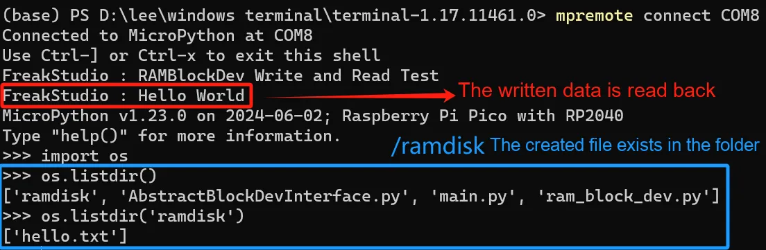
It can be seen that the file system and files have been created successfully, and the data written to the file has been read successfully.
We can try to read the block data of the RAM block device bdev. First, create a bytearray buffer with a size of 512 bytes:
buf = bytearray(512)Then use the bdev readblocks method to read block data. First, read the 0th block of data, which is the boot sector data:
>>> bdev.readblocks(0, buf, 0)
>>> buf
bytearray(b'\xeb\xfe\x90MSDOS5.0\x00\x02\x01\x01\x00\x01\x00\x022\x00\xf8\x01\x00?\x00\xff\x00\x00\x00\x00\x00\x00\x00\x00\x00\x80\x00).\x00!RNO NAME    FAT     \x00\x00\x00\x00\x00\x00\x00\x00\x00\x00\x00\x00\x00\x00\x00\x00\x00\x00\x00\x00\x00\x00\x00\x00\x00\x00\x00\x00\x00\x00\x00\x00\x00\x00\x00\x00\x00\x00\x00\x00\x00\x00\x00\x00\x00\x00\x00\x00\x00\x00\x00\x00\x00\x00\x00\x00\x00\x00\x00\x00\x00\x00\x00\x00\x00\x00\x00\x00\x00\x00\x00\x00\x00\x00\x00\x00\x00\x00\x00\x00\x00\x00\x00\x00\x00\x00\x00\x00\x00\x00\x00\x00\x00\x00\x00\x00\x00\x00\x00\x00\x00\x00\x00\x00\x00\x00\x00\x00\x00\x00\x00\x00\x00\x00\x00\x00\x00\x00\x00\x00\x00\x00\x00\x00\x00\x00\x00\x00\x00\x00\x00\x00\x00\x00\x00\x00\x00\x00\x00\x00\x00\x00\x00\x00\x00\x00\x00\x00\x00\x00\x00\x00\x00\x00\x00\x00\x00\x00\x00\x00\x00\x00\x00\x00\x00\x00\x00\x00\x00\x00\x00\x00\x00\x00\x00\x00\x00\x00\x00\x00\x00\x00\x00\x00\x00\x00\x00\x00\x00\x00\x00\x00\x00\x00\x00\x00\x00\x00\x00\x00\x00\x00\x00\x00\x00\x00\x00\x00\x00\x00\x00\x00\x00\x00\x00\x00\x00\x00\x00\x00\x00\x00\x00\x00\x00\x00\x00\x00\x00\x00\x00\x00\x00\x00\x00\x00\x00\x00\x00\x00\x00\x00\x00\x00\x00\x00\x00\x00\x00\x00\x00\x00\x00\x00\x00\x00\x00\x00\x00\x00\x00\x00\x00\x00\x00\x00\x00\x00\x00\x00\x00\x00\x00\x00\x00\x00\x00\x00\x00\x00\x00\x00\x00\x00\x00\x00\x00\x00\x00\x00\x00\x00\x00\x00\x00\x00\x00\x00\x00\x00\x00\x00\x00\x00\x00\x00\x00\x00\x00\x00\x00\x00\x00\x00\x00\x00\x00\x00\x00\x00\x00\x00\x00\x00\x00\x00\x00\x00\x00\x00\x00\x00\x00\x00\x00\x00\x00\x00\x00\x00\x00\x00\x00\x00\x00\x00\x00\x00\x00\x00\x00\x00\x00\x00\x00\x00\x00\x00\x00\x00\x00\x00\x00\x00\x00\x00\x00\x00\x00\x00\x00\x00\x00\x00\x00\x00\x00\x00\x00\x00\x00\x00\x00\x00\x00\x00\x00\x00\x00\x00\x00\x00\x00\x00\x00\x00\x00\x00\x00\x00\x00\x00\x00\x00\x00\x00\x00\x00\x00\x00\x00\x00\x00\x00\x00\x00\x00\x00\x00\x00\x00\x00\x00\x00\x00\x00\x00\x00\x00\x00\x00\x00\x00\x00\x00\x00\x00\x00\x00\x00\x00\x00\x00\x00\x00\x00\x00\x00U\xaa')
The output data includes the boot sector signature, OEM identifier, key BPB parameters, etc. :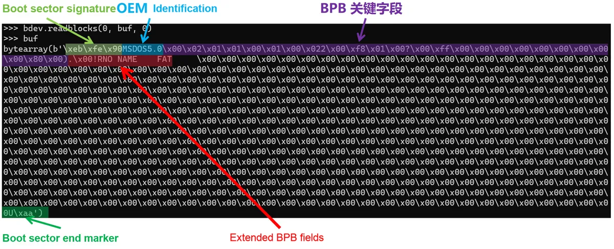
- Boot sector signature: the content is
bytearray (b'\xeb\xfe\x90MSDOS5.0'). The boot sector of the FAT file system starts with\xEB, which is a short jump instruction (JMP) used to skip part of the boot code, and\x90is a padding byte. - OEM Identifier:
MSDOS5.0indicates that this is a FAT file system compatible with MSDOS 5.0. - Key Fields of BPB: The descriptions are as follows:
\x00\x02   # Bytes per sector (usually 512, i.e. 0x0200)
\x01       # Sectors per cluster (1 sector)
\x01\x00   # Number of reserved sectors (usually 1)
\x01       # Number of FAT tables (usually 2)
\x00\x02   # Number of root directory entries (32 root directory entries)
2\x00\xf8  # Media descriptor (0xF8 means hard disk)
It also includes information such as the number of hidden sectors and the number of sectors per FAT table.
- Extended BPB fields:
NO NAMEindicates an unnamed volume, andFAT12indicates the formatting type. - Boot sector end signature:
0x55 0xAAis the end signature of a boot sector.
Then read the first block of data, which is the FAT table data:
>>> bdev.readblocks(1, buf, 0)
>>> buf
bytearray(b'\xf8\xff\xff\xff\x0f\x00\x00\x00\x00\x00\x00\x00\x00\x00\x00\x00\x00\x00\x00\x00\x00\x00\x00\x00\x00\x00\x00\x00\x00\x00\x00\x00\x00\x00\x00\x00\x00\x00\x00\x00\x00\x00\x00\x00\x00\x00\x00\x00\x00\x00\x00\x00\x00\x00\x00\x00\x00\x00\x00\x00\x00\x00\x00\x00\x00\x00\x00\x00\x00\x00\x00\x00\x00\x00\x00\x00\x00\x00\x00\x00\x00\x00\x00\x00\x00\x00\x00\x00\x00\x00\x00\x00\x00\x00\x00\x00\x00\x00\x00\x00\x00\x00\x00\x00\x00\x00\x00\x00\x00\x00\x00\x00\x00\x00\x00\x00\x00\x00\x00\x00\x00\x00\x00\x00\x00\x00\x00\x00\x00\x00\x00\x00\x00\x00\x00\x00\x00\x00\x00\x00\x00\x00\x00\x00\x00\x00\x00\x00\x00\x00\x00\x00\x00\x00\x00\x00\x00\x00\x00\x00\x00\x00\x00\x00\x00\x00\x00\x00\x00\x00\x00\x00\x00\x00\x00\x00\x00\x00\x00\x00\x00\x00\x00\x00\x00\x00\x00\x00\x00\x00\x00\x00\x00\x00\x00\x00\x00\x00\x00\x00\x00\x00\x00\x00\x00\x00\x00\x00\x00\x00\x00\x00\x00\x00\x00\x00\x00\x00\x00\x00\x00\x00\x00\x00\x00\x00\x00\x00\x00\x00\x00\x00\x00\x00\x00\x00\x00\x00\x00\x00\x00\x00\x00\x00\x00\x00\x00\x00\x00\x00\x00\x00\x00\x00\x00\x00\x00\x00\x00\x00\x00\x00\x00\x00\x00\x00\x00\x00\x00\x00\x00\x00\x00\x00\x00\x00\x00\x00\x00\x00\x00\x00\x00\x00\x00\x00\x00\x00\x00\x00\x00\x00\x00\x00\x00\x00\x00\x00\x00\x00\x00\x00\x00\x00\x00\x00\x00\x00\x00\x00\x00\x00\x00\x00\x00\x00\x00\x00\x00\x00\x00\x00\x00\x00\x00\x00\x00\x00\x00\x00\x00\x00\x00\x00\x00\x00\x00\x00\x00\x00\x00\x00\x00\x00\x00\x00\x00\x00\x00\x00\x00\x00\x00\x00\x00\x00\x00\x00\x00\x00\x00\x00\x00\x00\x00\x00\x00\x00\x00\x00\x00\x00\x00\x00\x00\x00\x00\x00\x00\x00\x00\x00\x00\x00\x00\x00\x00\x00\x00\x00\x00\x00\x00\x00\x00\x00\x00\x00\x00\x00\x00\x00\x00\x00\x00\x00\x00\x00\x00\x00\x00\x00\x00\x00\x00\x00\x00\x00\x00\x00\x00\x00\x00\x00\x00\x00\x00\x00\x00\x00\x00\x00\x00\x00\x00\x00\x00\x00\x00\x00\x00\x00\x00\x00\x00\x00\x00\x00\x00\x00\x00\x00\x00\x00\x00\x00\x00\x00\x00\x00\x00\x00\x00\x00\x00\x00\x00\x00\x00\x00\x00\x00\x00\x00\x00\x00\x00\x00\x00\x00\x00\x00\x00\x00\x00\x00\x00\x00\x00\x00\x00\x00\x00\x00\x00\x00\x00\x00\x00\x00\x00\x00\x00\x00\x00\x00\x00\x00\x00\x00\x00\x00')
The output data content includes the information of reserved clusters and file cluster chains: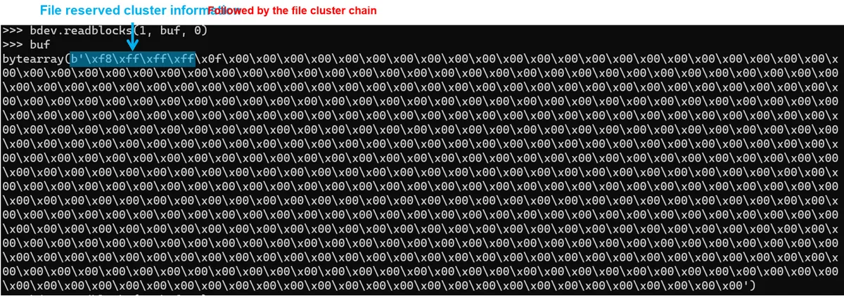
- Reserved Cluster:
\xf8\xff\xff\xffis the reserved cluster of FAT (0xFFF8), indicating that this sector is the FAT media descriptor. - File cluster chain information: the subsequent
\x0f\x00\x00\x00.. .is the FAT entry, which indicates allocated and free clusters; here cluster 2 is0x000F, meaning the filehello.txtexclusively occupies cluster 2.
Then we read the second block of data, which here corresponds to the FAT directory area:
>>> bdev.readblocks(2, buf, 0)
>>> buf
bytearray(b'HELLO   TXT \x18\x00.\x00!R\x00\x00\x00\x00.\x00!R\x02\x00\x19\x00\x00\x00\x00\x00\x00\x00\x00\x00\x00\x00\x00\x00\x00\x00\x00\x00\x00\x00\x00\x00\x00\x00\x00\x00\x00\x00\x00\x00\x00\x00\x00\x00\x00\x00\x00\x00\x00\x00\x00\x00\x00\x00\x00\x00\x00\x00\x00\x00\x00\x00\x00\x00\x00\x00\x00\x00\x00\x00\x00\x00\x00\x00\x00\x00\x00\x00\x00\x00\x00\x00\x00\x00\x00\x00\x00\x00\x00\x00\x00\x00\x00\x00\x00\x00\x00\x00\x00\x00\x00\x00\x00\x00\x00\x00\x00\x00\x00\x00\x00\x00\x00\x00\x00\x00\x00\x00\x00\x00\x00\x00\x00\x00\x00\x00\x00\x00\x00\x00\x00\x00\x00\x00\x00\x00\x00\x00\x00\x00\x00\x00\x00\x00\x00\x00\x00\x00\x00\x00\x00\x00\x00\x00\x00\x00\x00\x00\x00\x00\x00\x00\x00\x00\x00\x00\x00\x00\x00\x00\x00\x00\x00\x00\x00\x00\x00\x00\x00\x00\x00\x00\x00\x00\x00\x00\x00\x00\x00\x00\x00\x00\x00\x00\x00\x00\x00\x00\x00\x00\x00\x00\x00\x00\x00\x00\x00\x00\x00\x00\x00\x00\x00\x00\x00\x00\x00\x00\x00\x00\x00\x00\x00\x00\x00\x00\x00\x00\x00\x00\x00\x00\x00\x00\x00\x00\x00\x00\x00\x00\x00\x00\x00\x00\x00\x00\x00\x00\x00\x00\x00\x00\x00\x00\x00\x00\x00\x00\x00\x00\x00\x00\x00\x00\x00\x00\x00\x00\x00\x00\x00\x00\x00\x00\x00\x00\x00\x00\x00\x00\x00\x00\x00\x00\x00\x00\x00\x00\x00\x00\x00\x00\x00\x00\x00\x00\x00\x00\x00\x00\x00\x00\x00\x00\x00\x00\x00\x00\x00\x00\x00\x00\x00\x00\x00\x00\x00\x00\x00\x00\x00\x00\x00\x00\x00\x00\x00\x00\x00\x00\x00\x00\x00\x00\x00\x00\x00\x00\x00\x00\x00\x00\x00\x00\x00\x00\x00\x00\x00\x00\x00\x00\x00\x00\x00\x00\x00\x00\x00\x00\x00\x00\x00\x00\x00\x00\x00\x00\x00\x00\x00\x00\x00\x00\x00\x00\x00\x00\x00\x00\x00\x00\x00\x00\x00\x00\x00\x00\x00\x00\x00\x00\x00\x00\x00\x00\x00\x00\x00\x00\x00\x00\x00\x00\x00\x00\x00\x00\x00\x00\x00\x00\x00\x00\x00\x00\x00\x00\x00\x00\x00\x00\x00\x00\x00\x00\x00\x00\x00\x00\x00\x00\x00\x00\x00\x00\x00\x00\x00\x00\x00\x00\x00\x00\x00\x00\x00\x00\x00\x00\x00\x00\x00\x00\x00\x00\x00\x00\x00\x00\x00\x00\x00\x00\x00\x00\x00\x00\x00\x00\x00\x00\x00\x00\x00\x00\x00\x00\x00\x00\x00\x00\x00\x00\x00\x00\x00\x00\x00\x00\x00\x00\x00\x00')
The output data includes the directory information of the files that have been stored so far: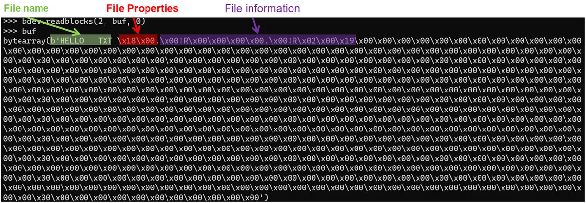
- File name:
HELLO TXTdenotes a file name that conforms to the 8.3 file name format of FAT16/FAT32, whereHELLOis the 8-byte file name andTXTis the 3-byte extension. - File Attributes:
0x18and0x00are the file attribute bit and reserved bit respectively. - File Information:
.\x00! R\x00\x00\x00\x00.\x00! R\x02\x00indicates information such as file creation time, starting cluster number, size, etc.
We can try to find the data blocks storing the content of the hello.txt file with the following code:
search_str = b'FreakStudio : Hello World'

for block_num in range(50):  # Scan all 50 blocks
    buf = bytearray(512)
    bdev.readblocks(block_num, buf, 0)
    if search_str in buf:
        print(f"Found file content in block: {block_num}")
        break
The output result is 34. Let's check the content in the 34th block:
Found file content in block: 34
>>> bdev.readblocks(34, buf, 0)
>>> buf
bytearray(b'FreakStudio : Hello World\x00\x00\x00\x00\x00\x00\x00\x00\x00\x00\x00\x00\x00\x00\x00\x00\x00\x00\x00\x00\x00\x00\x00\x00\x00\x00\x00\x00\x00\x00\x00\x00\x00\x00\x00\x00\x00\x00\x00\x00\x00\x00\x00\x00\x00\x00\x00\x00\x00\x00\x00\x00\x00\x00\x00\x00\x00\x00\x00\x00\x00\x00\x00\x00\x00\x00\x00\x00\x00\x00\x00\x00\x00\x00\x00\x00\x00\x00\x00\x00\x00\x00\x00\x00\x00\x00\x00\x00\x00\x00\x00\x00\x00\x00\x00\x00\x00\x00\x00\x00\x00\x00\x00\x00\x00\x00\x00\x00\x00\x00\x00\x00\x00\x00\x00\x00\x00\x00\x00\x00\x00\x00\x00\x00\x00\x00\x00\x00\x00\x00\x00\x00\x00\x00\x00\x00\x00\x00\x00\x00\x00\x00\x00\x00\x00\x00\x00\x00\x00\x00\x00\x00\x00\x00\x00\x00\x00\x00\x00\x00\x00\x00\x00\x00\x00\x00\x00\x00\x00\x00\x00\x00\x00\x00\x00\x00\x00\x00\x00\x00\x00\x00\x00\x00\x00\x00\x00\x00\x00\x00\x00\x00\x00\x00\x00\x00\x00\x00\x00\x00\x00\x00\x00\x00\x00\x00\x00\x00\x00\x00\x00\x00\x00\x00\x00\x00\x00\x00\x00\x00\x00\x00\x00\x00\x00\x00\x00\x00\x00\x00\x00\x00\x00\x00\x00\x00\x00\x00\x00\x00\x00\x00\x00\x00\x00\x00\x00\x00\x00\x00\x00\x00\x00\x00\x00\x00\x00\x00\x00\x00\x00\x00\x00\x00\x00\x00\x00\x00\x00\x00\x00\x00\x00\x00\x00\x00\x00\x00\x00\x00\x00\x00\x00\x00\x00\x00\x00\x00\x00\x00\x00\x00\x00\x00\x00\x00\x00\x00\x00\x00\x00\x00\x00\x00\x00\x00\x00\x00\x00\x00\x00\x00\x00\x00\x00\x00\x00\x00\x00\x00\x00\x00\x00\x00\x00\x00\x00\x00\x00\x00\x00\x00\x00\x00\x00\x00\x00\x00\x00\x00\x00\x00\x00\x00\x00\x00\x00\x00\x00\x00\x00\x00\x00\x00\x00\x00\x00\x00\x00\x00\x00\x00\x00\x00\x00\x00\x00\x00\x00\x00\x00\x00\x00\x00\x00\x00\x00\x00\x00\x00\x00\x00\x00\x00\x00\x00\x00\x00\x00\x00\x00\x00\x00\x00\x00\x00\x00\x00\x00\x00\x00\x00\x00\x00\x00\x00\x00\x00\x00\x00\x00\x00\x00\x00\x00\x00\x00\x00\x00\x00\x00\x00\x00\x00\x00\x00\x00\x00\x00\x00\x00\x00\x00\x00\x00\x00\x00\x00\x00\x00\x00\x00\x00\x00\x00\x00\x00\x00\x00\x00\x00\x00\x00\x00\x00\x00\x00\x00\x00\x00\x00\x00\x00\x00\x00\x00\x00\x00\x00\x00\x00\x00\x00\x00\x00\x00\x00\x00\x00\x00\x00\x00\x00\x00\x00\x00\x00')
It can be seen that the verification is correct, hello.txt and the content of the file is stored in the 34th data block.
Actually, when formatting a file system, the main process can be summarized as follows: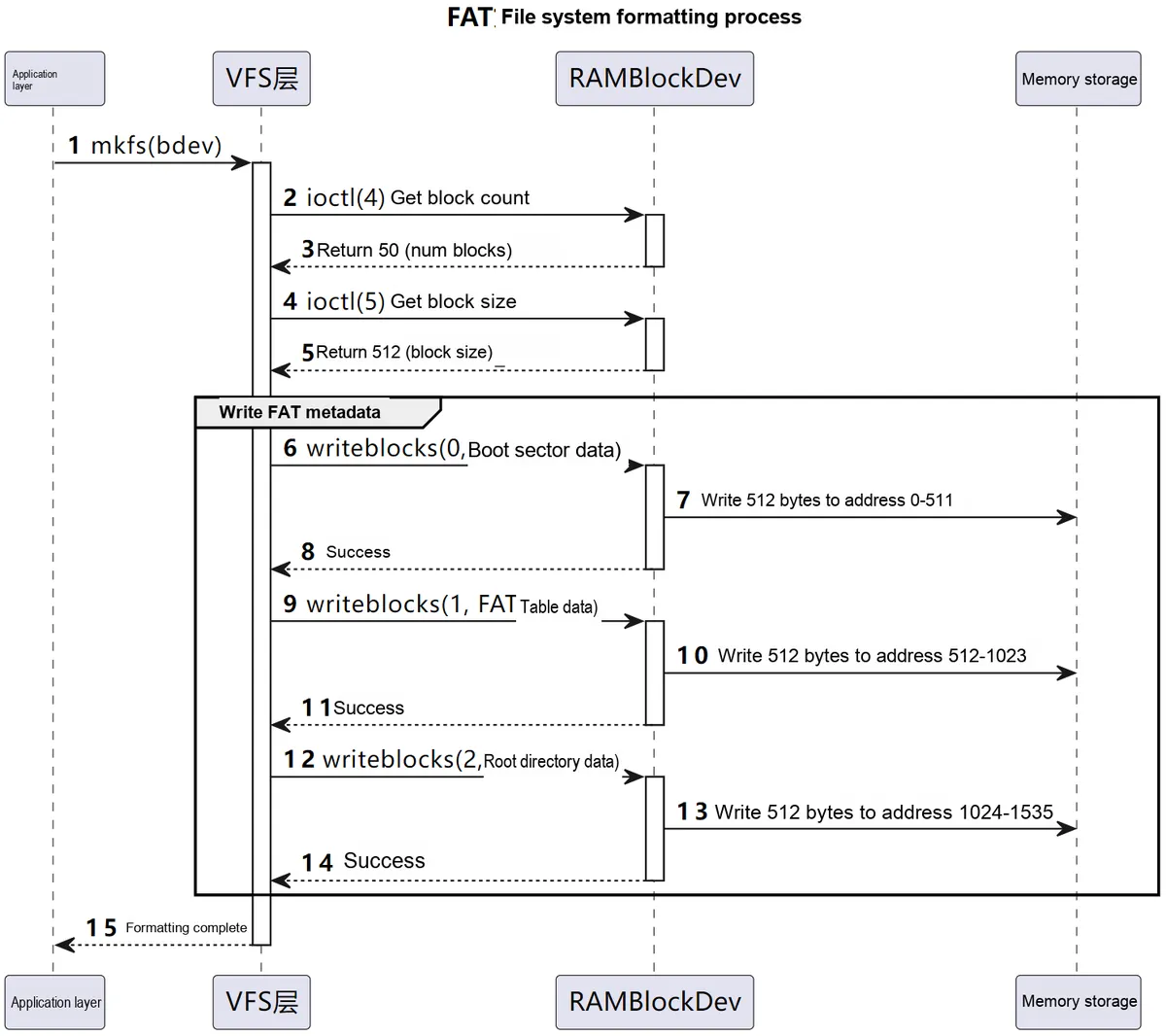
- Call
bdev.ioctl (4)to obtain the number of blocks; - Call
bdev.ioctl (5)to get the block size; - Write FAT file system metadata to the storage medium, including the boot sector, FAT table, root directory area, etc.
When writing to a file, perform the following operations: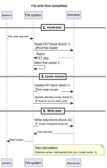
- The file system searches for free clusters (by calling
bdev.readblocks ()to read the FAT table); - Allocate cluster chains and update the FAT table (call
bdev.writeblocks ()); - Write the content to the file.
When reading a file, perform the following operations: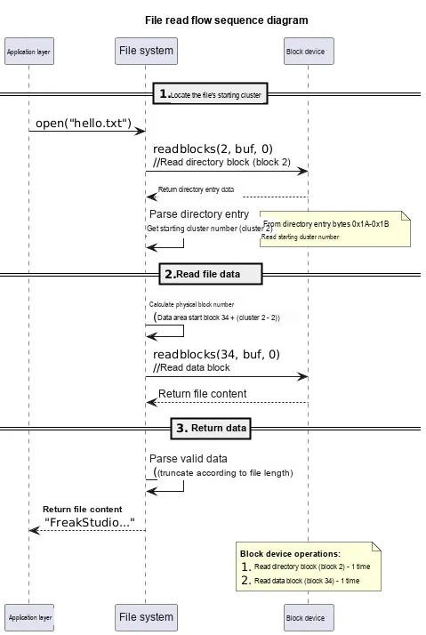
- Locate the starting cluster of the file via the directory entry.
- Call
bdev.readblocks ()to read file data. - Returns the content to the application layer.
3.4 SD Card Mounting File System
3.4.1 Basic Knowledge of SD Card
Anatomy of SD Card Communication Protocol: Structure of CMD Commands and Their Response Messages
3.4.1.1 Introduction and Classification of SD Cards
An SD card is a removable storage device widely used in digital devices, featuring small size, low power consumption and large capacity. It is mainly used to store information such as data, music, videos and images, and is widely applied in mobile phones, cameras, tablets, embedded devices and other products.
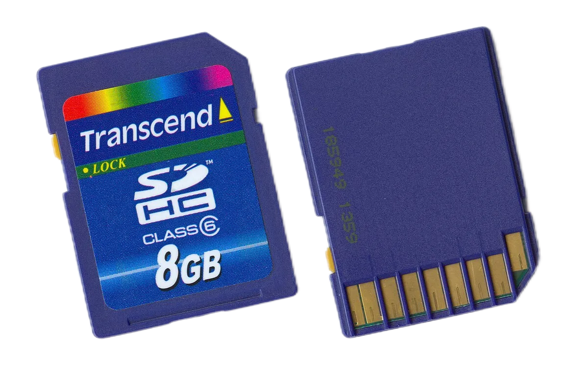
Based on their physical dimensions, SD cards can be categorized into the following types: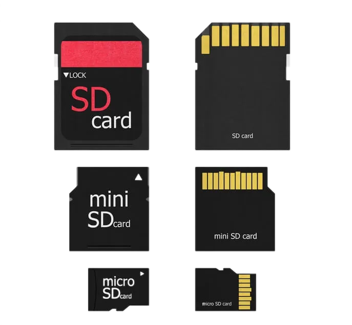
- Standard SD card: dimensions are 32mm x 24mm x 2.1mm, used for large devices such as cameras, recording equipment, etc.
- miniSD card: measures 21.5mm x 20mm x 1.4mm, is relatively uncommon, and is mainly used in early mobile phones
- microSD card: also known as TF card, measures 15mm x 11mm x 1mm, is widely used in small devices such as mobile phones, drones and Raspberry Pi, and can be converted into an SD card via an SD card adapter
Depending on their storage capacity and supported protocols, SD cards can be categorized into the following types:
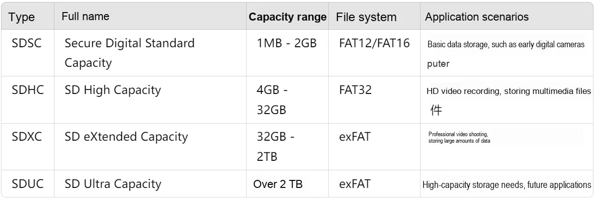
It should be noted here that different file systems support different maximum capacity limits and applicable devices:
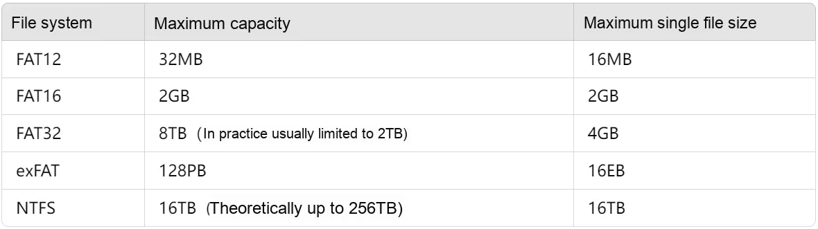
Here, let’s supplement two basic concepts:
- Maximum capacity: refers to the upper limit of the total space of storage devices that this file system can "manage"(for example, FAT12 can manage devices up to 32MB at maximum);
- Maximum size of a single file: refers to the maximum storage capacity allowed for one file (for example, files in the FAT32 system cannot exceed 4GB, which may be insufficient for storing large movies);
Wherein:
- FAT12 and FAT16: Mainly used for small-capacity storage devices and suitable for early applications
- FAT32: Widely used in SDHC cards and some larger storage devices, but with a file size limit of 4GB
- exFAT : Designed for flash drives and high-capacity storage devices, it supports larger file sizes and storage capacities, and is suitable for SDXC cards
- NTFS: Primarily used for Windows operating systems, it supports large files and high-capacity storage, but is not commonly applied to SD cards.
The "Speed Class" of an SD card guarantees its minimum write speed (a sufficiently fast speed prevents it from being laggy). Corresponding to different usage scenarios, there are mainly the following common speed classes:
- Class 2: Minimum write speed: 2MB/s, suitable for standard-definition video recording;
- Class 4: Minimum write speed: 4MB/s, suitable for high-definition (HD) video recording;
- Class 6: Minimum write speed 6MB/s, suitable for Full High Definition (FHD) video recording;
- Class 10: Minimum write speed 10MB/s, suitable for high-definition video and continuous shooting;
- UHS-II: supports higher transmission speeds, with a write speed of up to 30MB/s or higher.
3.4.1.2 Basic Structure and Working Principle of SD Card
The mechanical structure of an SD card consists of a plastic casing, metal pins, a memory chip, and a controller. Its casing is typically made of sturdy plastic material, which can withstand physical impacts and environmental factors:
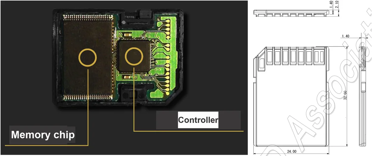
An SD card is like a "USB flash drive with a smart butler", and it functions through the following units:
- Storage Core: Stores data using NAND flash memory (similar to the storage chips in mobile phones);
- Smart Home Manager (Controller):
- Receive commands from external devices (such as "read XX file") and then search for data in the flash memory;
- Manage data with a file system (FAT32/exFAT) — the VFS mentioned earlier can interface with this;
- Wear leveling technology: it stores data in different areas of the flash memory in turn to prevent a certain block from being written frequently and damaged prematurely (just like storing items in different drawers in rotation);
- Built-in error correction: Automatically detects and fixes minor errors in data to prevent content reading mistakes.
The bottom of an SD card features multiple metal pins for data transmission, power supply and signal control; a standard SD card has 9 pins, while a microSD card has 8:
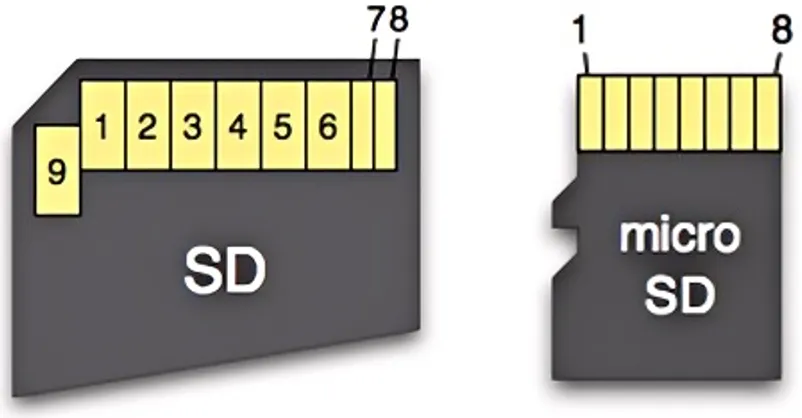
The 9 pins of an SD card can be divided into four data transfer pins DAT0 to DAT3, a command pin CMD, ground pins VSS and power supply pins VDD, and most SD cards also have a write protect (WP) switch in standard SD cards:
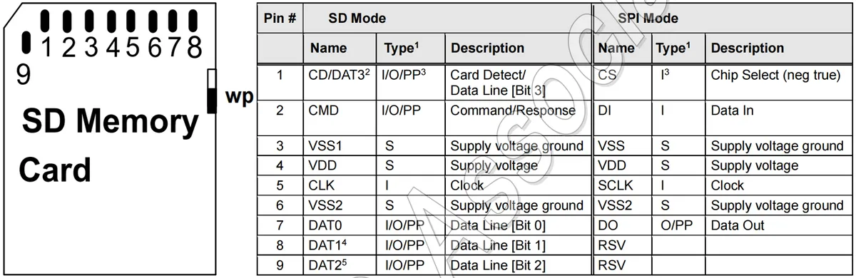
Before introducing the functions of each pin, we need to know that SD cards have two common operation modes:
- SD Mode: High-speed yet with numerous pins and complex communication, it is generally used in professional devices such as mobile phones and cameras;
- SPI Mode: It features fewer pins and simple communication, making it a common mode in embedded programming (e. g., connecting an SD card to a development board); beginners can focus primarily on this mode.
The following are the corresponding functions of each pin in the two modes:
| Pin number | SD Mode (high-speed mode) | SPI Mode (commonly used in embedded systems) |
| 1 | Name: CD/DAT3 Type: I/O/PP Function: card insertion detection + data transfer pin (bit 3) | Name: CS Type: I Function: chip select (the switch with which an external device "selects" the SD card, active low) |
| 2 | Name: CMD Type: I/O/PP Function: send/receive commands and responses (e.g., the "read data" command) | Name: DI Type: I Function: data input (the SD card receives data from the external device) |
| 3 | Name: VSS1 Type: S Function: power ground (connect to the development board's GND) | Name: VSS Type: S Function: power ground (same as left) |
| 4 | Name: VDD Type: S Function: power supply (connect to 3.3V, do not connect to 5V! It will burn out the card) | Name: VDD Type: S Function: power supply (same as left) |
| 5 | Name: CLK Type: I Function: clock signal (the "metronome" for synchronous communication) | Name: SCLK Type: I Function: Clock signal (same as left) |
| 6 | Name: VSS2 Type: S Function: power ground (auxiliary ground, also connect to GND) | Name: VSS2 Type: S Function: power ground (same as left) |
| 7 | Name: DAT0 Type: I/O/PP Function: data transfer pin (bit 0) | Name: DO Type: O/PP Function: data output (the SD card sends data to the external device) |
| 8 | Name: DAT1 Type: I/O/PP Function: data transfer pin (bit 1) | Name: RSV Function: reserved (leave unconnected) |
| 9 | Name: DAT2 Type: I/O/PP Function: data transfer pin (bit 2) | Name: RSV Function: reserved (leave unconnected) |
The abbreviations of pin types in the above table are as follows:
I: Input (the SD card "receives" signals from an external device);O: Output (the SD card "sends" signals to an external device);I/O: Bidirectional (capable of both receiving and transmitting);S: Power supply / Ground (connect to power source or ground).
There is a hardware switch on the side of the SD card, and meanwhile the inside of the card will detect the level of a specific pin (usually pin 8):
- When the WP pin is pulled low (a specific level is detected), the SD card will "lock" the write function and can only read data;
- After the switch is toggled back, read and write operations can be resumed.
In addition to pins, controllers, and NAND flash memory, there are also multiple registers inside the SD card that manage the card's basic information, status, configuration and operating conditions, as shown in the following figure:
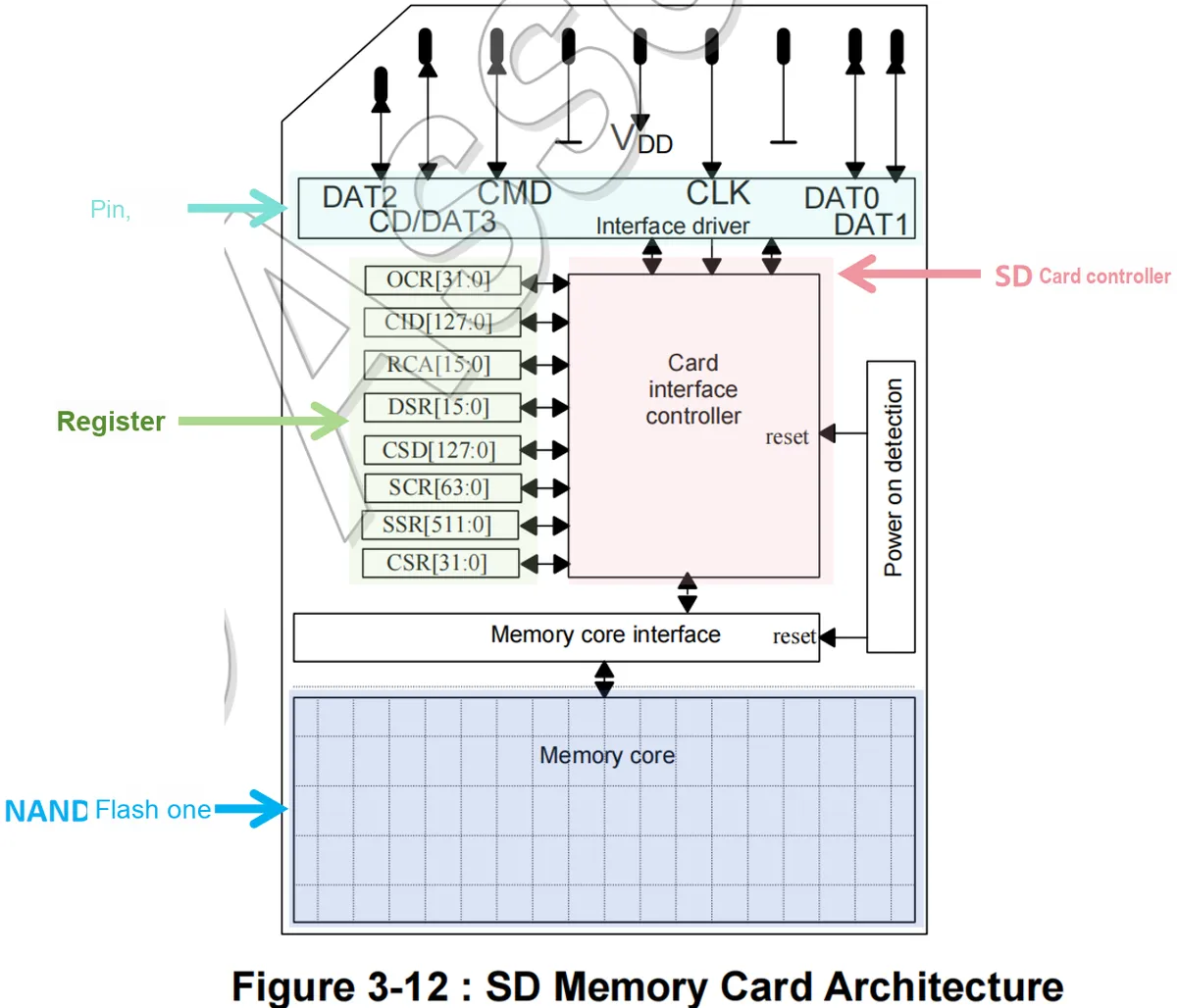
The internal structure of an SD card features a "hierarchical collaboration" design, with each component having clearly defined functions:
- Pin + Interface Driver: Corresponding to the "Pin" area in the diagram, this serves as the "connection cable interface" between the SD card and external devices (such as a development board), and is responsible for transmitting commands, data and power supply;
- SD Card Controller (Card interface controller) serves as the "intelligent central control unit" of the SD card, with its core functions as follows:
- Receive instructions from external devices (e. g., "read XX file", "check card information");
- Read / modify the information in the register;
- Manage the reading and writing of NAND flash memory;
- It performs functions such as wear leveling and error correction (to protect the lifespan and data of the card).
- Registers correspond to the "Registers" area in the diagram, which stores key information such as the identity, status, and capabilities of the SD card. The controller reads this information at any time, and external devices can also obtain this content via commands.
- NAND Flash (Memory core) serves as the "storage core" of an SD card, where all actual data (photos, files) is stored — it is equivalent to the "compartments" in a storage box, with read and write operations uniformly managed by the controller.
Below are some key registers and their functions:
| Register name | Simplified explanation | Core function |
|---|---|---|
| CID | Card "ID number" | Stores the SD card's unique identifier (different for every card, like a person's ID number) |
| RCA | Card "temporary address" | A "temporary number" generated when the SD card is initialized (lets the external device find it quickly; not used in SPI mode) |
| DSR | Card "output configuration table" | Configures the SD card's signal output strength (optional feature, beginners need not pay much attention) |
| CSD | Card "capability specification" | Stores the SD card's operating conditions and storage capabilities (e.g., maximum capacity, read/write speed limits) |
| SCR | Card "special function table" | Stores the SD card's special features (e.g., whether high-speed mode is supported) |
| OCR | Card "operating conditions table" | Stores the SD card's operating voltage range and whether it is currently ready (e.g., whether it works normally after power-up) |
| SSR | Card "proprietary feature table" | Stores the SD card's unique feature information (many details, generally not needed) |
| CSR | Card's "current status table" | Stores the SD card's real-time status (e.g., whether it is currently "read/write" or "read-only") |
The collaboration process between external devices (such as microcontrollers) and SD cards is as follows:
- External devices send commands to the SD card controller via "pins"(such as "read your identification number");
- The controller retrieves information from the corresponding register (e. g., CID) and transmits it back to the external device via the pins;
- When reading or writing data, the controller manages the "cells" of the NAND flash (allocating space, storing/retrieving data) in accordance with instructions;
- During this process, the controller employs "wear leveling"(storing data in different blocks in rotation to prevent any single block from wearing out prematurely) and "error correction"(automatically fixing minor errors in data) to protect the SD card and the stored data.
3.4.1.3 Operating Modes of SD Card
You can analogize the interaction between a host device (such as a development board or a mobile phone) and an SD card to "a mobile phone connecting to a new USB flash drive":
- Card identification mode: the process in which a mobile phone and a new USB flash drive "mutually recognize each other and prepare for pairing";
- Data Transfer Mode: The process in which a mobile phone stores files to or reads files from a USB flash drive after pairing is completed.
The operating modes of an SD card mainly consist of two phases: the Card Identification Mode and the Data Transfer Mode. In the Card Identification Mode, the host aims to identify and initialize the SD card to get it ready for entering the Data Transfer Mode, which is the actual phase for reading and writing data:
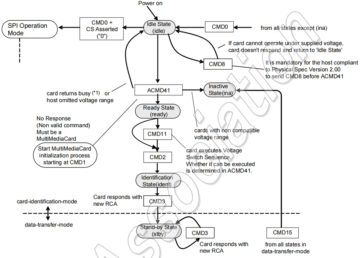
The "Idle/Ready/Ident" in the flowchart refers to the status (i. e., the current phase) of the SD card, while "CMD0/CMD8" are the commands sent by the host to the SD card. The entire process is as follows:
- Initial State: Idle
- When the SD card is inserted into the host (or powered on), the host will send "CMD0 (reset command)" — which is equivalent to the host saying: "Hello, reset yourself and get ready to start communication!";
- At this point, the SD card will enter the "idle state", select the operation mode (SPI mode or SD bus mode) at the same time, and wait for the next command from the host.
- Check voltage: Send CMD8
- The host sends "CMD8" — which is equivalent to asking: "Do you support the voltage I'm using here? ";
- If the SD card does not support this voltage, it will return to the idle state; if it does, it will proceed to the next step.
- Inquiry preparation: Send ACMD41
- The host sends "ACMD41" — which is equivalent to asking: "Are you ready? ";
- If the SD card is ready, it will enter the "Ready State"; if it is not ready, it will return a "busy" signal, and the host will wait for a while before querying again.
- Need "ID card": Send CMD2
- The host sends "CMD2" — which is equivalent to saying: "Send me your unique identifier (the CID register, just like an ID number)!";
- The SD card enters the "Identification State" and transmits its own CID (information such as manufacturer and serial number) to the host.
- Assign a "temporary number": send CMD3
- The host sends "CMD3" — which is equivalent to saying: "Here’s a temporary number (RCA, like a parcel pickup code) for you, I’ll refer to you by this later!";
- The SD card enters the "Stand-by State", and obtains this RCA to facilitate the host to quickly locate it subsequently.
- Selected card: Send CMD7 to enter data transfer mode
- The host sends "CMD7" — which is equivalent to saying: "I'm selecting you, get ready to start data transmission!";
- At this point, the SD card switches from "Card Identification Mode" to "Data Transfer Mode", and file read/write operations can commence.
In addition, there are some special procedures:
- If the SD card is an old MMC (MultiMediaCard), it will follow the "CMD1" procedure instead of using CMD8/ACMD41;
- "CMD15" is the "deselect card" command, which is equivalent to the host saying "I no longer need you", and the card will return to its previous state.
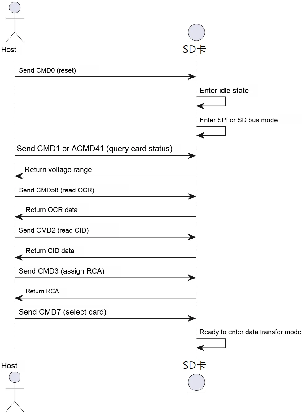
3.4.1.4 Communication Protocol and Command Response Model of SD Card
The Communication Protocol of the SD card mainly includes the SD bus protocol and the SPI protocol:
- SD Bus Protocol: It uses multiple data lines (typically 4 data lines) for parallel data transmission, supports various transmission speed classes such as SD, SDHC, SDXC, etc. , and performs data transmission by sending commands and parameters, where commands start with CMD;
- SPI Protocol: It uses 4 pins (CLK, MOSI, MISO, CS) for serial data transmission, commands are sent in single-byte format, and data is transmitted in the form of ByteFlow.
| SD bus protocol | Uses a CMD line + 4 data lines (DAT0~DAT3), with a CLK clock line, a VDD power line, and a VSS ground line | Supports parallel data transfer; bus width is configurable as 1-bit or 4-bit | Commands are transmitted in a 48-bit frame structure with check bits, supporting normal commands (CMD) and application-specific commands (ACMD) | Scenarios with high transfer rate requirements, such as consumer digital devices (cameras, phones) |
|---|---|---|---|---|
| SPI protocol | Uses 4 core pins (CLK clock line, MOSI master-out data, MISO slave-out data, CS chip select line) | Serial data transfer, supports half-duplex communication only | Commands use a single byte as the basic frame structure, and data is transferred as a continuous byte stream; the protocol is simplified, with no complex multi-line configuration | Embedded development scenarios with low hardware interface requirements, easy to implement through the MCU's SPI peripheral |
3.4.1.4.1 Command Response Model in SD Bus Protocol
SD card communication adopts a command-response mode, where the host sends commands to the SD card to initiate specific operations, and the SD card responds to the received commands; the commands CMD and responses RESPONSE are serially transmitted via the CMD line, while data DATA is transmitted via the data lines (DAT lines), ensuring that command and data transmission do not interfere with each other.
Instruction CMD is formatted as follows, including a start bit, transmission bits, command content (command and address information or parameters), and a stop bit:
The command frame of the SD bus protocol is of a fixed 48-bit length, and its frame structure is defined sequentially from the most significant bit to the least significant bit as follows:
- Start bit (1 bit): fixed at
0, indicating the start of the command frame; - Transmission bit (1 bit): fixed to
1, identifying this frame as a command from the host to the SD card; - Command code (6 bits): identifies the command type, e. g., CMD0 corresponds to
0x00, CMD2 corresponds to0x02; - Command parameters (32bit): Configuration information carried along with the command type, such as addresses, capacity parameters, status masks, etc. ;
- CRC check bit (7bit): Perform CRC7 check on the first 41 bits of data to ensure the correctness of command transmission;
- Stop bit (1 bit): fixed at
1, which marks the end of the command frame.
SD card commands are divided into two categories: standard commands (CMD) and application-specific commands (ACMD), which have distinct execution logics:
- Common Command (CMD): Can be sent directly by the host, and the SD card can parse and execute it without any precondition after receiving it;
- Application Command (ACMD): These are extended function commands specific to SD cards and cannot be sent directly. The host must first send CMD55, and only after receiving a valid response from the SD card can it send the ACMD; otherwise, the SD card will not recognize the command.
The commonly used general commands are as follows:
| Command code | Command name | Core function |
| CMD0 | GO_IDLE_STATE | Resets the SD card and puts it into the idle state, used to start the initialization process |
| CMD2 | ALL_SEND_CID | Instructs the SD card to send its own CID register data (unique card identifier) |
| CMD3 | SEND_RELATIVE_ADDR | The host assigns a relative address (RCA) to the SD card; the SD card returns this address and enters the standby state |
| CMD7 | SELECT/DESELECT_CARD | Selects or deselects the SD card by RCA; once selected, the card enters data transfer mode |
| CMD17 | READ_SINGLE_BLOCK | Instructs the SD card to read a single data block; the target block address parameter is required |
| CMD18 | READ_MULTIPLE_BLOCK | Instructs the SD card to read multiple data blocks continuously; CMD12 must be sent to stop the transfer |
| CMD24 | WRITE_BLOCK | Instructs the SD card to write a single data block; the target block address parameter is required |
| CMD25 | WRITE_MULTIPLE_BLOCK | Instructs the SD card to write multiple data blocks continuously; CMD12 must be sent to stop the transfer |
| CMD55 | APP_CMD | Notifies the SD card that an application-specific command (ACMD) will follow, providing the prerequisite for ACMD execution |
The following is a list of common ACMD commands in the SD card protocol:
After receiving a valid command, the SD card must return a response frame via the CMD line. Response frames are categorized into 4 standard types by function and length, with four encoding schemes depending on content, and have a length of either 48 bits or 136 bits:
Here, we summarize the common response types of SD cards:
| Response type | Length | Key features and uses |
| R1 | 48 | The most commonly used response type; contains the SD card's current status bits (such as idle, ready, error states, etc.) and is used for the responses to most CMD commands (such as CMD0, CMD3, CMD55) |
| R2 | 136 | Long response frame, used to return SD card register data, such as the responses to CMD2 (returns CID) and CMD9 (returns CSD) |
| R3 | 48 | Used to return OCR register data, corresponds only to the CMD1/ACMD41 commands, and carries key information such as the card's operating voltage range and capacity type flag |
| R4 | 48 | Used for specific command responses in SPI protocol mode, carrying the SD card's status and configuration parameters |
It should be noted that all response frames contain CRC check bits, and the host can only determine that the response is valid after verifying that the CRC is correct.
Data transmission of the SD card is based on the block transfer mechanism, the data frame format is related to the bus width, and it supports two modes: single-block transmission and multi-block transmission.
Wherein:
- Single Block Transmission: Triggered by the host via CMD17 (read) / CMD24 (write) commands, the SD card only transmits 1 single data block, and the transmission ends automatically upon completion without requiring an additional termination command;
- Multiple Block Transmission: Triggered by the host via CMD18 (read) / CMD25 (write) commands, the SD card continuously transmits multiple data blocks, and the data transmission will not terminate until the host sends CMD12 (stop transmission command). This mode is suitable for continuous reading and writing of large files and can improve transmission efficiency.
Data frame transmission is divided into two modes: normal data transmission and wide data transmission, which correspond to different bus widths.
- Ordinary data transmission: adopts a 1-wire bus (only DAT0), transmits data serially in units of bytes, each byte contains 8 data bits, together with a start bit, a stop bit and CRC16 check bits, and is suitable for low-speed transmission scenarios;
- Wide Data Transmission: It adopts a 4-wire bus (DAT0~DAT3), splits 1 byte (8 bits) of data into 4 groups with 2 bits per group for parallel transmission via the 4 data lines, delivers a transmission rate 4 times that of the 1-wire mode, and is applicable to high-speed transmission scenarios.
3.4.1.4.2 Command Response Model in SPI Protocol
Similar to the SD bus protocol, the SPI protocol also consists of commands, responses, and data block markers. All communication between the host and the card is controlled by the host (master device), which initiates each transmission transaction by pulling the CS signal low. The data blocks in SPI can be as large as a write block or as small as a single byte; for SDHC and SDXC cards, the block length is fixed at 512 bytes. It should be noted that the write protection commands (CMD28, CMD29, and CMD30) are not supported in SPI mode.
In SPI mode, the card initialization process is as follows:
- Power-on and Mode Selection: After power-on, the SD card enters
Idle State, and the host sendsCMD0(reset command):- If the CS signal is pulled low (
CS Asserted), the SD card enters the SPI Operation Mode; - Otherwise, enter the SD bus mode.
- If the CS signal is pulled low (
- Voltage Compatibility Check: Hosts complying with the Version 2.00 specification shall send
CMD8:- If the SD card returns "Non supported voltage range", the host will stop accessing it;
- If voltage support is available, send
CMD58to read the OCR register and obtain the voltage range supported by the SD card.
- SD Card Initialization: Host sends
ACMD41(CMD55 must be sent first):- If the SD card returns "busy"(shown as "card is busy" in the diagram), it indicates that the card is undergoing internal initialization, and the host needs to wait until the card is ready.
- After initialization is complete, the host can
CMD58read the OCR again to confirm the card capacity information (CCS identifier).
- Validity Check: If the SD card does not respond to
CMD8/ACMD41, it will be determined as "Not SD Memory Card", and the host will stop the operation.
In SPI mode, the SD card supports Single Block Read and Multiple Block Read operations, which correspond respectively to CMD17 and CMD18 commands in the SD card protocol:
The timing sequence is: Host (DataIn) → Send CMD17 command → SD card (DataOut) → Return R1 response → SD card sends data block + CRC → Transaction ends.
The timing sequence is as follows: Host (DataIn) → sends CMD18 command → SD card (DataOut) → returns R1 response → SD card continuously sends multiple data blocks + CRC → Host sends CMD12 (stop command) → SD card returns R1 response → Transaction ends.
Similarly, SD cards support Single Block Write and Multiple Block Write commands, which correspond respectively to CMD24 and CMD25 commands in the SD card protocol:
Host (DataIn) → sends CMD24 command → SD card (DataOut) → returns R1 response → Host sends start block token + data block → SD card returns data response + busy signal (indicating writing in progress) → Transaction ends.
Host (DataIn) → sends CMD25 command → SD card (DataOut) → returns R1 response → Host continuously sends start block token + multiple data blocks → Host sends stop token → SD card returns busy signal → Transaction ends.
In SPI mode, the formats of commands, responses and data of the SD card are different from those in the standard SD mode. Each command is 6 bytes long, starting from 01 (start bit), followed by the command number (6 bits), then a 32-bit parameter, and finally a 7-bit CRC check and a 1-bit stop bit:

| Bit position | Length (bits) | Field | Description |
| 47 | 1 | Start bit | Fixed to 0 |
| 46 | 1 | Transmission bit | Fixed to 1 (indicates host → SD card) |
| 21:40 | 6 | Command index | 6-bit command number (e.g., CMD0 corresponds to 0x00) |
| 15:08 | 32 | Parameter | Configuration information carried with the command (e.g., block address) |
| 7:01 | 7 | CRC7 | CRC7 checksum of the first 41 bits |
| 0 | 1 | Stop bit | Fixed to 1 |
For specific command functions and parameters, please refer to Table 7-3: Commands and Arguments in the SD card specification:
| Command index | SPI support | Core function | Response type |
| CMD0 | Yes | Reset the SD card and enter idle state | R1 |
| CMD8 | Yes | Send voltage condition, check compatibility | R7 |
| CMD17 | Yes | Single-block read | R1 |
| CMD18 | Yes | Multi-block read | R1 |
| CMD24 | Yes | Single-block write | R1 |
| CMD25 | Yes | Multi-block write | R1 |
| CMD55 | Yes | Indicates the following command is an ACMD command | R1 |
| CMD58 | Yes | Read the OCR register | R3 |
Application Commands ACMD For the functions and parameters, please refer to Table 7-4 in the specification: Application Specific Commands used/reserved by SD Memory Card - SPI Mode:
Response RESPONSE is typically 1 byte, referred to as the R1 response; in some cases, a response of 2 bytes or more may be required.
The structure of the R1 response is shown in the following figure, which includes an idle state indication bit, an erase reset indication bit, an illegal command indication bit, etc. :
The R2 response consists of 2 bytes: the first byte is R1, and the second byte contains additional error flags and some other flags.
The R3 response is used for OCR register read, and contains the R1 response and OCR data:
There is also an R7 response, which corresponds to the SEND_IF_COND command (CMD8). This response is 5 bytes long: the first byte has the same structure as the R1-type response, used to indicate the command status and error information, while the remaining four bytes contain the card's operating voltage information and the echo of the check pattern:
The different responses are compared as follows:
| Response type | R1 response | R2 response | R3 response | R7 response |
| Length | 1 byte | 2 bytes | 5 bytes | 5 bytes |
| Structure | 8 bits: Bit 0 = parameter error Bit 1 = address error Bit 2 = erase sequence error Bit 3 = command CRC error Bit 4 = illegal command Bit 5 = erase reset Bit 6 = idle state Bit 7 = fixed to 0 | 2 bytes: Byte 1 = R1 response Byte 2 = extended status (card locked, write protect violation, etc.) | 5 bytes: Byte 1 = R1 response Bytes 2-5 = OCR register data (operating voltage, capacity identifier) | 5 bytes: Byte 1 = R1 response Bytes 2-5 = voltage accepted flag + check pattern echo (corresponds to the CMD8 argument) |
| Purpose | Response to most CMD commands; indicates the current state of the SD card | Response when returning CID/CSD register data | Response to the CMD58 command; returns OCR register information | Response to the CMD8 command; checks voltage compatibility |
A data token is the unit that carries the actual data in SD card read and write operations, and its general structure follows the format of "start flag + data + checksum", while complying with fixed transmission rules:
- Components:
- Start Flag (1 byte): identifies the start of a data block (different values correspond to single-block and multi-block scenarios);
- Data Field (2 to 513 bytes): the user data actually stored (fixed at 512 bytes for SDHC/SDXC cards);
- Checksum (2 bytes): A 16-bit CRC16 check value used to verify the correctness of data transmission.
- Transmission Rules:
- The byte transmission order is MSB first (the higher-order byte is transmitted first);
- The data length is adjustable depending on the card type (1~512 bytes for standard SD cards, fixed at 512 bytes for SDHC/SDXC cards).
Depending on the type of read/write operation (single-block or multi-block), the start flag of the data token uses different values to correspond to different transmission scenarios:
| Operation scenario | Start flag (1 byte) | Binary format (corresponds to the figure) | Data segment length | Checksum | Applicable commands |
|---|---|---|---|---|---|
| Single-block read / write | 0xFE | 11111110 (Figure 1: bits 7-1 are 1, bit 0 is 0) | 2~513 bytes (fixed at 512 bytes for SDHC/SDXC) | 2-byte CRC16 | CMD17 (single-block read), CMD24 (single-block write) |
| Start of multi-block read / write | 0xFC | 11111100 (Figure 2: Start Block Token) | 2~513 bytes (fixed at 512 bytes for SDHC/SDXC) | 2-byte CRC16 | CMD18 (multi-block read), CMD25 (multi-block write) |
| Terminate multi-block transfer | 0xFD | 11111101 ( Figure 2: Stop Tran Token) | - (no data field) | - | Used with CMD12 to terminate multi-block transfer |
When performing write and read operations on multiple data tokens, first use 0xFC to mark the start of a data token, and use 0xFD at the end of data transmission:
After the data transmission is completed, the SD card feeds back the result via a response token/error token:
| Feedback type | Token format (1 byte) | Function description | Applicable scenarios |
| Data response token | Bits 7-4: any value; Bit 4 = 0; Bits 3-1 = status bits; Bit 0 = 1 (Figure 3) | Reports the result of the data write | After single-block write and multi-block write operations |
| Data error token | Bits 7-4 = 0000; Bits 3-0 = error bits (Figure 4) | Reports the reason a read operation failed (same as the error bits in the R2 response) | When a read operation fails |
Here is the data response token:
The definition of the status bits is as follows:
- '010': Data accepted
- '101': Data rejected due to CRC error
- '110': Data rejected due to write error
In multi-block write operations, if any error occurs (CRC error or write error), the host shall stop the data transmission with CMD12; if a write error occurs (with a response of '110'), the host may send CMD13 (SEND_STATUS) to obtain the cause of the write issue, or identify the number of successfully written blocks via ACMD22.
If a read operation fails and the SD card cannot provide the required data, the card will send a 1-byte data error token, whose format is as follows:
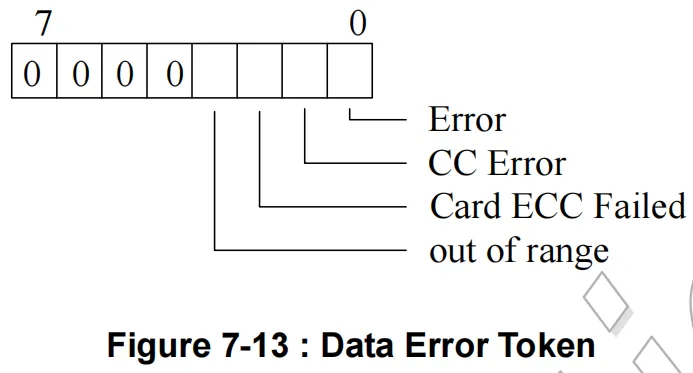
Among them, the 4 least significant bits (LSB) are the same as the error bits in the R2 response format, indicating different error states.
3.4.1.5 Introduction to the Storage Structure of SD Card
Through an external communication interface (SD bus or SPI bus), we can access the memory cells of an SD card:
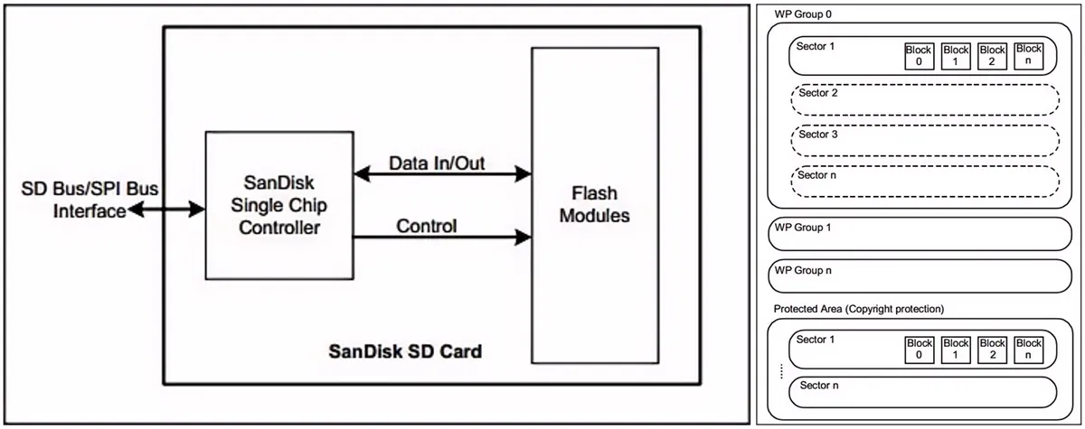
The storage structure of an SD card consists of two parts: the internal hardware architecture and the logical/physical storage units.
- Internal hardware architecture of SD card: Consists of a single-chip controller and a Flash memory module, which work together to realize data communication and storage:
- Single Chip Controller (SanDisk Single Chip Controller): it serves as the "control hub" of the SD card.
- External Description: Establish communication with external hosts (e. g. development boards) via the "SD Bus/SPI Bus Interface";
- Internal: Manage the read and write logic of the Flash storage module via the "Control" signal, and transmit data with the Flash module through the "Data In/Out" interface simultaneously.
- Flash Memory Modules (Flash Modules): they serve as the "actual storage medium" of an SD card, where all user data is stored, and their read and write operations are uniformly scheduled by the controller.
- Single Chip Controller (SanDisk Single Chip Controller): it serves as the "control hub" of the SD card.
- Core Units of Storage: The storage units of an SD card are divided into logically addressable units (Sectors) and physical storage units (Blocks); the definitions and relationship between the two are as follows:
- Sector
- It is the smallest addressable unit of an SD card (when the host accesses the SD card, it can only take the Sector as the minimum operation granularity);
- The size is usually 512 bytes;
- Each Sector contains multiple Blocks (a Block is the basic unit of physical storage).
- Block
- It is the basic physical unit for an SD card to write data to the Flash memory module;
- The size is usually 512 bytes or 4KB;
- When writing actual data, the controller organizes the data into Blocks before writing them to the Flash module.
- Sector
- Write Protection and Dedicated Areas: The core consists of "Write Protection Groups" and "Protected Areas":
- Write Protection Group (WP Group)
- It is the logical area for the SD card to implement the write protection function, with sectors as the basic unit;
- When the SD card is in a write-protected state, all sectors within the WP Group are prohibited from being written to or modified (such as WP Group 0, WP Group 1, etc. in the figure on the right).
- Protected Area
- It is a dedicated storage area for copyright protection, which also takes sectors as the unit;
- Access to this area is restricted by the SD card protocol, and unauthorized hosts cannot modify the data stored therein.
- Write Protection Group (WP Group)
- Internal Buffer: An SD card has a built-in temporary data buffer, whose core functions are as follows:
- temporarily stores data waiting to be read or written, so as to reduce direct read and write operations on the Flash storage module (and thus lower the erase and write wear of Flash);
- Batch scheduling of data transmission to improve overall read and write efficiency (for example, when the host reads and writes data continuously, the Buffer can temporarily store the data and then interact with the Flash in a unified manner).
3.4.2 Implementation of Custom SD Card Read/Write Class
In the following code, we implement functions such as SD card initialization, command sending, and data reading, and interact with the SD card through the SPI communication interface to ensure that the card can work properly.
The sample code is as follows:
# Python env   : MicroPython v1.23.0
# -*- coding: utf-8 -*-
# @Time    : 2024/9/30 PM 12:11
# @Author  : Li Qingshui
# @File    : sdcard.py
# @Description : Custom SDCard class for SD card reading and writing
# Reference code: https://github.com/micropython/micropython-lib/blob/master/micropython/drivers/storage/sdcard/sdcard.py#L291

# ======================================== Import Modules ========================================

# Import MicroPython-related modules
from micropython import const
# Import time-related modules
import time
# Import hardware-related modules
from machine import SPI, Pin

# ======================================== Global Variables ============================================

# Define SD card related constants
CMD_TIMEOUT = const(100)            # Command timeout constant
R1_IDLE_STATE = const(1 << 0)       # R1 response status: idle state
R1_ILLEGAL_COMMAND = const(1 << 2)  # R1 response status: illegal command
TOKEN_CMD25 = const(0xFC)           # Data transfer command token
TOKEN_STOP_TRAN = const(0xFD)       # Stop transmission token
TOKEN_DATA = const(0xFE)            # Data token

# ======================================== Functions ============================================

# ======================================== Custom Classes ============================================

# Custom SD card operation class
class SDCard:
    """
    SDCard class, used to operate SD/MMC memory cards over the SPI bus.
    This class encapsulates the low-level SD card communication protocol and supports initialization of standard capacity cards (SDSC) and high capacity cards (SDHC/SDXC),
    block read/write and erase operations. It implements the complete SPI-mode protocol stack, including card identification mode and data transfer mode.

    Attributes:
        spi (SPI): SPI interface instance, used to communicate with the SD card
        cs (Pin): Chip select pin instance, used to select the SD card
        sectors (int): Total number of sectors on the card (read-only)
        cdv (int): Block addressing factor (1 means block addressing, 512 means byte addressing)
        cmdbuf (bytearray): Command buffer (6 bytes)
        dummybuf (bytearray): Data buffer (512 bytes)
        tokenbuf (bytearray): Token buffer (1 byte)

    Methods:
        __init__(self, spi: machine.SPI, cs: machine.Pin, baudrate: int = 1320000) -> None:
            Initialize the SD card controller

        init_spi(self, baudrate: int) -> None:
            Configure SPI interface parameters

        init_card(self, baudrate: int) -> None:
            Execute the complete initialization procedure

        cmd(self, cmd: int, arg: int, crc: int, final: int = 0, release: bool = True, skip1: bool = False) -> int:
            Send an SD card command and get the response

        readinto(self, buf: bytearray) -> None:
            Read a data block into the buffer

        write(self, token: int, buf: bytearray) -> bool:
            Write a data block to the card

        write_token(self, token: int) -> None:
            Send a control token

        erase_block(self, block_number: int) -> None:
            Erase the specified data block

        init_card_v1(self) -> None:
            Initialize a standard capacity SD card

        init_card_v2(self) -> None:
            Initialize a high capacity SD card

    Constants:
        CMD_TIMEOUT: Number of command timeout retries (100)
        R1_IDLE_STATE: Card idle state flag (0x01)
        R1_ILLEGAL_COMMAND: Illegal command flag (0x04)
        TOKEN_CMD25: Multi-block write start token (0xFC)
        TOKEN_STOP_TRAN: Stop transmission token (0xFD)
        TOKEN_DATA: Single-block data token (0xFE)
    """
    def __init__(self, spi: SPI, cs: Pin, baudrate: int = 1320000) -> None:
        """
        Initialize the SD card controller.

        Args:
            spi (machine.SPI): Configured SPI interface object
            cs (machine.Pin): Chip select pin object
            baudrate (int, optional): SPI baud rate, default 1320000

        Returns:
            None

        Raises:
            OSError: If a hardware error occurs during initialization
            ValueError: If the baud rate is out of the valid range
        """
        # Store the SPI interface
        self.spi = spi
        # Store the CS pin
        self.cs = cs

        # Create the command buffer, 6 bytes long
        self.cmdbuf = bytearray(6)
        # Create the dummy data buffer, 512 bytes long
        self.dummybuf = bytearray(512)
        # Create the token buffer, 1 byte long
        self.tokenbuf = bytearray(1)

        # Initialize the dummy data buffer to all FF
        for i in range(512):
            self.dummybuf[i] = 0xFF

        # Create a memory view of the dummy data buffer
        self.dummybuf_memoryview = memoryview(self.dummybuf)

        # Initialize the SD card
        self.init_card(baudrate)

    def init_spi(self, baudrate: int) -> None:
        """
        Configure the SPI interface parameters.

        Args:
            baudrate (int): Target communication rate (Hz)

        Returns:
            None

        Raises:
            ValueError: If the baud rate is out of the range supported by the hardware
        """
        # Initialize SPI
        self.spi.init(baudrate=baudrate, phase=0, polarity=0)

    def init_card(self, baudrate: int) -> None:
        """
        Perform the complete SD card initialization sequence.

        Args:
            baudrate (int): Target data transfer baud rate

        Returns:
            None

        Raises:
            OSError: If any of the following occurs:
                - Card does not respond
                - Version identification fails
                - CSD format is not supported
                - Block size setting fails
        """
        # Initialize the CS pin, set the CS pin to output high
        self.cs.init(self.cs.OUT, value=1)

        # Initialize the SPI bus; initialize at a low data rate
        self.init_spi(100000)

        # Idle cycles before sending commands, keep CS high
        for i in range(16):
            # Send 16 null bytes
            self.spi.write(b"\xff")

        # CMD0: Initialize the card; should return _IDLE_STATE (5 attempts allowed)
        for _ in range(5):
            if self.cmd(0, 0, 0x95) == R1_IDLE_STATE:
                break
        else:
            # If no SD card is found, raise an exception
            raise OSError("no SD card")

        # CMD8: Determine the card version
        r = self.cmd(8, 0x01AA, 0x87, 4)
        if r == R1_IDLE_STATE:
            # Initialize a v2 card
            self.init_card_v2()
        elif r == (R1_IDLE_STATE | R1_ILLEGAL_COMMAND):
            # Initialize a v1 card
            self.init_card_v1()
        else:
            # Unable to determine the SD card version
            raise OSError("couldn't determine SD card version")

        # Get the number of sectors
        # CMD9: Response R2 (R1 byte + 16-byte block read)
        if self.cmd(9, 0, 0, 0, False) != 0:
            # If there is no response, raise an exception
            raise OSError("no response from SD card")

        # Create the CSD buffer
        csd = bytearray(16)
        # Read the CSD data
        self.readinto(csd)

        # CSD version 2.0
        if csd[0] & 0xC0 == 0x40:
            # Calculate the number of sectors
            self.sectors = ((csd[8] << 8 | csd[9]) + 1) * 1024
            # CSD version 1.0 (old, <=2GB)
        elif csd[0] & 0xC0 == 0x00:
            # Get C_SIZE
            c_size = (csd[6] & 0b11) << 10 | csd[7] << 2 | csd[8] >> 6
            # Get C_SIZE_MULT
            c_size_mult = (csd[9] & 0b11) << 1 | csd[10] >> 7
            # Get the read block length
            read_bl_len = csd[5] & 0b1111
            # Calculate the capacity
            capacity = (c_size + 1) * (2 ** (c_size_mult + 2)) * (2**read_bl_len)
            # Calculate the number of sectors
            self.sectors = capacity // 512
        else:
            # Unsupported CSD format
            raise OSError("SD card CSD format not supported")

        # CMD16: Set the block length to 512 bytes
        if self.cmd(16, 512, 0) != 0:
            # Unable to set the block size
            raise OSError("can't set 512 block size")

        # Now switch to a high data rate
        self.init_spi(baudrate)

    def init_card_v1(self) -> None:
        """
        Initialize a standard capacity SD card (SDSC).

        Args:
            None

        Returns:
            None

        Raises:
            OSError: If initialization times out (100 attempts)
        """
        for i in range(CMD_TIMEOUT):
            time.sleep_ms(50)
            # Send command 55
            self.cmd(55, 0, 0)

            # Try to initialize the card
            # SDSC card, use byte addressing for read/write/erase commands
            if self.cmd(41, 0, 0) == 0:
                # Set the block size to 512 bytes
                self.cdv = 512
                # Return on success
                return
        # Raise an exception on timeout
        raise OSError("timeout waiting for v1 card")

    def init_card_v2(self) -> None:
        """
        Initialize a high capacity SD card (SDHC/SDXC).

        Args:
            None

        Returns:
            None

        Raises:
            OSError: If initialization times out (100 attempts)
        """
        for i in range(CMD_TIMEOUT):
            # Wait 50 ms
            time.sleep_ms(50)
            # Send command 58 to get the OCR
            self.cmd(58, 0, 0, 4)
            # Send command 55 to prepare for initialization
            self.cmd(55, 0, 0)

            # Try to initialize the SDHC/SDXC card
            if self.cmd(41, 0x40000000, 0) == 0:
                # 4-byte response, a negative value means keep the first byte
                self.cmd(58, 0, 0, -4)
                # Get the first byte of the OCR
                ocr = self.tokenbuf[0]
                # SDSC card, use byte addressing
                if not ocr & 0x40:
                    # Set the block size to 512 bytes
                    self.cdv = 512
                else:
                    # SDHC/SDXC card, use block addressing
                    # Set the block size to 1 byte
                    self.cdv = 1
                # Return on success
                return

        # Raise an exception on timeout
        raise OSError("timeout waiting for v2 card")

    def cmd(self, cmd: int, arg: int, crc: int, final: int = 0, release: bool = True, skip1: bool = False) -> int:
        """
        Send an SD card command and get the response.

        Args:
            cmd (int): Command number (0-63)
            arg (int): 32-bit command argument
            crc (int): CRC check value
            final (int, optional): Number of extra bytes to read, default 0
            release (bool, optional): Whether to release CS, default True
            skip1 (bool, optional): Whether to skip the first byte, default False

        Returns:
            int: Response status:
                - 0x00: Normal
                - 0x01: Idle state
                - -1: Timeout

        Raises:
            OSError: If SPI communication fails
        """
        # Pull the CS pin low to start communication
        self.cs(0)

        # Create and send the command
        buf = self.cmdbuf

        # Set the command header
        buf[0] = 0x40 | cmd
        # Set the command argument (high byte)
        buf[1] = arg >> 24
        # Set the command argument (second-highest byte)
        buf[2] = arg >> 16
        # Set the command argument (second-lowest byte)
        buf[3] = arg >> 8
        # Set the command argument (low byte)
        buf[4] = arg
        # Set the CRC check
        buf[5] = crc

        # Send the command over SPI
        self.spi.write(buf)

        # If the first response needs to be skipped
        if skip1:
            # Read one byte and discard it
            self.spi.readinto(self.tokenbuf, 0xFF)

        # Wait for the response (response[7] == 0)
        for i in range(CMD_TIMEOUT):
            # Read the response byte
            self.spi.readinto(self.tokenbuf, 0xFF)
            # Get the response
            response = self.tokenbuf[0]

            # Check whether the response is valid
            if not (response & 0x80):
                # Handle the big-endian integer case
                # If final is negative
                if final < 0:
                    # Read and discard one byte
                    self.spi.readinto(self.tokenbuf, 0xFF)
                    # Update the final value
                    final = -1 - final

                # Read the extra bytes
                for j in range(final):
                    # Send a null byte to maintain timing
                    self.spi.write(b"\xff")

                # If the CS signal needs to be released
                if release:
                    # Pull the CS pin high
                    self.cs(1)
                    # Send a null byte
                    self.spi.write(b"\xff")
                # Return the valid response
                return response

        # Timeout handling
        # Pull the CS pin high
        self.cs(1)
        # Send a null byte
        self.spi.write(b"\xff")
        # Return -1 to indicate timeout
        return -1

    def readinto(self, buf: bytearray) -> None:
        """
        Read a data block into the buffer.

        Args:
            buf (bytearray): Target buffer (must be 512 bytes)

        Returns:
            None

        Raises:
            ValueError: If the buffer length is wrong
            OSError: If the read times out or the check fails
        """
        # Pull the CS pin low to start communication
        self.cs(0)

        # Read until the start byte (0xff)
        for i in range(CMD_TIMEOUT):
            # Read one byte
            self.spi.readinto(self.tokenbuf, 0xFF)
            # Check whether it is the data start token
            if self.tokenbuf[0] == TOKEN_DATA:
                # Found the start byte, exit the loop
                break
            # Wait 1 ms
            time.sleep_ms(1)
        else:
            # Pull the CS pin high
            self.cs(1)
            # Raise a timeout error
            raise OSError("timeout waiting for response")

        # Read data, create a memory view
        mv = self.dummybuf_memoryview
        # If the buffer length does not match
        if len(buf) != len(mv):
            # Slice to the buffer length
            mv = mv[: len(buf)]
        # Read data into buf
        self.spi.write_readinto(mv, buf)

        # Send a null byte
        self.spi.write(b"\xff")
        self.spi.write(b"\xff")

        # Pull the CS pin high
        self.cs(1)
        # Send a null byte
        self.spi.write(b"\xff")

    def write(self, token: int, buf: bytearray) -> bool:
        """
        Write a data block to the card.

        Args:
            token (int): Write token (0xFC/0xFD/0xFE)
            buf (bytearray): Source data (must be 512 bytes)

        Returns:
            bool: Write result:
                - True: Success
                - False: Failure

        Raises:
            ValueError: If the data length is wrong
            OSError: If the card responds abnormally
        """
        # Pull the CS pin low to start communication
        self.cs(0)

        # Send: block start marker, data, checksum
        self.spi.read(1, token)
        self.spi.write(buf)
        self.spi.write(b"\xff")
        self.spi.write(b"\xff")

        # Check whether the response is the success flag
        if (self.spi.read(1, 0xFF)[0] & 0x1F) != 0x05:
            # Pull the CS pin high
            self.cs(1)
            # Send a null byte
            self.spi.write(b"\xff")
            # Return, write failed
            return

        # Wait for the write to complete
        while self.spi.read(1, 0xFF)[0] == 0:
            # Wait until the write is complete
            pass

        # Pull the CS pin high
        self.cs(1)
        # Send a null byte
        self.spi.write(b"\xff")

    def write_token(self, token: int) -> None:
        """
        Send a control token.

        Args:
            token (int): Control token (0xFC/0xFD/0xFE)

        Returns:
            None

        Raises:
            OSError: If the card does not respond
        """
        # Pull the CS pin low to start communication
        self.cs(0)
        # Send the marker
        self.spi.read(1, token)
        # Send a null byte
        self.spi.write(b"\xff")

        # Wait for the write to complete
        while self.spi.read(1, 0xFF)[0] == 0x00:
            # Wait until the write is complete
            pass

        # Pull the CS pin high
        self.cs(1)
        # Send a null byte
        self.spi.write(b"\xff")

    def erase_block(self, block_number: int) -> None:
        """
        Erase the specified data blocks.

        Args:
            block_number (int): Block number (LBA format)

        Returns:
            None

        Raises:
            ValueError: If the block number is out of range
            OSError: If the erase command fails
        """
        # Pull the CS pin low to start communication
        self.cs(0)

        # Send erase commands CMD32 (erase start) and CMD33 (erase end)
        # Start erase
        self.cmd(32, block_number * 512, 0)
        # End erase
        self.cmd(33, block_number * 512, 0)

        # Send erase command CMD38 (erase)
        self.cmd(38, 0, 0)

        # Wait for the erase to complete
        while True:
            # Query status
            response = self.cmd(13, 0, 0)
            # Erase complete
            if response == 0:
                break

        # Pull the CS pin high
        self.cs(1)
        # Send a null byte
        self.spi.write(b"\xff")

# ======================================== Initialization ==========================================

# ========================================  Main Program  ============================================
memoryview memory view
memoryview is a memory view object provided by Python, which allows accessing and manipulating mutable buffer objects (such as bytearray, bytes, array.array) without copying data. Its main function is to improve data processing efficiency and reduce unnecessary memory usage.
In Python, when working with binary data (such as bytearray):
- Direct slicing creates a copy of the data, which consumes additional memory.
memoryviewallows direct manipulation of the original data, avoiding copying and improving performance.
In the classes mentioned above, if you directly use bytearray, each slicing operation (such as dummybuf[: len (buf)]) will create a new copy, which impacts performance; in contrast, memoryview directly references the original data without making copies.
For more information about memoryview, please refer to the following document: https://docs.python.org/3.5/library/stdtypes.html#memoryview
3.4.2.1 Initialization Method
In the custom SDCard class, initialization is performed first: configure SPI communication and the CS pin, and create multiple buffers to support subsequent operations:
def __init__(self, spi: SPI, cs: Pin, baudrate: int = 1320000) -> None:
    """
    Initialize the SD card controller.

    Args:
        spi (machine.SPI): Configured SPI interface object
        cs (machine.Pin): Chip select pin object
        baudrate (int, optional): SPI baud rate, default 1320000

    Returns:
        None

    Raises:
        OSError: If a hardware error occurs during initialization
        ValueError: If the baud rate is out of the valid range
    """
    # Store the SPI interface
    self.spi = spi
    # Store the CS pin
    self.cs = cs

    # Create the command buffer, 6 bytes long
    self.cmdbuf = bytearray(6)
    # Create the dummy data buffer, 512 bytes long
    self.dummybuf = bytearray(512)
    # Create the token buffer, 1 byte long
    self.tokenbuf = bytearray(1)

    # Initialize the dummy data buffer to all FF
    for i in range(512):
        self.dummybuf[i] = 0xFF

    # Create a memory view of the dummy data buffer
    self.dummybuf_memoryview = memoryview(self.dummybuf)

    # Initialize the SD card
    self.init_card(baudrate)
The specific workflow is as follows:
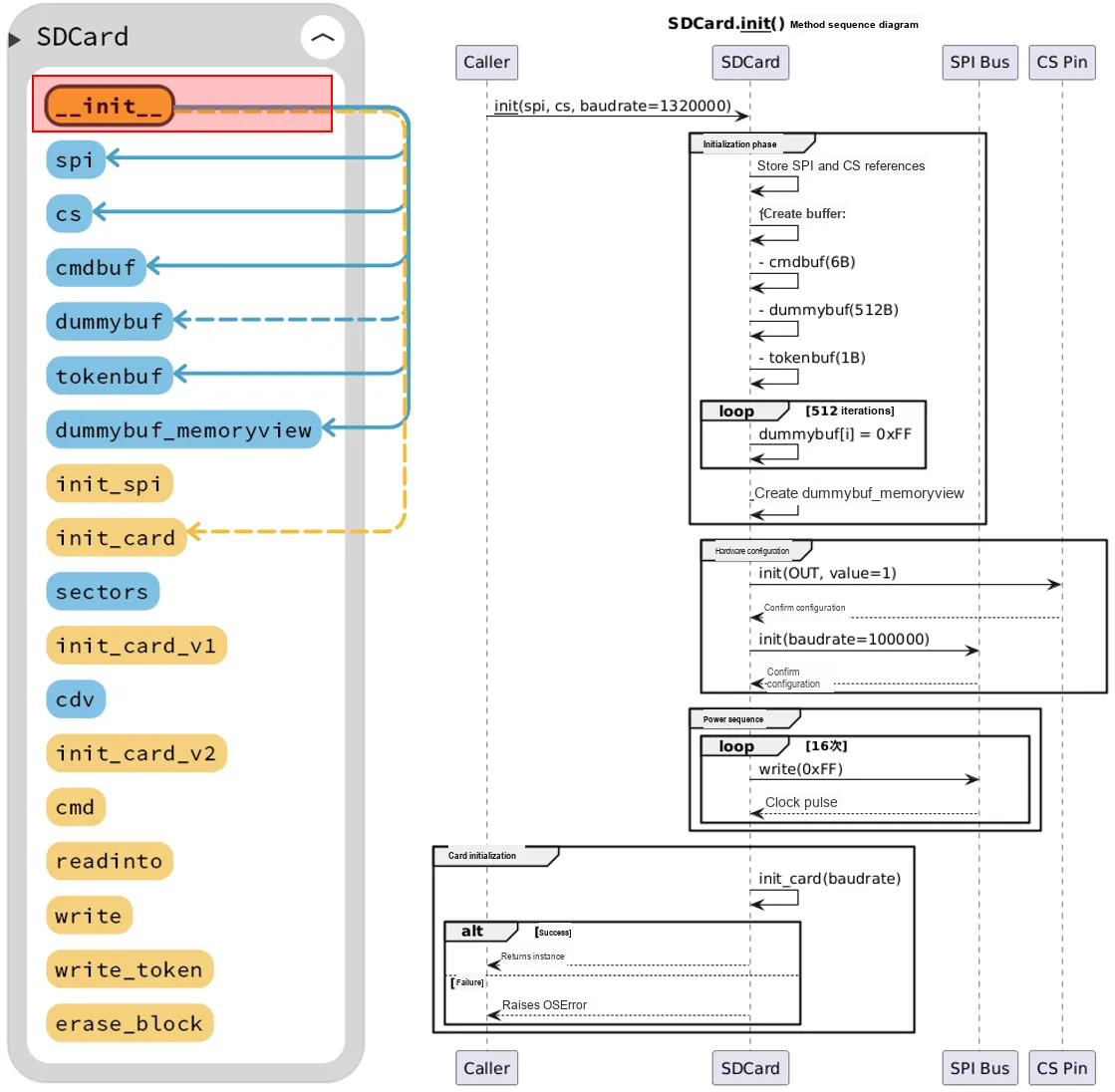
The actual method for initializing the SD card is the init_card method, and this function is responsible for detecting and initializing the SD card as well as determining the card type (SDSC or SDHC/SDXC):
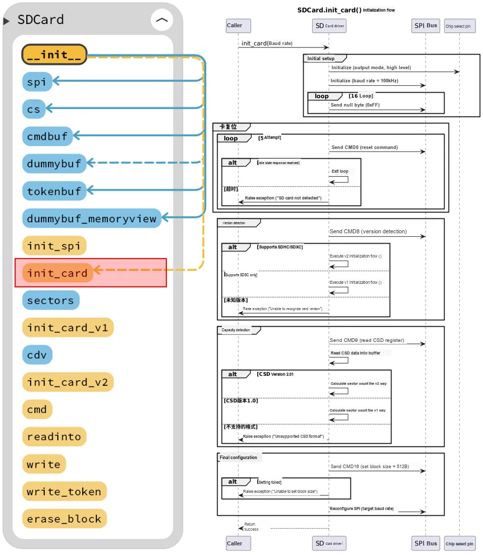
First, set the chip select pin CS to high level (1), indicating that the SD card is not selected:
def init_card(self, baudrate: int) -> None:
    """
    Perform the complete SD card initialization sequence.

    Args:
        baudrate (int): Target data transfer baud rate

    Returns:
        None

    Raises:
        OSError: If any of the following occurs:
            - Card does not respond
            - Version identification fails
            - CSD format is not supported
            - Block size setting fails
    """
    # Initialize the CS pin, set the CS pin to output high
    self.cs.init(self.cs.OUT, value=1)
Then initialize the SPI at a low speed (100kHz), since the SD card requires low-speed communication after power-on:
# Initialize the SPI bus; initialize at a low data rate
self.init_spi(100000)
Then send 16 bytes 0xFF to allow the SD card to complete its internal power-on and enter the SPI communication mode:
# Idle cycles before sending commands, keep CS high
for i in range(16):
    # Send 16 null bytes
    self.spi.write(b"\xff")
Then send CMD0 in a loop for 5 times to enter SPI mode, and throw OSError ("no SD card") if the expected response is not obtained.
Then send CMD8 to check the SD version:
# CMD8: Determine the card version
r = self.cmd(8, 0x01AA, 0x87, 4)
if r == R1_IDLE_STATE:
    # Initialize a v2 card
    self.init_card_v2()
elif r == (R1_IDLE_STATE | R1_ILLEGAL_COMMAND):
    # Initialize a v1 card
    self.init_card_v1()
else:
    # Unable to determine the SD card version
raise OSError("couldn't determine SD card version")- If
R1_IDLE_STATE (0x01)is returned, it indicates a new version SD card, and callself.init_card_v2 (); - If the return value is
R1_ILLEGAL_COMMAND (0x04), it indicates a legacy SD card, and callself.init_card_v1 (); - If neither is the case, throw an exception
"couldn't determine SD card version".
New SD cards (≥2GB) support either block addressing mode or byte addressing mode, and the init_card_v2 () function performs the following operations: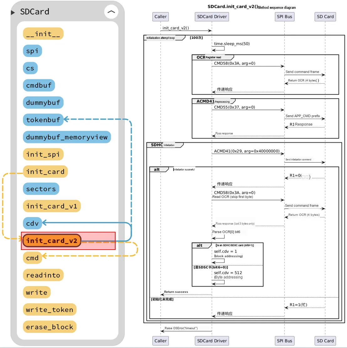
def init_card_v2(self) -> None:
    """
    Initialize a high capacity SD card (SDHC/SDXC).

    Args:
        None

    Returns:
        None

    Raises:
        OSError: If initialization times out (100 attempts)
    """
    for i in range(CMD_TIMEOUT):
        # Wait 50 ms
        time.sleep_ms(50)
        # Send command 58 to get the OCR
        self.cmd(58, 0, 0, 4)
        # Send command 55 to prepare for initialization
        self.cmd(55, 0, 0)

        # Try to initialize the SDHC/SDXC card
        if self.cmd(41, 0x40000000, 0) == 0:
            # 4-byte response, a negative value means keep the first byte
            self.cmd(58, 0, 0, -4)
            # Get the first byte of the OCR
            ocr = self.tokenbuf[0]
            # SDSC card, use byte addressing
            if not ocr & 0x40:
                # Set the block size to 512 bytes
                self.cdv = 512
            else:
                # SDHC/SDXC card, use block addressing
                # Set the block size to 1 byte
                self.cdv = 1
            # Return on success
            return

    # Raise an exception on timeout
raise OSError("timeout waiting for v2 card")- First send
CMD58to read the OCR register (to confirm whether it is SDHC/SDXC); - then send
CMD55 + CMD41commands to perform SDHC/SDXC initialization; - If it is confirmed to be an SDSC card (byte addressing), set the block addressing factor
cdv = 512; - If it is confirmed that the card is an SDHC/SDXC card (block addressing), set the block addressing factor
cdv = 1.
Legacy SD cards (≤2GB) all use byte addressing mode, send CMD55 + CMD41 in a loop to wait for the SD card to complete initialization, then set the block addressing factor cdv = 1:
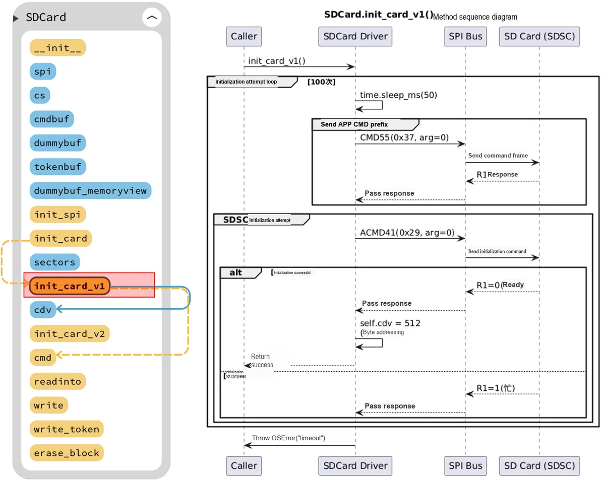
def init_card_v1(self) -> None:
    """
    Initialize a standard capacity SD card (SDSC).

    Args:
        None

    Returns:
        None

    Raises:
        OSError: If initialization times out (100 attempts)
    """
    for i in range(CMD_TIMEOUT):
        time.sleep_ms(50)
        # Send command 55
        self.cmd(55, 0, 0)

        # Try to initialize the card
        # SDSC card, use byte addressing for read/write/erase commands
        if self.cmd(41, 0, 0) == 0:
            # Set the block size to 512 bytes
            self.cdv = 512
            # Return on success
            return
    # Raise an exception on timeout
    raise OSError("timeout waiting for v1 card")
Then the init_card method sends CMD9 (to read the 16-byte CSD register data) to obtain capacity information:
# Get the number of sectors
# CMD9: Response R2 (R1 byte + 16-byte block read)
if self.cmd(9, 0, 0, 0, False) != 0:
    # If there is no response, raise an exception
    raise OSError("no response from SD card")

# Create the CSD buffer
csd = bytearray(16)
# Read the CSD data
self.readinto(csd)
Then calculate the number of sectors of the SD card:
# CSD version 2.0
if csd[0] & 0xC0 == 0x40:
    # Calculate the number of sectors
    self.sectors = ((csd[8] << 8 | csd[9]) + 1) * 1024
    # CSD version 1.0 (old, <=2GB)
elif csd[0] & 0xC0 == 0x00:
    # Get C_SIZE
    c_size = (csd[6] & 0b11) << 10 | csd[7] << 2 | csd[8] >> 6
    # Get C_SIZE_MULT
    c_size_mult = (csd[9] & 0b11) << 1 | csd[10] >> 7
    # Get the read block length
    read_bl_len = csd[5] & 0b1111
    # Calculate the capacity
    capacity = (c_size + 1) * (2 ** (c_size_mult + 2)) * (2**read_bl_len)
    # Calculate the number of sectors
    self.sectors = capacity // 512
else:
    # Unsupported CSD format
raise OSError("SD card CSD format not supported")- If it is an SDSC card, you can directly read the register data to calculate the number of sectors;
- If it is an SDHC/SDXC card, it is necessary to calculate the byte capacity and convert it to the number of sectors.
After setting the block length to 512 bytes, the initialization is completed, and the SPI settings are adjusted to achieve a high data transfer rate:
# CMD16: Set the block length to 512 bytes
if self.cmd(16, 512, 0) != 0:
    # Unable to set the block size
    raise OSError("can't set 512 block size")

# Now switch to a high data rate
self.init_spi(baudrate)
3.4.2.2 Command Sending Method
The cmd method is used to send commands to the SD card and obtain responses, and the entire process can be divided into five main stages: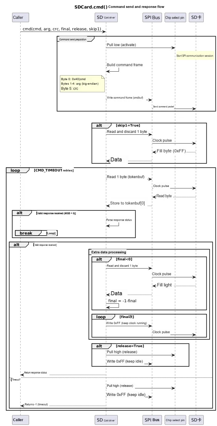
- Pull down the CS (Chip Select) pin to initiate SPI communication;
- Construct and send the command;
- Wait for the SD card to respond (return
-1on timeout); - Read optional additional data;
- Release CS and return the response.
Here, we first pull the CS pin low to start communication, then construct a command buffer containing the command number, parameters and CRC check value, and send the command via SPI:
def cmd(self, cmd: int, arg: int, crc: int, final: int = 0, release: bool = True, skip1: bool = False) -> int:
    """
    Send an SD card command and get the response.

    Args:
        cmd (int): Command number (0-63)
        arg (int): 32-bit command argument
        crc (int): CRC check value
        final (int, optional): Number of extra bytes to read, default 0
        release (bool, optional): Whether to release CS, default True
        skip1 (bool, optional): Whether to skip the first byte, default False

    Returns:
        int: Response status:
            - 0x00: Normal
            - 0x01: Idle state
            - -1: Timeout

    Raises:
        OSError: If SPI communication fails
    """
    # Pull the CS pin low to start communication
    self.cs(0)

    # Create and send the command
    buf = self.cmdbuf

    # Set the command header
    buf[0] = 0x40 | cmd
    # Set the command argument (high byte)
    buf[1] = arg >> 24
    # Set the command argument (second-highest byte)
    buf[2] = arg >> 16
    # Set the command argument (second-lowest byte)
    buf[3] = arg >> 8
    # Set the command argument (low byte)
    buf[4] = arg
    # Set the CRC check
    buf[5] = crc

    # Send the command over SPI
    self.spi.write(buf)
If the option to skip the first response is enabled, the first byte will be discarded. Then, the system enters a loop to read the response from the SD card until a valid response is received or a timeout occurs. If the response is valid, any additional bytes will be read as required and the CS signal will be deasserted:
# If the first response needs to be skipped
if skip1:
    # Read one byte and discard it
    self.spi.readinto(self.tokenbuf, 0xFF)

# Wait for the response (response[7] == 0)
for i in range(CMD_TIMEOUT):
    # Read the response byte
    self.spi.readinto(self.tokenbuf, 0xFF)
    # Get the response
    response = self.tokenbuf[0]

    # Check whether the response is valid
    if not (response & 0x80):
        # Handle the big-endian integer case
        # If final is negative
        if final < 0:
            # Read and discard one byte
            self.spi.readinto(self.tokenbuf, 0xFF)
            # Update the final value
            final = -1 - final

        # Read the extra bytes
        for j in range(final):
            # Send a null byte to maintain timing
            self.spi.write(b"\xff")

        # If the CS signal needs to be released
        if release:
            # Pull the CS pin high
            self.cs(1)
            # Send a null byte
            self.spi.write(b"\xff")
        # Return the valid response
        return response
Finally, the response bytes of the SD card are returned, or -1 is returned in case of a timeout:
# Timeout handling
# Pull the CS pin high
self.cs(1)
# Send a null byte
self.spi.write(b"\xff")
# Return -1 to indicate timeout
return -1
3.4.2.3 Data Block Reading Method
The readinto method is used to read a 512-byte data block from the SD card and store it into the specified buffer. First, pull the CS pin low to initiate communication, then enter a loop to continuously read bytes until the data start marker (0xFF) is detected. If the start byte is not found within the set timeout period, pull the CS pin high and throw a timeout error:
def readinto(self, buf: bytearray) -> None:
    """
    Read a data block into the buffer.

    Args:
        buf (bytearray): Target buffer (must be 512 bytes)

    Returns:
        None

    Raises:
        ValueError: If the buffer length is wrong
        OSError: If the read times out or the check fails
    """
    # Pull the CS pin low to start communication
    self.cs(0)

    # Read until the start byte (0xff)
    for i in range(CMD_TIMEOUT):
        # Read one byte
        self.spi.readinto(self.tokenbuf, 0xFF)
        # Check whether it is the data start token
        if self.tokenbuf[0] == TOKEN_DATA:
            # Found the start byte, exit the loop
            break
        # Wait 1 ms
        time.sleep_ms(1)
    else:
        # Pull the CS pin high
        self.cs(1)
        # Raise a timeout error
        raise OSError("timeout waiting for response")
After finding the start byte, create a memory view and check whether the length of the buffer matches; if not, perform slicing. Then, read data from the SD card into the provided buffer via SPI and send two null bytes:
# Read data, create a memory view
mv = self.dummybuf_memoryview
# If the buffer length does not match
if len(buf) != len(mv):
    # Slice to the buffer length
    mv = mv[: len(buf)]
# Read data into buf
self.spi.write_readinto(mv, buf)

# Send a null byte
self.spi.write(b"\xff")
self.spi.write(b"\xff")

# Pull the CS pin high
self.cs(1)
# Send a null byte
self.spi.write(b"\xff")
The overall Sequence Diagram is shown as follows:
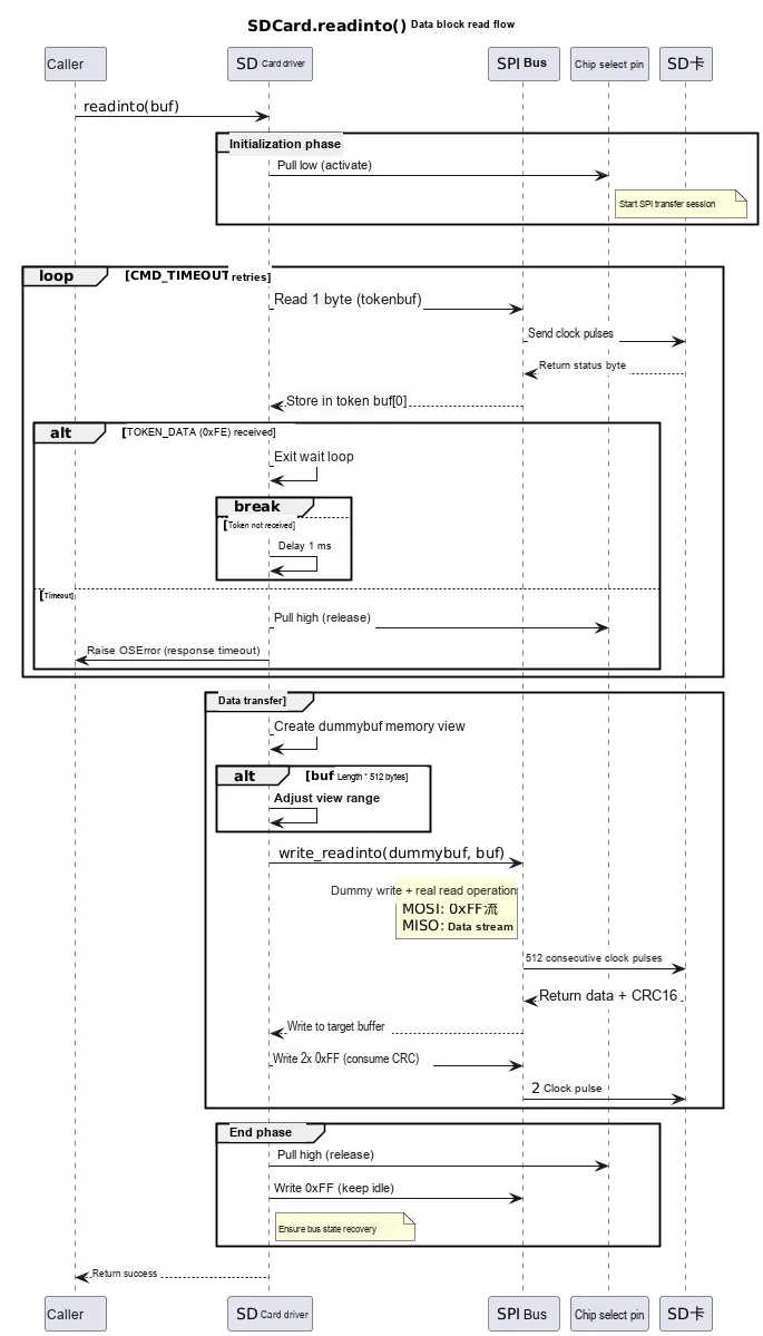
3.4.2.4 Data Block Reading Method
The write method is used to write a 512-byte data block to the SD card. First, pull the CS pin low to start communication, then send the write start token, data, and two null bytes:
def write(self, token: int, buf: bytearray) -> bool:
    """
    Write a data block to the card.

    Args:
        token (int): Write token (0xFC/0xFD/0xFE)
        buf (bytearray): Source data (must be 512 bytes)

    Returns:
        bool: Write result:
            - True: Success
            - False: Failure

    Raises:
        ValueError: If the data length is wrong
        OSError: If the card responds abnormally
    """
    # Pull the CS pin low to start communication
    self.cs(0)

    # Send: block start marker, data, checksum
    self.spi.read(1, token)
    self.spi.write(buf)
    self.spi.write(b"\xff")
    self.spi.write(b"\xff")
Next, check the response to confirm whether the write operation is successful. If the response does not match the success flag, pull the CS pin high, send a null byte and then return; if the response indicates success, the method will wait until the write operation is completed:
# Check whether the response is the success flag
if (self.spi.read(1, 0xFF)[0] & 0x1F) != 0x05:
    # Pull the CS pin high
    self.cs(1)
    # Send a null byte
    self.spi.write(b"\xff")
    # Return, write failed
    return

# Wait for the write to complete
while self.spi.read(1, 0xFF)[0] == 0:
    # Wait until the write is complete
    pass
After completion, pull the CS pin high again and send a null byte to terminate the communication:
# Pull the CS pin high
self.cs(1)
# Send a null byte
self.spi.write(b"\xff")
The overall Sequence Diagram is shown as follows:
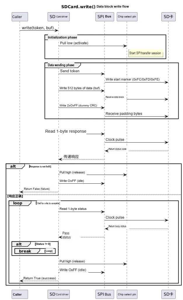
3.4.2.5 Data Token Writing Method
write_token method is used to send a control token and wait for the SD card to complete internal operations. First, pull the CS pin low, send the start token and a null byte, then wait for the write operation to finish; finally, pull the CS pin high and send a null byte to terminate the communication:
def write_token(self, token: int) -> None:
    """
    Send a control token.

    Args:
        token (int): Control token (0xFC/0xFD/0xFE)

    Returns:
        None

    Raises:
        OSError: If the card does not respond
    """
    # Pull the CS pin low to start communication
    self.cs(0)
    # Send the marker
    self.spi.read(1, token)
    # Send a null byte
    self.spi.write(b"\xff")

    # Wait for the write to complete
    while self.spi.read(1, 0xFF)[0] == 0x00:
        # Wait until the write is complete
        pass

    # Pull the CS pin high
    self.cs(1)
    # Send a null byte
    self.spi.write(b"\xff")
3.4.2.6 Data Erasure Method
erase_block method is used to erase the specified data block on the SD card. First, pull the CS pin low to initiate communication, then send the erase commands CMD32 (erase start) and CMD33 (erase end) to specify the block number to be erased, and convert the block number to a byte offset by multiplying it by 512:
def erase_block(self, block_number: int) -> None:
    """
    Erase the specified data blocks.

    Args:
        block_number (int): Block number (LBA format)

    Returns:
        None

    Raises:
        ValueError: If the block number is out of range
        OSError: If the erase command fails
    """
    # Pull the CS pin low to start communication
    self.cs(0)

    # Send erase commands CMD32 (erase start) and CMD33 (erase end)
    # Start erase
    self.cmd(32, block_number * 512, 0)
    # End erase
    self.cmd(33, block_number * 512, 0)
Next, send CMD38 (erase command) to actually perform the erase operation, then enter a loop to continuously query the erase status by sending the CMD13 command until the return value is 0, which indicates that the erase is completed; finally, pull up the CS pin and send a dummy byte to terminate the communication:
# Wait for the erase to complete
while True:
    # Query status
    response = self.cmd(13, 0, 0)
    # Erase complete
    if response == 0:
        break

# Pull the CS pin high
self.cs(1)
# Send a null byte
self.spi.write(b"\xff")
3.4.3 SD Card Mounting File System
In the following code, we implement the operations of initializing the SD card and mounting it as a file system, and create a CSV file to write the website name and URL data. A CSV file can be thought of as a simple spreadsheet, but it does not have the rich functions and complex formats of Excel; instead, it is just a text file separated by commas. Each line in a CSV represents a record, the fields in a record are separated by commas, and its data is stored in plain text:
3.4.3.1 Preparations before the experiment
First, we need to insert the Fengya No. 1 Board - Ethernet and SD Card Expansion Board into the Fengya No. 1 Board - Universal Compatible Expansion Board, and set all the SW1 DIP switches on the Fengya No. 1 Board - Ethernet and SD Card Expansion Board to the ON position.
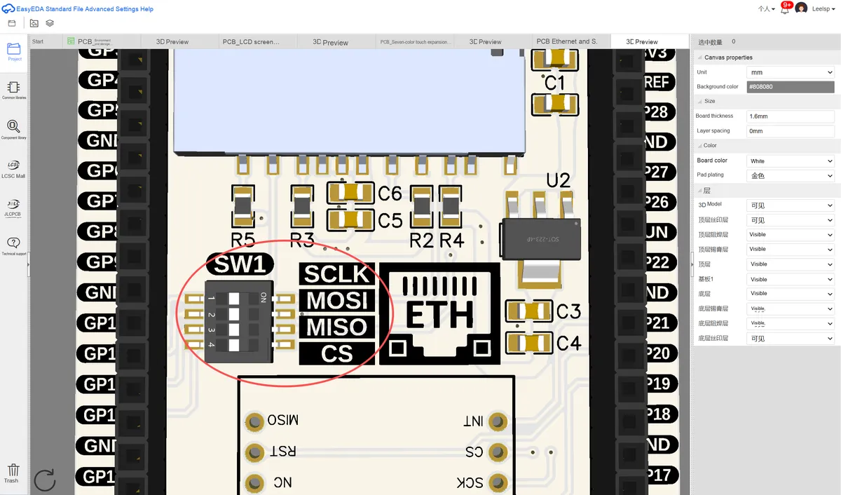
In addition, we also need to insert the SD card into the SD card slot on the SD card module. The SD card slot is equipped with internal electrical connections and control circuits, which can connect the SD card to the microcontroller.
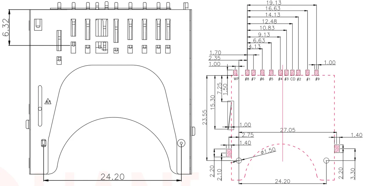
The functions of each pin are as follows:
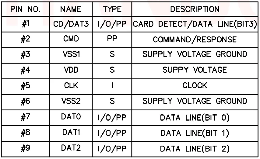
The function of each pin and its role in SPI mode are as follows:
Pin Number | Pin Name | Roles in SPI Mode |
Pin1 | DAT3/CS | chip select signal |
Pin2 | CMD/MOSI | Master output, slave input |
Pin5 | CLK/SCLK | SPI clock signal |
Pin7 | DAT0/MISO | Master input, slave output |
Pin4 | VDD/+3V3 | power supply |
Pin3 | VSS/GND | grounding |
For the rest, the other VSS pin Pin 6 needs to be grounded, while Pin 8 and Pin 9 need to be connected to a high level. It should be noted that the SPI bus MOSI, MISO, SCK and CS signals require pull-up resistors to ensure they remain at a high level when not being driven. Additionally, for the VDD power supply section, a 0.1µF ceramic capacitor and a 10µF electrolytic capacitor should be connected to filter the power supply.
The circuit schematic diagram is shown as follows:
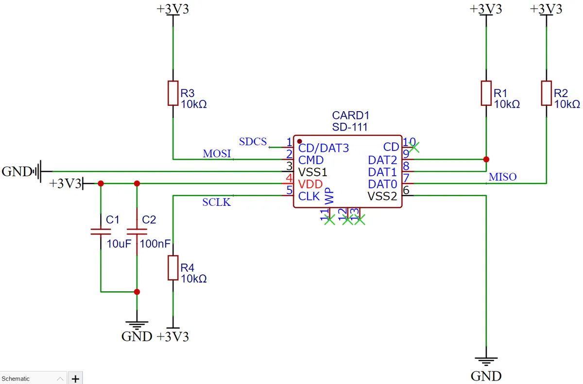
The physical picture is shown as follows:
The connection between the SD card slot and the Raspberry Pi Pico is shown in the following table:
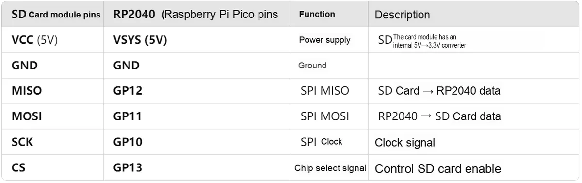
3.4.3.2 Implementation of SD Card Block Device Class
To implement file system mounting on an SD card, we first need to implement the block device required by the VFS (Virtual File System). Here, we have defined a SDCARDBlockDevice class for block device operations with the SD card, which provides functions for reading, writing, controlling and managing data blocks of the SD card. The sample code is as follows:
# Python env   : MicroPython v1.23.0
# -*- coding: utf-8 -*-
# @Time    : 2024/10/1 AM 11:13
# @Author  : Li Qingshui
# @File    : sd_block_dev.py
# @Description : Custom SD card block device class
# Reference code: https://github.com/micropython/micropython-lib/blob/master/micropython/drivers/storage/sdcard/sdcard.py#L291

# ======================================== Import Modules ========================================

# Import the abstract base class of the virtual file block device
from AbstractBlockDevInterface import AbstractBlockDev
# Import some constants defined in the custom SD card read/write class
from sdcard import TOKEN_CMD25,TOKEN_STOP_TRAN,TOKEN_DATA
# Import the custom SD card read/write class
from sdcard import SDCard

# ======================================== Global Variables ============================================

# Define error code constants, conforming to POSIX standard error codes
ENOERR = 0       # Operation successful
EPERM = 1        # Operation not permitted
EIO = 5          # I/O error
ENODEV = 19      # Invalid device/block number
EROFS = 30       # Read-only file system
EINVAL = 22      # Invalid argument
ENOSPC = 28      # No space

# ======================================== Functions ============================================

# ======================================== Custom Classes ============================================

class SDCARDBlockDevice(AbstractBlockDev):
    """
    SDCARDBlockDevice class, implements read and write operations for an SD card block device.

    This class inherits from AbstractBlockDev and wraps block-level read and write operations on an SDCard device,
    providing the standard readblocks, writeblocks and ioctl methods, conforming to the MicroPython block device interface specification.

    Attributes:
        sdcard (SDCard): The associated SDCard instance, used to perform the actual SD card operations.

    Methods:
        __init__(self, sdcard: SDCard):
            Initialize an SDCARDBlockDevice instance and bind it to an SDCard device.

        readblocks(self, block_num: int, buf: bytearray, offset: int = 0):
            Read the data of one or more blocks from the SD card into a buffer.

        writeblocks(self, block_num: int, buf: bytearray, offset: int = 0):
            Write the buffer data to one or more blocks of the SD card.

        ioctl(self, op: int, arg: int) -> int:
            Device control interface, used to perform operations such as initialization, synchronization and getting block information.
    """
    def __init__(self, sdcard: SDCard) -> None:
        """
        Initialize an SDCARDBlockDevice instance.

        Args:
            sdcard (SDCard): The SDCard instance passed in.

        Raises:
            ValueError: If the sdcard passed in is not an SDCard instance.
        """

        # Check whether the SDCard instance passed in is valid
        if not isinstance(sdcard, SDCard):
            raise ValueError("Invalid SDCard instance")

        # Call the parent class constructor
        super().__init__()

        # Save the SDCard instance passed in
        self.sdcard = sdcard

    def readblocks(self, block_num: int, buf: bytearray, offset: int = 0) -> None:
        """
        Read data blocks from the SD card into a buffer.

        Args:
            block_num (int): Starting block number.
            buf (bytearray): Buffer used to store the read data; its length must be a multiple of 512 bytes.
            offset (int, optional): Data offset, default is 0.

        Raises:
            OSError: If the buffer length is not a multiple of 512, or the read fails.
        """
        # Check whether the buffer is valid and its length is 512 bytes
        if not buf or len(buf) % 512 != 0:
            raise OSError(EINVAL, "Buffer length must be multiple of 512")

        # Work around the shared bus issue: make sure MOSI is high before starting the transaction
        self.sdcard.spi.write(b"\xff")

        # Calculate the number of blocks to read
        nblocks = len(buf) // 512
        # Make sure the buffer length is valid
        assert nblocks and not len(buf) % 512, "Buffer length is invalid"

        if nblocks == 1:
            # CMD17: Set the read address of a single block
            if self.sdcard.cmd(17, block_num * self.sdcard.cdv, 0, release=False) != 0:
                # Release the card
                self.sdcard.cs(1)
                # EIO error
                raise OSError(EIO, "Failed to read singe block")
            # Receive data and release the card
            self.sdcard.readinto(buf)
        else:
            # CMD18: Set the read address of multiple blocks
            if self.sdcard.cmd(18, block_num * self.sdcard.cdv, 0, release=False) != 0:
                # Release the card
                self.sdcard.cs(1)
                # EIO error
                raise OSError(EIO, "Failed to read multi blocks")
            # Data offset
            offset = 0

            # Create a memory view
            mv = memoryview(buf)
            while nblocks:
                # Receive data and release the card
                self.sdcard.readinto(mv[offset : offset + 512])
                # Update the offset
                offset += 512
                # Decrease the remaining block count
                nblocks -= 1
            if self.sdcard.cmd(12, 0, 0xFF, skip1=True):
                # EIO error
                raise OSError(EIO, "Failed to stop multi blocks")

    def writeblocks(self, block_num: int, buf: bytearray, offset: int = 0) -> None:
        """
        Write data blocks from a buffer to the SD card.

        Args:
            block_num (int): Starting block number.
            buf (bytearray): Data to write; its length must be a multiple of 512 bytes.
            offset (int, optional): Data offset, default is 0.

        Raises:
            OSError: If the buffer length is not a multiple of 512, or the write fails.
        """
        # Check whether the buffer is valid and its length is 512 bytes
        if not buf or len(buf) % 512 != 0:
            raise OSError(EINVAL, "Buffer length must be multiple of 512")

        # Work around the shared bus issue: make sure MOSI is high before starting the transaction
        self.sdcard.spi.write(b"\xff")

        # Calculate the number of blocks to write
        nblocks, err = divmod(len(buf), 512)
        # Make sure the buffer length is valid
        assert nblocks and not err, "Buffer length is invalid"
        if nblocks == 1:
            # CMD24: Set the write address of a single block
            if self.sdcard.cmd(24, block_num * self.sdcard.cdv, 0) != 0:
                # EIO error
                raise OSError(EIO, "Failed to write singe block")

            # Send the data
            self.sdcard.write(TOKEN_DATA, buf)
        else:
            # CMD25: Set the write address of the first block
            if self.sdcard.cmd(25, block_num * self.sdcard.cdv, 0) != 0:
                # EIO error
                raise OSError(EIO, "Failed to write multi blocks")

            # Send the data
            offset = 0

            # Create a memory view
            mv = memoryview(buf)
            while nblocks:
                # Send each block of data
                self.sdcard.write(TOKEN_CMD25, mv[offset : offset + 512])
                # Update the offset
                offset += 512
                # Decrease the remaining block count
                nblocks -= 1
            # Send the stop transmission command
            self.sdcard.write_token(TOKEN_STOP_TRAN)

    def ioctl(self, op: int, arg: int) -> int:
        """
        Control the block device and query its parameters.

        Args:
            op (int): Operation code, see the AbstractBlockDev definition.
            arg (int): Additional argument.

        Returns:
            int: Operation result; returns 0 on success, or the corresponding block count/byte count.

        Raises:
            OSError: If the operation code is invalid or the erase block number is invalid.
        """
        # Initialize the device
        if op == AbstractBlockDev.IOCTL_INIT:
            # Perform the initialization operation
            self.sdcard.init_card(1320000)
            # Return 0 on success
            return ENOERR
        # Shut down the device
        elif op == AbstractBlockDev.IOCTL_SHUTDOWN:
            return ENOERR
        # Synchronize the device
        elif op == AbstractBlockDev.IOCTL_SYNC:
            return ENOERR
        # Get the number of blocks
        elif op == AbstractBlockDev.IOCTL_BLK_COUNT:
            # Return the number of sectors
            return self.sdcard.sectors
        # Get the block size (in bytes)
        elif op == AbstractBlockDev.IOCTL_BLK_SIZE:
            # Return 512 bytes
            return 512
        # Erase a block
        elif op == AbstractBlockDev.IOCTL_BLK_ERASE:
            # Erase the specified block
            if arg < 0 or arg >= self.sdcard.sectors:
                # If the block number is invalid, raise an error
                raise OSError(ENOSPC, "Invalid block number")
            self.sdcard.erase_block(arg)
            return ENOERR
        else:
            # Invalid operation code, raise an exception
            raise OSError(EINVAL, "Invalid ioctl operation")

# ======================================== Initialization ==========================================

# ========================================  Main Program  ============================================
This class provides the following methods:
- Initialization: In the constructor
init, the passed-inSDCardinstance is saved as an object property for invocation in subsequent methods. Initialization is performed by calling the parent class constructor. - Read data blocks
readblocksMethod: Used to read data blocks from the SD card into the provided buffer. Depending on the number of blocks to be read, theCMD17command is used to read a single block, or theCMD18command is used to read multiple blocks. During the reading process, ensure that the MOSI signal is at a high level; then calculate the starting address for reading based on the block number, call the method of the SD card instance to perform the actual data reading, and release the card after the reading is completed.
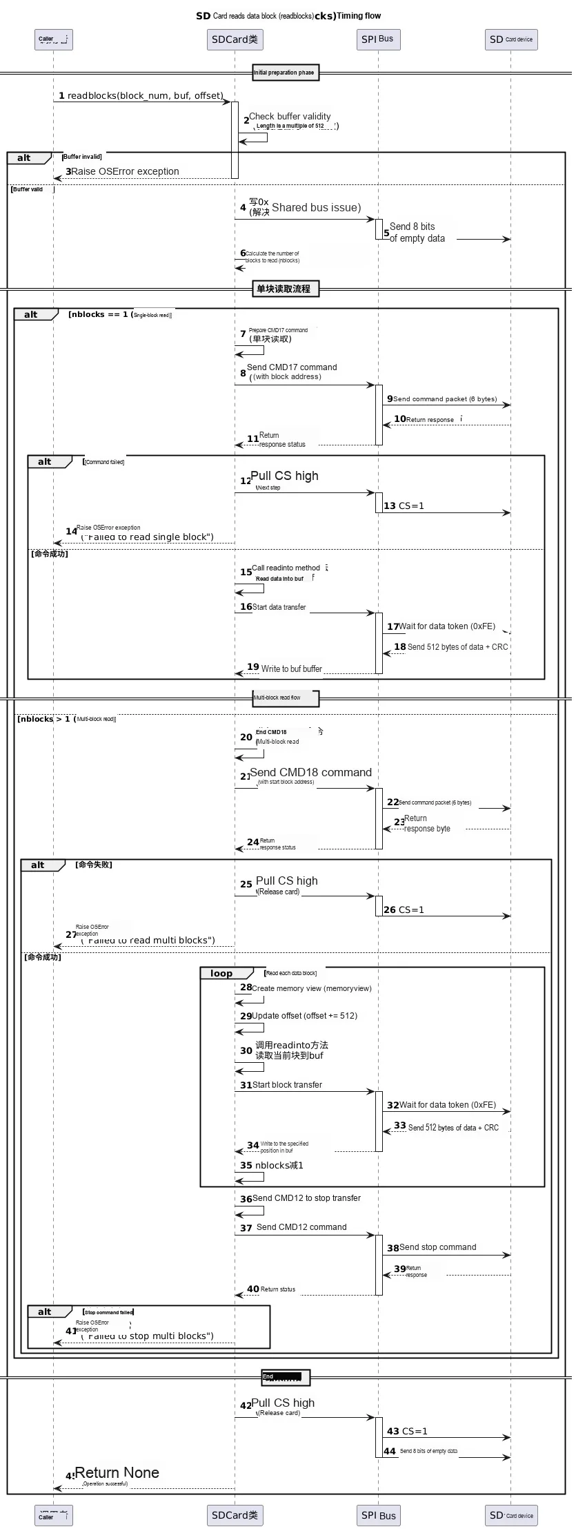
- Write data block
writeblocksMethod: Used to write the data in the buffer to the SD card. Depending on the number of blocks to be written, theCMD24command is used to write a single block, or theCMD25command is used to write multiple blocks; calculate the number of blocks to be written, perform data writing through the method of the SD card instance, and finally send a stop transmission command to end the write operation.
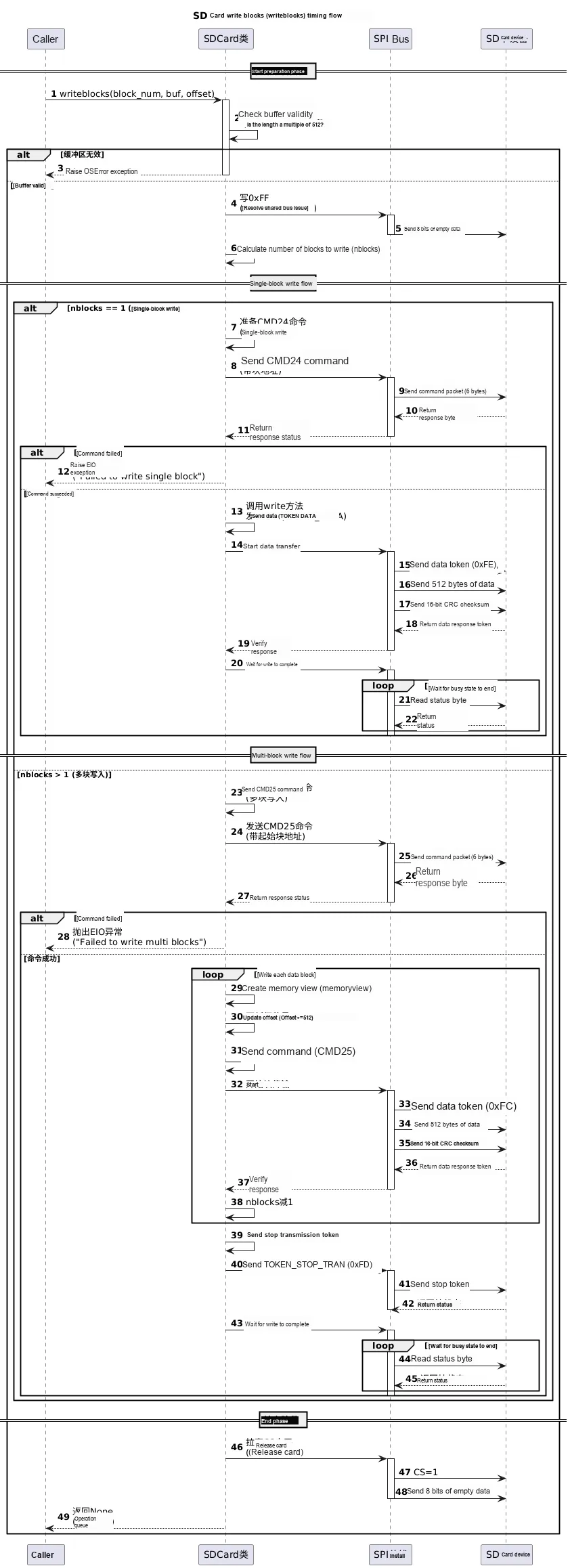
- Control operation
ioctlmethod: implements device control operations, including functions such as initialization, shutdown, synchronization, obtaining the number of blocks and block size, and erasing specified blocks; each operation is identified by an operation codeop, the corresponding operation is executed and the result is returned.
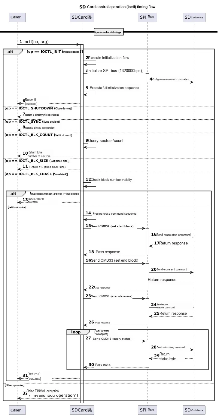
3.4.3.3 Application Experiment
The following code can be found in the elegance-devkit v1\Demo\73 FileSys_SDCard folder in the resource package we provided.
In the main program, the code is as follows:
# Python env   : MicroPython v1.23.0
# -*- coding: utf-8 -*-
# @Time    : 2024/9/30 PM 12:13
# @Author  : Li Qingshui
# @File    : main.py
# @Description : File system class experiment: mount a file system on the SD card and read and write

# ======================================== Import Modules ========================================

# Import hardware-related modules
from machine import SPI, Pin
# Import time-related modules
import time
# Import the custom SD card block device class
from sd_block_dev import SDCARDBlockDevice
# Import the custom SD card read/write class
from sdcard import SDCard
# Import the virtual file class
import vfs
# Import the file system operation class
import os

# ======================================== Global Variables ============================================

# Define embedded knowledge learning websites and their URLs
websites = [
    ("Embedded.com", "https://www.embedded.com"),
    ("Microchip", "https://www.microchip.com"),
    ("ARM Developer", "https://developer.arm.com"),
    ("SparkFun", "https://www.sparkfun.com"),
    ("Adafruit", "https://www.adafruit.com"),
    ("Embedded Systems Academy", "https://www.esacademy.com"),
    ("Electronics Hub", "https://www.electronicshub.org"),
]

# Define the CSV file path
csv_file_path = '/sdcard/embedded_websites.csv'

# ======================================== Functions ============================================

# ======================================== Custom Classes ============================================

# ======================================== Initialization ==========================================

# Power-on delay of 3 s
time.sleep(3)
# Print debug message
print("FreakStudio: Mount the SD Card to the file system")

# Initialize the SPI class, set the baud rate, polarity, phase, clock pin, and data pin
spi = SPI(1, baudrate=1320000, polarity=0, phase=0, sck=Pin(10), mosi=Pin(11), miso=Pin(12))
# Initialize the SD card class, using GPIO9 as the chip select pin
sdcard = SDCard(spi, cs=Pin(13))

# Create a block device using the SD card, with a block size of 512 bytes
block_device = SDCARDBlockDevice(sdcard = sdcard)
# Create a FAT file system on the block device
vfs.VfsFat.mkfs(block_device)
# Mount the block device to the /sdcard directory of the virtual file system
vfs.mount(block_device, '/sdcard')
# Print the current directory
print("Current Directory : ",os.listdir())

# ========================================  Main Program  ============================================

# Write the CSV file
with open(csv_file_path, 'w') as f:
    # Write the header
    f.write("Website Name,URL\n")
    for name, url in websites:
        # Write each row
        f.write(f"{name},{url}\n")

# Print the file location
print(f"CSV file written to SD card as '{csv_file_path}'.")
In the main program, we perform the following operations in sequence: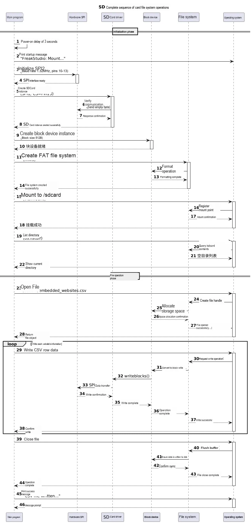
- Create
an SPIinstance, and configure the baud rate, polarity, phase and each pin (SCK,MOSI,MISO); createan SDCardinstance, and use the specifiedSPIinterface andGPIOas the chip select pin. - Use
SDCARDBlockDeviceto encapsulate the SD card as a block device with a block size of 512 bytes. - Use
vfs.VfsFat.mkfs (block_device)to format the block device and create a FAT file system. - Use
vfs.mount (block_device, '/sdcard')to mount the block device to the/sdcarddirectory of the virtual file system. - Use
with open (csv_file_path, 'w') as f:to open the CSV file at the specified path in write mode, first write the header"Website Name, URL\n", then iterate through the website information using a loop, and write the name and URL of each website line by line. - Finally, print a confirmation message indicating that the CSV file has been successfully written to the SD card, and provide the file path.
Burn the code, open the terminal, and the output is as follows:
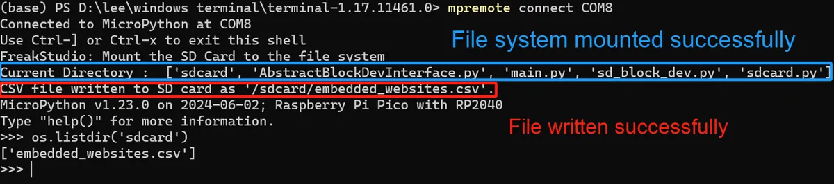
As you can see, the CSV file has been successfully written to the /sdcard directory. To view its content, we need to remove the SD card and connect it to a computer via a card reader. Note that you should unmount the file system first at this point:
os.umount('/sdcard')The unmount operation will forcibly flush all cached data to the SD card to ensure consistency between the physical storage and the actual data.
Meanwhile, note that you need to turn on the write-protect switch on the SD card to prevent the file system structure of the SD card from being altered after it is inserted into a computer, such as updates to the File Allocation Table (FAT), creation of hidden files (e. g. system files), or changes to file attributes.
After inserting the card reader into the computer, you will find a USB flash drive appears, which contains the CSV file we just wrote via the Raspberry Pi Pico:

Open the CSV file, and you can see that the Raspberry Pi Pico has successfully written the embedded learning website and its corresponding URL:
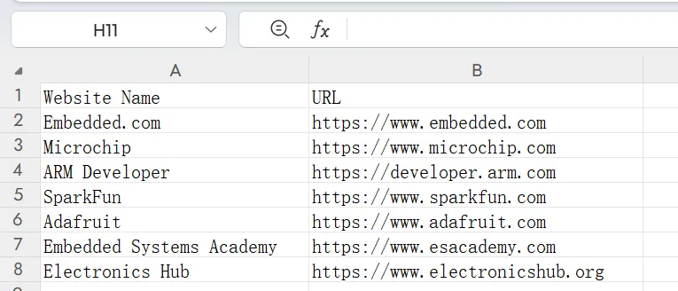
When you remove the SD card from the card reader and reinsert it into the SD card slot on the SD card module, you need to remount the file system:
vfs.mount(block_device, '/sdcard')We can enter the following code in the REPL to verify whether the remount is successful and the files are kept intact:
# Read the CSV file and print its content
with open(csv_file_path, 'r') as f:
    for line in f:
        # Remove the trailing newline and split the fields
        parts = line.strip().split(',')
        if len(parts) == 2:
            print(f"Website: {parts[0]:<30} URL: {parts[1]}")
        else:
            # Print the header or other rows
            print(line.strip())
The terminal output is as follows, showing that the previously saved CSV file has been successfully read:
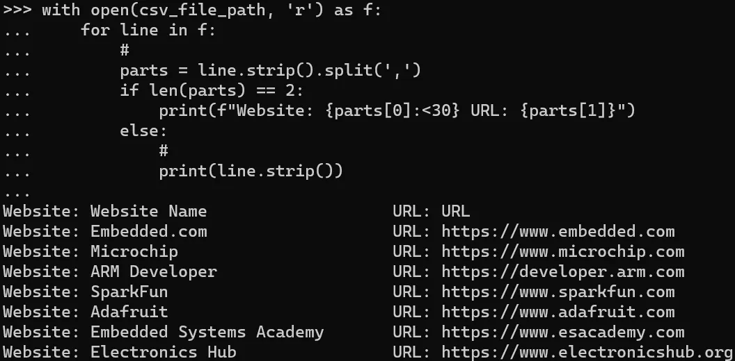
3.4 Application Experiment.mp4 16.0 MB
3.5 External EEPROM Mounted File System
3.5.1 Preparations before the experiment
We need to insert Fengya No. 1 Board - Environment and Storage Acquisition Board into Fengya No. 1 Board - Universal Compatible Expansion Board, and meanwhile turn on the SCL and SDA options of the SWITCH1 DIP switch on Fengya No. 1 Board - Environment and Storage Acquisition Board:
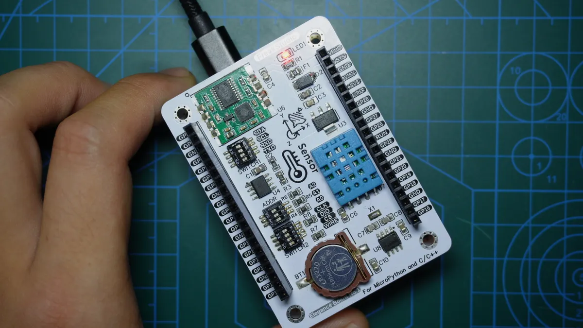
You can set its address by adjusting the Fengya No. 1 Board - Environment and Storage Acquisition Board via the ADDR DIP switches:
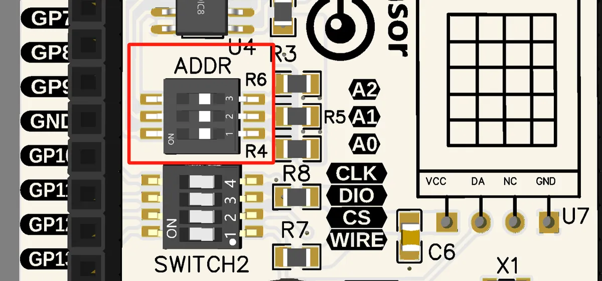
By default, the A2, A1 and A0 pins of the external EEPROM chip AT24C256 we use are all connected to GND (internal pull-down):
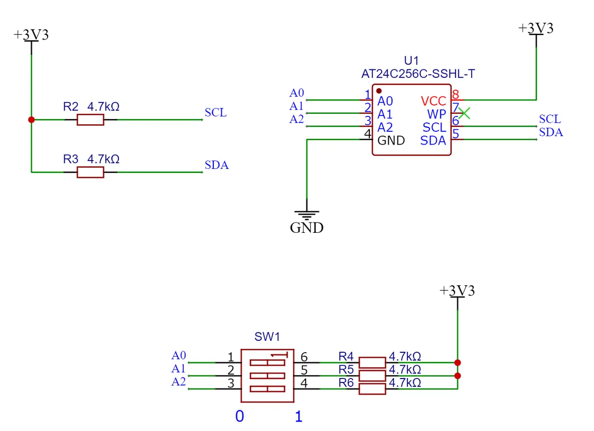
The device address is calculated as follows:
The connection between Raspberry Pi Pico and the external EEPROM module (AT24C256 chip) is shown in the following table:
device | Module Signals / Pins | Pico Pin (GPIO) |
AT24C256 chip | SDA | GP2 |
AT24C256 chip | SCL | GP3 |
Meanwhile, the AT24CXX class that we defined ourselves when explaining the I2C protocol will also be placed in a separate Python file at24cxx.py, the sample code is as follows:
# Python env   : MicroPython v1.23.0
# -*- coding: utf-8 -*-
# @Time    : 2024/9/27 PM 10:42
# @Author  : Li Qingshui
# @File    : at24cxx.py
# @Description : Implements an AT24CXX class for operating AT24CXX series EEPROMs

# ======================================== Import Modules =========================================

# Hardware-related modules
from machine import I2C, Pin
# Time-related modules
import time

# ======================================== Global Variables ============================================

# ======================================== Functions ============================================

# ======================================== Custom Classes ============================================

class AT24CXX:
    """
    AT24CXX class, used to operate AT24CXX series EEPROM chips over the I2C bus, supporting EEPROMs of multiple capacities.

    This class encapsulates I2C communication with the AT24CXX EEPROM and provides functions such as byte and page writing, reading, and erasing data.
    Supports EEPROM chips of different capacities (from 32KiB to 64KiB), reading and writing data over I2C.

    Attributes:
        i2c (I2C): I2C instance used to communicate with the AT24CXX chip.
        chip_size (int): Size of the EEPROM chip, default 64KiB.
        addr (int): I2C device address, default value is 0x50.
        max_address (int): Maximum accessible address of the device, depending on the size of the EEPROM.

    Methods:
        __init__(self, i2c, chip_size=AT24C512, addr=0x50):
            Initialize an AT24CXX class instance.

        write_byte(self, address: int, data: int) -> None:
            Write one byte to the specified address.

        read_byte(self, address: int) -> int:
            Read one byte from the specified address.

        write_page(self, address: int, data: bytes) -> None:
            Write one page of data to the specified address.

        read_sequence(self, start_address: int, length: int) -> bytes:
            Read data of the specified length sequentially.
    """

    # Different capacities of the AT24CXX series EEPROM
    AT24C32 = 4096      # 4KiB
    AT24C64 = 8192      # 8KiB
    AT24C128 = 16384    # 16KiB
    AT24C256 = 32768    # 32KiB
    AT24C512 = 65536    # 64KiB

    def __init__(self, i2c, chip_size: int = AT24C512, addr: int = 0x50) -> None:
        """
        Initialize an AT24CXX class instance.

        Args:
            i2c (I2C): I2C instance used to communicate with the AT24CXX chip.
            chip_size (int): Size of the EEPROM chip, default is AT24C512.
            addr (int): I2C device address, default is 0x50.

        Raises:
            ValueError: If the provided chip_size is not within the supported range.
        """
        # Check whether the EEPROM chip capacity is within the range defined by the AT24CXX class
        if chip_size not in [AT24CXX.AT24C32, AT24CXX.AT24C64, AT24CXX.AT24C128,
                             AT24CXX.AT24C256, AT24CXX.AT24C512]:
            raise ValueError("chip_size is not in the range of AT24CXX")

        self.i2c = i2c
        self.chip_size = chip_size
        self.addr = addr
        # Maximum address of the chip that the user can access
        self.max_address = chip_size - 1

    def write_byte(self, address: int, data: int) -> None:
        """
        Write one byte to the specified address.

        Args:
            address (int): Address to write to.
            data (int): Data to write, range 0-255.

        Raises:
            ValueError: If the address or data is out of the valid range.
        """
        # Check whether the address is within the valid range
        if address < 0 or address > self.max_address:
            raise ValueError('address is out of range')

        # Check whether the data is within the valid range
        if data < 0 or data > 255:
            raise ValueError("data must be 0-255")

        # Starting from the user-specified memory address `address`, write bytes([data]) to the EEPROM at device address addr
        # The memory address is 16 bits, two bytes
        self.i2c.writeto_mem(self.addr, address, bytes([data]), addrsize=16)
        # Delay 5 ms to wait for the EEPROM write to complete
        time.sleep_ms(5)

    def read_byte(self, address: int) -> int:
        """
        Read one byte from the specified address.

        Args:
            address (int): Address to read from.

        Returns:
            int: The data read.

        Raises:
            ValueError: If the address is out of the valid range.
        """
        # Check whether the address is within the valid range
        if address < 0 or address > self.max_address:
            raise ValueError("address is out of range")

        # Read one byte from the specified address
        value_read = self.i2c.readfrom_mem(self.addr, address, 1, addrsize=16)
        # Convert to an integer and return, using big-endian conversion
        return int.from_bytes(value_read, "big")

    def write_page(self, address: int, data: bytes) -> None:
        """
        Write one page of data to the specified address, handling page-crossing cases.

        Args:
            address (int): Starting address to write to.
            data (bytes): Data to write, with no limit on maximum length.

        Raises:
            ValueError: If the address, data length, or data is out of the valid range.
        """
        # Check whether the address is within the valid range
        if address < 0 or address > self.max_address:
            raise ValueError("address is out of range")

        # Check whether any data in the list is out of range
        for i in data:
            if i < 0 or i > 255:
                raise ValueError("data must be 0-255")

        # Check whether the length of data, combined with the starting address, is out of range
        if address + len(data) > self.max_address:
            raise ValueError("data exceeds maximum limit")

        # Get the boundary of the starting page
        page_boundary = (address // 64 + 1) * 64

        # Write the data in segments
        while data:
            # Calculate the number of bytes to write this time
            write_length = min(len(data), page_boundary - address)

            # Write one page of data to the specified address
            self.i2c.writeto_mem(self.addr, address, data[:write_length], addrsize=16)
            # Delay after writing to ensure completion
            time.sleep_ms(5)

            # Update the address and data
            address += write_length
            data = data[write_length:]

            # Update the page boundary
            page_boundary = (address // 64 + 1) * 64

            # If the current address exceeds the maximum address, stop writing
            if address > self.max_address:
                raise ValueError("address exceeds maximum limit")

    def read_sequence(self, start_address: int, length: int) -> bytes:
        """
        Read data of the specified length sequentially; the AT24CXX can read across pages and is not limited by page boundaries.

        Args:
            start_address (int): Starting address to read from.
            length (int): Number of bytes to read.

        Returns:
            bytes: The data read.

        Raises:
            ValueError: If the starting address and length are out of the valid range.
        """
        # Check whether the starting address and length are within the valid range
        if start_address < 0 or (start_address + length) > self.max_address:
            raise ValueError("address is out of range")

        # Read data of the specified length from the specified starting address
        return self.i2c.readfrom_mem(self.addr, start_address, length, addrsize=16)

# ======================================== Initialization ==========================================

# ========================================  Main Program  ===========================================
3.5.2 Implementation of EEPROM Block Device Class
Here, we first define a EEPROMBlockDevice class to manage EEPROM (e. g., AT24C256) as a block device, providing block read/write operations and device control functions. This class, like the RAM block device RAMBlockDev class, inherits from the abstract base class AbstractBlockDev and implements the functions of reading, writing, controlling, and erasing blocks.
The sample code is shown below:
# Python env   : MicroPython v1.23.0
# -*- coding: utf-8 -*-
# @Time    : 2024/9/27 PM 10:45
# @Author  : Li Qingshui
# @File    : eeprom_block_dev.py
# @Description : Defines an EEPROMBlockDevice class, including block read/write operations and device control functions

# ======================================== Import Modules =========================================

# Import the abstract base class of the virtual file block device
from AbstractBlockDevInterface import AbstractBlockDev
# Import the AT24CXX class
from at24cxx import AT24CXX

# ======================================== Global Variables ============================================

# Define error code constants, conforming to POSIX standard error codes
ENOERR = 0       # Operation successful
EPERM = 1        # Operation not permitted
EIO = 5          # I/O error
ENODEV = 19      # Invalid device/block number
EROFS = 30       # Read-only file system
EINVAL = 22      # Invalid argument
ENOSPC = 28      # No space

# ======================================== Functions ============================================

# ======================================== Custom Classes ============================================

# Custom EEPROM block device class, inherits from the abstract block device class
class EEPROMBlockDevice(AbstractBlockDev):
    """
    EEPROM block device implementation class, providing a block device interface that meets MicroPython file system requirements.

    This class implements the AbstractBlockDev abstract interface and supports emulating a block device through EEPROM memory,
    and can be used to mount MicroPython file systems (such as FAT, LittleFS, etc.).

    Attributes:
        eeprom (AT24CXX): AT24CXX series EEPROM driver instance
        block_size (int): Block size in bytes; must be an integer multiple of the EEPROM page size
        _is_initialized (bool): Device initialization state flag

    Methods:
        __init__(self, eeprom, block_size=512):
            Initialize the EEPROM block device instance
        readblocks(self, block_num, buf, offset=0):
            Read data from the specified block into a buffer
        writeblocks(self, block_num, buf, offset=0):
            Write data to the specified block or erase the block
        ioctl(self, op, arg):
            Device control operations
        _validate_block_num(self, block_num):
            Validate the block number (internal method)

    Note:
        - The block size must be an integer multiple of the EEPROM page size (usually a multiple of 8)
        - The block must be erased (0xFF) before a write operation
        - All methods are thread-safe
    """
    def __init__(self, eeprom: AT24CXX, block_size: int = 512) -> None:
        """
        Initialize the EEPROM block device instance.

        Args:
            eeprom (AT24CXX): AT24CXX series EEPROM driver instance
            block_size (int, optional): Block size (in bytes); must be aligned with the file system block size. Defaults to 512,
                                        and must also be an integer multiple of the EEPROM page size.

        Returns:
            None

        Raises:
            ValueError (EINVAL): If the block size does not meet the requirements
            OSError (ENODEV): If the EEPROM device is invalid
        """
        # Check whether the EEPROM page size is an integer multiple of the block size
        # The page size of AT24CXX series EEPROMs is an integer multiple of 8 bytes, so the block size must be an integer multiple of 8
        if block_size % 8 != 0 or block_size < 8:
            raise ValueError(EINVAL, "Block size must be multiple of 8")

        # Check whether the passed-in eeprom is an AT24CXX series EEPROM
        if not isinstance(eeprom, AT24CXX):
            raise OSError(ENODEV, "Invalid EEPROM device")

        # Parent class initialization function
        super().__init__()
        # Save the EEPROM instance
        self.eeprom = eeprom
        # Set the block size
        self.block_size = block_size
        # Initialize the device state to not enabled
        self.device_open = False

    def readblocks(self, block_num: int, buf: bytearray, offset: int = 0) -> None:
        """
        Read data from the specified block into a buffer.

        Args:
            block_num (int): Starting block number (starting from 0).
            buf (bytearray): Destination buffer; its length must be <= the block size.
            offset (int, optional): Offset within the block (not yet implemented). Defaults to 0.

        Returns:
            None

        Raises:
            ValueError (EINVAL): If offset≠0 or the buf length is invalid
            OSError (EIO): If the read fails
            OSError (ENODEV): If the block number is invalid
        """
        # Check whether the offset is 0
        if offset != 0:
            raise ValueError(EINVAL, "Offset must be 0")

        # Check whether the buffer length exceeds the block size
        if len(buf) > self.block_size:
            raise ValueError(EINVAL, "Buffer length exceeds block size")

        # Check whether the block number is valid
        if block_num < 0 or block_num >= self.ioctl(4, 0):
            raise OSError(ENODEV, "Invalid block number")

        # Read data
        try:
            # Calculate the starting address for writing
            addr = block_num * self.block_size
            # Write the data that was read into the buffer
            buf[:] = self.eeprom.read_sequence(addr, len(buf))
        except Exception as e:
            # Print the error message
            raise OSError(EIO, "Read failed") from e

    def writeblocks(self, block_num: int, buf: bytearray | None, offset: int = 0) -> None:
        """
        Write data to the specified block or erase the block.

        Args:
            block_num (int): Target block number (starting from 0).
            buf (bytearray | None): Data to write (None means erase the block).
            offset (int, optional): Offset within the block (not yet implemented). Defaults to 0.

        Returns:
            None

        Raises:
            ValueError (EINVAL): If the parameters are invalid
            OSError (EIO): Write failed
            OSError (ENOSPC): Block number out of range
        """
        # Check whether the offset is 0
        if offset != 0:
            raise ValueError(EINVAL, "Offset must be 0")

        # Calculate the length of data to write
        length = len(buf)
        # Check the data read length
        if length > self.block_size:
            raise ValueError(EINVAL, "Buffer too large")

        # Check whether the block number is valid
        if block_num < 0 or block_num >= self.ioctl(4, 0):
            raise OSError(ENOSPC, "Block number out of range")

        # Try to write the data
        try:
            # Calculate the starting address for writing
            addr = block_num * self.block_size
            # If buf is None, erase the block
            if buf is None:
                self.eeprom.write_page(addr, bytearray([0xFF]*self.block_size))
            else:
                # Write data
                self.eeprom.write_page(addr, buf)
        except Exception as e:
            raise OSError(EIO, "Write failed") from e

    def ioctl(self, op: int, arg: int) -> int | None:
        """
        Device control operation.

        Args:
            op (int): Operation code (use AbstractBlockDev constants):
                - IOCTL_INIT (1): Initialize the device
                - IOCTL_SHUTDOWN (2): Shut down the device
                - IOCTL_SYNC (3): Synchronize data
                - IOCTL_BLK_COUNT (4): Get the total number of blocks
                - IOCTL_BLK_SIZE (5): Get the block size
                - IOCTL_BLK_ERASE (6): Erase the specified block
            arg (int): Operation argument (depends on op):
                - IOCTL_BLK_ERASE: Block number to erase
                - Can be ignored for other operations

        Returns:
            int | None:
                - IOCTL_BLK_COUNT: Returns the total number of blocks
                - IOCTL_BLK_SIZE: Returns the block size
                - Other successful operations return 0
                - Unsupported op returns None

        Raises:
            ValueError: If the block number to erase is invalid
            NotImplementedError: If the operation code is not supported
        """
        # Initialize the device
        if op == AbstractBlockDev.IOCTL_INIT:
            # Set the device state to enabled
            self.device_open = True
            # Return success
            return ENOERR
        # Shut down the device
        elif op == AbstractBlockDev.IOCTL_SHUTDOWN:
            # Set the device state to disabled
            self.device_open = False
            # Return success
            return ENOERR
        # Synchronize the device
        elif op == AbstractBlockDev.IOCTL_SYNC:
            # Perform the synchronization operation (if needed)
            # Return success
            return ENOERR
        # Get the number of blocks
        elif op == AbstractBlockDev.IOCTL_BLK_COUNT:
            # Calculate and return the number of blocks
            return self.eeprom.chip_size // self.block_size
        # Get the block size
        elif op == AbstractBlockDev.IOCTL_BLK_SIZE:
            # Return the block size
            return self.block_size
        # Erase the specified block
        elif op == AbstractBlockDev.IOCTL_BLK_ERASE:
            # Get the block number to erase
            block_num = arg

            # Check whether the block number is valid
            if block_num < 0 or block_num >= self.eeprom.chip_size // self.block_size:
                raise ValueError(EINVAL, "Invalid block number")
            # Erase the specified block
            self.writeblocks(arg, None)
            # Return success
            return ENOERR
        else:
            # Unsupported operation code
            raise NotImplementedError("Unsupported ioctl operation")

# ======================================== Initialization ==========================================

# ========================================  Main Program  ===========================================
Here, the EEPROMBlockDevice class has the following methods:
__init__method: This method first checks whetherblock_sizemeets the page size requirement of theAT24CXXEEPROM, that is, it must be an integer multiple of 8;Then verify that the passed-ineepromis an instance ofAT24CXXto ensure it is a valid EEPROM device. After confirmation, initialize the parent classAbstractBlockDev, meanwhile record theeepromdevice instance, setblock_size, and mark the device status as closed (device_open = False).
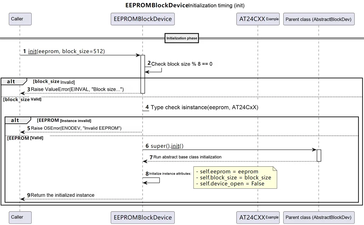
readblocksMethod: This method is used to read the data of the specified block into the buffer. First, calculate the start address of the block inEEPROM:addr = block_num * block_size, then callself.eeprom.read_sequence (addr, len (buf))to read data from the EEPROM, and write the read data intobuffor access by the upper-layer file system. Note here thatAT24CXXsupports cross-page reading and is not restricted by page boundaries.
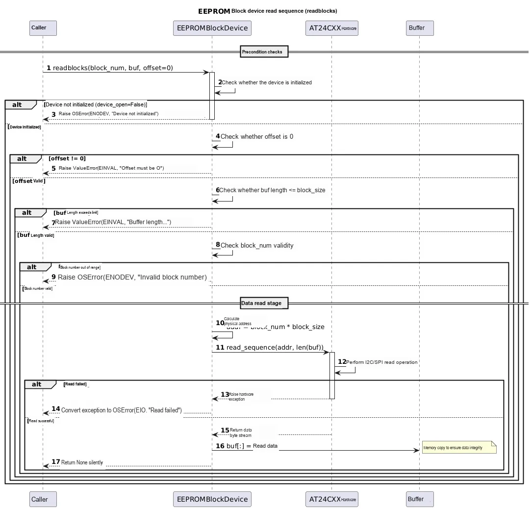
writeblocksMethod: This method is used to write data to a specified block or erase a block. First, calculate the start address of the block:addr = block_num * block_size. IfbufisNone, perform an erase operation (write all0xFF); otherwise, write the data inbufto the EEPROM. It should be noted that the cross-page writing issue has already been handled in the driver class for the EEPROMAT24CXX, so there is no need to worry about the need for page-based writing when the block size is larger than the EEPROM page size.
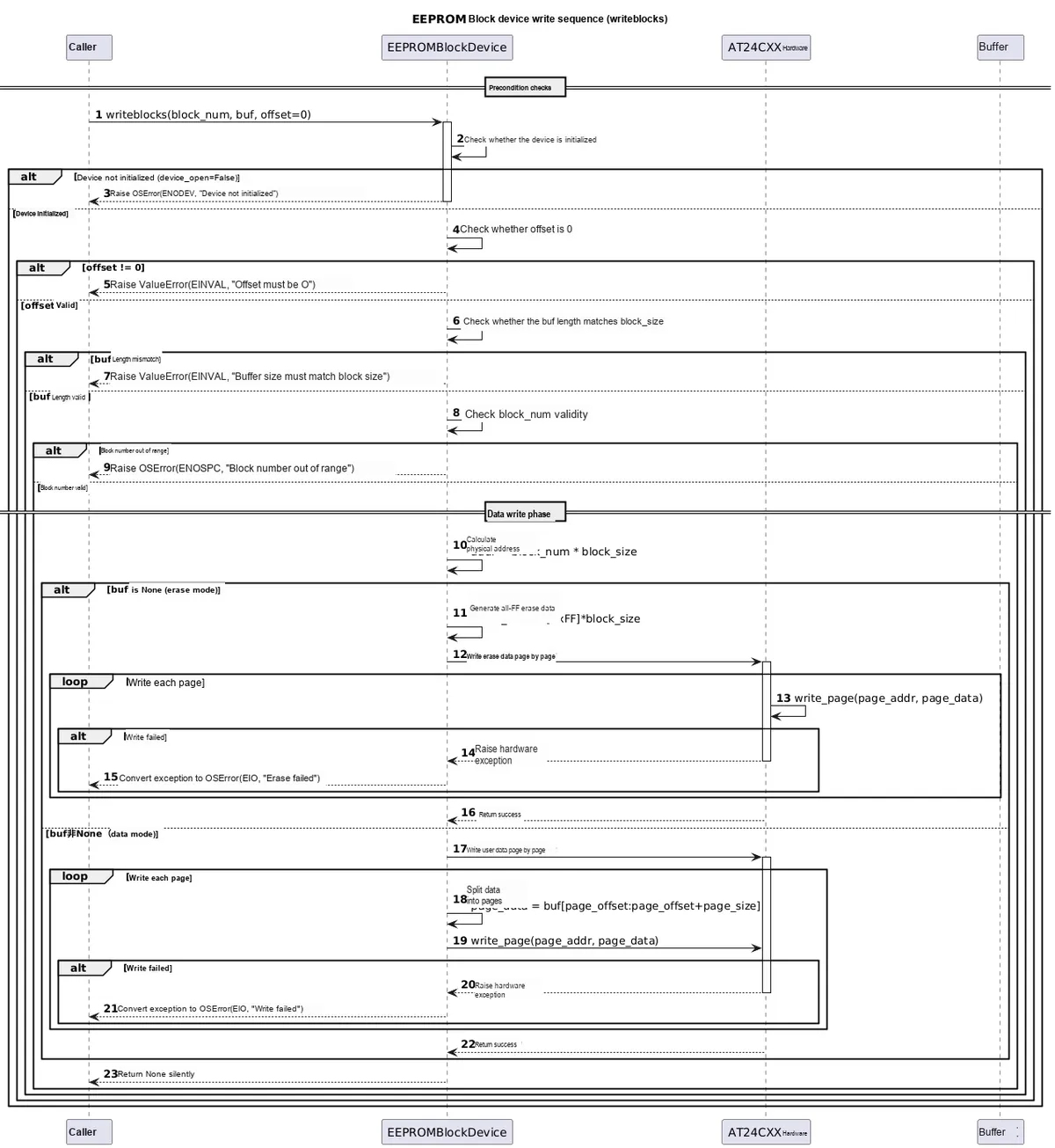
ioctlmethod: This method is used to execute control commands for block devices, such as initialization, synchronization, information acquisition, etc. These functions are similar to those of theRAMBlockDevclass. When erasing a specified block, it creates a buffer filled entirely with0xFFand writes it to the corresponding block.
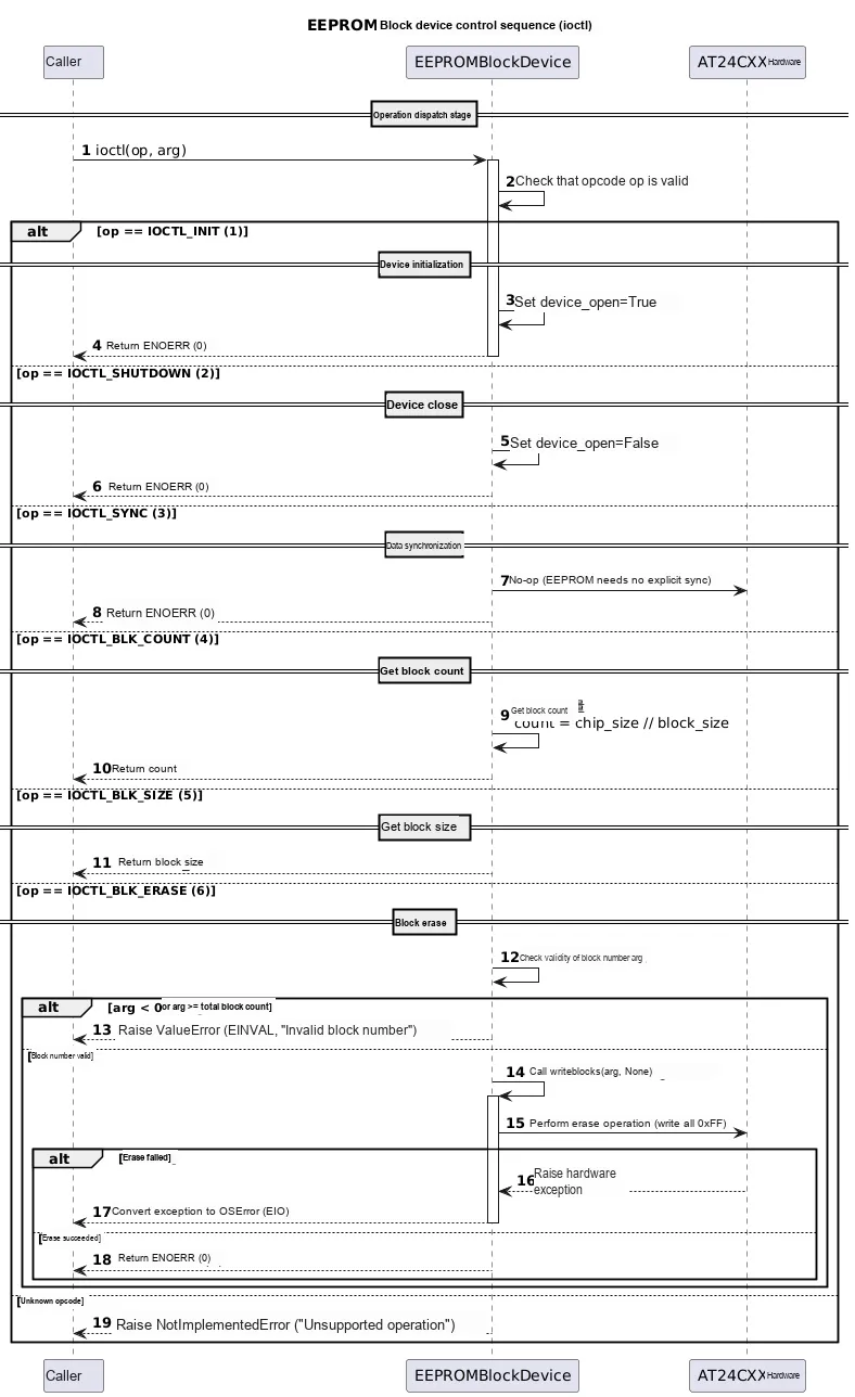
3.5.3 Application Experiment
The following code can be found in the elegance-devkit v1\Demo\74 FileSys_EEPROM folder within the resource package we provide.
In the main program, we create and mount a FAT file system on the AT24C256 EEPROM chip to store and read file data. Meanwhile, we test the data read/write function of the file system on the EEPROM chip, as well as the power-off data retention function of the EEPROM chip.
The sample code is as follows:
# Python env   : MicroPython v1.23.0
# -*- coding: utf-8 -*-
# @Time    : 2024/9/27 10:43 PM
# @Author  : Li Qingshui
# @File    : mian.py
# @Description : Used with the virtual file system class; mount a file system on an external EEPROM chip

# ======================================== Import Modules =========================================

# Hardware-related modules
from machine import I2C, Pin
# Time-related modules
import time
# Import the AT24CXX class
from at24cxx import AT24CXX
# Import the custom EEPROM block device class
from eeprom_block_dev import EEPROMBlockDevice
# Import the virtual file class
import vfs
# Import modules related to file operations
import os
# Import the JSON module
import json

# ======================================== Global Variables ============================================

# The AT24C256 chip address is 0x50, i.e. 0b1010000
# The upper 7 bits are the address bits and the lowest bit is the read/write control bit: 0 for write, 1 for read
AT24C256_ADDRESS = 0x50

# ======================================== Functions ============================================

# ======================================== Custom Classes ============================================

# ======================================== Initialization ==========================================

# Power-on delay of 3 s
time.sleep(3)
# Print debug message
print("FreakStudio: Mount the external EEPROM to the file system")

# Create a hardware I2C instance using the I2C0 peripheral, with a clock frequency of 400KHz, SDA pin 4, and SCL pin 5
i2c_at24c256 = I2C(id=0, sda=Pin(4), scl=Pin(5), freq=400000)

# Create an AT24C256 instance
at24c256 = AT24CXX(i2c_at24c256, AT24CXX.AT24C256, AT24C256_ADDRESS)

# Create the block device using the external EEPROM chip, with a block size of 512 bytes and 64 blocks in total
block_device = EEPROMBlockDevice(eeprom=at24c256, block_size=512)

# Create a FAT file system on the block device
vfs.VfsFat.mkfs(block_device)
# Mount the block device to the /eeprom directory of the virtual file system
vfs.mount(block_device, '/eeprom')

# ========================================  Main Program  ===========================================

# Use the os module to list the current directory and print it
print("Directory contents :",os.listdir())

# Configuration data
config_data = {
    "micropython_version": "v1.23.0",
    "required_modules": ["machine", "time", "vfs", "os", "json"],
    "author": "leeqingshui",
    "company": "FreakStudio"
}
# Convert the configuration data to JSON format
json_data = json.dumps(config_data)

# Create the configuration file and write the data
with open('/eeprom/config.json', 'w') as file:
    # Write the JSON data
    file.write(json_data)
# Print debug information
print("Config file created.")

# Read the file
try:
    # Open the configuration file for reading
    with open('/eeprom/config.json', 'r') as file:
        # Read the file contents
        content = file.read()
        # Print the file contents
        print("Config file content:")
        print(content)
# Catch file operation exceptions
except OSError as e:
    # Print the error message
    print("Error reading file:", e)

# Monitor the EEPROM power state; here we will unplug the EEPROM power
# and then reconnect it later to test whether data is retained after power loss
print("Monitoring EEPROM power...")

# Infinite loop to determine whether the EEPROM has lost power
while True:
    try:
        # Try to scan I2C devices
        devices = i2c_at24c256.scan()
        # Check whether the EEPROM address is in the device address list
        if AT24C256_ADDRESS in devices:
            print("EEPROM is powered on.Waiting...")
        else:
            # If it is not in the device address list, the EEPROM has lost power
            print("EEPROM is powered off.")
            # Exit the loop
            break
        # Wait 1 second before checking again
        time.sleep(1)
    # Catch the exception
    except Exception as e:
        # Print the scan error message
        print("Error scanning I2C devices:", e)
        # Wait 1 second before trying again
        time.sleep(1)

# Infinite loop to read the EEPROM data after power-up
while True:
    # Scan I2C devices
    devices = i2c_at24c256.scan()

    # Check whether the EEPROM address is in the device address list
    if AT24C256_ADDRESS in devices:
        # Print the message that the EEPROM has been powered up again
        print("EEPROM is powered on.")
        # Read the configuration file
        try:
            # Open the configuration file for reading
            with open('/eeprom/config.json', 'r') as file:
                # Read the file contents
                content = file.read()
                # Print the file contents
                print("Config file content after power restoration:")
                print(content)
        # Catch file operation exceptions
        except OSError as e:
            print("Error reading file after power restoration:", e)
        # Exit the loop
        break
    # Wait 1 second before continuing to scan
    time.sleep(1)
Here, we have carried out the following work: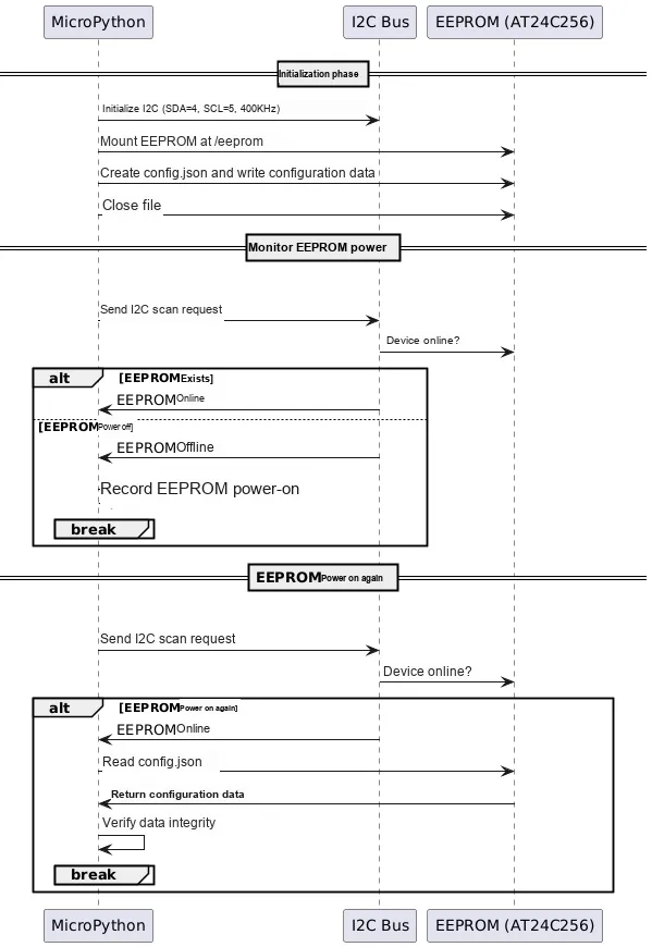
- Use the defined
AT24C256instance to create a block device, and set the block size to 512 bytes. - Format the block device as a FAT file system and mount it to the
/eepromdirectory of the virtual file system. - Define a piece of configuration data via a dictionary, convert it to JSON format, and then write it to the
/eeprom/config.jsonfile. - Open the configuration file, read it, and print the file content.
- Enter an infinite loop to continuously check the power status of the EEPROM, and exit the loop if the EEPROM loses power.
- Enter another infinite loop to continuously scan for I2C devices. If it is detected that the EEPROM has been powered back on, attempt to open the configuration file, read its content, and then terminate the program.
Burn the code, open the terminal, and the following content will be displayed:
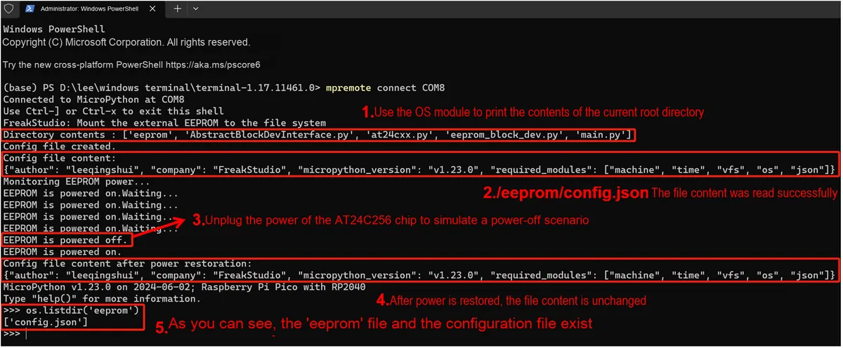
When the terminal outputs in a loop EEPROM is powered on.Waiting.. ., we can unplug the Fengya No. 1 Board - Environment and Storage Acquisition Board to power it off; after waiting for a while, plug in the Fengya No. 1 Board - Environment and Storage Acquisition Board again to power it on.
It can be seen that the EEPROM chip can normally implement the data read/write function of the file system and the power-off data retention function.
3.5 Application Experiment.mp4 13.7 MB
We can use the following command to test whether the erase function works properly:
os.remove('eeprom/config.json')The above command has deleted the config.json file. Then enter the following command to view the files in the eeprom folder:
os.listdir('eeprom')It can be seen that the file has been deleted at this point:

References
- MicroPython Language and Implementation: Using the File System
https://docs.singtown.com/micropython/zh/latest/openmvcam/reference/filesystem.html
- Raspberry Pi Pico File System Application: Implementation of a Data Logger
https://pico.nxez.com/2023/10/23/data-logger.html
- Essentials of Microcontroller Use Learning about Peripherals: Programming Part 1
https://www.renesas.com/en/support/engineer-school/mcu-programming-peripherals-05
- Thorough and Detailed Explanation of EEPROM Working Principle
https://www.cnblogs.com/sunshine-jackie/p/8137377.html
- vfs – virtual filesystem control
https://docs.micropython.org/en/latest/library/vfs.html#vfs.AbstractBlockDev
- SD Specifications SDUC Host Implementation Guideline Version 1.00
- SD Card Specification SD3.0 UHS-I
- SD Specifications Part 1 Physical Layer Simplified Specification Version 6.00
- Basic Knowledge and Purchasing Guide for SD Cards
https://www.cnblogs.com/Javaer1995/p/18331745
- Circuit Structure and Working Principle of Micro SD Card
https://www.sd-nand.com/news/technology/277.html
- Schematic Diagram of the Internal Structure of SD Card for STM32
https://www.eeworld.com.cn/mcu/eic666379.html
- Interface Between Raspberry Pi Pico and MicroSD Card Module and MicroPython Programming for Reading and Writing MicroSD Memory Cards
https://blog.csdn.net/yuanzywhu/article/details/131592815
- Getting Started Tutorial for SD Card SPI Mode
https://blog.csdn.net/weixin_37366441/article/details/120461015
- STM32 Development: Reading and Writing SD Cards via SPI Protocol and Introduction to SD Card SPI Timing
https://cloud.tencent.com/developer/article/2179371
Addendum: closure
A closure is an important concept in Python. It refers to a function defined inside another function, and this inner function can access the variables of the outer function even after the outer function's scope has terminated; simply put, a closure is a function that retains access to the variables in the outer scope where it was defined, even when those variables no longer exist in that outer scope. This feature allows us to create more flexible functions, such as returning functions with specific behaviors without explicitly passing all required parameters.
Three conditions for closure:
- There must be a nested function (i. e., a function defined inside another function)
- An inner function must reference the variables in the outer function
- An outer function returns an inner function instead of executing it immediately
In the following code, we implement a closure inner_function:
def outer_function(x):
    def inner_function(y):
        # inner_function can access the x variable of outer_function
        return x + y
    return inner_function
In this example:
outer_functionreturnsinner_functioninner_functionreferencesthe variablein outer_functionx, which is the key to closure- Even after
outer_functionfinishes executing, its variablexcan still be accessed byinner_function.
When using closures, we need to note that the execution of a closure can be divided into the following stages:
- Definition phase: When an outer function is invoked, the inner function (i. e., a closure) is defined and captures the variables within the outer function; at this point, the outer function returns the closure function, but the closure has not yet been executed
- Invocation Phase: The closure will only be executed when you explicitly call the returned closure function; when the closure is executed, it will use the captured external variables and perform operations or other actions as needed
For example, for the closure inner_function implemented above, using the following code will only call the outer function, not the closure:
# outer_function executes and returns the closure, which captured x=5, but the closure has not been executed yet
closure = outer_function(5)
When we call closure (3), the closure will execute, using the previously captured x= 5 and the currently passed-in y= 3 for calculation, and return the result:
# Now we can call the closure, passing in y=3, and the closure starts executing
result = closure(3)
# Outputs 8
print(result)
Using closure has the following advantages:
- Deferred execution logic: A closure allows you to defer the execution of certain logic until it is actually needed. For example, you can create a function with specific behavior without executing it immediately.
- Data hiding: A closure can store states or data inside a function, which cannot be directly accessed by external code, similar to an encapsulation mechanism
- Maintain state: Through closure, you can remember the variables of an outer function and use these variables in subsequent operations
- More concise code: closure makes function definition and behavior more flexible, reducing the need for explicit parameter passing
Version Record
Version Number | Modifier | Time | Content |
v1.2.0 | Li Zisheng | 2025/12/24 | Initialize the document, based on MicroPython version v1.23.0. |