
Contents
- 1. Hardware Explanation
- 1.1 Introduction to DMA
- 1.2 DMA on Raspberry Pi Pico
- 2. Software Control Method
- 2.1 Constructor Method of the rp2.DMA Class
- 2.2 Other Methods of the rp2.DMA Class
- 2.3 Attributes of the rp2.DMA Class
- 3. Application Examples
- 3.1 DMA Class Implements Memory-to-Memory Data Transfer
- 3.2 DMA Class Implements Memory-to-Peripheral Data Transfer
- 3.3 DMA Class Implementation for Peripheral-to-Memory Data Transfer
- 3.4 DMA implements chained triggering
- References
- Version History
1. Hardware Explanation
1.1 Introduction to DMA
1.1.1 Introduction to DMA (Direct Memory Access)
In traditional data transmission modes, the CPU of a microcontroller unit (MCU) is responsible for reading data from a peripheral (such as I2C, UART, ADC, etc.) and storing it in memory, or reading data from memory and writing it to the peripheral. This approach requires the CPU to continuously process read and write operations, which easily leads to excessive CPU load and affects the overall performance of the system.
The introduction of DMA changed this situation. DMA, short for Direct Memory Access, is a technology that allows hardware subsystems to exchange data directly with memory without the intervention of the CPU (Central Processing Unit). DMA significantly improves system performance, especially in applications that require large volumes of data transmission, such as audio/video processing, network communication, and Data Acquisition.
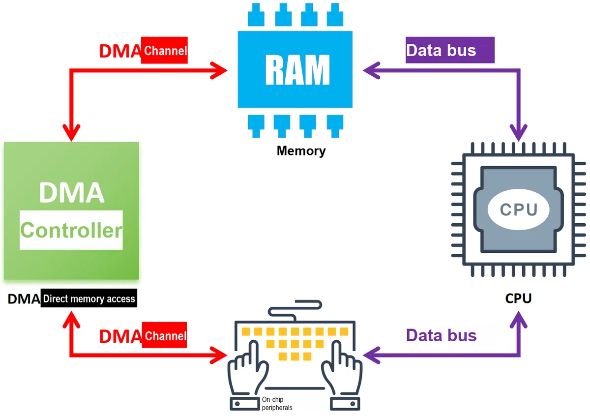
Using DMA for data transmission enables automatic data transfer in the background, so the CPU does not need to participate in the specific data handling work, which frees up more CPU resources for executing other tasks; meanwhile, since the DMA controller directly exchanges data with the memory and devices, it can transmit data at a faster speed than that controlled by the CPU.
Compared with the method where the CPU reads data in the interrupt callback function after a peripheral generates an interrupt, DMA transfer can significantly reduce the number of interrupts related to data transmission that the CPU has to process, thereby lowering the interrupt overhead of the system.
1.1.2 Working Principle of DMA
The DMA controller can directly communicate with the system bus and is responsible for managing data transmission between devices and memory. It operates through the following steps: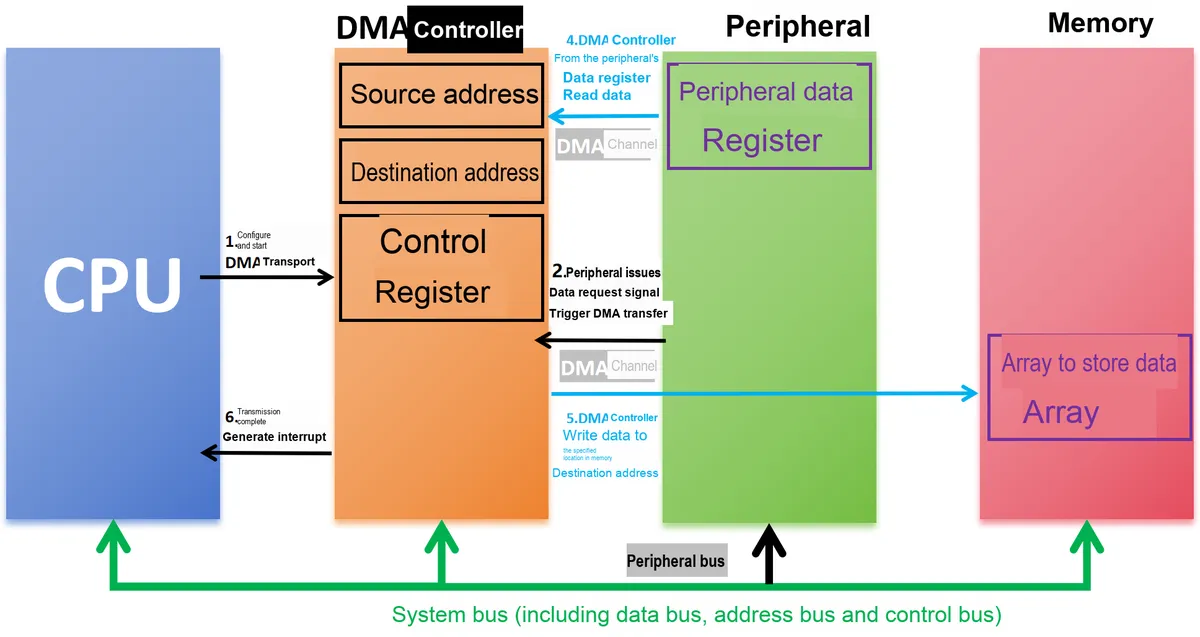
- DMA transfer request: Before using DMA, we first need to configure information such as the source address, destination address and data transfer size for DMA data transmission. When a peripheral (such as a UART or ADC) needs to perform data transmission, it sends a transfer request to the DMA controller. At this point, the CPU can configure and initiate the DMA transfer, but the actual data operation of the transfer is taken over by the DMA controller, which temporarily seizes control of the system bus;
- DMA transfer: The DMA controller directly accesses memory via the system bus to move data from a source address (e. g., a device) to a destination address (e. g., memory), or from memory to a device. This process does not require CPU intervention; the DMA controller can complete the transfer operation in the background, and data transmission is carried out through DMA channels;It should be noted that the DMA channels responsible for data transmission rely on the system bus;
- Interrupt Notification: When the DMA transfer is completed, the DMA controller will send an interrupt signal to the CPU to notify that the transfer has finished, and meanwhile hand over the system bus controller to the CPU. At this point, the CPU can continue to process data-related tasks without spending time and resources on data transfer.
It can be seen that the DMA controller and DMA channels enable devices to transmit data without overloading the CPU; without DMA channels, the CPU would use the system bus to send instructions and data to the peripheral bus, which then routes them to the target peripheral device, before copying each piece of data into the array designated for data storage within that target device. Using the peripheral bus for read/write operations would occupy the CPU, preventing it from performing any other tasks until the operation is completed.
Here, the CPU, DMA, and other peripherals all share the same system bus. If the CPU is using the bus to perform a memory access operation while the DMA also needs to transfer data to or read data from memory via the bus, a contention for the bus will arise between the two parties. In this case, there is an arbitration mechanism in the system to determine the right to use the bus and which party will take control of it; the arbiter will decide whether the CPU or the DMA should have priority in using the bus based on factors such as task priority, urgency, and system status.
However, there are also some issues encountered when using DMA for data transmission, for instance the cache coherence problem: when an MCU is equipped with a cache mechanism (such as the F7 series, U5 series and H7 series of STM32 microcontrollers), the CPU usually accesses the cache first instead of directly accessing the RAM memory to improve data access speed when reading or writing data; however, the DMA controller communicates directly with the RAM, bypassing the CPU cache.
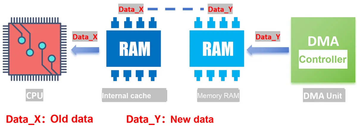
This will lead to the following issues:
- Stale Data: If the CPU reads a block of data from the cache and modifies it in the cache without synchronizing these modifications back to RAM in a timely manner, the RAM data read by the DMA controller will be stale: for example, when the CPU accesses location X in memory, the current value will be stored in the cache, and subsequent operations on X will update the cache copy of X but not the RAM version of X in memory; if the cache is not flushed to memory before the device next attempts to access X, the device will receive the stale value of X;
- Data inconsistency: Conversely, if the DMA controller writes data to the RAM while the CPU cache is not invalidated or updated in time, the data read by the CPU from the cache may be incorrect, leading to data inconsistency.
To avoid or solve the cache coherence problem in MCUs, the following methods can be used:
- Disable cache: In some cases, you can choose to disable the cache before using DMA to ensure that DMA operations are not affected by cache inconsistency. However, this may lead to performance degradation, as all memory accesses will require direct access to RAM after the cache is disabled;
- Cache Clean and Invalidate Operations :
- Cache Clean: Before a DMA operation, the CPU can be forced to write back the data in the cache to the RAM to ensure that the data in the RAM is consistent with that in the cache;
- Cache Invalidate: After a DMA operation, you can force the CPU to invalidate the cache, so that it will fetch data from the RAM again on the next access.
- Use non-cacheable memory regions: Some MCUs support marking certain memory regions as "Non-Cacheable". You can mark the memory regions used by DMA as non-cacheable to avoid cache coherence issues;
- Use dedicated DMA regions: Some MCUs may have memory regions specifically designated for DMA operations, which avoid conflicts with the CPU cache. When performing DMA operations, data transfer is only carried out within these dedicated regions.
1.1.3 Types of DMA
According to the direction and mode of data transmission, DMA can be divided into the following types: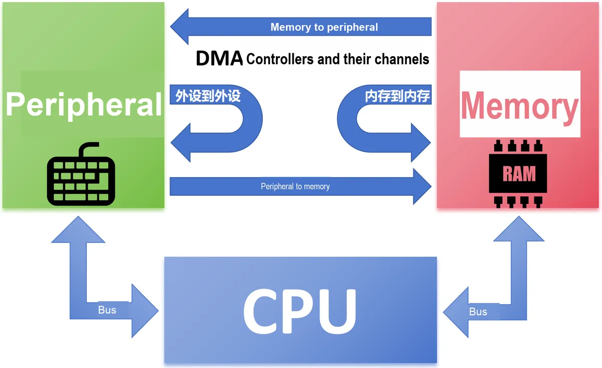
- Memory-to-Memory Transfer: In this transfer mode, the DMA controller copies data from one memory area to another, which is commonly used for fast duplication of large blocks of memory data, such as the rapid swapping of image/video frame buffers or the fast forwarding of network data packets between memory regions.
- Peripheral-to-Memory Transfer: The DMA controller directly writes data from the peripheral to the memory without CPU intervention. Examples include reading data from a storage device (such as an SD card or NAND Flash) to memory, directly acquiring sensor data from an ADC peripheral to memory, or reading data from a storage device (such as an SD card or NAND Flash) to memory.
- Memory-to-Peripheral Transfer: The DMA controller directly transfers data in the memory (such as a segment of audio data) to a peripheral device (such as an audio output device); for example, outputting audio/video data from the memory to peripherals like DACs and displays, or sending processed data from the memory to communication interfaces (UART, SPI, etc.) for transmission.
- Peripheral-to-Peripheral (P2P) transfer: It is commonly used for data copying between storage devices, data conversion and synchronization between peripherals, or accelerating encryption/decryption processing. Typical use cases include copying data from an SD card to NAND Flash, transferring data collected by an ADC to a DAC via DMA for analog output, and outputting dual-channel audio data from two peripherals simultaneously.
1.1.4 DMA Transfer Modes
DMA controllers typically support multiple transfer modes; the following are several common ones:
- Single Transfer Mode: In this mode, only one data unit (e. g., a byte or a word) is transferred per operation. The DMA controller releases the bus control right after each data transfer, so that the CPU or other devices can access the bus; it is applicable to scenarios with strict bus sharing requirements (such as when the CPU is processing tasks and peripherals are transferring small batches of data at the same time);
- Burst Transfer Mode: After the DMA controller obtains bus control, it continuously transmits a batch of data (such as a block of memory data). During this period, the DMA controller exclusively occupies the bus and does not release control until the transmission is completed; it is suitable for scenarios requiring high-speed data transmission (such as copying large files from a hard disk or high-speed image acquisition by a camera, where the pursuit of maximum transmission speed means temporary bus occupation will not affect core tasks);
- Circular Buffer Transfer Mode (Circular Buffer Mode): The DMA controller transfers data cyclically within a predefined buffer, which is suitable for applications with continuous data streams, such as Data Acquisition, where sensor data is continuously stored into the buffer;
- Auto-Request Mode: When the same data transmission needs to be repeated (for example, transferring sensor data to memory at regular intervals), the DMA controller will automatically send a request and perform the transmission, which is suitable for periodic data transmission scenarios (such as collecting temperature data every 100ms and sending serial port data every 50ms).
1.1.5 Structure of DMA
For the DMA unit of an MCU, it can generally be divided into the following parts: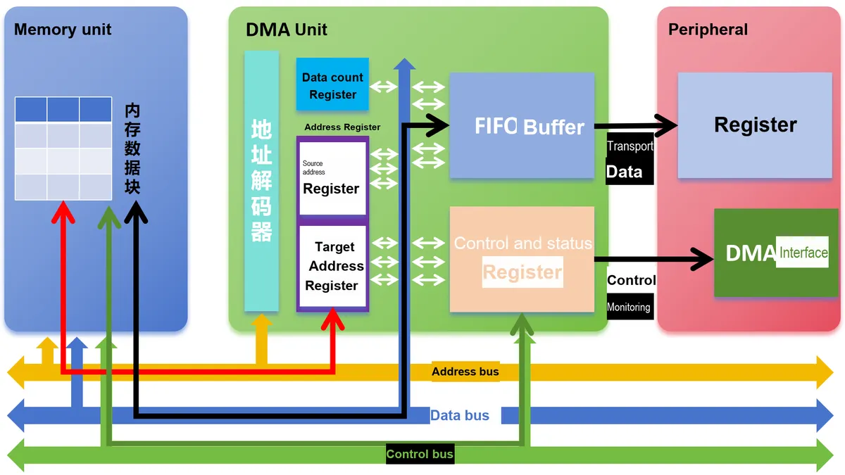
- DMA Channels: The DMA controller in an MCU usually supports multiple DMA channels, each of which can be independently configured for data transmission between different peripherals or memories. Meanwhile, each channel can process different data streams simultaneously and be assigned a different priority; when multiple channels request bus access at the same time, the channel with a higher priority will obtain the Right of access first;
- Address Registers
- Source Address Register (SAR): stores the source address of the data to be read, which can be either the register address of a peripheral or a memory address;
- Destination Address Register (DAR): stores the destination address to which data is to be written, and this destination address can also be a peripheral register address or a memory address;
- Address auto-increment/decrement function: In most microcontroller units (MCUs), the DMA controller can be configured to automatically increment or decrement the address pointer after each transfer, which facilitates the processing of consecutive data blocks.
- For example, after the data transfer starting from memory address 100 is completed, the system will automatically jump to address 101 and proceed sequentially; or it will jump backward from address 200 to address 199;
- It facilitates the processing of consecutive data blocks (such as transferring an entire file segment or a single video frame) without the need for repeated address configuration, thus improving transmission efficiency.
- Data Registers
- FIFO buffer: used to temporarily store data during DMA transfers, ensuring continuous data transmission while reducing latency between data requests and actual transfers;
- Data Counter Register (Data Counter, DCR): This register stores the amount of data (usually in bytes or words) transmitted by the current channel. When the data count decreases to 0, it indicates that this transmission is completed, and the DMA will stop the task or trigger a subsequent notification;
- Transfer Size Control: It allows configuration of the data width for transmission, such as 8-bit, 16-bit or 32-bit, to adapt to the data formats of different peripherals and memories, ensure "specification matching" of transmitted data, and avoid data misalignment or errors (for example, if a peripheral can only receive 8-bit data, transmission cannot be performed in 16-bit mode).
- Control Registers
- Channel Control Register (CCR): used to configure the operating mode of each DMA channel, including starting or stopping DMA transfers, setting priorities, selecting trigger events, etc. ;
- Interrupt Control: The DMA controller can be configured to generate an interrupt when a transfer completes, a transfer error occurs, or a specific transfer progress milestone is reached. Upon receiving the interrupt signal, the CPU will execute the corresponding interrupt handler — for example, notifying the software to read data after a transfer completes, or triggering retry or alarm logic when a transfer error occurs.
- Triggers
- Hardware trigger: Automatically triggered by a specific event of a peripheral. For example, when an ADC (Analog-to-Digital Converter) completes a voltage acquisition, a UART (Universal Asynchronous Receiver/Transmitter) finishes receiving a data, or a camera captures a frame of image, these peripherals will actively send a "trigger signal" to the DMA, and the DMA will automatically start the transmission upon receiving the signal;
- Software triggering: The software can also manually trigger DMA transfer by writing to the control register.
- DMA Arbiter
- Bus Arbitration: The DMA controller needs to share the MCU's system bus with the CPU and other bus masters (such as another DMA controller or a bus interface). The arbiter is responsible for managing the bus Right of access among DMA channels to ensure stable and efficient operation of the system;
- Round-robin and fixed priority: The arbiter can determine the bus access sequence based on the priority of channels, and common arbitration strategies include fixed priority and round-robin priority (i. e., polling).
1.2 DMA on Raspberry Pi Pico
1.2.1 Introduction to the DMA Unit on Raspberry Pi Pico
The DMA controller of the RP2040 features independent read and write master connections, which are respectively connected to the chip's bus architecture, enabling the DMA to perform parallel read and write operations. The specific architectural features are as follows: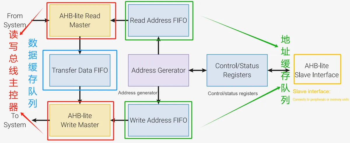
- Read and Write Master: The read master of DMA can read data from a certain address every clock cycle, while the write master can write data to another address. This means that DMA can simultaneously perform one read access and one write access within each clock cycle, with a maximum data transfer of 32 bits per operation.
- Address Generator: The address generator is responsible for generating matching read and write addresses, which are then supplied to the read-write master controller via an address FIFO. The FIFO plays a critical buffering role in the DMA architecture, ensuring smooth data transmission.
- Independent Channels: The DMA controller of the RP2040 supports 12 independent channels. These channels can independently manage a series of bus transfer tasks, allowing multiple transfer sequences to run simultaneously. Each channel is equipped with its own Control and Status Registers (CSRs) for software configuration and monitoring.
- Multi-channel concurrency: When multiple channels are active simultaneously, DMA adopts a round-robin scheduling policy to fairly allocate bandwidth among all channels requesting data transmission, ensuring balanced resource utilization across each channel.
- The DMA channels of the RP2040 support three types of transfers: memory-to-peripheral, peripheral-to-memory, and memory-to-memory.
Each DMA channel has its own control and status registers, through which software can configure the channel, including the following parameters:
- Transfer Direction: This configures the direction of data transfer, which can be memory-to-peripheral, peripheral-to-memory, or memory-to-memory transfer.
- Transmission Data Size: The size of the data to be transmitted can be 32-bit, 16-bit or 8-bit. The source data size and destination data size of each channel must be the same.
- Address Update: The DMA automatically updates the source address and destination address according to the configuration to ensure that data is transmitted from the source to the destination in sequence.
- Transmission Mode: DMA supports single transmission and loop transmission modes. In loop mode, the transmission can continue without reconfiguration.
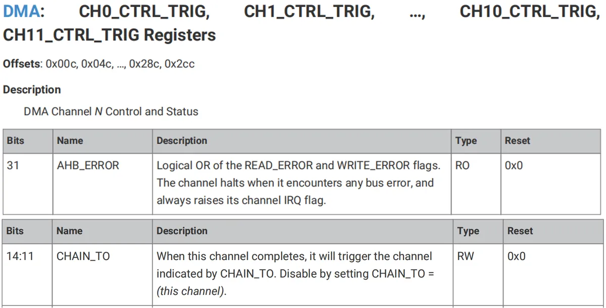
- Chaining Transmission (Chaining): A DMA channel can configure another channel to perform subsequent transmission tasks. Through the
CHAIN_TOoption, callback and cooperative operation between channels are realized, enabling the DMA controller to execute complex tasks more autonomously.
1.2.2 DMA Channel Configuration
Each DMA channel has four main Control and Status Registers (CSRs) for managing the data transfer process:
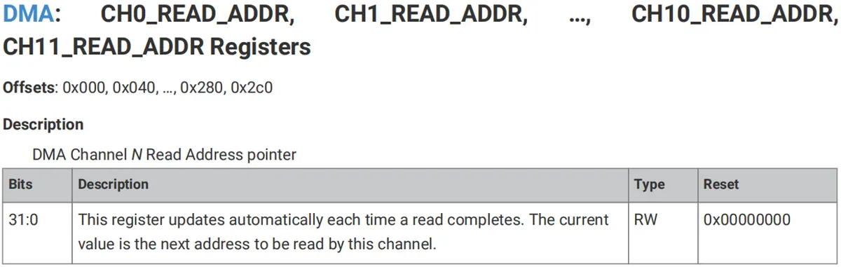
- READ_ADDR (Read Address Register): This is the address pointer for read operations; whenever a read operation is completed, the register will automatically update to the next address to be read.
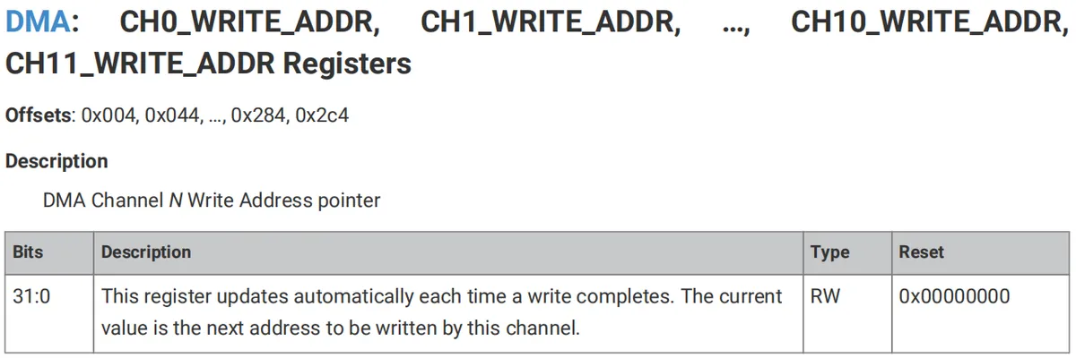
- WRITE_ADDR (Write Address Register): This is the address pointer for write operations; after each write operation is completed, this register will automatically update to the next address to be written.
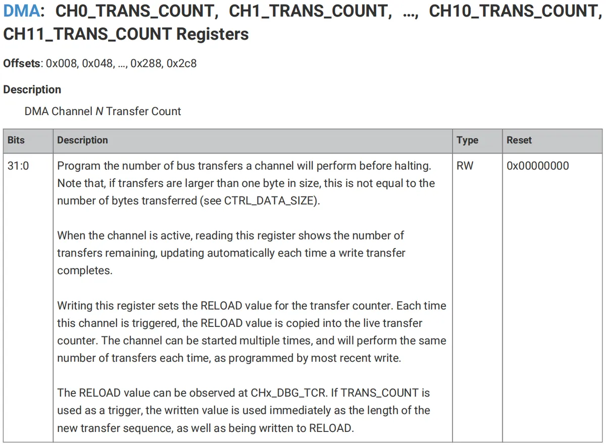
- TRANS_COUNT (Transfer Counter): This register is used to set the number of transfers that the DMA channel performs in a single transfer sequence (each transfer can be 1 byte, 2 bytes, or 4 bytes); when a transfer is in progress, reading this register returns the remaining number of transfers, and the value in the register is automatically updated as each write operation completes.
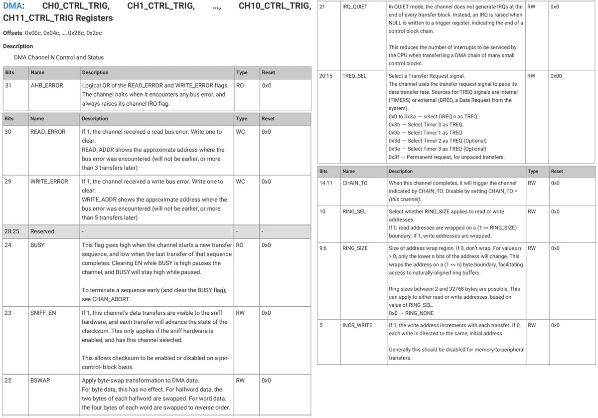
- CTRL (Control Trigger Register): This register governs the enablement, configuration and status monitoring of the DMA channel. Its primary control bits include EN (Enable Bit), BUSY (Busy Flag), TREQ_SEL (Transfer Request Select), CHAIN_TO (Chained Trigger), DATA_SIZE (Data Size), and RING_SIZE (Address Wrap), in addition to several error indication flag bits and priority setting data bits.
1.2.2.1 Read Address and Write Address Registers
READ_ADDR and WRITE_ADDR are registers used to store the memory address from which the DMA channel will read data or to which it will write data next time. These registers are automatically updated after each read or write operation, and will increment according to the transfer size setting configured in the CTRL register.
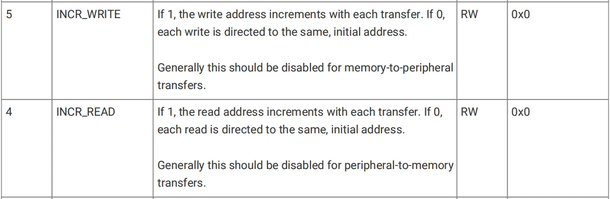
Specifically, the increment step size can be 1,2, or 4 bytes, depending on the configured transfer size. It should be noted that the READ_ADDR register and the WRITE_ADDR register must always be aligned to the current transfer size (the size specified in CTRL.DATA_SIZE): if the transfer size is byte (1 byte), halfword (2 bytes), or word (4 bytes), the corresponding address must be aligned to a 1-, 2-, or 4-byte boundary.

Typically, whenever a new transmission sequence commences, the software needs to reprogram these registers to set a new start address. However, there are also scenarios where address increment is not required:
- Scenarios where the address does not increment: If the address is that of a peripheral's FIFO (First-In, First-Out) buffer, and the next transfer sequence also needs to read data from or write data to this address, there is no need to reprogram the register, i. e., the original address value is retained
- Scenarios of Continuous Memory Transfer: When DMA is configured to transfer multiple consecutive data blocks from memory, the data of each block is usually stored at different memory addresses, but these blocks may be a predefined set of memory buffers. To process these data blocks efficiently, the address register of DMA will automatically increment to the start address of the next buffer after completing the transfer of each data block, without requiring manual intervention from software.
At this point, the DMA will use the current value as the starting address for the next transfer.
1.2.2.2 Transmission Count Register
TRANS_COUNT The register is responsible for managing the remaining number of transfers in the current transfer sequence, and determines the total number of transfers at the start of each transfer:
- Read TRANS_COUNT: During a transfer, reading the
TRANS_COUNTregister returns the number of remaining transfers in the current transfer sequence. This value automatically decrements as the transfer proceeds, indicating how many transfers are still left. - Write to TRANS_COUNT: The
TRANS_COUNTregister is used to set the number of transfers for the next transfer sequence. When a new transfer sequence is initiated, the value just written will be loaded into the transfer counter and start decrementing with each transfer; - Reload Mechanism of the Transmission Counter: Each time a new transmission sequence starts, the most recently written value of
TRANS_COUNTis copied into the active transmission counter, which decrements as the transmission proceeds until the transmission is completed; for debugging purposes, the most recently written value can be read fromDBG_TCR(i. e., theTRANS_COUNTreload value register).
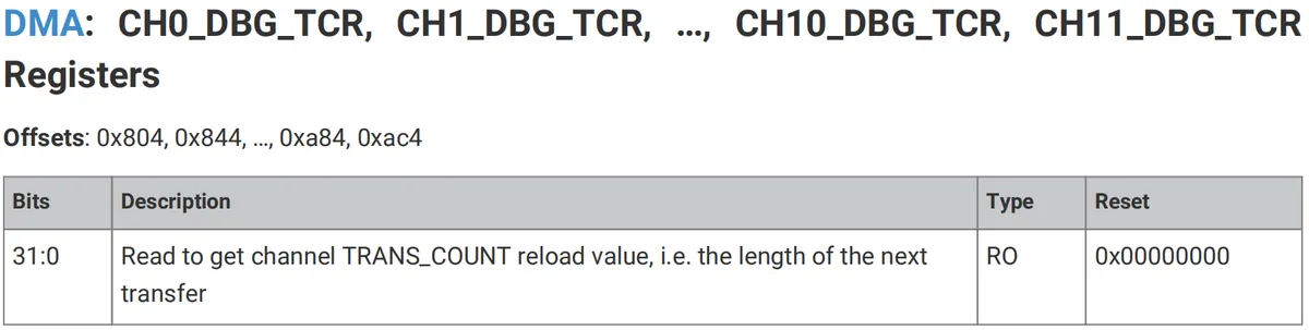
- Automatic retransmission count: If the DMA channel is not rewritten between multiple triggers,
TRANS_COUNTit will perform the same number of transmissions on each trigger;For example, in channel chaining transmission (i. e., multiple DMA channels operate sequentially and trigger each other), suppose there is a DMA channel dedicated to loading a control block of a fixed size into the control register of another DMA channel (CSR). In this scenario, the software only needs to configureTRANS_COUNTonce, and then every time this channel is triggered by chaining, it will automatically use the pre-configured transfer count without the need to reset the value ofTRANS_COUNT; - Custom Transfer Count: Before starting each transfer sequence, you can also choose to write a new value to the
TRANS_COUNTregister to dynamically adjust the number of transfers per sequence.- If you require a different number of transfers each time, then before starting a transfer sequence, you can write a new value to the
TRANS_COUNTregister; after writing to this register, the DMA channel will immediately start based on the newly written value and execute according to this new number of transfers, without using the previously saved reload value. - If
the TRANS_COUNTregister itself is used as the trigger condition for the DMA channel (i. e., each time a value is written toTRANS_COUNT, the DMA channel is automatically triggered), then once a new value is written to it, the channel will immediately start a new transfer operation, performing the transfer with the newly written count instead of the previously set value
- If you require a different number of transfers each time, then before starting a transfer sequence, you can write a new value to the
Here, it should be noted that TRANS_COUNT indicates the number of transmissions to be performed, and the total number of bytes to be transmitted is determined by both TRANS_COUNT and the data size per transmission (defined by the CTRL.DATA_SIZE register):
- If DATA_SIZE is set to 1 byte per transmission, the total number of bytes transmitted will be TRANS_COUNT
- If DATA_SIZE is set to 2 bytes (halfword) per transmission, the total number of bytes is TRANS_COUNT × 2
- If DATA_SIZE is set to 4 bytes (word) per transmission, the total number of bytes is TRANS_COUNT × 4
1.2.2.3 Control Trigger Register
The CTRL register is responsible for configuring and managing various behaviors of the DMA channel. Compared with other registers, the CTRL register contains more data bits, which are used to achieve more precise and detailed control over all aspects of the DMA channel, such as configuring the size of data transfer, the increment mode of read and write addresses, chained transfer, the selection of peripheral data request signals, as well as transfer status monitoring and error detection:
- Configure Transfer Data Size (CTRL.DATA_SIZE): This data bit is used to configure the data transfer size of this DMA channel, which can be set to 1 byte, 2 bytes, or 4 bytes; this data bit controls the size of each data read and write operation, and the size of the data block for reading is identical to that for writing.
- Configure the increment mode of read-write addresses:
CTRL.INCR_WRITEandCTRL.INCR_READdata bits control whether the write address (WRITE_ADDR) and read address (READ_ADDR) are incremented after each read/write operation; the increment magnitude shall be determined according to the configuration of CTRL.DATA_SIZE.CTRL.RING_SELandCTRL.RING_SIZEdata bits are related to ring transmission: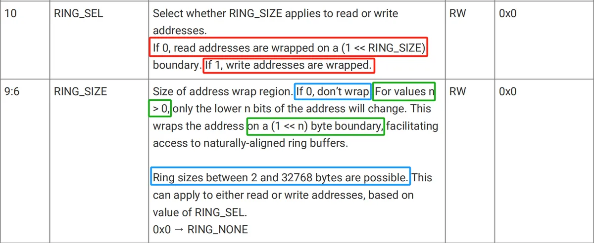
- Circular transmission means that the address pointer can wrap around to the start of the buffer at a predefined boundary, which is commonly used in data read and write operations related to the FIFO (First-In, First-Out) buffer of peripherals.
CTRL.RING_SELSelect whether to apply RING_SIZE to the read address or the write addressCTRL.RING_SIZEis used to set the size of the ring transmission data; the size of the ring buffer can be set to a value ranging from 2 to 32768 bytes. It should be noted that the value passed here corresponds to the number of data bits represented by the number of bytes in the buffer. Simply put, ifring_sizeis set to 8, the lowest 8 bits of the address register will change, which means the address will wrap around at a 256-byte boundary;the value of ring_sizeshould be an integer between 0 and 31
- Configure Chained Transmission (CTRL.CHAIN_TO):

CTRL.CHAIN_TOThe data bits are used to select another channel to be triggered when the current channel completes transmission: after a DMA channel finishes data transfer, it can automatically trigger the next DMA channel to continue the operation.- This method is called Channel Chaining, which is extremely useful in complex transmission scenarios, as it allows multiple DMA channels to execute sequentially without requiring CPU intervention.
- If
CTRL.CHAIN_TOis set to a certain channel number, the specified next channel will be automatically triggered when the current channel completes.
- Select Peripheral Data Request Signal (CTRL.TREQ_SEL):
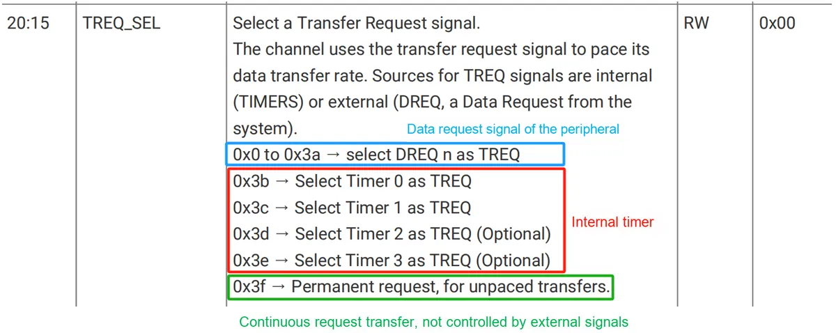
CTRL.TREQ_SELdata bits are used to select the data request signal of a peripheral (DREQ) to control the transfer rate of the DMA channel.DREQsignal is usually generated by a peripheral to request DMA to transfer data from the peripheral: for example, peripherals such as UART, SPI or I2C can generate such a request signal to control the DMA channel to transfer data at the appropriate timing so as to ensure data synchronization.- If no peripheral signal is selected, the DMA will not be limited by the data read/write speed of the peripheral, and will instead perform data transmission in accordance with the internal clock frequency of the DMA controller.
- Check whether the channel is idle (CTRL.BUSY):
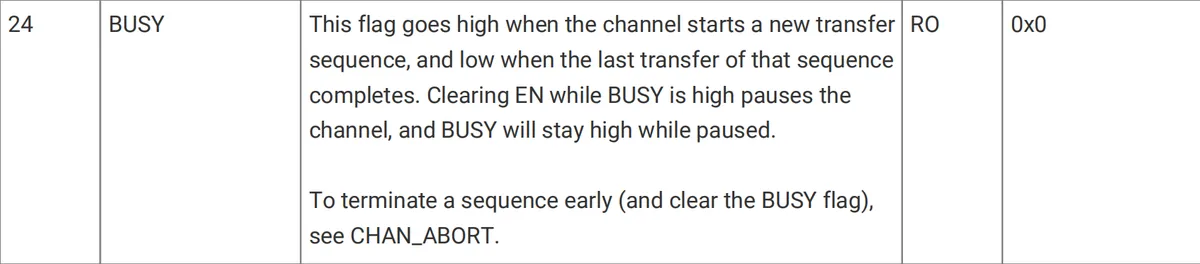
CTRL.BUSYThe data bit is used to indicate whether the DMA channel is currently busy performing a transfer operation:- When this data bit is
1, it indicates that the DMA channel is performing a transfer operation; - When this data bit is
0, it indicates that the channel is idle and can accept new transmission commands.
- When this data bit is
- By checking
CTRL.BUSY, the software can determine whether to submit a new transfer task or wait for the current task to complete - To terminate the transmission sequence in advance and clear the
BUSYflag, you can use theCHAN_ABORTregister
- Detection of bus errors (CTRL.AHB_ERROR, CTRL.READ_ERROR, CTRL.WRITE_ERROR): When any of the following error status bits is set, it indicates that a problem has occurred during the DMA transfer, which requires software-based debugging and error handling:
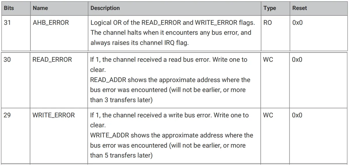
CTRL.AHB_ERRORThe data bit indicates whether an AHB error occurred during the transmission of the DMA channel, which may be caused by accessing an invalid address or an unsupported peripheral address space.CTRL.READ_ERRORThe data bit indicates whether an error occurred during DMA read, such as accessing an invalid memory location or peripheral address.CTRL.WRITE_ERRORThe data bit indicates whether an error occurred during DMA write, such as writing to an invalid memory location or peripheral address.
1.2.3 Start the DMA channel for data transmission
There are three ways to start a DMA channel:
- Write to the channel control trigger register: Start the channel by writing a value to the specific channel control trigger register. This method is simple and efficient, and is especially suitable for configuring and starting channels in Interrupt Service Routines (ISRs)

- Chained trigger (trigger from another channel): When a channel completes transmission, if the
CHAIN_TObit in its control status register is configured for chained triggering, it can trigger another channel to start; - Multi-Channel Trigger Register (MULTI_CHAN_TRIGGER): The multi-channel trigger register can be used to start multiple channels at one time, and this method is suitable for scenarios where multiple data transmissions need to be started simultaneously.
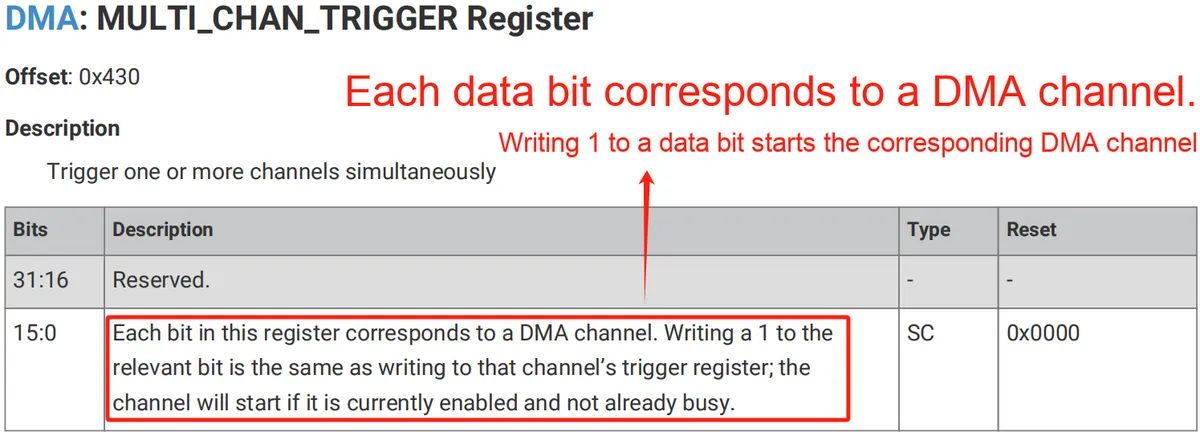
When starting a DMA channel, it should be noted that attempting to trigger a channel that is already running will have no effect.
1.2.3.1 Register Aliases and Trigger Mechanisms
Each DMA channel has four main Control and Status Registers (CSRs), which are as follows:
READ_ADDR: Read Address RegisterWRITE_ADDR: Write Address RegisterTRANS_COUNT: Transfer Count RegisterCTRL_TRIG: Control Trigger Register
These registers have four distinct sets of aliases in memory; accessing each set of aliases addresses the same physical registers, albeit arranged in a different order.
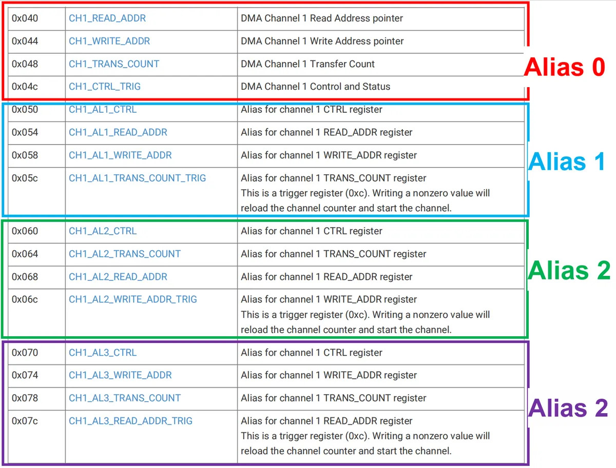
The following table shows the address offsets and arrangement order of these register aliases:
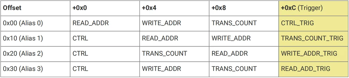
The last register of each alias (offset + 0xC) is the trigger register; writing to this register starts the DMA channel.
The main advantage of using aliases is that you can start a DMA channel by only writing to the key registers, without having to write to all configuration registers at once:
- When data is read from memory and transferred to a peripheral, you only need to write to
READ_ADDR_TRIG(the trigger register for the read address); this operation configures the read address and starts the DMA channel at the same time. - When data is transferred from a peripheral to memory, it is possible to only write to
WRITE_ADDR_TRIG(the trigger register for the write address); this operation simultaneously configures the write address and starts the DMA channel.
When performing chaining operations between DMA channels (i. e., starting another channel once one channel completes its task), aliasing enables transfer control to be implemented via a more compact control block list; with aliasing, there is no need to rewrite all registers — only those registers that have changed need to be written to:
(WRITE_ADDR, TRANS_COUNT_TRIG): This combination is used for the operation of scattering data from a peripheral to memory (scatter). The channel can be started simply by writing to the trigger registers for the write address and transfer count; the so-called data scatter refers to writing the data from the peripheral in a scattered manner into multiple memory blocks of fixed sizes.(TRANS_COUNT, READ_ADDR_TRIG): This combination is used to gather data from memory to a peripheral, which can also reduce the number of registers to be written, requiring only writing to the transfer count and read address trigger registers; the so-called data gathering refers to collecting multiple fixed-size memory blocks into the relevant registers of a peripheral (e. g., a serial port).
The DMA channel cannot be started in the following cases:
- Channel disabled: If the channel is disabled via the
CTRL.ENdata bit, writing to the trigger register will not activate the channel - The channel is already running: If the channel is already performing a transmission, the trigger operation will have no effect on it
- Write 0: When you write 0 to the trigger register, the channel will not be activated
1.2.3.2 Chained Triggering of DMA Channels
Chained triggering is a mechanism that allows one DMA channel to immediately trigger another channel upon completion of a transfer. In this way, the cooperative operation between two or more DMA channels can be realized. Common application scenarios include enabling one channel to immediately configure and start another channel after completing a transfer, and even reconfiguring the first channel through chained triggering.
Chain triggering is configured via the CTRL register of the DMA channel, specifically using the CHAIN_TO data bit field, which is a 4-bit value that specifies the target channel to be started after the current channel completes its transfer.

Note that a channel cannot trigger itself; if CHAIN_TO is set to the index of the channel itself, no chain triggering will occur. Chain triggering behaves the same as a trigger operation from other sources (such as a trigger register), and it will cause the target channel's transfer counter (TRANS_COUNT) to be reloaded.
Chain triggering has a wide range of applications, and the following are two typical scenarios:
- Channel reconfiguration: After one channel completes its task, another channel is reconfigured to restart the first channel. This method is commonly used in scenarios where multiple transmission tasks need to be completed sequentially.
- For example, Channel A is responsible for transferring data from the memory to the control registers of Channel B (including the trigger register of B), and after Channel B completes the task, it restarts Channel A via chaining trigger, thereby realizing the continuous execution of multiple tasks.
- In this process, the control block can be used to store the configuration of the DMA channel, and the chained structure of the control block makes the configuration and triggering process more compact and efficient: the control block is a structure for storing the configuration information of the DMA channel, which contains the key information required for each channel, such as the source address, destination address, transfer count and configuration of the control register.
- Ping-pong operation: After Channel A completes a task, it triggers Channel B, and after Channel B finishes the task, it triggers Channel A in turn. In this way, the two channels execute tasks alternately, creating a "ping-pong" effect. Under this configuration, the CPU can reconfigure the channels after they complete a task, while the chain-triggered channel is already pre-configured and can start immediately, thus realizing pipelined task processing. This process greatly improves the performance of short transmission tasks, as the channels do not need to wait for the CPU to complete reconfiguration.
1.2.3.3 Empty Trigger and Chain Interruption
In DMA control, a Null Trigger refers to the operation of writing an all-zero value to the trigger register; when an all-zero value is written to the trigger register, the channel will not be activated. This operation is called a "null trigger" and it mainly serves two purposes:
- Stop the execution of the control block sequence: At the end of the control block chain, the transfer process can be terminated by appending an all-zero control block; when the DMA channel reads the all-zero control block, since this is a null trigger, it will not continue to start the next control block, thus causing the transfer to stop, which is a method to realize automatic stop
- Reduce the number of interrupts: By default, whenever a channel completes a transfer sequence, it generates an interrupt unless the channel's interrupt is masked (via
INTE0orINTE1to mask the interrupt); however, when the control block sequence is very long, the interrupt frequency may become excessively high, imposing unnecessary burden on the processor. Especially when the processor does not require frequent intervention during the control block sequence, unnecessary interrupts can be reduced through null triggering, which only triggers an interrupt at the end of the control block chain.
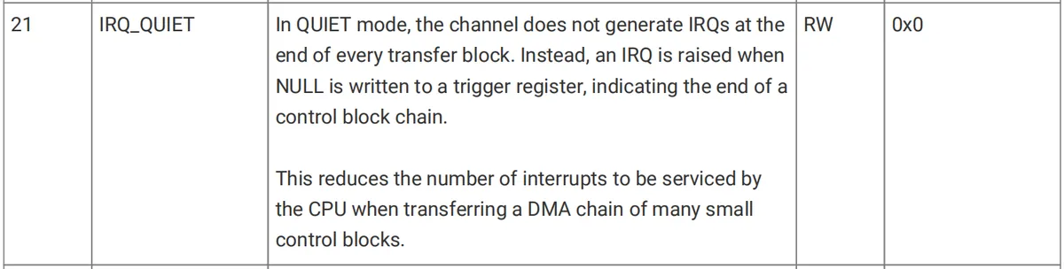
In the CTRL register of the DMA channel, there is a data bit named IRQ_QUIET whose default value is 0, meaning that an interrupt will be generated each time a transmission sequence is completed; if it is set to 1, the channel will only generate an interrupt when receiving an empty trigger, and will not generate an interrupt at any other time:
1.2.4 DMA Data Request
In embedded systems, peripherals (such as UART, SPI, ADC, etc.) generate or consume data at their respective rates, which are usually not fixed; to ensure stable data transmission and avoid data loss or corruption, the DMA (Direct Memory Access) controller introduces a mechanism called DREQ (Data Request).
DREQ serves as the communication channel between the peripheral and DMA to regulate the transmission speed, so as to synchronize the data transfer of DMA with the rate of the peripheral. Its main function is to allow the peripheral to inform the DMA whether data transmission can be continued currently or should be suspended temporarily:
- When a peripheral requires more data, it asserts a DREQ signal to inform the DMA that it may continue transferring data to the peripheral.
- When a peripheral is processing data or operating at full load, it will not assert the DREQ signal, so that the DMA pauses data transmission to avoid data overflow.
This mechanism can ensure that the peripheral will not lose data due to excessively fast transmission, or experience data accumulation due to excessively slow transmission.
In the CTRL.TREQ_SEL data bits of the DMA, you can configure how the DMA selects the source of the transfer request signal:
- External DREQ signal:
TREQ_SELdata bits select the DREQ signal of a specific peripheral, and the DMA adjusts the data transfer rate according to the transfer request signal of that peripheral to ensure matching with the peripheral's data throughput; for example, when the SPI peripheral is ready to receive data, it will assert a DREQ to notify the DMA to continue data transfer - Internal Timer: TREQ_SEL can also select the internal pacing timer of the DMA. In this mode, the DMA adjusts the transmission rate via the timer instead of relying on the DREQ signal from the peripheral, so as to meet the transmission requirements at a fixed rate, such as the transmission of audio data streams.
- TREQ not used (no DREQ): If TREQ_SEL is set to "TREQ not used"(i. e., no DREQ), the DMA will not rely on any external or internal pacing signals, and instead transmit data at the maximum speed. This mode is typically used for memory-to-memory transfers, as memory operations are generally fast enough that no rate control is required.
The following is the system DREQ table, which lists the DREQ channel numbers of various peripherals and their corresponding functions:
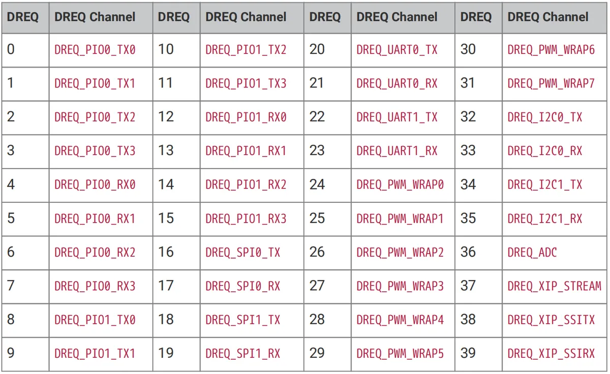
Wherein:
- DREQ_PIO0_TX0 to DREQ_PIO0_RX3: These DREQ channels are associated with the PIO (Programmable Input/Output) peripheral,
TXindicates that the data transmission direction is output,RXindicates that the data transmission direction is input - DREQ_PIO1_TX0 to DREQ_PIO1_RX3: These DREQ channels are associated with the PIO1 peripheral and function similarly to PIO0
- DREQ_UART0_TX and DREQ_UART0_RX: These DREQ channels are respectively used for data requests of the transmit (TX) and receive (RX) functions of the UART0 peripheral.
- DREQ_UART1_TX and DREQ_UART1_RX: Similar to the DREQ channels of UART0, they are used for data transmission and reception requests of the UART1 peripheral.
- DREQ_SPI0_TX and DREQ_SPI0_RX: These DREQ channels are respectively used for data transfer requests of the SPI0 peripheral;
TXindicates that the data transfer direction is output,RXindicates that the data transfer direction is input. - DREQ_SPI1_TX and DREQ_SPI1_RX: Similar to the DREQ channels of SPI0, they are used for data transfer requests of the SPI1 peripheral.
- DREQ_PWM_WRAP0 to DREQ_PWM_WRAP7: These DREQ channels are associated with the PWM (Pulse Width Modulation) peripheral and are primarily used to handle the period end requests of PWM.
- DREQ_I2C0_TX and DREQ_I2C0_RX: These DREQ channels are respectively used for data transfer requests of the I2C0 peripheral.
- DREQ_I2C1_TX and DREQ_I2C1_RX: Similar to the DREQ channels of I2C0, they are used for data transfer requests of the I2C1 peripheral.
- DREQ_ADC: This DREQ channel is associated with the ADC peripheral
- DREQ_XIP_STREAM, DREQ_XIP_SSITX and DREQ_XIP_SSIRX: These DREQ channels are associated with the XIP (eXecute In Place) peripheral and are used to handle streaming data and SPI transfer requests.
1.2.5 DMA Channel Interrupt
Each DMA channel can generate an interrupt, and the interrupt request is triggered under the following circumstances:
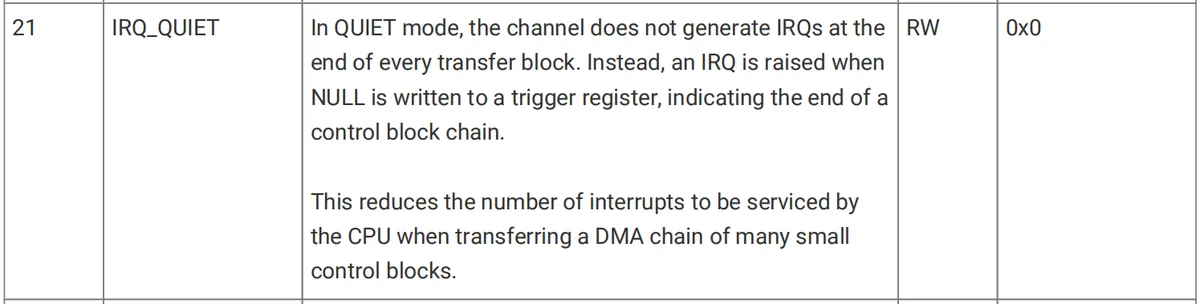
- When a transfer sequence completes: When a channel finishes a transfer sequence, it generates an interrupt request, which is triggered when
CTRL.IRQ_QUIETis disabled - When a Null Trigger is received: When the channel receives a null trigger signal and
CTRL.IRQ_QUIETis enabled, an interrupt request will also be generated
The DMA of the RP2040 provides two system interrupts (IRQs), each with independent mask and status registers (such as INTE0 and INTE1), and interrupt requests can be routed to either of these two system interrupts. We can route interrupt requests from different channels to different system interrupts as needed; for example, certain channels with strict timing requirements can be configured to have higher priorities, and in multi-processor systems, interrupts from different channels can be independently routed to different processing cores to achieve more efficient interrupt handling.
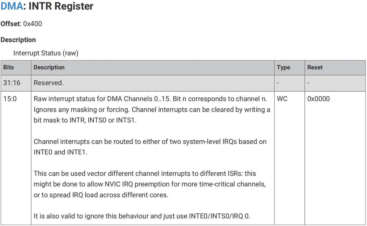
We can check the INTR register to obtain the raw interrupt status of the DMA channels; the 16 data bits provide the raw interrupt status for DMA channels 0 through 15:
We can check the masked interrupt status bits of each channel via the INTS register; to clear an interrupt, we can write a bit mask to INTS:
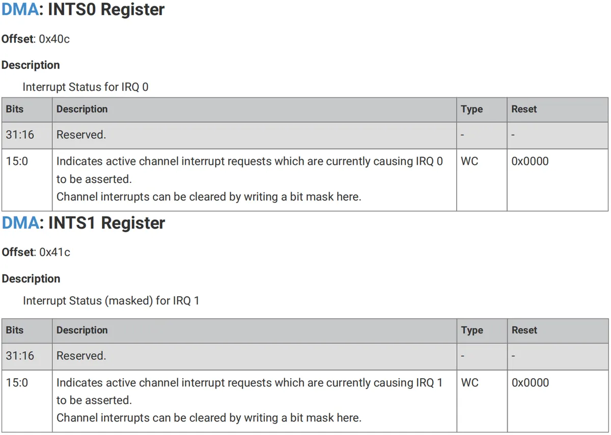
We can mask interrupts by channel by configuring the INTE register, which allows users to select which channel interrupts are valid. Users can set or clear bits in these registers to enable or disable interrupt requests for specific channels:
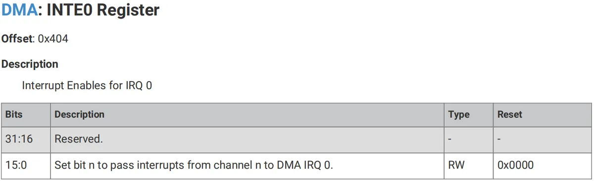
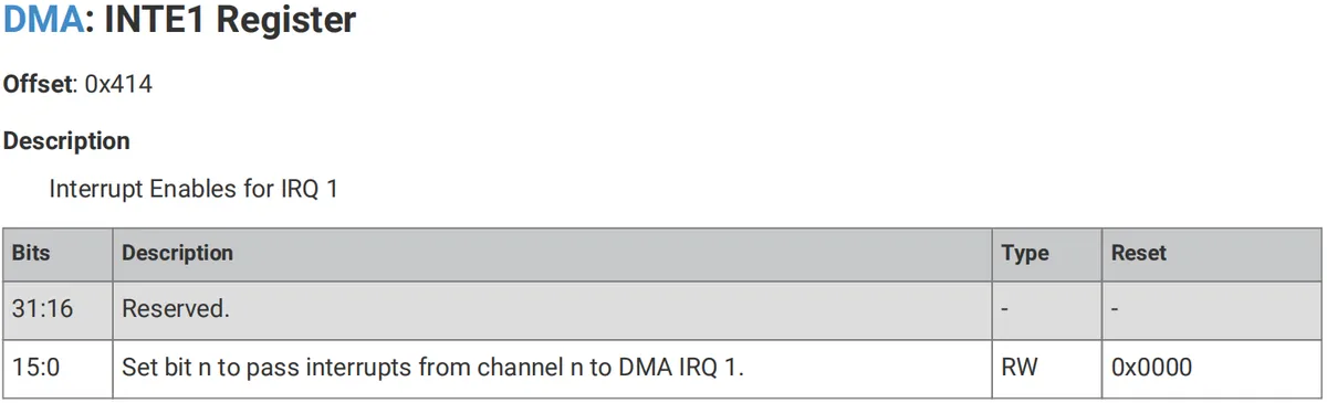
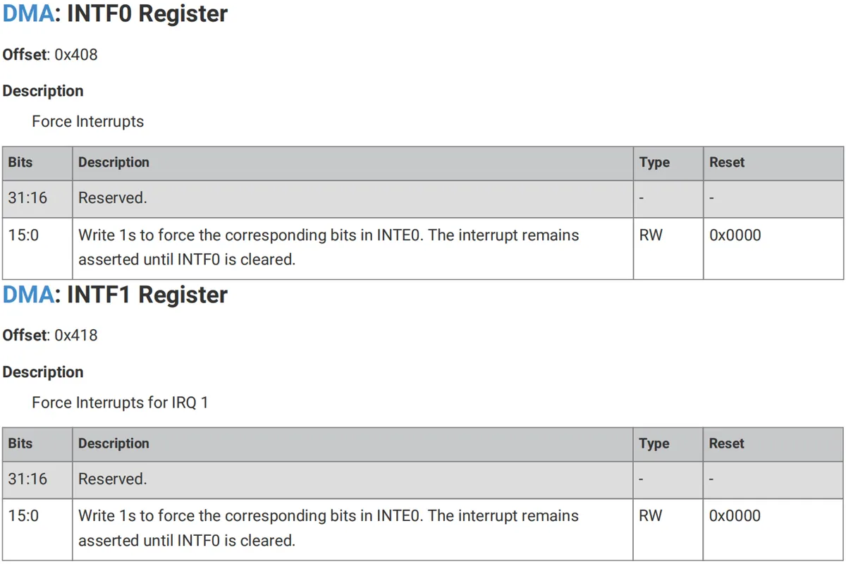
We can forcibly trigger a DMA interrupt by configuring the INTF register:
1.2.6 Other Features of DMA
1.2.6.1 Beat Timer
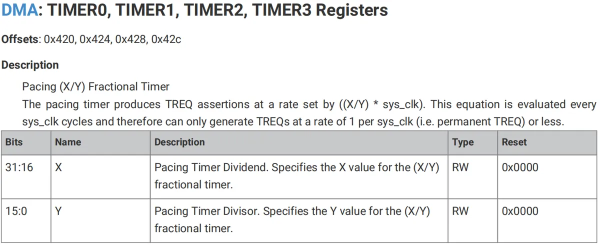
In the RP2040 microcontroller, the beat timer is used to control the rhythm of data transmission. It generates a data request (TREQ) at each clk_sys clock cycle without relying on the DREQ signal from an external peripheral. These timers use a fractional (X/Y) frequency divider to set the generation frequency of the requests.
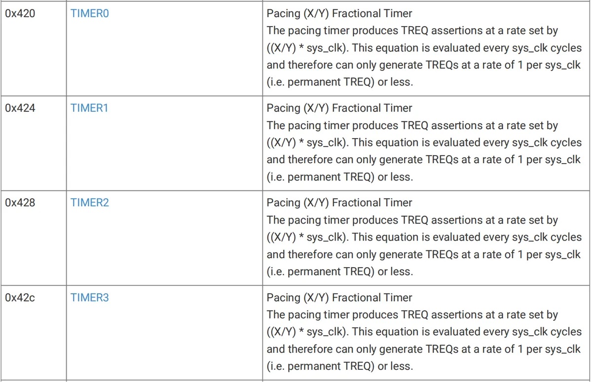
The maximum generation rate of each timer is one request per sys_clk cycle, and the generation rate of TREQ is ((X/Y) * sys_clk).
1.2.6.2 CRC Check
The DMA function incorporates a CRC calculator, which can compute the checksum as data passes through the data FIFO of the DMA channel; this feature operates in a passive manner, meaning it does not modify the data, but merely monitors the data and calculates the checksum.
We can configure the specific parameters of CRC calculation through the SNIFF_CTRL register, and configure the SNIFF_DATA register to set the specific details of data processing.
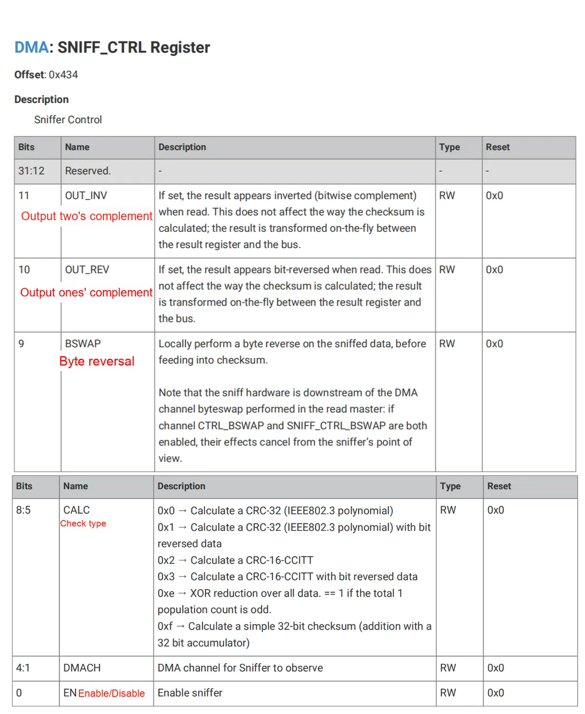
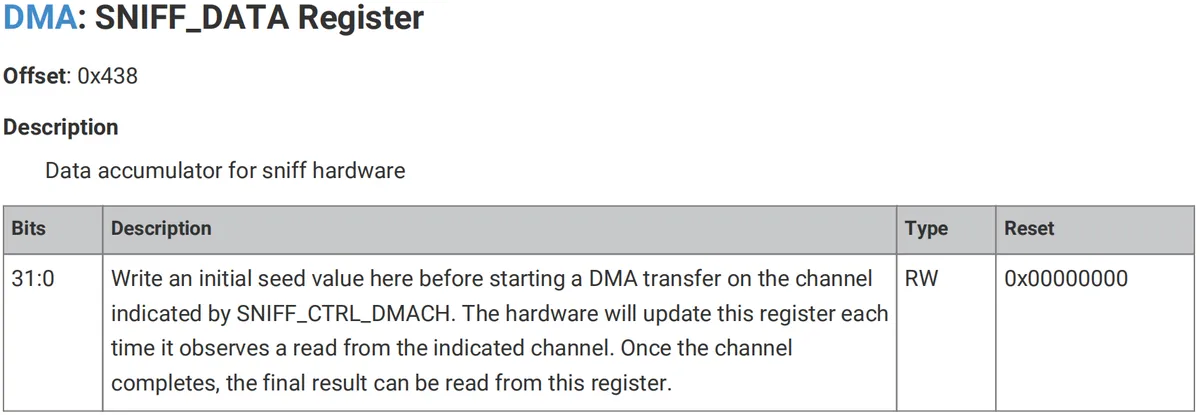
Here, DMA supports check types such as CRC-32, CRC-16-CCITT, simple summation, and even parity.
1.2.6.3 Channel Abort
In the RP2040 microcontroller, DMA channels may enter an unrecoverable state. For example, when a channel is instructed to transfer more data than the peripheral can request, it will be unable to complete the transfer. In this case, simply clearing the CTRL.EN bit only pauses the channel and does not resolve the issue. To recover from such problems without having to perform a hard reset of the entire DMA block, the channel abort mechanism must be used.
We can configure the CHAN_ABORT register to force a channel to complete prematurely: writing 1 to the data bit corresponding to a specific channel will clear the channel's transfer counter and set the channel to an inactive state. This method allows forcing the channel into a safe state when an unrecoverable error is encountered, thereby avoiding the need to reset the entire DMA block.
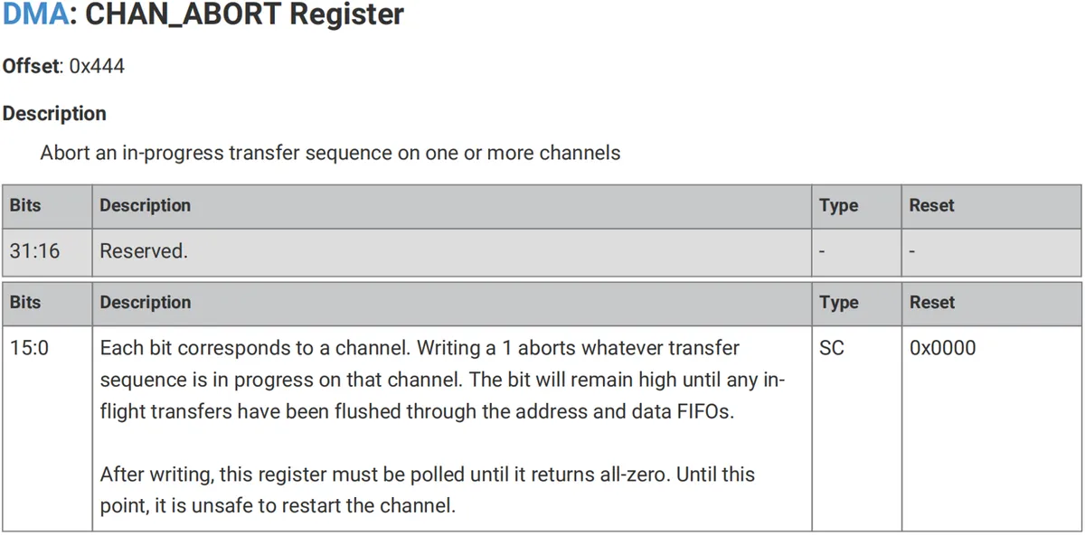
It should be noted here that due to the characteristics of the RP2040 chip, when aborting an ongoing DMA channel (that is, the channel is not suspended due to an inactive DREQ), it may cause the completion interrupt request (IRQ) to be triggered. Therefore, before performing the abort operation, the interrupt enable flag of the channel should be cleared first, and the interrupt should be checked and cleared after the abort operation.
When an abort operation is triggered, there may be ongoing bus transmissions on the channel. These transmissions cannot be revoked;the CTRL.BUSY flag will remain high until these transmissions complete and the channel reaches a safe state, a process that typically takes only a few clock cycles. The channel should not be restarted before its CTRL.BUSY flag goes low; starting a new transmission sequence while the old one is still in progress will result in unpredictable behavior.
1.2.6.4 Debugging
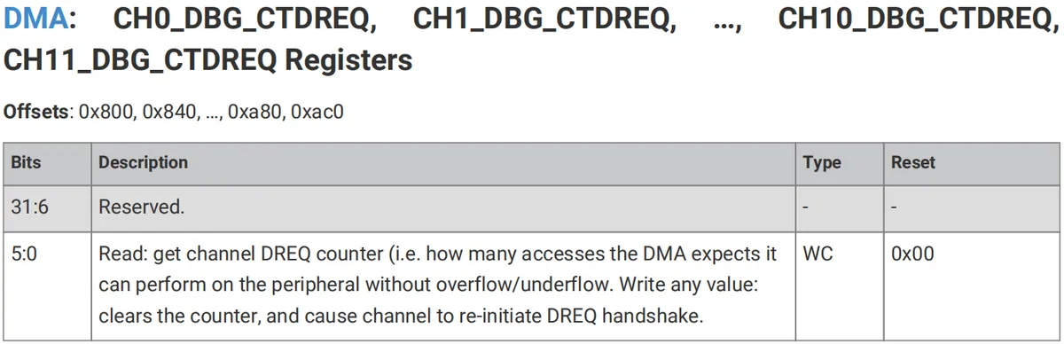
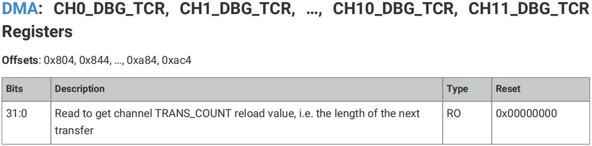
In the RP2040 microcontroller, each DMA channel is equipped with debug registers, which are used to display and debug the status of DMA operations; the debug registers include DBG_CTDREQ and DBG_TCR, which provide detailed information about the current status of the DMA channel and can be used to reset the DMA channel when necessary.
DBG_CTDREQ register is used to display the current value of the DREQ (transfer request) counter for the DMA channel:
DBG_TCR register is used to display the value of the current transmission counter:
2. Software Control Method
2.1 Constructor Method of the rp2.DMA Class
The constructor of the rp2.DMA class is as follows:
rp2.DMA()
Instantiate a DMA controller channel.
2.2 Other Methods of the rp2.DMA Class
The rp2.DMA class has other methods:
Method | Description |
DMA.config(read=None, write=None, count=None, ctrl=None, trigger=False) | Configure the DMA channel, which is used to set the read/write address, transfer count and control parameters, and supports optional immediate transfer triggering. The descriptions of the parameters are as follows:
|
DMA.irq(handler=None, hard=False) | Returns the interrupt object of the DMA channel and allows configuration of the interrupt handler. Through this method, you can monitor the status of the DMA channel and trigger an interrupt when the transfer is completed or an error occurs. The parameters are defined as follows:
|
DMA.close() | This method is used to release the occupancy of the DMA channel and unbind the interrupt handler; after calling this method, the current DMA object will be unavailable and you must reinitialize it or create a new DMA object to proceed with subsequent operations. |
DMA.pack_ctrl(default=None, **kwargs) | Pack the value of the DMA control register, where the control parameters include transfer size, address increment, etc. The optional parameters are as follows:
|
DMA.unpack_ctrl(value) | Unpack the DMA control register value and return a dictionary containing all control data bits. The parameters are defined as follows:
The returned Attribute–Value Pair data bits are as follows:
|
DMA.active([value]) | Query or set whether the DMA channel is in an active state. |
2.3 Attributes of the rp2.DMA Class
The rp2.DMA class also has several methods:
Attribute | Description |
DMA.read | The DMA.read property reflects the read address for the next bus transfer operation. This property can be assigned an integer address or an object that supports the buffer protocol (such as bytearray, memoryview, etc.), and the assignment takes effect immediately. |
DMA.write | The DMA.write property reflects the write address for the next bus transfer operation. This property can be assigned either an integer address or an object that supports the buffer protocol, and the assignment takes effect immediately. |
DMA.count | Used to read or set the transfer count of the DMA channel:
|
DMA.ctrl | Reflects the current value of the DMA control register, which can be packaged and written via |
DMA.channel | Returns the current DMA channel number, which can be used for DMA linking. |
DMA.registers |
|
3. Application Examples
3.1 DMA Class Implements Memory-to-Memory Data Transfer
The following code can be found in the elegance-devkit v1\Demo\66 DMA_MemoryToMemory folder within the resource package we provide.
In the following code, we use DMA to transfer data from a source array to a destination array, which eliminates the need for the CPU to participate in copying each byte, thus reducing the CPU workload and improving transmission efficiency. Meanwhile, we also compare the time-consuming difference between DMA transfer and array slice copying.
The sample code is as follows:
# Python env   : MicroPython v1.23.0
# -*- coding: utf-8 -*-
# @Time    : 2024/9/7 10:50 AM
# @Author  : Li Qingshui
# @File    : main.py
# @Description : DMA experiment, memory-to-memory transfer

# ======================================== Import Modules =========================================

# Import the DMA controller from the rp2 library
from rp2 import DMA
# Import the addressof function, used to get the memory address of data
from uctypes import addressof
# Import the array module, used to create arrays
from array import array
# Import time-related modules
import time

# ======================================== Global Variables ============================================

# Create an array as the source data, with data type unsigned 32-bit integers (I), and initialize the data
# From 0 to 1023, 1024 elements in total
source_data = array("I", range(1024))
# Create another array as the destination data, initialized as empty data space with the same size as the source data
destination_data = array("I", [0] * len(source_data))

# ======================================== Functions ============================================

# ======================================== Custom Classes ============================================

# ======================================== Initialization ==========================================

# Power-on delay of 3 s
time.sleep(3)
# Print debug information indicating the start of the main program
print("FreakStudio: DMA Memory to Memory Test ")

# Initialize the DMA object
dma = DMA()

# Set the DMA control register, using the pack_ctrl method to pack the control register; size=2 means transferring 32-bit words
ctrl = dma.pack_ctrl(size=2)

# Configure the DMA control register to set the data transfer mode
dma.config(
    read=addressof(source_data),        # Specify the source address (memory address of the source data)
    write=addressof(destination_data),  # Specify the destination address (memory address of the destination data)
    count=len(source_data),             # Length of data to transfer (in number of elements)
    ctrl=ctrl,      # Control register configuration
    trigger=False   # Do not start the transfer immediately
)

# ========================================  Main Program  ==========================================

# Print debug data, start DMA transfer
print("Start DMA")

# Test DMA transfer speed
# Record start time
start_time = time.ticks_us()
# Start DMA transfer
dma.active(1)
# Check whether DMA has finished the transfer; the transfer is complete when dma.count is 0
while dma.count > 0:
    pass
# Record end time
end_time = time.ticks_us()
# Calculate elapsed time
dma_time = time.ticks_diff(end_time, start_time)
print("DMA Transfer Time (us): ", dma_time)

# Print debug data to indicate the transfer is complete
print("DMA Finished")

# Print the destination data after the transfer to verify it is correct
print("Source Data: ", source_data)
print("Destination Data: ", destination_data)

# Test array slice copy speed
start_time = time.ticks_us()
destination_data[:] = source_data[:]
end_time = time.ticks_us()
array_time = time.ticks_diff(end_time, start_time)
print("Array Slice Copy Time (us): ", array_time)
Here, we first create two arrays:
source_data: An array containing 1024 elements is created, with the data type beingunsigned 32-bit integer, which means each element occupies 4 bytes, and the array holds the sequence from 0 to 1023 (a total of 1024 elements);destination_data: This array is used to receive the data after DMA transfer. During initialization, all elements are 0, and its length is the same as that ofsource_data.
Then configure the created DMA channel object:
- Set the DMA control register via the
pack_ctrlmethod:size= 2indicates 32-bit data transmission. This method encapsulates the configuration of the DMA control register, including control information such as transmission word length and direction. We can use theunpack_ctrlmethod to view its complete configuration

It can be seen that we set its read address and write address to increment, do not generate an interrupt at the end of each transmission but generate an interrupt after reading a zero value, and the data size of a single transmission is four bytes (32-bit data)
dma.config ()configures the transmission parameters of DMA: the source address is set to the memory address of thesource_dataarray, the destination address is set to the memory address of thedestination_dataarray, the length of data to be transmitted is set to the number of elements of the source data, i. e., 5 32-bit elements, the control register value generated by thepack_ctrlmethod is used, the transmission size is configured as 32 bits, and it is configured not to start transmission immediately- Here,
trigger= Truemeans that the DMA transfer will be started immediately. - When
trigger= False, you need to manually call thedma.active (1)method to initiate the transmission.
Both are software methods used to initiate DMA transfers.
- Here,
In the main program, after starting the DMA transfer, we use while dma.count > 0: to check whether the transfer is completed. dma.count indicates the number of data remaining to be transferred by DMA; when it becomes 0, the transfer is complete. Finally, we print the source data and destination data to verify whether DMA has successfully transferred the data from the source array to the destination array.
At the same time, record and proofread the time consumed by DMA transmission, and then test the array slice copying speed.
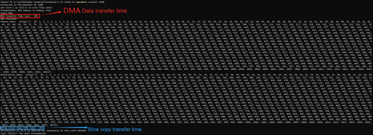
Burn the code, and the output is as follows:
3.1 Application Experiment.mp4 19.5 MB
As can be seen, we have successfully implemented data transfer from memory to memory using DMA, and the time taken for 1024 elements is 104 us, while the time taken for the slice copy operation is 314 us. When dealing with a large amount of Big data, the DMA data transfer speed is much faster than that of the slice copy operation; if we increase the data length to 4096 elements, the time taken for DMA transfer is 110 us, and the time taken for the slice copy operation is 923 us, making the speed difference even more pronounced.
Direct assignment is essentially reference copying
Here, a common pitfall to note is that in Python, destination_data = source_data does not copy the data; instead, it makes destination_data and source_data point to the same memory address, which means modifying the content in either destination_data or source_data will simultaneously affect the other variable.
The above code implements copying the content of source_data byte by byte to destination_data; the two occupy different Memory Spaces and do not affect each other.
3.2 DMA Class Implements Memory-to-Peripheral Data Transfer
3.2.1 Preparations Before the Experiment
In the following code, we have customized a DMA_UART_Tx class, which is used to implement efficient serial data transmission via UART and DMA on the Raspberry Pi Pico. DMA transfers data from the source address (memory) to the destination address (the UART data register).
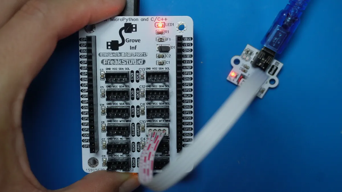
In the following experiment, we need to insert the Fengya No.1 board-Grove interface expansion board into the Fengya No.1 board-universal compatible expansion board , and use the HY2.0-4P wiring to connect the Fengya No.1 board-Grove interface expansion board 's UART1 interface and GraftSense-based USB to TTL module based on CH340K 's UART1 interface:
Then use a USB-A to Mini USB data cable to connect the USB port on the GraftSense - USB to TTL module based on CH340K to the computer. The physical connection diagram is shown below:
In addition, we first need to connect the MiniUSB data cable to the serial port on Fengya No. 1 Board - Universal Compatible Expansion Board. Here, GP0 and GP1 are the default pins of the hardware serial port UART0 of the Raspberry Pi Pico:
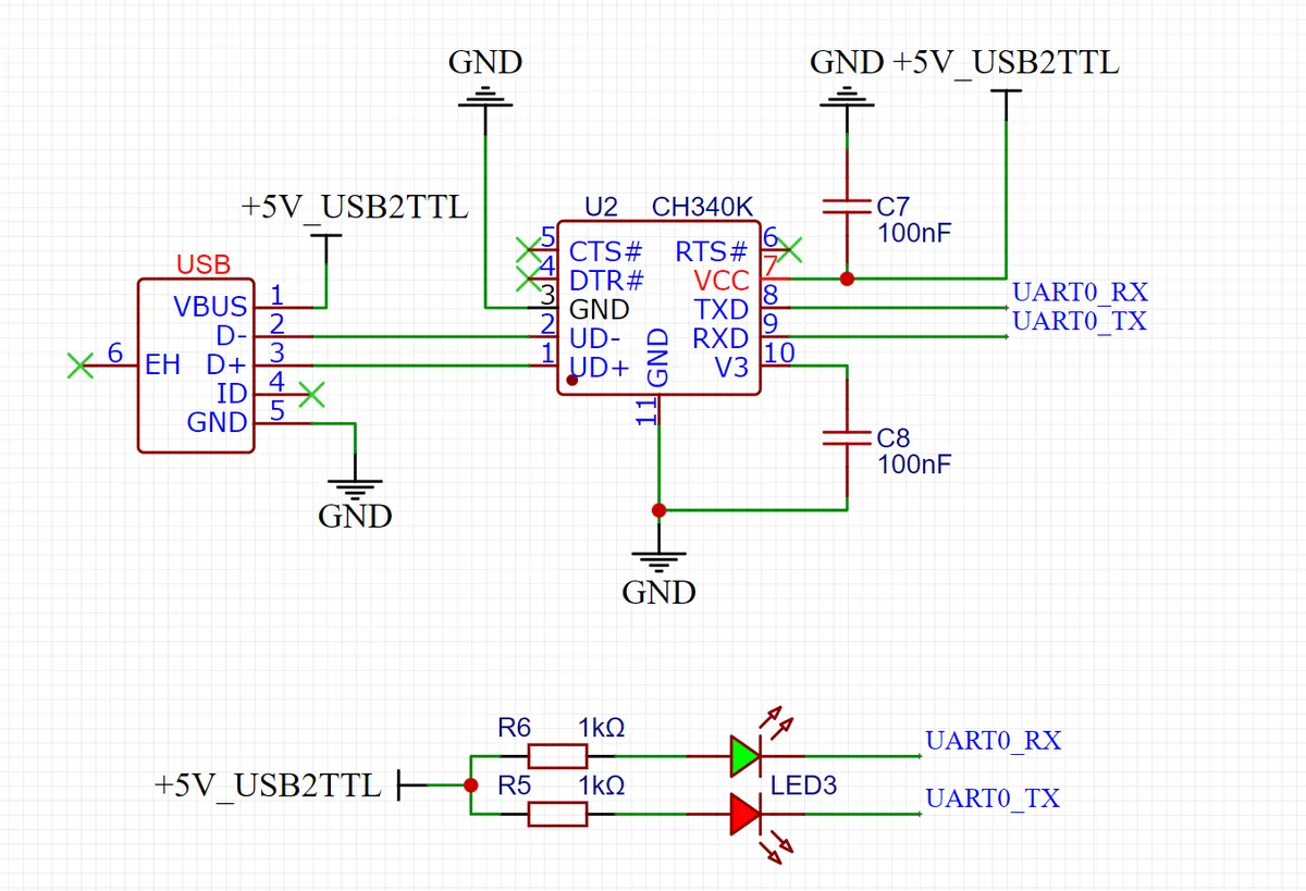
The physical image after insertion is as follows:
The pin connections are as follows:
Raspberry Pi Pico GPIO Pins | Connected electronic modules | Description of Application |
GP0 | Onboard USB-to-TTL chip | serves as the TX (transmit) pin of UART0 |
GP1 | Onboard USB-to-TTL chip | serves as the RX (receive) pin of UART0 |
GP4 | External USB-to-TTL module | Serve as the side set pins and output pins (for transmission) of finite-state machine 0 |
GP5 | External USB-to-TTL module | Connect to an external USB-to-TTL module (presumably the receiving pin) |
3.2.2 Implementation of Custom Serial Port DMA Transmission Class
Here, we first place the custom UART serial port DMA transmission class into a separate file:
# Python env   : MicroPython v1.23.0
# -*- coding: utf-8 -*-
# @Time    : 2024/9/7 11:56 PM
# @Author  : Li Qingshui
# @File    : dma_uart_tx.py
# @Description : Custom UART DMA transfer

# ======================================== Import Modules =========================================

# Import the DMA controller from the rp2 library
from rp2 import DMA
# Import time-related modules
import time
# Import hardware-related modules
from machine import UART
# Import the module for reading and writing 32-bit memory
from machine import mem32
# Import the addressof function, used to get the memory address of data
from uctypes import addressof

# ======================================== Global Variables ============================================

# ======================================== Functions ============================================

# ======================================== Custom Classes ============================================

# Custom DMA UART transmit class: uses DMA to transfer data to the UART for sending
class DMA_UART_Tx:
    """
    DMA_UART_Tx class, used to transfer data to the UART through DMA (Direct Memory Access) for sending.
    This class wraps the configuration and operation of DMA and UART, and supports a transfer mode with 8 data bits, no parity bit, and 1 stop bit.
    UART0 is used by default, with a baud rate of 115200, TX pin 0, and RX pin 1.

    Attributes:
        uart_num (int): UART number, 0 for UART0, 1 for UART1.
        baudrate (int): Baud rate, default is 115200.
        tx_pin (int): TX pin number, default is 0.
        rx_pin (int): RX pin number, default is 1.
        uart (UART): UART instance, used to configure and operate the UART.
        dma (DMA): DMA instance, used to configure and operate the DMA.
        UART_BASE (int): UART register base address.
        UART_UARTDR (int): UART data register address.
        UART_UARTFR (int): UART flag register address.
        UART_UARTDMACR (int): UART DMA control register address.

    Methods:
        __init__(self, uart_num=0, baudrate=115200, tx_pin=0, rx_pin=1):
            Initialize the DMA UART class.
        is_transmit_fifo_full(self):
            Check whether the UART transmit FIFO is full.
        is_transmit_fifo_empty(self):
            Check whether the UART transmit FIFO is empty.
        is_buffer_protocol(obj):
            Determine whether an object is a buffer protocol object.
        enable_uart_tx_dma(self):
            Enable the UART transmit DMA function.
        dma_transmit(self, buf, wait_func=None, callback=None, blocking=False):
            Use DMA to transfer data to the UART.
    """
    def __init__(self, uart_num: int = 0, baudrate: int = 115200, tx_pin: int = 0, rx_pin: int = 1) -> None:
        """
        Initialize the DMA UART class. Currently only the transfer mode with 8 data bits, no parity bit, and 1 stop bit is supported.
        UART0 is used by default, with a baud rate of 115200, TX pin 0, and RX pin 1.

        Args:
            uart_num (int): Select UART0 or UART1, default is 0.
            baudrate (int): Baud rate, default is 115200.
            tx_pin (int): TX pin number, default is 0.
            rx_pin (int): RX pin number, default is 1.

        Raises:
            ValueError: If the UART number or baud rate is invalid.
        """
        # Check whether the UART is available
        if uart_num not in (0, 1):
            raise ValueError("UART number must be 0 or 1")
        # Check whether the baud rate is a valid value
        if baudrate not in (9600, 19200, 38400, 57600, 115200, 230400, 460800, 921600):
            raise ValueError("Invalid baudrate")

        self.uart_num = uart_num
        self.baudrate = baudrate
        self.tx_pin = tx_pin
        self.rx_pin = rx_pin

        # Initialize UART
        self.uart = UART(self.uart_num, baudrate=self.baudrate, tx=self.tx_pin, rx=self.rx_pin)
        self.uart.init(baudrate=self.baudrate, bits=8, parity=None, stop=1, timeout=100)

        # Initialize DMA
        self.dma = DMA()

        # Define UART register addresses: for UART0 the address is 0x40034000, otherwise 0x40038000
        self.UART_BASE = 0x40034000 if self.uart_num == 0 else 0x40038000

        # Address information of the UARTDR, UARTFR, UARTCR and UARTDMACR registers in the UART peripheral
        self.UARTDR_OFFSET = 0x000
        self.UARTFR_OFFSET = 0x018
        self.UARTDMACR_OFFSET = 0x048

        self.UART_UARTDR = self.UART_BASE + self.UARTDR_OFFSET
        self.UART_UARTFR = self.UART_BASE + self.UARTFR_OFFSET
        self.UART_UARTDMACR = self.UART_BASE + self.UARTDMACR_OFFSET

        # Enable the DMA transfer function
        self.enable_uart_tx_dma()

    def is_transmit_fifo_full(self) -> bool:
        """
        Check whether the UART transmit FIFO is full.

        Returns:
            bool: True means full, False means not full.
        """

        # Read the value of the UARTFR register
        reg_value = mem32[self.UART_UARTFR]
        # Extract the value of the TXFF bit (bit 5)
        txff_bit = (reg_value >> 5) & 0x1

        # Determine whether the TXFF bit is 1 (whether the FIFO is full)
        return txff_bit == 1

    def is_transmit_fifo_empty(self) -> bool:
        """
        Check whether the UART transmit FIFO is empty.

        Returns:
            bool: True means empty, False means not empty.
        """

        # Read the value of the UARTFR register
        reg_value = mem32[self.UART_UARTFR]
        # Extract the value of the TXFE bit (bit 7)
        txfe_bit = (reg_value >> 7) & 0x1

        # Determine whether the TXFE bit is 1 (whether the FIFO is empty)
        return txfe_bit == 1

    @staticmethod
    def is_buffer_protocol(obj: object) -> bool:
        """
        Determine whether an object is a buffer protocol object.

        Args:
            obj (object): The object passed in.

        Returns:
            bool: Returns True if it is a buffer protocol object, otherwise False.
        """
        try:
            # Try to use memoryview to create a buffer view of the object
            memoryview(obj)
            return True
        except TypeError:
            return False

    def enable_uart_tx_dma(self) -> None:
        """
        Enable the UART transmit DMA function by setting the TXDMAE bit of the UARTDMACR register.
        """
        reg_value = mem32[self.UART_UARTDMACR]
        reg_value |= (1 << 1)
        mem32[self.UART_UARTDMACR] = reg_value

    def dma_transmit(self, buf: object, wait_func: callable = None, callback: callable = None,
                     blocking: bool = False) -> int:
        """
        Use DMA to transfer data to the UART.

        Args:
            buf (object): The byte data to transfer; must be a buffer protocol object.
            wait_func (callable): Callback function called while the transfer is in progress, optional.
            callback (callable): Callback function called when the transfer is complete, optional.
            blocking (bool): Whether to block and wait for the transfer to complete, optional, default is False.

        Returns:
            int: Elapsed time, in microseconds.

        Raises:
            Exception: If wait_func is passed in non-blocking mode, or buf is not a buffer protocol object.
        """

        # If non-blocking mode is selected, wait_func should not be passed in
        if blocking == False and wait_func is not None:
            raise Exception("Blocking mode should not have wait_func!")

        # Determine whether buf is a buffer protocol object
        if DMA_UART_Tx.is_buffer_protocol(buf) == False:
            raise Exception("buf must be a buffer protocol object!")

        # 20 is the number of the DREQ_UARTO_TX request signal, 22 is the number of the DREQ_UART1_TX request signal
        UART_DREQ = 20 if self.uart_num == 0 else 22

        # Set the DMA control register
        ctrl = self.dma.pack_ctrl(enable=True,          # Enable DMA
                                  size=0,               # Single transfer size of 8 bits (byte)
                                  inc_read=True,        # Read address increments
                                  inc_write=False,      # Write address does not increment
                                  treq_sel=UART_DREQ    # Set the DMA trigger signal
                                  )

        # Configure DMA
        self.dma.config(read=addressof(buf),     # Source address, i.e. the memory address of the data buffer
                        write=self.UART_UARTDR,  # Destination address, i.e. the address of the UART data register
                        count=len(buf),          # Number of bytes to transfer
                        ctrl=ctrl,               # DMA control register configuration
                        trigger=True             # Trigger the DMA transfer immediately
                        )

        # Record start time
        start_time = time.ticks_us()
        # Start DMA transfer
        self.dma.active(1)

        # Blocking mode, wait for the DMA transfer to complete
        if blocking == True:
            # Wait for the DMA transfer to complete
            while self.dma.active():
                # Check whether the TXFE bit of the UARTFR register is set
                if not self.is_transmit_fifo_empty():
                    # If the TXFE bit is not 1, the FIFO is not empty
                    if wait_func is not None:
                        # Execute the user-defined callback function
                        wait_func()

        if callback is not None:
            # Wait for the DMA transfer to finish, then execute the user-defined callback
            callback()

        # Record end time
        end_time = time.ticks_us()  # Record end time
        # Return elapsed time
        return time.ticks_diff(end_time, start_time)

# ======================================== Initialization ==========================================

# ========================================  Main Program  ===========================================
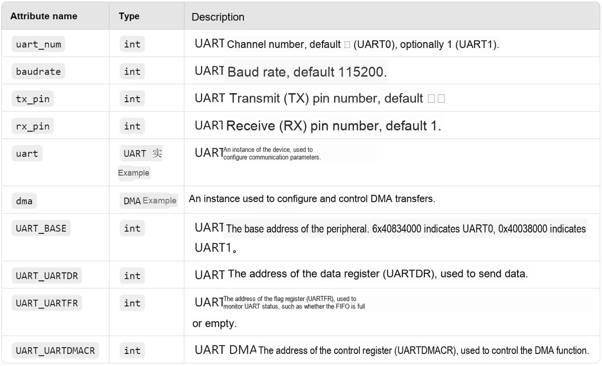
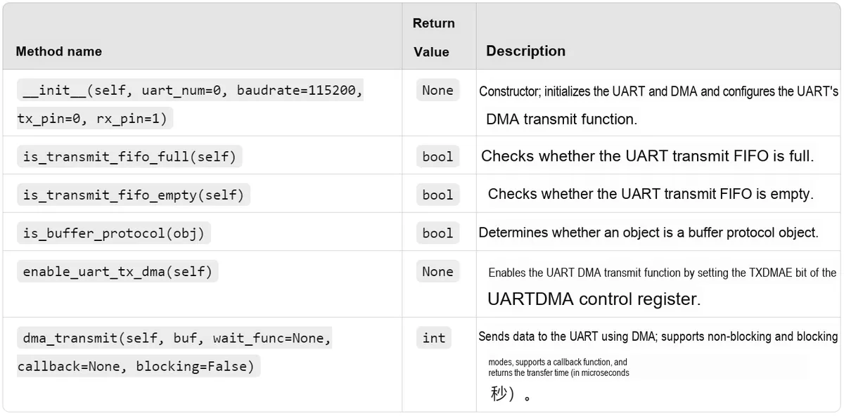
DMA_UART_Tx class provides the following methods and properties:
DMA_UART_Txclass attributes:
DMA_UART_Txclass methods:
Steps to implement data transfer between memory and peripherals using DMA
Here, when we use DMA to implement mutual data transmission between memory and peripherals, the general steps can be summarized as follows:
- Enable the DMA mode and DMA request signal of the peripheral: Enable the DMA function and DMA request signal by configuring the corresponding register (
DREQ), which is sent by the peripheral to the DMA controller to indicate that the peripheral has data to be transferred - Enable and configure the FIFO of the peripheral: Set the corresponding registers to enable the FIFO, and configure the FIFO trigger threshold; the DMA can automatically write data from the memory to the FIFO or read data from the FIFO to the memory according to the full/empty status of the FIFO
- Use DMA to complete data transmission between the peripheral and its corresponding FIFO register: configure the source address and destination address of the DMA controller data transmission, set the transmission direction and data size, and then start the DMA transmission
Here, let’s first take a look at the structure of the UART peripheral in the Raspberry Pi Pico:
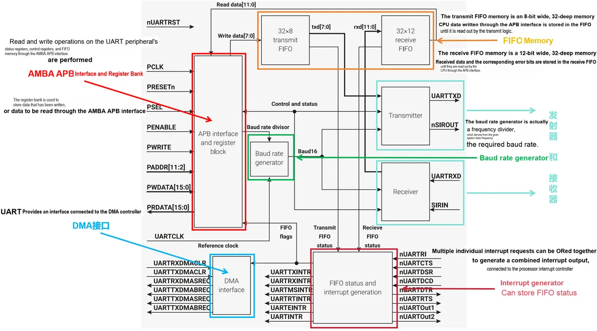
Here, the 32x8 transmit FIFO and 32x12 receive FIFO shown in the diagram are part of the UART hardware module, but they are not exposed to the user in the form of direct standalone registers. We need to indirectly operate the FIFO via UARTDR (the data register), which allows reading and writing data, and manages the queue operations of the FIFO buffer through internal hardware: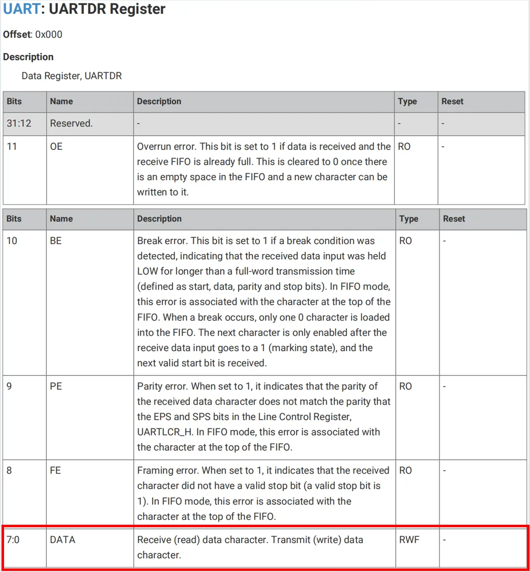
- Writing to the DATA data bits of the
UARTDRregister enables serial port transmission. - Read
the DATA bits of the UARTDRregister: to read the data received via the serial port
By configuring the UARTLCR_H register, the FIFO of the UART can be enabled:
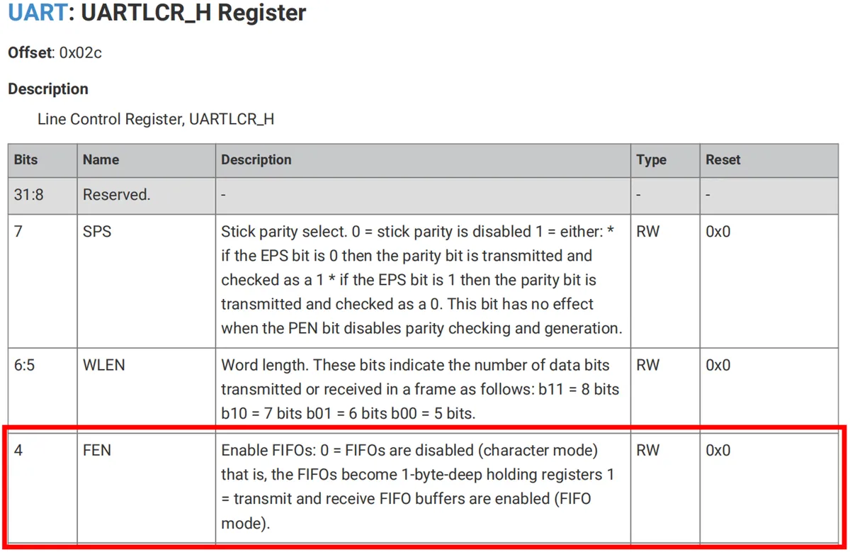
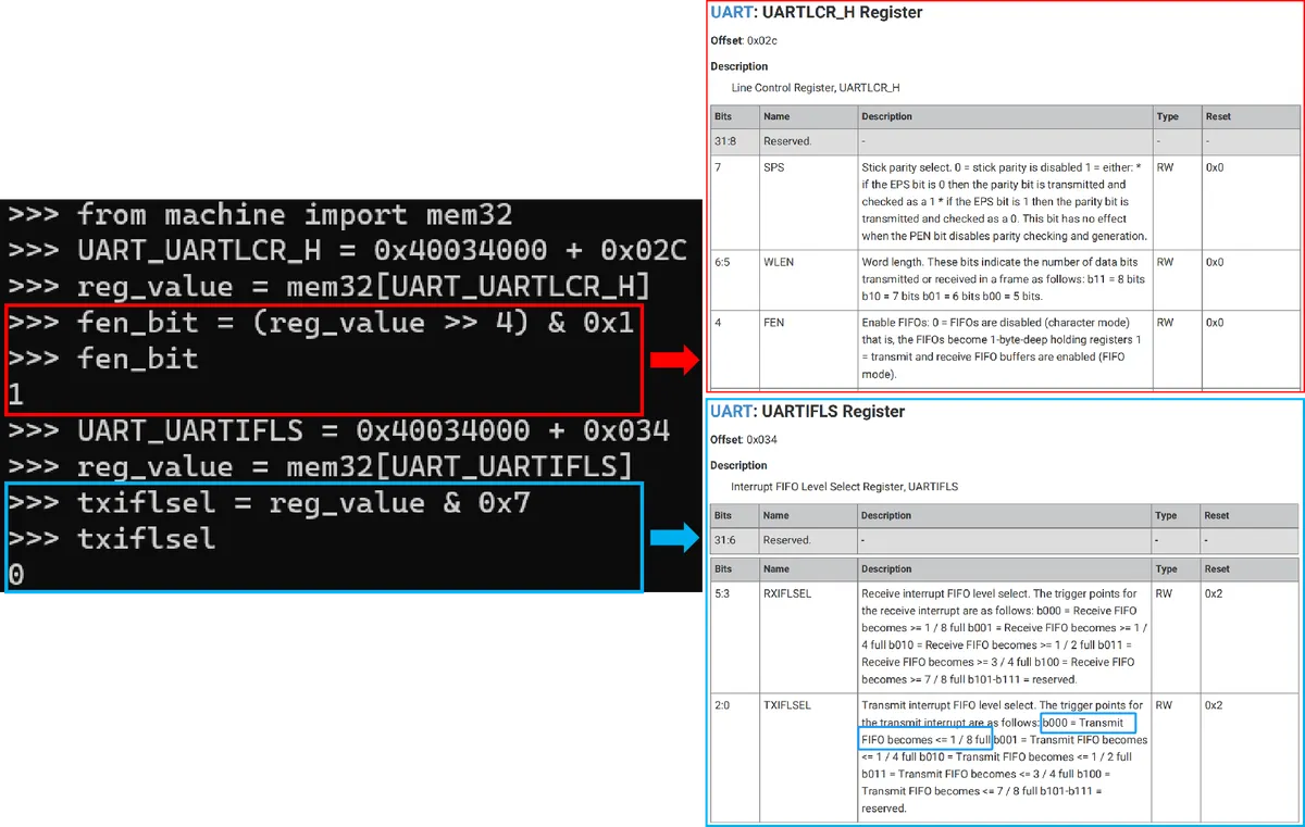
Actually, after creating and configuring an instance of the UART class in MicroPython, the FIFO and the FIFO interrupt trigger threshold have already been enabled:
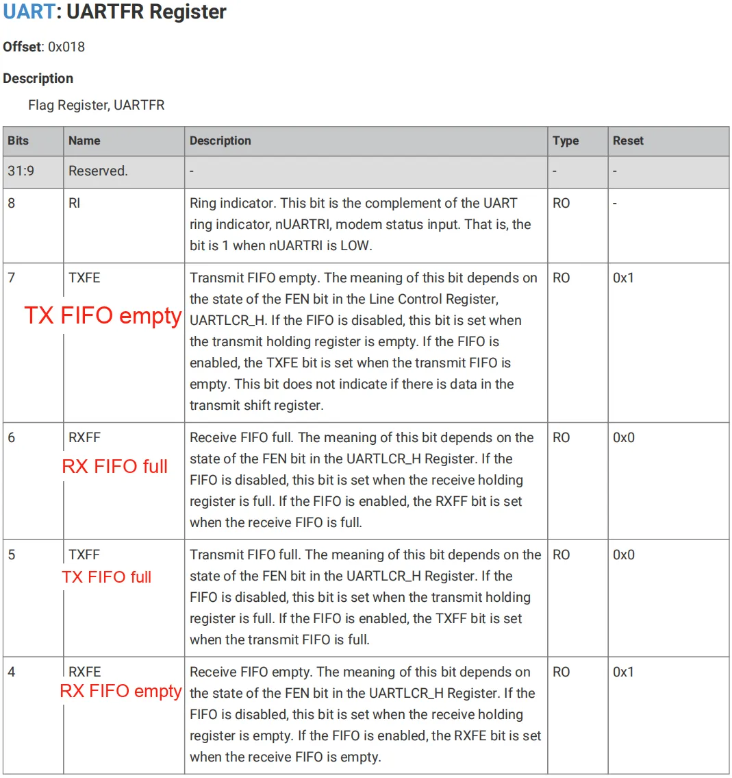
The status of the FIFO is typically monitored via the flag register UARTFR (Flag Register), which contains flag bits indicating whether the FIFO is empty or full. Accordingly, the status of the FIFO can be determined by reading these flag bits, so as to perform corresponding data transmission operations:
The DMA in the serial port peripheral controls and coordinates data transmission via UARTDMACR, and we need to enable its TXDMAE data bit here:
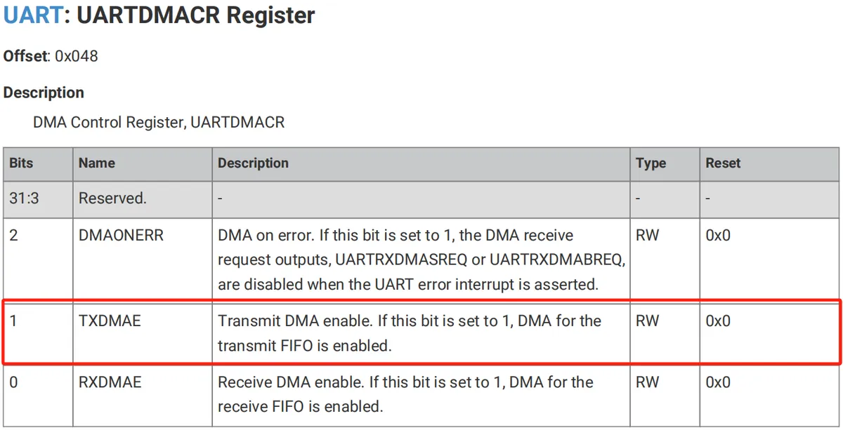
Here, the process of implementing DMA data transmission for the UART peripheral via DMA is as follows: first, enable the TXDMAE data bit in the transmit DMA of the UART peripheral, then use DMA to continuously enable the DATA data bit of the UARTDR register for data transfer from memory to the UART peripheral.
When initializing the DMA_UART_Tx class, we perform the following operations: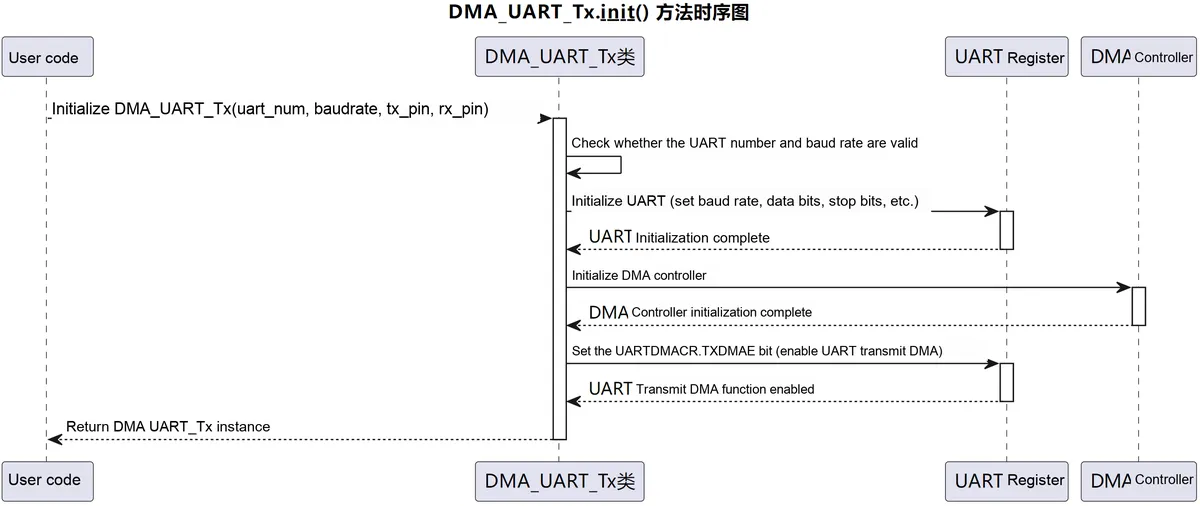
- Initialize the UART configuration, specify the UART interface to be used (
uart_num), communication baud rate (baudrate), as well as the transmit (tx_pin) and receive pins (rx_pin). - Initialize the serial port using the
UARTclass in MicroPython.self.uart_numdetermines which UART interface to use,baudratesets the communication rate,tx_pinandrx_pinspecify the pins to be used. Then, use the initialization method to configure the serial port peripheral parameters as 8 data bits, no parity bit, 1 stop bit, and set the timeout to 100ms. - Create a DMA object to prepare for subsequent memory-to-UART transfer operations via DMA.
- Define the UART register addresses: if
UART0is used, its base address is0x40034000, while the base address ofUART1is0x40038000; also calculate the offsets of theUARTDRregister,UARTFRregister andUARTDMACRregister for access purposes. - Call
enable_uart_tx_dma ()function, set theTXDMAEbit (bit 1) of theUARTDMACRregister to 1 to enable the DMA transmit function of the UART.
When reading from and writing to register data, we use machine.mem32 to read and write 32-bit register data. By passing the register address value into it, we can access and configure registers just like accessing memory.
The main method we use DMA to implement serial port data transmission is dma_transmit:
def dma_transmit(self, buf: object, wait_func: callable = None, callback: callable = None,
                 blocking: bool = False) -> int:
    """
    Use DMA to transfer data to the UART.

    Args:
        buf (object): The byte data to transfer; must be a buffer protocol object.
        wait_func (callable): Callback function called while the transfer is in progress, optional.
        callback (callable): Callback function called when the transfer is complete, optional.
        blocking (bool): Whether to block and wait for the transfer to complete, optional, default is False.

    Returns:
        int: Elapsed time, in microseconds.

    Raises:
        Exception: If wait_func is passed in non-blocking mode, or buf is not a buffer protocol object.
    """
    ... ...
Here, we need to pass four parameters into it: the byte data to be transmitted, the callback function during transmission, the callback function after transmission is completed, and the flag indicating whether to block and wait for the transmission to finish.
When the blocking mode is selected, the method will block and not return until the DMA data transfer is completed; conversely, when set to the non-blocking mode, it will return immediately after the DMA data transfer is initiated.
# Blocking mode, wait for the DMA transfer to complete
if blocking == True:
    # Wait for the DMA transfer to complete
    while self.dma.active():
        # Check whether the TXFE bit of the UARTFR register is set
        if not self.is_transmit_fifo_empty():
            # If the TXFE bit is not 1, the FIFO is not empty
            if wait_func is not None:
                # Execute the user-defined callback function
                wait_func()
In this method, we first perform validation on the input parameters:
- If non-blocking mode (
blocking= False) is selected, thewait_funcparameter should not be passed in.
# If non-blocking mode is selected, wait_func should not be passed in
if blocking == False and wait_func is not None:
raise Exception("Blocking mode should not have wait_func!")- Verify
bufis a buffer protocol object; if not, throw an exception
# Determine whether buf is a buffer protocol object
if DMA_UART_Tx.is_buffer_protocol(buf) == False:
    raise Exception("buf must be a buffer protocol object!")
Here, we define a static method to determine whether it is a buffer protocol object:
@staticmethod
def is_buffer_protocol(obj: object) -> bool:
    """
    Determine whether an object is a buffer protocol object.

    Args:
        obj (object): The object passed in.

    Returns:
        bool: Returns True if it is a buffer protocol object, otherwise False.
    """
    try:
        # Try to use memoryview to create a buffer view of the object
        memoryview(obj)
        return True
    except TypeError:
        return False
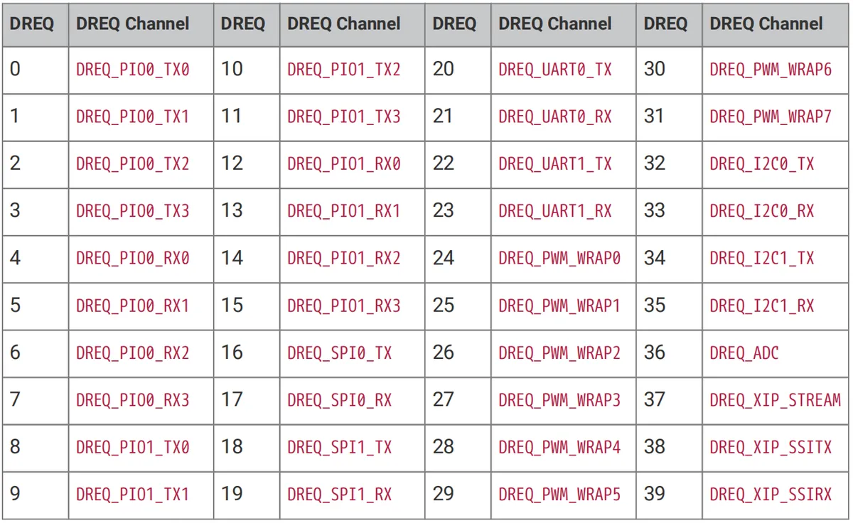
We will configure the DMA request signal according to the number of the serial port peripheral in use.
# 20 is the number of the DREQ_UARTO_TX request signal, 22 is the number of the DREQ_UART1_TX request signal
UART_DREQ = 20 if self.uart_num == 0 else 22
The DMA request signal numbers are shown in the following figure:
Next, we configure the DMA control register and channels:
# Set the DMA control register
ctrl = self.dma.pack_ctrl(enable=True,          # Enable DMA
                          size=0,               # Single transfer size of 8 bits (byte)
                          inc_read=True,        # Read address increments
                          inc_write=False,      # Write address does not increment
                          treq_sel=UART_DREQ    # Set the DMA trigger signal
                          )

# Configure DMA
self.dma.config(read=addressof(buf),     # Source address, i.e. the memory address of the data buffer
                write=self.UART_UARTDR,  # Destination address, i.e. the address of the UART data register
                count=len(buf),          # Number of bytes to transfer
                ctrl=ctrl,               # DMA control register configuration
                trigger=True             # Trigger the DMA transfer immediately
                )
Set the source address of the DMA to the memory address of the data buffer, the destination address to the address of the UART data register, the size of a single data item to 8 bits (i. e., one byte), and enable address increment for reading so as to continuously read the data in buf.
Before initiating DMA data transfer, record the start time of the program; after the DMA transfer is completed or the DMA startup finishes, record the end time, and return the time consumed by this part:
# Record start time
start_time = time.ticks_us()
# Start DMA transfer
self.dma.active(1)

# Blocking mode, wait for the DMA transfer to complete
if blocking == True:
    # Wait for the DMA transfer to complete
    while self.dma.active():
        # Check whether the TXFE bit of the UARTFR register is set
        if not self.is_transmit_fifo_empty():
            # If the TXFE bit is not 1, the FIFO is not empty
            if wait_func is not None:
                # Execute the user-defined callback function
                wait_func()

if callback is not None:
    # Wait for the DMA transfer to finish, then execute the user-defined callback
    callback()

# Record end time
end_time = time.ticks_us()  # Record end time
# Return elapsed time
return time.ticks_diff(end_time, start_time)
Here, we use the is_transmit_fifo_empty method to determine whether the FIFO in UART transmission is empty, and extract the TXFE bit to check the FIFO status, so as to judge the current sending status of serial port data:
def is_transmit_fifo_empty(self) -> bool:
    """
    Check whether the UART transmit FIFO is empty.

    Returns:
        bool: True means empty, False means not empty.
    """

    # Read the value of the UARTFR register
    reg_value = mem32[self.UART_UARTFR]
    # Extract the value of the TXFE bit (bit 7)
    txfe_bit = (reg_value >> 7) & 0x1

    # Determine whether the TXFE bit is 1 (whether the FIFO is empty)
    return txfe_bit == 1
dma_transmit () The complete Sequence Diagram of the method is shown below:
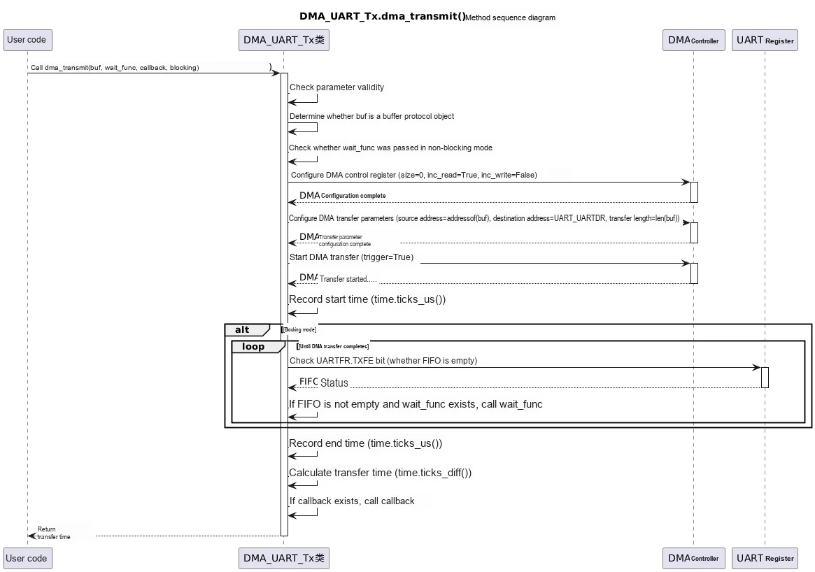
3.2.3 Experimental Routines
The following code can be found in the elegance-devkit v1\Demo\67 DMA_MemoryToPeripheral folder within the resource package we provide.
The main program we tested for the DMA_UART_Tx class is as follows:
# Python env   : MicroPython v1.23.0
# -*- coding: utf-8 -*-
# @Time    : 2024/9/7 11:26 AM
# @Author  : Li Qingshui
# @File    : main.py
# @Description : DMA class experiment, memory-to-peripheral transfer: DMA writes data from memory to the UART

# ======================================== Import Modules =========================================

# Import the math-related module
import math
# Import time-related modules
import time
# Import the custom UART DMA transfer class
from dma_uart_tx import DMA_UART_Tx
# Import hardware-related modules
from machine import UART

# ======================================== Global Variables ============================================

# Data buffer, data to be sent: sine wave data
# Configure sine wave parameters
amplitude = 127     # Amplitude, maximum value of the sine wave (0-255); 127 is half of the unsigned 8-bit range, the peak
offset = 128        # Offset, ensures the waveform stays between 0 and 255
num_samples = 1000  # Number of sine wave sample points
frequency = 1       # Frequency, can be adjusted as needed

# Generate sine wave data and put it into a bytearray
sin_wave = bytearray(num_samples)

for i in range(num_samples):
    # Calculate the angle of the current sample point
    angle = 2 * math.pi * frequency * (i / num_samples)
    # Generate the corresponding sine wave value, scale it up and add the offset to fit the bytearray (0-255) range
    sine_value = int(amplitude * math.sin(angle) + offset)
    # Put the sine value into the bytearray buffer
    sin_wave[i] = sine_value

# Run time of sending data over the serial port with DMA
uart_dma_time = 0
# Run time of sending data over the serial port without DMA
uart_non_dma_time = 0

# ======================================== Functions ============================================

# DMA transfer wait callback function
def uart_dma_tx_wait_func() -> None:
    """
    DMA transfer wait callback function.

    Returns:
        None
    """
    print("wait dma transmit complete")

# DMA transfer complete callback function
def uart_dma_tx_complete_callback() -> None:
    """
    DMA transfer complete callback function.

    Returns:
        None
    """
    print("uart dma transmit complete")

# Append the newline '\r\n' after each element of the bytearray
def add_newline_after_each_byte(buf: bytearray) -> bytearray:
    """
    Append the newline '\r\n' after each element of the bytearray.

    Args:
        buf (bytearray): The input bytearray.

    Returns:
        bytearray: Returns a new bytearray containing '\r\n'.

    Raises:
        TypeError: If the input parameter is not of type bytearray.
    """

    # Check whether the input parameter is a bytearray
    if not isinstance(buf, bytearray):
        raise TypeError("buf must be a bytearray")

    # Create a new bytearray to hold the result
    expanded_buf = bytearray()

    # Iterate over each byte of the input buffer
    for byte in buf:
        # Append the original data byte
        expanded_buf.append(byte)
        # Append the ASCII value of '\r' (13)
        expanded_buf.append(13)
        # Append the ASCII value of '\n' (10)
        expanded_buf.append(10)

    return expanded_buf

# ======================================== Custom Classes ============================================

# ======================================== Initialization ==========================================

# Power-on delay of 3 s
time.sleep(3)
# Print debug information indicating the start of the main program
print("FreakStudio: DMA Memory to Peripheral Test ")

# Instantiate the DMA_UART_Tx class, assuming UART0, baud rate 115200, TX pin 0, RX pin 1
dma_uart = DMA_UART_Tx(uart_num=0, baudrate=115200, tx_pin=0, rx_pin=1)

# Create the serial port object, set the baud rate to 115200
uart = UART(1, 115200)
# Initialize the uart object with a baud rate of 115200, 8 data bits, no parity bit, and 1 stop bit
# Set the receive pin to GPIO5 and the transmit pin to GPIO4
# Set the serial port timeout to 100ms
uart.init(baudrate  = 115200,
          bits      = 8,
          parity    = None,
          stop      = 1,
          tx        = 4,
          rx        = 5,
          timeout   = 100)

# ========================================  Main Program  ===========================================

# Transmit data over the serial port using DMA
# Transmit data in blocking mode
dma_uart.dma_transmit(buf=sin_wave, wait_func=uart_dma_tx_wait_func, callback=uart_dma_tx_complete_callback, blocking=True)
# Transmit data in non-blocking mode and record the run time
uart_dma_time = dma_uart.dma_transmit(buf=sin_wave, blocking=False)

# Transmit data without DMA
# Record the start time
start_time = time.ticks_us()
# Transmit data
uart.write(sin_wave)
# Record the end time
end_time = time.ticks_us()
# Calculate the run time
uart_non_dma_time = time.ticks_diff(end_time, start_time)

# Print debug data to indicate the transfer is complete
print("DMA Finished,run time: %d us" % uart_dma_time)
print("Non-DMA Finished,run time: %d us" % uart_non_dma_time)
Here, we first declare a buffer, and write sine wave data with an amplitude of 127, a DC offset of 128,1000 sampling points and a frequency of 1 Hz into it; then we define uart_dma_time and uart_non_dma_time variables to record the time taken for data transmission with and without DMA. Meanwhile, we set up two callback functions to output debug information during and after the DMA transmission.
The timing sequence of the entire program is shown as follows:
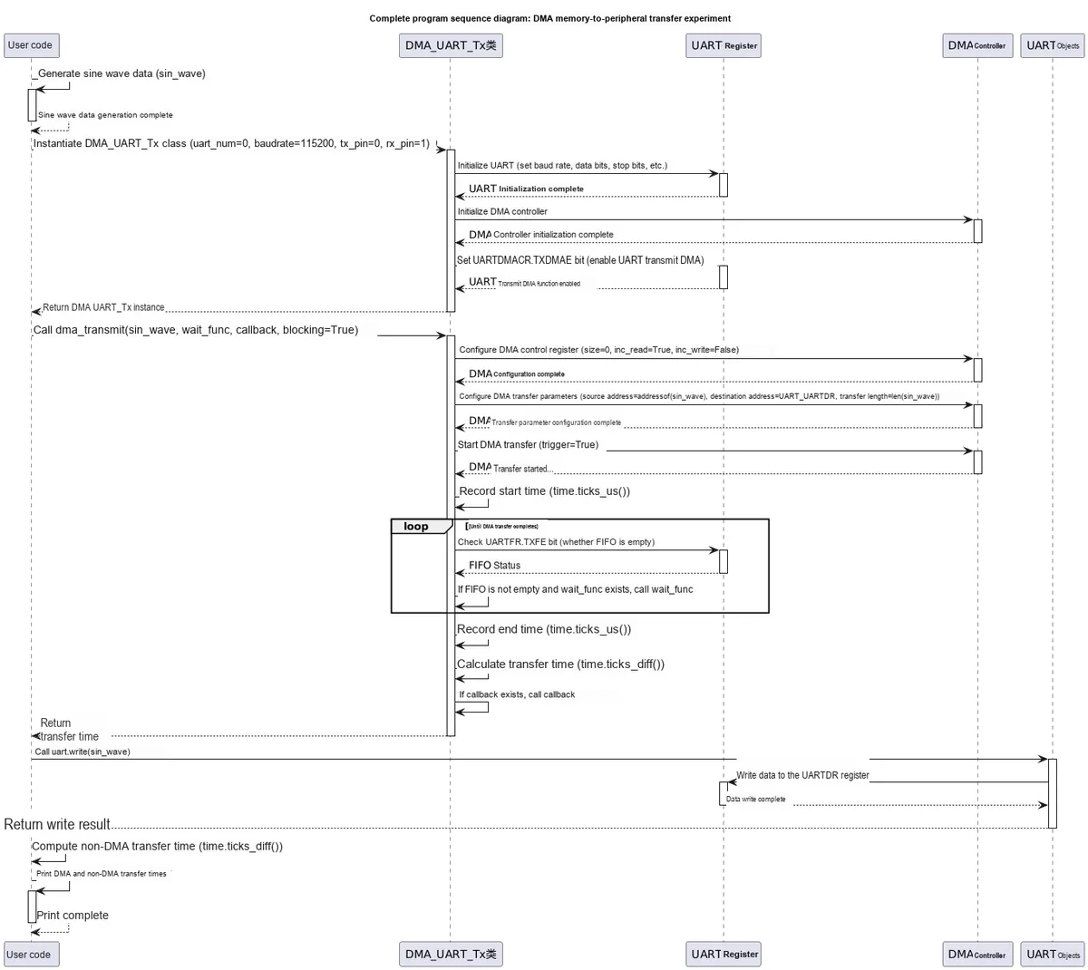
Next, we open the SerialPlot software and select the port corresponding to the serial port of the Raspberry Pi Pico:
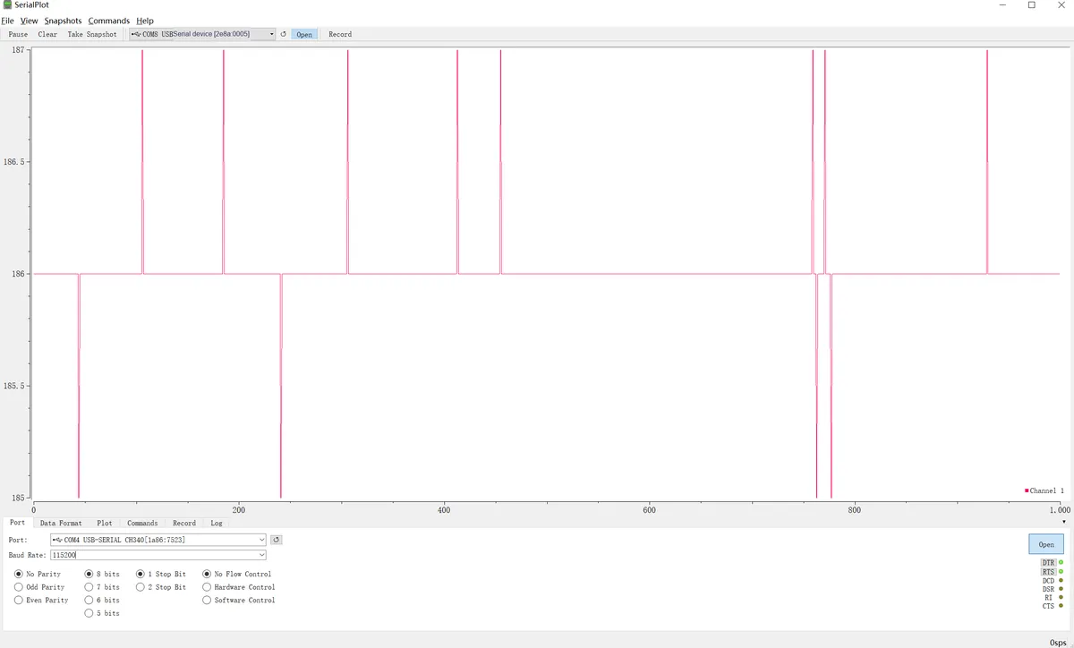
The data format is set as follows:

Burn the code, open the terminal, and the following content will be displayed:
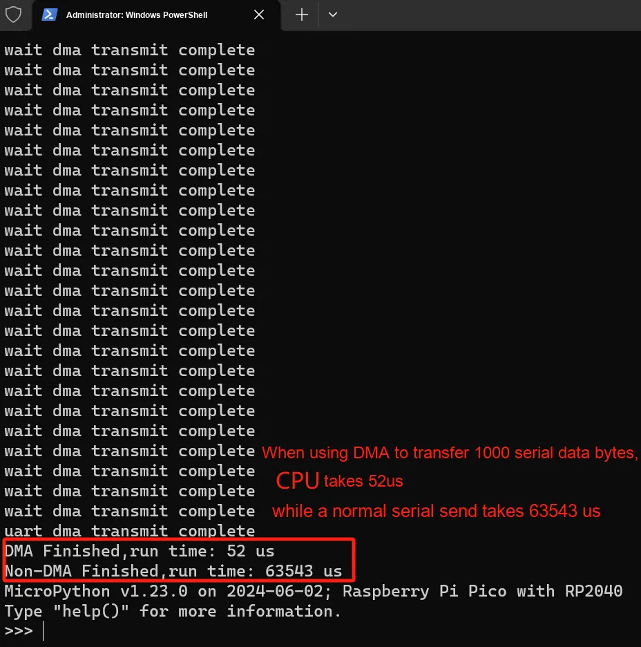
3.2.3 Terminal.mp4 2.1 MB
It can be seen that the CPU occupancy rate of serial port data transmission implemented by DMA is much lower than that of ordinary serial port data transmission. In non-blocking mode, the callback function will be called after the DMA transfer is completed, and no CPU polling is required.
We can also export the CSV file of the data to check whether all the data has been completely received:
data.csv 4 KB
3.2.3 Waveform.mp4 8.8 MB
3.3 DMA Class Implementation for Peripheral-to-Memory Data Transfer
3.3.1 Preparations before the Experiment
In the following experiment, we need to insert the Fengya No. 1 Board - Grove Interface Expansion Board into the Fengya No. 1 Board - Universal Compatible Expansion Board, and meanwhile use a PH2.0-4P cable to connect the AIN0 interface on the Fengya No. 1 Board - Grove Interface Expansion Board and the analog output interface on the GraftSense - Slide Potentiometer Module:
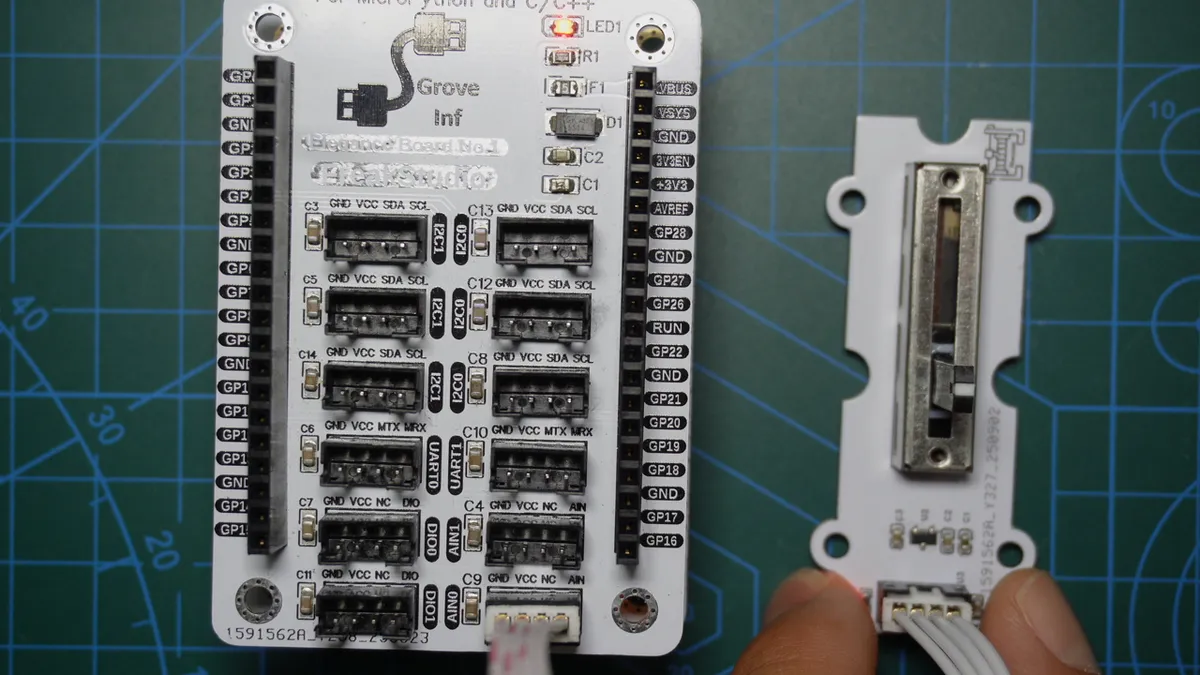
In addition, we first need to connect the MiniUSB data cable to the serial port on Fengya No. 1 Board - Universal Compatible Expansion Board. Here, GP0 and GP1 are the default pins of the hardware serial port UART0 of the Raspberry Pi Pico:
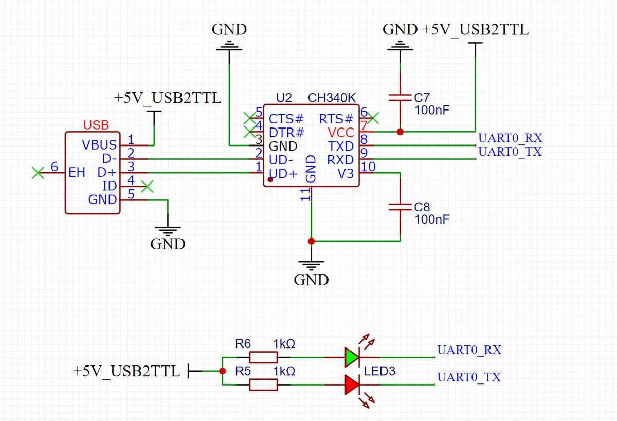
The physical image after insertion is as follows:
The pin connections are shown in the following table:
| Module / Device | Pin / Interface | Connection target | Target pin / Interface |
| Fengya No. 1 board - Grove interface expansion board | AIN0 interface | GraftSense - Slide Rheostat Module | Analog output interface |
| Fengya No. 1 board - Grove interface expansion board | AIN0 internal connection | Raspberry Pi Pico (core of the Fengya No. 1 board) | GP26 (ADC0) |
| Raspberry Pi Pico (core of the Fengya No. 1 board) | GP0 (UART0_TX) | Fengya No. 1 board - Universal compatible expansion board | Serial port TX pin |
| Raspberry Pi Pico (core of the Fengya No. 1 board) | GP1 (UART0_RX) | Fengya No. 1 board - Universal compatible expansion board | Serial port RX pin |
| Fengya No. 1 board - Universal compatible expansion board | Serial port interface | MiniUSB cable | USB male end |
| Fengya No. 1 board - Grove interface expansion board | - | Fengya No. 1 board - Universal compatible expansion board | - |
3.3.2 Implementation of Custom Analog-to-Digital Conversion DMA Transfer Class
Here, we define a DMA_ADC_Transfer class, which is used to implement the transmission of ADC conversion data from the FIFO register to memory via DMA on the Raspberry Pi Pico.
The sample code is as follows:
# Python env   : MicroPython v1.23.0
# -*- coding: utf-8 -*-
# @Time    : 2024/9/8 11:15 PM
# @Author  : Li Qingshui
# @File    : dma_adc_trans.py.py
# @Description : Custom DMA transfer class for ADC data acquisition

# ======================================== Import Modules =========================================

# Import hardware-related modules
from machine import ADC
# Import the addressof function, used to get the memory address of data
from uctypes import addressof
# Import DMA-related modules
from rp2 import DMA
# Import the module for reading and writing 32-bit memory
from machine import mem32

# ======================================== Global Variables ============================================

# ======================================== Functions ============================================

# ======================================== Custom Classes ============================================

# Custom ADC class that transfers data via DMA
class DMA_ADC_Transfer:
    """
    DMA_ADC_Transfer class, used for efficient ADC data transfer via DMA.
    This class encapsulates ADC configuration, DMA transfer, FIFO control and other functions, enabling high-speed sampling into a user-provided buffer.

    This class supports free-running sampling mode and a configurable ADC sample rate, and provides both blocking and non-blocking modes for DMA transfer.

    Attributes:
        buf (bytearray): Buffer used to store ADC sample data.
        sample_rate (int): Desired ADC sample rate (Hz).
        adc (ADC): ADC instance object, used for analog-to-digital conversion.
        dma (DMA): DMA controller instance object.

    Constants:
        DREQ_ADC (int): DMA trigger signal ID of the ADC.
        ADC_BASE (int): Base address of the ADC FIFO registers.
        CS_REG (int): Address offset of the control register (CS).
        RESULT_REG (int): Address offset of the result register (RESULT).
        FCS_REG (int): Address offset of the FIFO control register (FCS).
        DIV_REG (int): Address offset of the sample divider register (DIV).
        FIFO_REG (int): Address offset of the FIFO data register (FIFO).
        FIFO_THRESH (int): Threshold at which the ADC FIFO triggers a DMA transfer.
        ADC_CLOCK_FREQ (int): ADC clock frequency, assumed to be 48MHz.

    Methods:
        __init__(self, buf: bytearray, sample_rate: int = 1000, adc_id: int = 0):
            Initialize an instance of the DMA_ADC_Transfer class and configure the ADC and DMA.

        configure_adc_fifo(self) -> None:
            Configure the ADC FIFO so that it can work with DMA for data transfer.

        start_adc_continuous(self) -> None:
            Start the ADC free-running sampling mode so that it keeps acquiring data continuously.

        configure_adc_sample_rate(self, sample_rate: int) -> None:
            Configure the ADC sample rate and set the corresponding clock divider.

        stop_dma_adc_fifo(self) -> None:
            Stop the DMA transfer and ADC sampling, ensuring the sampling process ends safely.

        start_dma_transfer(self, wait_func: callable = None, complete_callback: callable = None, blocking: bool = True) -> None:
            Start the DMA transfer, with the option to block until it completes or to specify a transfer-complete callback.

        close(self) -> None:
            Shut down the DMA transfer and release the ADC resources.
    """

    # DMA trigger signal of the ADC
    DREQ_ADC = 36

    # Base address of the ADC FIFO registers
    ADC_BASE = 0x4004C000
    # CS register offset is 0x00
    CS_REG = ADC_BASE + 0x00
    # RESULT register offset is 0x04
    RESULT_REG = ADC_BASE + 0x04
    # FIFO control register offset is 0x08
    FCS_REG = ADC_BASE + 0x08
    # DIV register offset is 0x10
    DIV_REG = ADC_BASE + 0x10
    # FIFO register offset is 0x0C
    FIFO_REG = ADC_BASE + 0x0C

    # FIFO threshold of the ADC
    FIFO_THRESH = 1

    # ADC clock frequency, assumed to be 48MHz
    ADC_CLOCK_FREQ = 48_000_000

    def __init__(self, buf: bytearray, sample_rate: int = 1000, adc_id: int = 0) -> None:
        """
        Initialize an instance of the DMA_ADC_Transfer class.

        Args:
            buf (bytearray): Data buffer passed in by the user.
            sample_rate (int): Desired sample rate (Hz), default is 1000.
            adc_id (int): ADC ID number (0, 1 or 2), default is 0.

        Raises:
            TypeError: If buf is not of type bytearray.
            ValueError: If adc_id is not 0, 1 or 2, or the sample rate is out of range.
        """
        # Check whether buf is of type bytearray
        if not isinstance(buf, bytearray):
            raise TypeError("buf must be bytearray")

        # Check whether adc_id is 0, 1 or 2
        if adc_id not in (0, 1, 2):
            raise ValueError("adc_id must be 0, 1 or 2")

        # Buffer: the buffer passed in by the user
        self.buf = buf
        # Sample rate
        self.sample_rate = sample_rate
        # Create the ADC object
        self.adc = ADC(adc_id)
        # Create the DMA channel object
        self.dma = DMA()
        # Configure the ADC FIFO
        self.configure_adc_fifo()
        # Configure the ADC sample rate
        self.configure_adc_sample_rate(self.sample_rate)
        # Start free-running sampling mode
        self.start_adc_continuous()

    def configure_adc_fifo(self) -> None:
        """
        Configure the ADC FIFO to work with the DMA controller.
        By default the FIFO is right-shifted by 4 bits, so the ADC data is 8 bits wide with a maximum value of 255.

        Returns:
            None
        """
        # Enable the FIFO (FCS.EN), enable the DMA request signal (FCS.DREQ_EN), set the FIFO right shift (FCS.SHIFT)
        fcs_value = mem32[DMA_ADC_Transfer.FCS_REG]
        mem32[DMA_ADC_Transfer.FCS_REG] = fcs_value | (1 << 0) | (1 << 3) | (1 << 1)
        # Set the FIFO threshold (FCS.THRESH)
        mem32[DMA_ADC_Transfer.FCS_REG] |= (DMA_ADC_Transfer.FIFO_THRESH << 24)

    def start_adc_continuous(self) -> None:
        """
        Start free-running sampling mode by enabling the START_MANY bit.
        The ADC will automatically start new conversions at a fixed interval.

        Returns:
            None
        """
        # Read the current value of the CS register
        cs_value = mem32[DMA_ADC_Transfer.CS_REG]
        # Set the START_MANY bit to 1
        mem32[DMA_ADC_Transfer.CS_REG] = cs_value | (1 << 3)

    def configure_adc_sample_rate(self, sample_rate: int) -> None:
        """
        Configure the ADC sample rate.

        Args:
            sample_rate (int): Desired sample rate (Hz).

        Returns:
            None

        Raises:
            ValueError: If the sample rate is out of range.
        """
        # Make sure the sample rate is within a reasonable range
        if sample_rate <= 0 or sample_rate > 48_000_000:
            raise ValueError("sample rate out of range")

        # DMA is only fully effective at sample rates above 1000Hz
        # At sample rates below 1000Hz, a normal software timer is enough for sampling
        if sample_rate < 1000:
            raise ValueError("sample rate too low")

        # Calculate the divider value
        total_period = 48_000_000 / sample_rate
        int_part = int(total_period) - 1
        frac_part = int((total_period - int_part - 1) * 256)

        # Write the sampling period to the DIV register
        mem32[DMA_ADC_Transfer.DIV_REG] = (int_part << 8) | frac_part

    def stop_dma_adc_fifo(self) -> None:
        """
        Stop the DMA transfer and ADC conversion.

        Returns:
            None
        """
        # Clear the START_MANY bit in the CS register to stop ADC conversion
        # Read the CS register
        adc_cs_value = mem32[DMA_ADC_Transfer.CS_REG]
        # Clear the START_MANY bit
        adc_cs_value &= ~(1 << 3)
        # Write back to the CS register
        mem32[DMA_ADC_Transfer.CS_REG] = adc_cs_value

        # Poll the READY bit to make sure the last conversion has completed
        while not ((mem32[DMA_ADC_Transfer.CS_REG]>>8) & 0x1):
            pass

    def start_dma_transfer(self, wait_func: callable = None, complete_callback: callable = None, blocking: bool = True) -> None:
        """
        Start the DMA transfer.

        Args:
            wait_func (callable): Function called while waiting for the DMA transfer to complete, optional.
            complete_callback (callable): Callback function for DMA transfer completion, optional.
            blocking (bool): Whether to block until the transfer completes, default is True.

        Returns:
            None

        Raises:
            ValueError: If wait_func is passed in non-blocking mode.
        """

        # If non-blocking mode is selected, wait_func should not be passed in
        if blocking == False and wait_func is not None:
            raise ValueError("wait_func must be None when blocking is False")

        # If complete_callback is not None, run the user-defined function
        if complete_callback is not None:
            # Transfer-complete interrupt callback function
            self.dma.irq(handler=complete_callback, hard=True)

        # Set the DMA control register
        ctrl = self.dma.pack_ctrl(
            enable=True,                         # Enable DMA
            size=0,                              # Single transfer size is 8 bits, byte-by-byte transfer
            inc_read=False,                      # Read address does not increment
            inc_write=True,                      # Write address increments
            treq_sel=DMA_ADC_Transfer.DREQ_ADC,  # Select the DMA trigger source
            irq_quiet = False                    # Generate an interrupt at the end of each transfer
        )

        # Configure the DMA channel
        self.dma.config(
            read=self.FIFO_REG,         # Source address, i.e. the address of the ADC peripheral FIFO register
            write=addressof(self.buf),  # Destination address, i.e. the address of the data buffer
            count=len(self.buf),        # Total number of data transfers
            ctrl=ctrl,                  # DMA control register configuration
            trigger=False               # Do not trigger the DMA transfer immediately
        )

        # Start DMA transfer
        self.dma.active(1)

        # Blocking mode, wait for the DMA transfer to complete
        if blocking == True:
            # Wait for the DMA to finish
            while self.dma.active():
                # If wait_func is not None, run the user-defined function
                if wait_func is not None:
                    # Run the user-defined function
                    wait_func()
        else:
            # Non-blocking mode, do not wait for the DMA to finish
            return

    def close(self) -> None:
        """
        Close the DMA channel and stop the ADC.

        Returns:
            None
        """
        # Release the DMA channel
        self.dma.close()
        # Stop ADC conversion
        self.stop_dma_adc_fifo()

# ======================================== Initialization ==========================================

# ========================================  Main Program  ===========================================
Here, the process by which the DMA controller acquires ADC acquisition data by reading the ADC sample FIFO register is controlled by the ADC_DREQ system data request signal, and the configuration process is as follows:
- Enable FIFO (
FCS.EN): The FIFO must be enabled to allow ADC conversion results to be written into it. By default, the FIFO is disabled to prevent accidental filling of the FIFO during single-shot conversion operations.
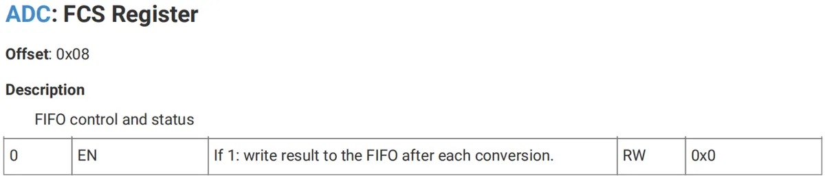
- Enable ADC DMA request (
FCS.DREQ_EN): The ADC DMA request signal DREQ must be enabled so that the DMA can read data from the FIFO according to the request signal of the ADC
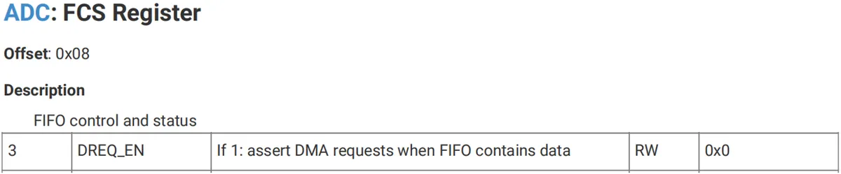
- Select the DREQ_ADC data request signal for the DMA channel: The DMA channel in use must select the DREQ_ADC data request signal to ensure that the DMA can operate in synchronization with the ADC's data request signal.
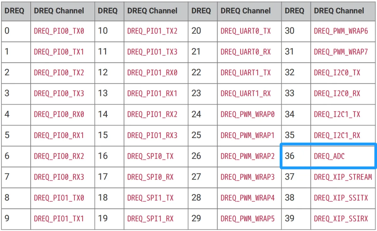
- Set the DREQ assertion threshold (
FCS.THRESH): The DREQ assertion threshold should be set to 1, so that the DMA starts transmission as soon as there is one sample in the FIFO. Note that this is also the threshold for IRQ assertion, so in non-DMA usage scenarios, a higher value may be required to reduce the interrupt frequency.
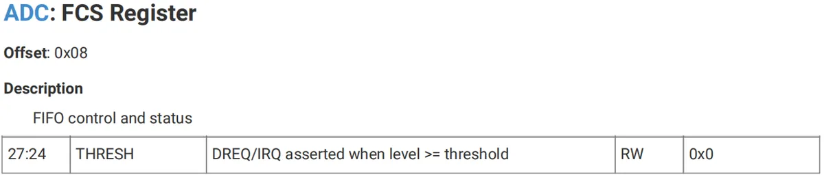
- Configuration for 8-bit DMA transfer (
FCS.SHIFT): If the DMA transfer size is set to 8 bits (i. e., data is transferred to a byte array in memory), FCS.SHIFT must be enabled to pre-shift the FIFO samples to the right to form one byte of data
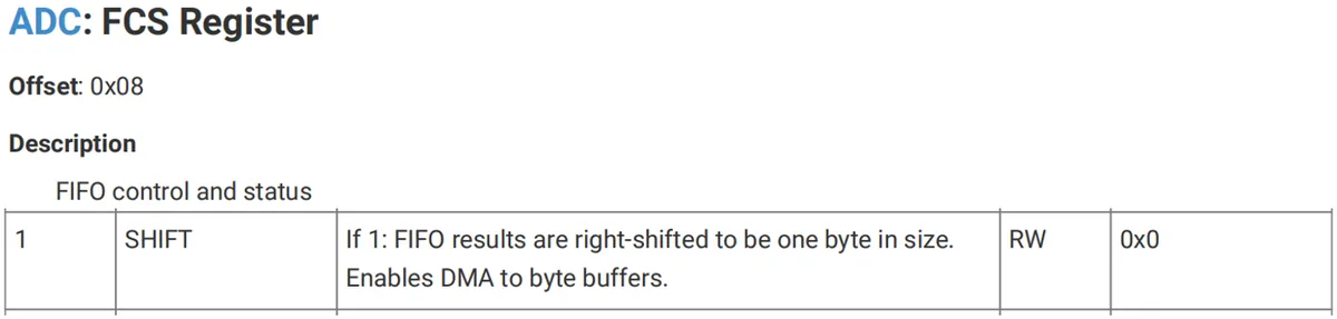
- Configure ADC sampling rate (
DIV): Before starting the ADC, the ADC sampling rate should be configured properly in advance
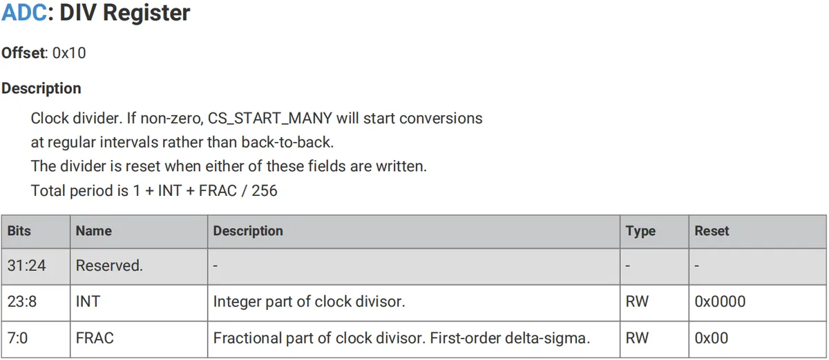
- Set the free sampling mode (
CS.START_MANY): which means continuously performing ADC sampling
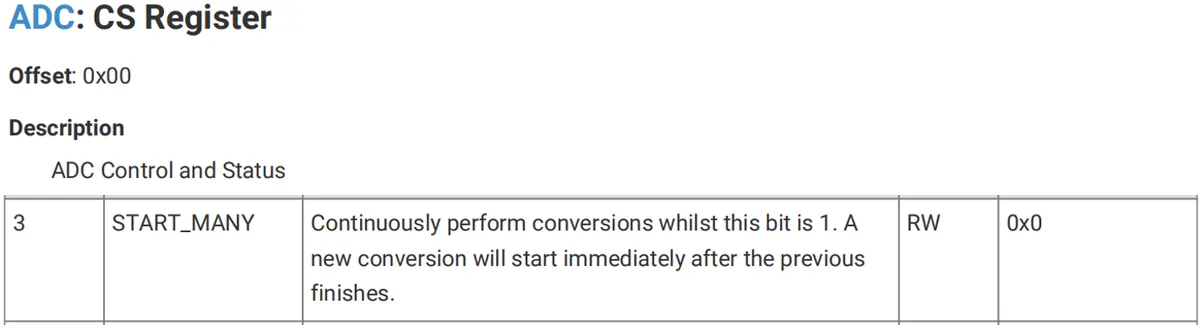
- Start the DMA channel to initiate data transmission; after the DMA completes one round of data transfer, the ADC can be stopped or a new DMA transfer can be started immediately.
- Clear the
CS.START_MANYdata bit to stop the ADC, after which the software shall perform polling on theCS.READYdata bit to ensure that the last conversion has been completed, and clear any excess sampling data in the FIFO
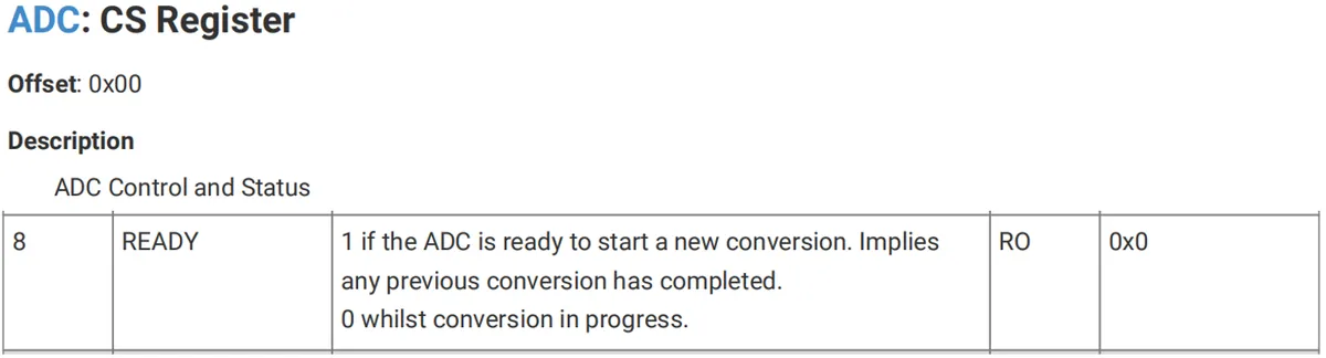
In the custom DMA_ADC_Transfer class, the following methods are available:
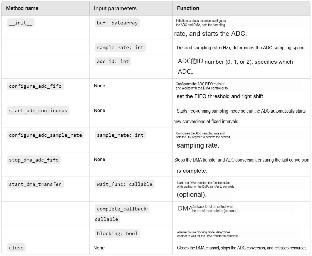
In the initialization method, we complete the relevant configuration of the ADC peripheral for DMA transfer:
# Custom ADC class that transfers data via DMA
class DMA_ADC_Transfer:
    """
    DMA_ADC_Transfer class, used for efficient ADC data transfer via DMA.
    This class encapsulates ADC configuration, DMA transfer, FIFO control and other functions, enabling high-speed sampling into a user-provided buffer.

    This class supports free-running sampling mode and a configurable ADC sample rate, and provides both blocking and non-blocking modes for DMA transfer.

    Attributes:
        buf (bytearray): Buffer used to store ADC sample data.
        sample_rate (int): Desired ADC sample rate (Hz).
        adc (ADC): ADC instance object, used for analog-to-digital conversion.
        dma (DMA): DMA controller instance object.

    Constants:
        DREQ_ADC (int): DMA trigger signal ID of the ADC.
        ADC_BASE (int): Base address of the ADC FIFO registers.
        CS_REG (int): Address offset of the control register (CS).
        RESULT_REG (int): Address offset of the result register (RESULT).
        FCS_REG (int): Address offset of the FIFO control register (FCS).
        DIV_REG (int): Address offset of the sample divider register (DIV).
        FIFO_REG (int): Address offset of the FIFO data register (FIFO).
        FIFO_THRESH (int): Threshold at which the ADC FIFO triggers a DMA transfer.
        ADC_CLOCK_FREQ (int): ADC clock frequency, assumed to be 48MHz.

    Methods:
        __init__(self, buf: bytearray, sample_rate: int = 1000, adc_id: int = 0):
            Initialize an instance of the DMA_ADC_Transfer class and configure the ADC and DMA.

        configure_adc_fifo(self) -> None:
            Configure the ADC FIFO so that it can work with DMA for data transfer.

        start_adc_continuous(self) -> None:
            Start the ADC free-running sampling mode so that it keeps acquiring data continuously.

        configure_adc_sample_rate(self, sample_rate: int) -> None:
            Configure the ADC sample rate and set the corresponding clock divider.

        stop_dma_adc_fifo(self) -> None:
            Stop the DMA transfer and ADC sampling, ensuring the sampling process ends safely.

        start_dma_transfer(self, wait_func: callable = None, complete_callback: callable = None, blocking: bool = True) -> None:
            Start the DMA transfer, with the option to block until it completes or to specify a transfer-complete callback.

        close(self) -> None:
            Shut down the DMA transfer and release the ADC resources.
    """

    # DMA trigger signal of the ADC
    DREQ_ADC = 36

    # Base address of the ADC FIFO registers
    ADC_BASE = 0x4004C000
    # CS register offset is 0x00
    CS_REG = ADC_BASE + 0x00
    # RESULT register offset is 0x04
    RESULT_REG = ADC_BASE + 0x04
    # FIFO control register offset is 0x08
    FCS_REG = ADC_BASE + 0x08
    # DIV register offset is 0x10
    DIV_REG = ADC_BASE + 0x10
    # FIFO register offset is 0x0C
    FIFO_REG = ADC_BASE + 0x0C

    # FIFO threshold of the ADC
    FIFO_THRESH = 1

    # ADC clock frequency, assumed to be 48MHz
    ADC_CLOCK_FREQ = 48_000_000

    def __init__(self, buf: bytearray, sample_rate: int = 1000, adc_id: int = 0) -> None:
        """
        Initialize an instance of the DMA_ADC_Transfer class.

        Args:
            buf (bytearray): Data buffer passed in by the user.
            sample_rate (int): Desired sample rate (Hz), default is 1000.
            adc_id (int): ADC ID number (0, 1 or 2), default is 0.

        Raises:
            TypeError: If buf is not of type bytearray.
            ValueError: If adc_id is not 0, 1 or 2, or the sample rate is out of range.
        """
        # Check whether buf is of type bytearray
        if not isinstance(buf, bytearray):
            raise TypeError("buf must be bytearray")

        # Check whether adc_id is 0, 1 or 2
        if adc_id not in (0, 1, 2):
            raise ValueError("adc_id must be 0, 1 or 2")

        # Buffer: the buffer passed in by the user
        self.buf = buf
        # Sample rate
        self.sample_rate = sample_rate
        # Create the ADC object
        self.adc = ADC(adc_id)
        # Create the DMA channel object
        self.dma = DMA()
        # Configure the ADC FIFO
        self.configure_adc_fifo()
        # Configure the ADC sample rate
        self.configure_adc_sample_rate(self.sample_rate)
        # Start free-running sampling mode
        self.start_adc_continuous()
In the initialization method, we mainly perform the following tasks: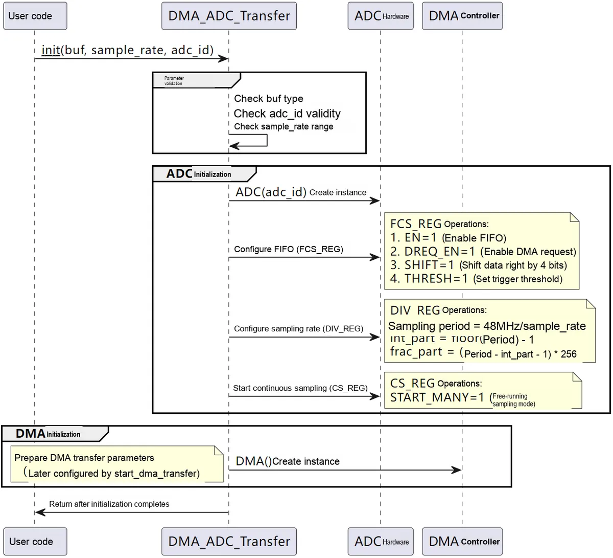
- Parameter check: Check
bufwhether it is of typebytearray, check whetheradc_idis valid (0/1/2), check whethersample_rateis within the valid range (>1000Hz); - Configure the FIFO and sampling rate of the ADC, and start the free sampling mode of the ADC: this is mainly implemented via the
configure_adc_fifomethod, theconfigure_adc_sample_ratemethod, thestart_adc_continuousmethod, and thestop_dma_adc_fifomethod.
Here, the configure_adc_fifo method, the configure_adc_sample_rate method, the start_adc_continuous method, and the stop_dma_adc_fifo method are mainly implemented by reading and writing the corresponding registers, and they primarily perform the following tasks:
configure_adc_fifo ()Method: Configure the FIFO (First-In First-Out queue) of the ADC to cooperate with the DMA controller to implement automatic data transfer.- Enable FIFO:
- Set the
ENbit (bit 0) ofFCS_REGto 1 to enable the ADC FIFO. - Set the
DREQ_ENbit (bit 3) to 1 to enable the FIFO to trigger DMA requests. - Set the
SHIFTbit (bit 1) to 1 to right-shift the ADC data by 4 bits (by default, the 12-bit ADC data becomes 8 bits after right-shifting, which facilitates DMA transmission).
- Set the
- Set FIFO threshold:
THRESH(bits 24-31) sets the threshold for the FIFO to trigger DMA (defaultFIFO_THRESH = 1, meaning DMA is triggered when there is 1 piece of data in the FIFO).
- Enable FIFO:
configure_adc_sample_rate ()Method: Configure the ADC sampling rate, and achieve the target sampling rate by adjusting the clock divider (DIV_REG).- Calculate the frequency division value:
- The ADC clock frequency is fixed at 48MHz.
- Sampling period =
48_000_000 / sample_rate. - Frequency division value =
sampling period - 1, and is split into an integer part (int_part) and a fractional part (frac_part).
- Write to
DIV_REG:int_partwrites to the upper 8 bits (bits 8-15).frac_partis written to the lower 8 bits (bits 0-7).
- Calculate the frequency division value:
start_adc_continuous ()Method: Start the ADC's free-running sampling mode to enable continuous sampling of the ADC.- In the
CS_REG(Control Status Register), whenSTART_MANY(bit 3) is set to 1, the ADC enters the free sampling mode. - The ADC automatically performs continuous conversion at the set sampling rate without requiring software intervention.
- In the
stop_dma_adc_fifo ()Method: Stops DMA transfer and ADC sampling to ensure safe shutdown of the ADC and DMA.- Stop ADC sampling:
- Clear the
START_MANYbit (bit 3) ofCS_REG, and the ADC will stop sampling. - polling
READYbit (bit 8) to ensure that the last conversion is completed.
- Clear the
- DMA Auto Stop:
- Since DMA relies on the FIFO trigger of the ADC, the DMA will also stop automatically after the ADC stops.
- Stop ADC sampling:
The method for implementing data transmission via DMA is start_dma_transfer, and the sample code is as follows:
def start_dma_transfer(self, wait_func = None, complete_callback = None, blocking = True):
    """
    Start the DMA transfer
    :param wait_func: Function called while waiting for the DMA transfer to complete
    :param complete_callback: Callback function for DMA transfer completion
    :return: None
    """

    # If non-blocking mode is selected, wait_func should not be passed in
    if blocking == False and wait_func is not None:
        raise ValueError("wait_func must be None when blocking is False")

    # If complete_callback is not None, run the user-defined function
    if complete_callback is not None:
        # Transfer-complete interrupt callback function
        self.dma.irq(handler=complete_callback, hard=True)

    # Set the DMA control register
    ctrl = self.dma.pack_ctrl(
        enable=True,                         # Enable DMA
        size=0,                              # Single transfer size is 8 bits, byte-by-byte transfer
        inc_read=False,                      # Read address does not increment
        inc_write=True,                      # Write address increments
        treq_sel=DMA_ADC_Transfer.DREQ_ADC,  # Select the DMA trigger source
        irq_quiet = False                    # Generate an interrupt at the end of each transfer
    )

    # Configure the DMA channel
    self.dma.config(
        read=self.FIFO_REG,         # Source address, i.e. the address of the ADC peripheral FIFO register
        write=addressof(self.buf),  # Destination address, i.e. the address of the data buffer
        count=len(self.buf),        # Total number of data transfers
        ctrl=ctrl,                  # DMA control register configuration
        trigger=False               # Do not trigger the DMA transfer immediately
    )

    # Start DMA transfer
    self.dma.active(1)

    # Blocking mode, wait for the DMA transfer to complete
    if blocking == True:
        # Wait for the DMA to finish
        while self.dma.active():
            # If wait_func is not None, run the user-defined function
            if wait_func is not None:
                # Run the user-defined function
                wait_func()
    else:
        # Non-blocking mode, do not wait for the DMA to finish
        return
After mainly completing the configuration of the DMA control register and channels, it enables DMA transmission and executes the callback function input by the user after the transmission is completed: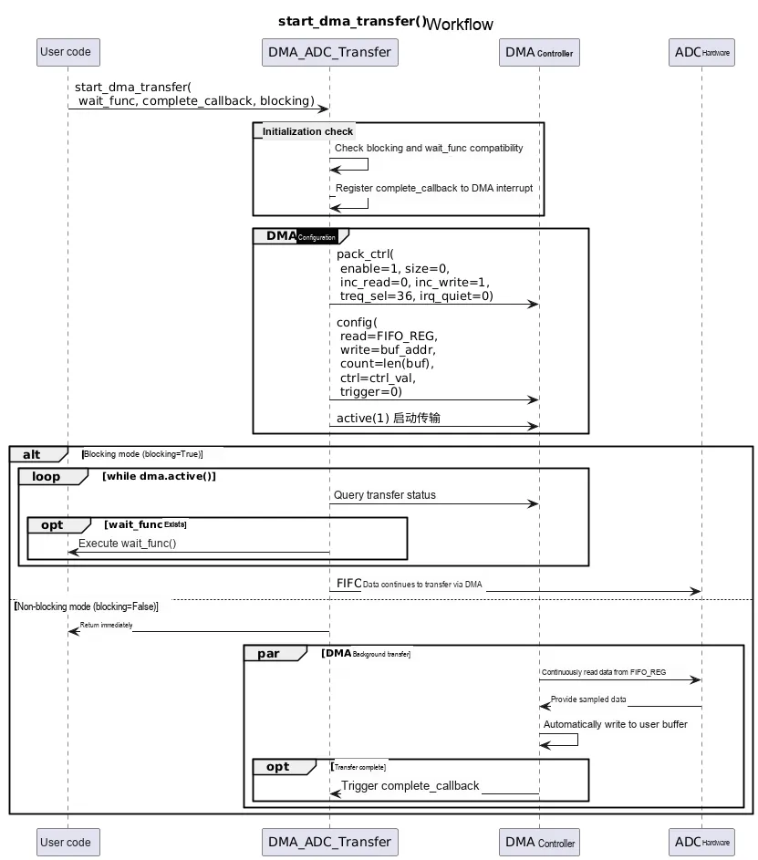
- First, perform parameter check:), and if
wait_funcis illegally passed in non-blocking mode (blocking= False), and ifcomplete_callbackis passed, register the DMA interrupt callback. - Configure the DMA control register: enable the DMA channel, set to transmit 8-bit data in single transfer mode, fix the ADC FIFO address, enable auto-increment for the buffer address, use the ADC FIFO as the trigger source, and configure to generate an interrupt upon completion of each transfer.
- Set transmission parameters: set the DMA source address to
FIFO_REG(the address of the ADC data register0x4004C00C), set the write address toaddressof (buf)(the physical address of the user buffer), set the total transmission count to the buffer length, and trigger the transmission manually. - Determine whether it is in blocking mode: If it is in blocking mode and
wait_funcis passed in, then while the DMA transfer is not yet completed, executewait_func, the user-defined callback function, in a loop.
3.3.3 Experimental Routines
The following code can be found in the elegance-devkit v1\Demo\68 DMA_PeripheralToMemory folder within the resource package we provide.
Test DMA_ADC_Transfer the code of the class is as follows:
# Python env   : MicroPython v1.23.0
# -*- coding: utf-8 -*-
# @Time    : 2024/9/8 11:04 AM
# @Author  : Li Qingshui
# @File    : main.py
# @Description : DMA class experiment, peripheral-to-memory transfer, DMA transfers data from the ADC peripheral FIFO to memory

# ======================================== Import Modules =========================================

# Import time-related modules
import time
# Import the custom ADC DMA class
from dma_adc_trans import DMA_ADC_Transfer
# Import the custom UART DMA transfer class
from dma_uart_tx import DMA_UART_Tx
# Import MicroPython-related modules
import micropython
# Import hardware-related modules
from machine import Timer

# ======================================== Global Variables ============================================

# Data buffer: 256 elements, each 8 bits (1 byte)
buf1 = bytearray(256)
# Second ADC data buffer
buf2 = bytearray(256)

# Run time of sending data over the serial port with DMA
uart_dma_time = 0
# Run time of the ADC data transfer using DMA
adc_dma_time = 0

# Flags indicating that the ADC DMA transfer of DMA_ADC_Transfer instance 1 and the UART DMA transfer have completed
dma_1_adc_complete_flag = False
# Flags indicating that the ADC DMA transfer of DMA_ADC_Transfer instance 2 and the UART DMA transfer have completed
dma_2_adc_complete_flag = False

# ======================================== Functions ============================================

def adc_wait_dma_complete() -> None:
    """
    Function called when the DMA transfer of the data in the ADC FIFO completes.

    Args:
        None

    Returns:
        None
    """

    # Print debug information
    print("DMA-ADC transmitting ADC data")

def adc_dma_complete_callback(d: object) -> None:
    """
    Called when the DMA transfer of ADC FIFO data is complete.

    Args:
        d (object): The DMA channel instance in use.

    Returns:
        None
    """

    # Print debug information
    print("DMA-ADC transfer complete")

def uart_dma_trans_buf1_isr(d: object) -> None:
    """
    Interrupt function called when the DMA transfer of ADC FIFO data is complete; schedules the corresponding callback function to run as soon as possible.

    Args:
        d (object): The DMA channel instance in use.

    Returns:
        None
    """

    # Schedule the callback function to run later
    micropython.schedule(uart_dma_trans_buf1, d)

def uart_dma_trans_buf1(d: object) -> None:
    """
    DMA transfer of serial port data, with buf1 as the read address.

    Args:
        d (object): The DMA channel instance in use.

    Returns:
        None
    """

    # Declare global variables
    global dma_uart, buf1, dma_1_adc_complete_flag

    # Wait until the ADC DMA transfer has completely finished
    while d.active():
        pass

    # Use DMA to transfer serial port data, with buf1 as the read address
    dma_uart.dma_transmit(buf=buf1, blocking=False)
    # Set the flag
    dma_1_adc_complete_flag = True

def uart_dma_trans_buf2_isr(d: object) -> None:
    """
    Interrupt function called when the DMA transfer of ADC FIFO data is complete; schedules the corresponding callback function to run as soon as possible.

    Args:
        d (object): The DMA channel instance in use.

    Returns:
        None
    """

    # Schedule the callback function to run later
    micropython.schedule(uart_dma_trans_buf2, d)

def uart_dma_trans_buf2(d: object) -> None:
    """
    DMA transfer of serial port data, with buf2 as the read address.

    Args:
        d (object): The DMA channel instance in use.

    Returns:
        None
    """

    # Declare global variables
    global dma_uart, buf2, dma_2_adc_complete_flag

    # Wait until the ADC DMA transfer has completely finished
    while d.active():
        pass

    # Use DMA to transfer serial port data, with buf2 as the read address
    dma_uart.dma_transmit(buf=buf2, blocking=False)
    # Set the flag
    dma_2_adc_complete_flag = True

# def dma_timer_check(timer: Timer) -> None:
#     """
#     Timer interrupt function for checking the DMA data transfer; checks whether the DMA transfer is complete,
#     and if so, starts the DMA transfer of the other buffer.
#
#     Args:
#         timer (machine.Timer): The timer instance that triggered the interrupt.
#
#     Returns:
#         None
#     """
#     global dma_adc_1, dma_adc_2, dma_1_adc_complete_flag, dma_2_adc_complete_flag
#
#     if dma_2_adc_complete_flag:
#         dma_adc_1.start_dma_transfer(blocking=False, complete_callback=uart_dma_trans_buf1_isr)
#         dma_2_adc_complete_flag = False
#
#     if dma_1_adc_complete_flag:
#         dma_adc_2.start_dma_transfer(blocking=False, complete_callback=uart_dma_trans_buf2_isr)
#         dma_1_adc_complete_flag = False

# ======================================== Custom Classes ============================================

# ======================================== Initialization ==========================================

# Power-on delay of 3 s
time.sleep(3)
# Print debug information indicating the start of the main program
print("FreakStudio: DMA Peripheral to Memory Test")

# Initialize a DMA_ADC_Transfer class instance and pass in the data buffer
dma_adc = DMA_ADC_Transfer(buf = buf1, sample_rate = 2000, adc_id = 0)
# Instantiate the DMA_UART_Tx class, assuming UART0, baud rate 115200, TX pin 0, RX pin 1
dma_uart = DMA_UART_Tx(uart_num=0, baudrate=115200, tx_pin=0, rx_pin=1)

# ========================================  Main Program  ===========================================

# Record start time
start_time = time.ticks_us()
# Start the DMA transfer: blocking mode; debug information is printed while the transfer is incomplete, and also after the transfer completes
dma_adc.start_dma_transfer(wait_func = adc_wait_dma_complete,
                           complete_callback = adc_dma_complete_callback,
                           blocking = True)
# Record end time
end_time = time.ticks_us()

# Close the DMA channel and stop the ADC
dma_adc.close()

# Calculate the DMA data transfer time
adc_dma_time = time.ticks_diff(end_time, start_time) / 1000

# Print the DMA data transfer time
print("DMA run time: {:.2f} ms".format(adc_dma_time))

# Print debug information
print("FreakStudio: Start DMA UART transmit")

# Transmit data over the serial port using DMA
# Transfer data using blocking mode and record the run time
uart_dma_time = dma_uart.dma_transmit(buf=buf1,blocking=True) / 1000

# Print debug data to indicate the transfer is complete
print("DMA UART Finished,run time: {:.2f} ms".format(uart_dma_time))

# Initialize DMA_ADC_Transfer class instance 1 and pass in data buffer buf1
dma_adc_1 = DMA_ADC_Transfer(buf=buf1, sample_rate=2000, adc_id=0)
# Initialize DMA_ADC_Transfer class instance 2 and pass in data buffer buf2
dma_adc_2 = DMA_ADC_Transfer(buf=buf2, sample_rate=2000, adc_id=0)

# First start the DMA transfer of dma_adc_1: non-blocking mode
dma_adc_1.start_dma_transfer(blocking=False,complete_callback = uart_dma_trans_buf1_isr)

# # Initialize the software timer
# dma_check_timer = Timer(-1)
# # Use the timer to check the DMA transfer flag every 10ms
# dma_check_timer.init(period=10, mode=Timer.PERIODIC, callback=dma_timer_check)

# Poll to enable double-buffered uninterrupted data acquisition and transfer
while True:
    # Record start time
    start_time = time.ticks_us()

    # Check whether the DMA transfer of DMA_ADC_Transfer class instance 2 is complete
    if dma_2_adc_complete_flag == True:
        # Start the DMA transfer: non-blocking mode
        dma_adc_1.start_dma_transfer(blocking=False,complete_callback = uart_dma_trans_buf1_isr)
        # Do not set the flag
        dma_2_adc_complete_flag = False

    # Check whether the DMA transfer of DMA_ADC_Transfer class instance 1 is complete
    if dma_1_adc_complete_flag == True:
        # Start the DMA transfer: non-blocking mode
        dma_adc_2.start_dma_transfer(blocking=False,complete_callback = uart_dma_trans_buf2_isr)
        # Do not set the flag
        dma_1_adc_complete_flag = False

    # Record end time
    end_time = time.ticks_us()
    # Calculate the time taken by the two DMA data transfers
    dma_time = time.ticks_diff(end_time, start_time) / 1000
    # Print debug data
    print("DMA ADC run time: {:.2f} ms".format(dma_time))
In the routine above, we perform the following operations:
- First, run in blocking mode
dma_adc.start_dma_transfer (), wait for the transfer to complete, then calculate the ADC DMA running time and print it out. - Then call
dma_uart.dma_transmit (buf1, blocking= True)to send the data in buf1 in blocking mode, calculate the running time of UART DMA and print it out. - To perform double-buffered DMA sampling and transmission, first create two ADC DMA transfer instances
dma_adc_1anddma_adc_2, which usebuf1andbuf2respectively. Startdma_adc_1first for ADC sampling, and setuart_dma_trans_buf1_isras the callback function. - Polling in the main loop:
- If
dma_adc_2transmission is completed, startdma_adc_1and clear the flag bit. - If
dma_adc_1transfer is completed, startdma_adc_2and clear the flag bit.
- If
The overall Sequence Diagram of the above routine is shown below:
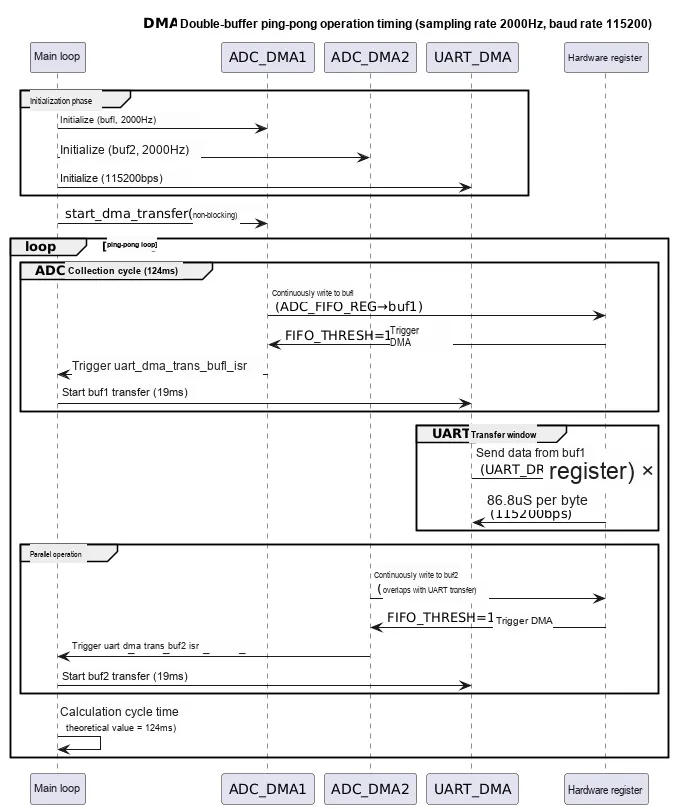
The core process of the above routine mainly implements the use of DMA to transfer data from the ADC peripheral to the memory, and uses another DMA channel to send the data out via the serial port; meanwhile, we utilize the double buffering mechanism to realize continuous Data Acquisition and transmission.
When the sampling rate is set to 2000 Hz, the UART baud rate to 115200, and the number of bytes to be transmitted to 256, the UART DMA transmission time is approximately 19 ms, while the ADC DMA transmission time is 124 ms. Therefore, we can define two buffers (buf1 and buf2) to alternately store the data transmitted via ADC DMA, and in the gap between the DMA writing operations to the two buffers, initiate UART DMA to transmit the data in the already filled buffer and send it to the computer.In this way, while the first buffer (buf1) is undergoing data processing (e. g., being sent to the serial port via DMA), the second buffer (buf2) continues with new Data Acquisition. This avoids conflicts between Data Acquisition and data processing, reduces waiting time and data processing latency, and improves the efficiency of Data Acquisition and transmission.
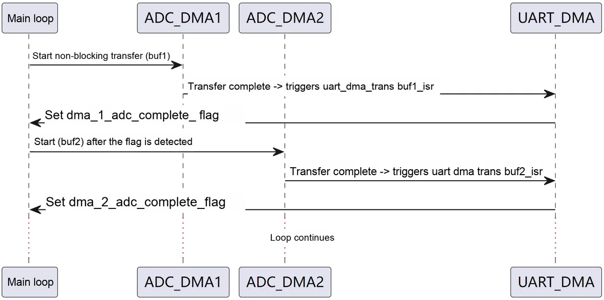
Here, we first initialize two buffers:
# Data buffer: 256 elements, each 8 bits (1 byte)
buf1 = bytearray(256)
# Second ADC data buffer
buf2 = bytearray(256)
Then create two DMA_ADC_Transfer instances:
# Initialize DMA_ADC_Transfer class instance 1 and pass in data buffer buf1
dma_adc_1 = DMA_ADC_Transfer(buf=buf1, sample_rate=2000, adc_id=0)
# Initialize DMA_ADC_Transfer class instance 2 and pass in data buffer buf2
dma_adc_2 = DMA_ADC_Transfer(buf=buf2, sample_rate=2000, adc_id=0)
Among them, dma_adc_1 is used to transfer ADC data to buf1, and dma_adc_2 is used to transfer ADC data to buf2.
Then start the DMA transfer and set the callback, taking dma_adc_1 as an example:
# First start the DMA transfer of dma_adc_1: non-blocking mode
dma_adc_1.start_dma_transfer(blocking=False,complete_callback = uart_dma_trans_buf1_isr)
Start dma_adc_1 DMA transfer, buf1 is used to store ADC data. uart_dma_trans_buf1_isr is the interrupt service routine (ISR) after the transfer is completed, which schedules subsequent data transfer operations and sets the DMA transfer completion flag after the transfer is finished:
def uart_dma_trans_buf1_isr(d: object) -> None:
    """
    Interrupt function called when the DMA transfer of ADC FIFO data is complete; schedules the corresponding callback function to run as soon as possible.

    Args:
        d (object): The DMA channel instance in use.

    Returns:
        None
    """

    # Schedule the callback function to run later
    micropython.schedule(uart_dma_trans_buf1, d)

def uart_dma_trans_buf1(d: object) -> None:
    """
    DMA transfer of serial port data, with buf1 as the read address.

    Args:
        d (object): The DMA channel instance in use.

    Returns:
        None
    """

    # Declare global variables
    global dma_uart, buf1, dma_1_adc_complete_flag

    # Wait until the ADC DMA transfer has completely finished
    while d.active():
        pass

    # Use DMA to transfer serial port data, with buf1 as the read address
    dma_uart.dma_transmit(buf=buf1, blocking=False)
    # Set the flag
    dma_1_adc_complete_flag = True
In the loop of the main program, by checking the dma_2_adc_complete_flag and dma_1_adc_complete_flag flag bits to determine whether to start a new DMA transfer:
- If
dma_2_adc_complete_flagis set toTrue, it indicates that the data transfer ofdma_adc_2tobuf2has been completed, and a new data transfer ofdma_adc_1tobuf1is started at this point - If
dma_1_adc_complete_flagis set toTrue, it indicates that the data transfer fromdma_adc_1tobuf1has been completed, and a new data transfer fromdma_adc_2tobuf2will be initiated at this point
# Poll to enable double-buffered uninterrupted data acquisition and transfer
while True:
    # Record start time
    start_time = time.ticks_us()

    # Check whether the DMA transfer of DMA_ADC_Transfer class instance 2 is complete
    if dma_2_adc_complete_flag == True:
        # Start the DMA transfer: non-blocking mode
        dma_adc_1.start_dma_transfer(blocking=False,complete_callback = uart_dma_trans_buf1_isr)
        # Do not set the flag
        dma_2_adc_complete_flag = False

    # Check whether the DMA transfer of DMA_ADC_Transfer class instance 1 is complete
    if dma_1_adc_complete_flag == True:
        # Start the DMA transfer: non-blocking mode
        dma_adc_2.start_dma_transfer(blocking=False,complete_callback = uart_dma_trans_buf2_isr)
        # Do not set the flag
        dma_1_adc_complete_flag = False

    # Record end time
    end_time = time.ticks_us()
    # Calculate the time taken by the two DMA data transfers
    dma_time = time.ticks_diff(end_time, start_time) / 1000
    # Print debug data
    print("DMA ADC run time: {:.2f} ms".format(dma_time))
We can also place the polling flag bit in a timer for execution, so as to reduce the occupation of CPU resources:
def dma_timer_check(timer: Timer) -> None:
    """
    Timer interrupt function for checking the DMA data transfer; checks whether the DMA transfer is complete,
    and if so, starts the DMA transfer of the other buffer.

    Args:
        timer (machine.Timer): The timer instance that triggered the interrupt.

    Returns:
        None
    """
    global dma_adc_1, dma_adc_2, dma_1_adc_complete_flag, dma_2_adc_complete_flag

    if dma_2_adc_complete_flag:
        dma_adc_1.start_dma_transfer(blocking=False, complete_callback=uart_dma_trans_buf1_isr)
        dma_2_adc_complete_flag = False

    if dma_1_adc_complete_flag:
        dma_adc_2.start_dma_transfer(blocking=False, complete_callback=uart_dma_trans_buf2_isr)
        dma_1_adc_complete_flag = False

# Initialize the software timer
dma_check_timer = Timer(-1)
# Set the timer to trigger the dma_timer_check function every 10ms
dma_check_timer.init(period=10, mode=Timer.PERIODIC, callback=dma_timer_check)
Next, we open the SerialPlot software and select the port corresponding to the serial port of the Raspberry Pi Pico:
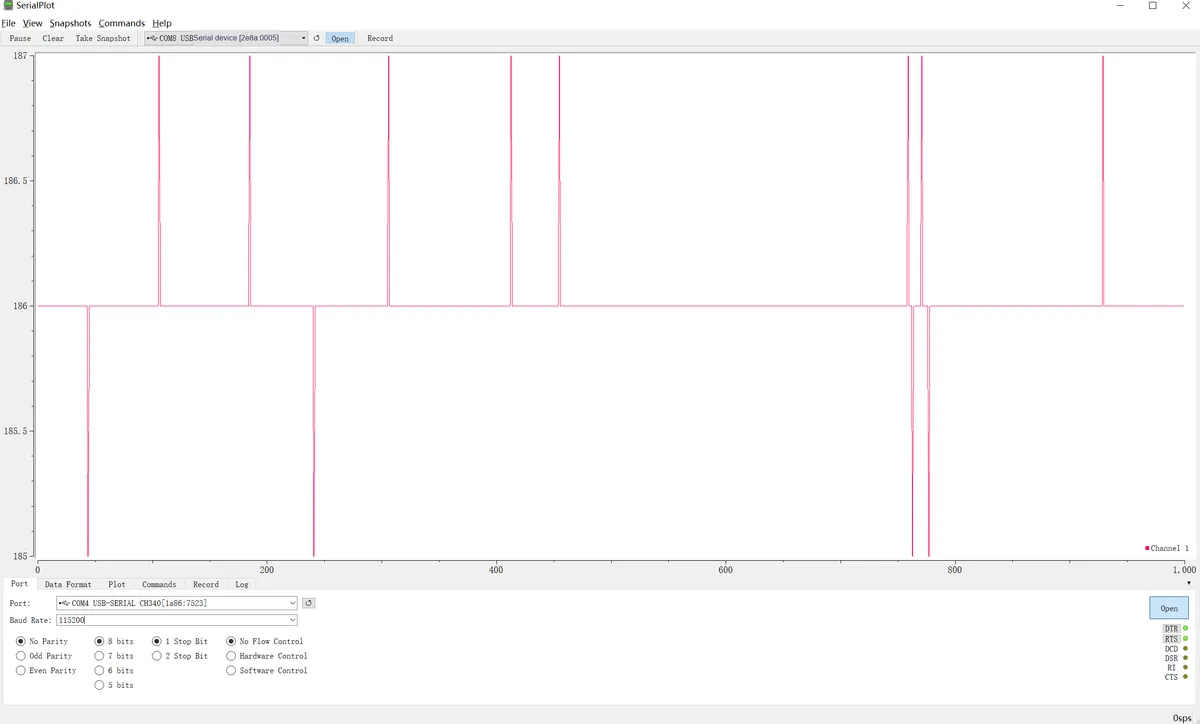
The data format is set as follows:

Burn the program, connect to the remote terminal, and the output is as follows:
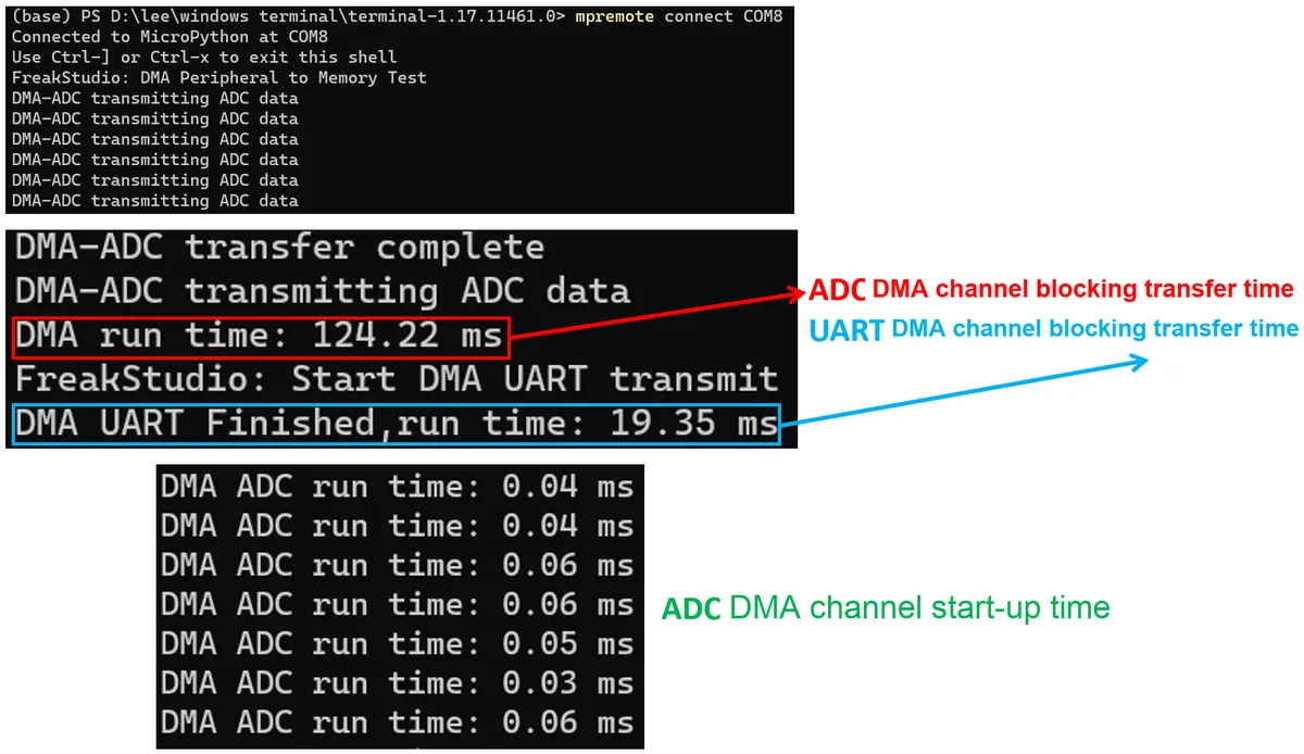
It can be seen that when DMA and the double buffer mechanism are used to realize the transmission of ADC data through the serial port, the CPU consumes very little time, only about 0.05ms.
SerialPlot The software interface is shown below, with the data update rate at this moment displayed in the lower right corner, which can be seen to be around 2000Hz:
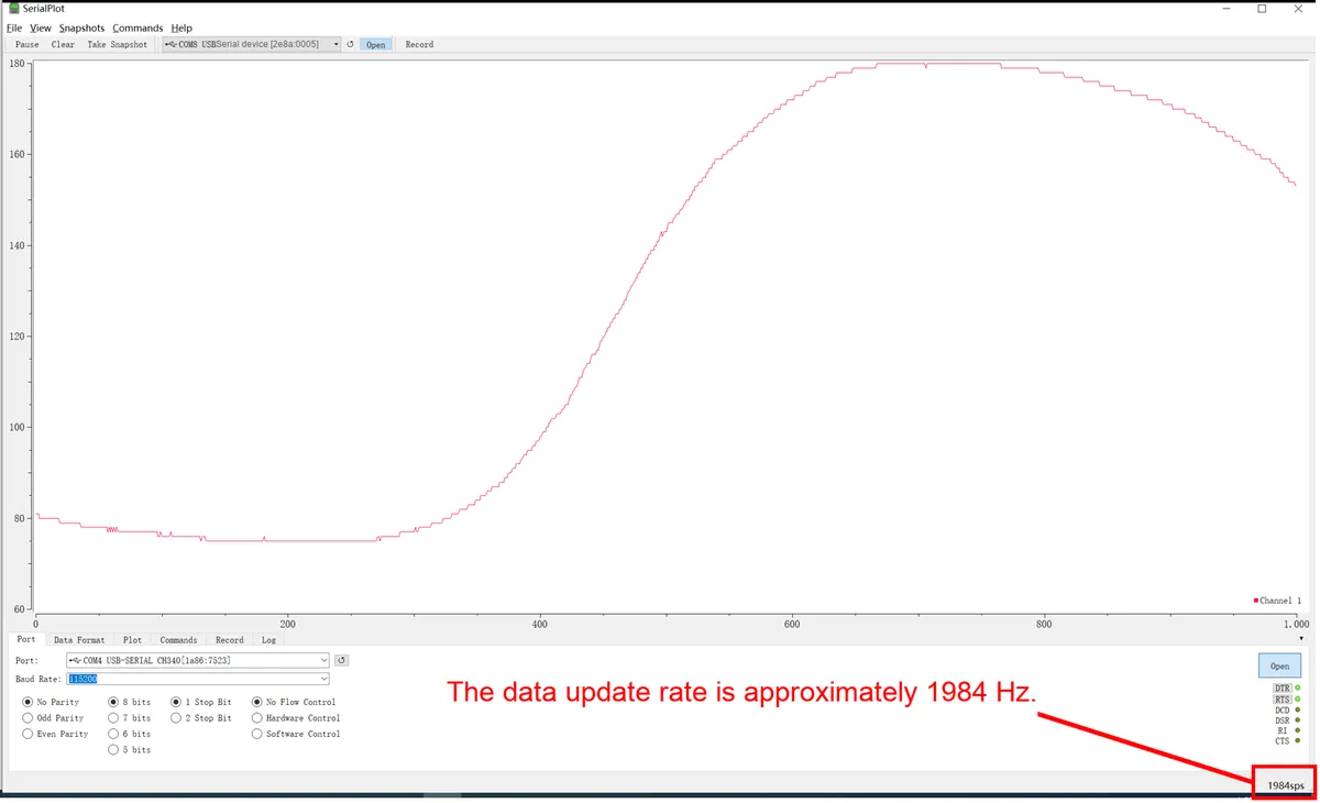
3.3.3 Application Experiment.mp4 27.3 MB
Here, when the baud rate is set to 921600 and the sampling rate is set to 45K Hz, the actually tested rate of ADC acquisition and serial port data transmission is about 40K Hz, which is mainly due to the certain delay in the DMA transmission and serial port transmission process:
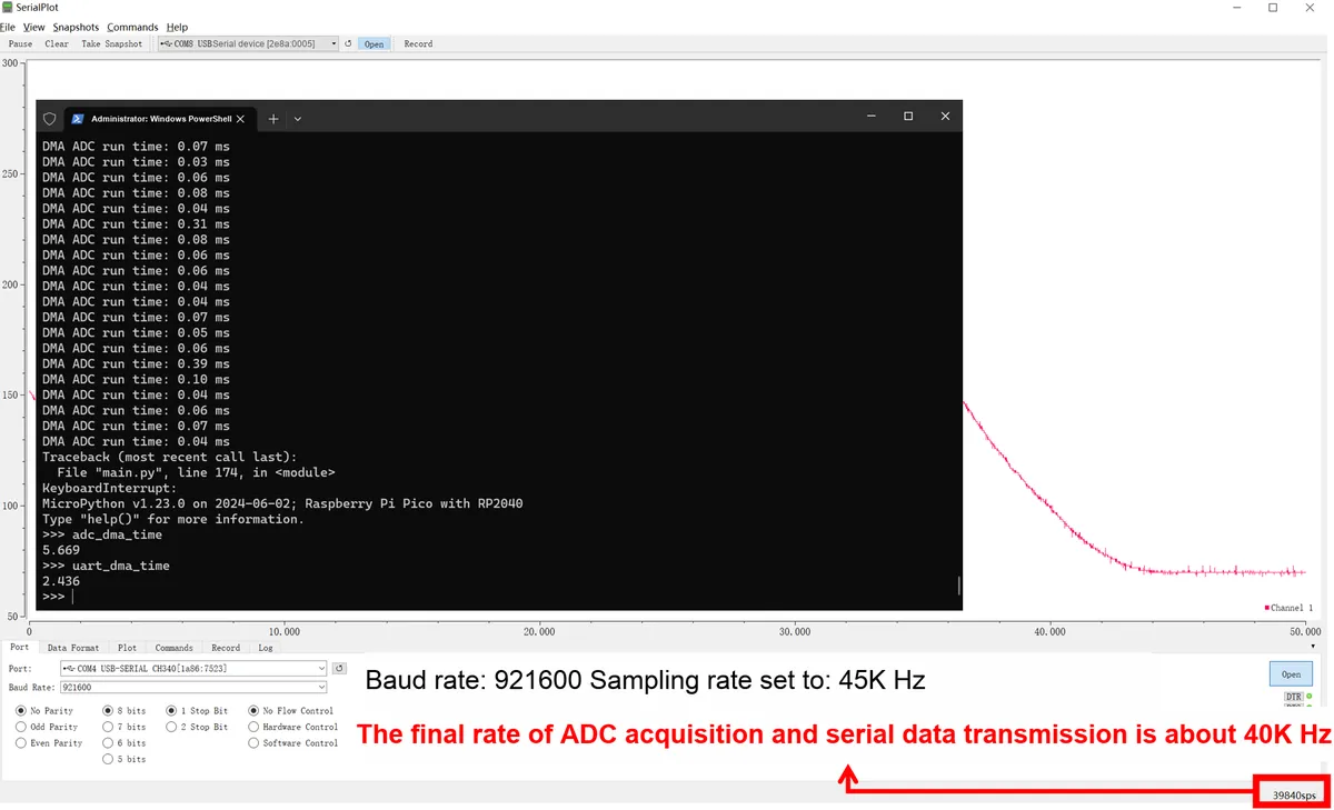
3.3.3 Application Experiment - Increased Rate.mp4 7.8 MB
If a higher data transmission rate is required, we can increase the sampling rate and serial port baud rate of ADC, and expand the buffer size. A larger buffer may lead to a lower frequency of data processing, since more data can be processed in a single operation, which helps reduce the overhead of data processing; for applications that demand high data throughput, a larger buffer can better support efficient data transmission.
3.4 DMA implements chained triggering
In the following code, we implement the operation of splicing multiple strings into a single memory buffer through the DMA transfer mechanism (chained triggering and write trigger registers), namely Scatter-gather data aggregation operation, which aggregates multiple fixed-size memory blocks into one Memory Space.
The following code can be found in the material package we provide, under the elegance-devkit v1\Demo\69 DMA_ChainTrigger folder.
The sample code is as follows:
# Python env   : MicroPython v1.23.0
# -*- coding: utf-8 -*-
# @Time    : 2024/9/8 11:04 AM
# @Author  : Li Qingshui
# @File    : main.py
# @Description : DMA class experiment, peripheral-to-memory transfer, DMA transfers data from the ADC peripheral FIFO to memory

# ======================================== Import Modules =========================================

# Import time-related modules
import time
# Import the addressof function, used to get the memory address of data
from uctypes import addressof
# Import DMA-related modules
from rp2 import DMA
# Import array-related modules
from array import array

# ======================================== Global Variables ============================================

# Define the list of strings to be concatenated
input = ["FreakStudio", ":", "test", " of the scatter", " gather", " process"]
# Create a 64-byte destination buffer (bytearray) to store the concatenated string
output = bytearray(64)

# ======================================== Functions ============================================

# ======================================== Custom Classes ============================================

def gather_strings(string_list: list, buf: bytearray) -> None:
    """
    Use DMA to concatenate the strings in a string list and store the result in the destination buffer.
    Implemented through the cooperation of two DMA channels:
    1. gather_dma channel: transfers string metadata (length + address)
    2. buffer_dma channel: moves the actual data to the destination buffer

    Args:
        string_list (list): The list of strings to concatenate; elements should be MicroPython string type
        buf (bytearray): The destination buffer; sufficient space must be pre-allocated

    Returns:
        None

    Raises:
        ValueError: If the input parameter types do not meet the requirements
        RuntimeError: If an error occurs during the DMA transfer
    """

    # Declare two DMA channels: gather_dma and buffer_dma
    # gather_dma DMA channel, used to handle string length and address information
    gather_dma = DMA()
    # buffer_dma DMA channel, used to handle the actual data copying
    buffer_dma = DMA()

    # Declare an integer array to store the string lengths and memory addresses
    gather_list = array("I")

    # Data is stored in order: string length, string address
    for s in string_list:
        # Add the string length
        gather_list.append(len(s))
        # Add the string's memory address
        gather_list.append(addressof(s))

    # Print the contents of gather_list
    # gather_list:  array('I', [11, 536906720, 1, 536904296, 4, 536904298, 15, 536906752, 7, 536904303, 8, 536904311])
    print("gather_list: ", gather_list)

    # To mark the end of the list (terminated by 0), add two 0s at the end of the list
    # Implement a null trigger, i.e. an operation that writes an all-zero value to the trigger register
    gather_list.append(0)
    gather_list.append(0)

    # Configure the gather_dma transfer control register
    # ring_size is set to 3, meaning 8-byte alignment; enable the register ring buffer
    gather_ctrl = gather_dma.pack_ctrl(ring_size=3, ring_sel=True)
    # Configure the gather_dma channel; the write addresses are the TRANS_COUNT register and the READ_ADD_TRIG register, located at the last register alias
    # i.e. registers 14 and 15
    gather_dma.config(
        read=gather_list,                   # Read the gather_list array
        write=buffer_dma.registers[14:16],  # Write the data to the buffer_dma registers:
        count=2,                            # Transfer two bytes
        ctrl=gather_ctrl                    # Transfer control register settings
    )

    # Print the parameters in the gather_dma transfer control register:
    # gather_ctrl: {'inc_read': 1, 'high_pri': 0, 'write_err': 0, 'ring_sel': 1,
    # 'enable': 1, 'treq_sel': 63, 'sniff_en': 0, 'irq_quiet': 1, 'read_err': 0,
    # 'chain_to': 0, 'busy': 0, 'inc_write': 1, 'ring_size': 3, 'bswap': 0, 'size': 2, 'ahb_err': 0}
    print("gather_ctrl:",gather_dma.unpack_ctrl(gather_ctrl))

    # Set the buffer_dma transfer control register: single-byte transfer, and configure chained transfer
    # When buffer_dma completes, it starts gather_dma for the next transfer
    buffer_ctrl = buffer_dma.pack_ctrl(size=0, chain_to=gather_dma.channel)
    # Set the destination buffer buf as the write target of buffer_dma; the actual string data will be written into buf through this DMA channel
    buffer_dma.config(write=buf, ctrl=buffer_ctrl)

    # Start the DMA transfer of gather_dma
    gather_dma.active(1)

    # Calculate the last address of gather_list
    end_address = addressof(gather_list) + 4 * len(gather_list)

    # Continuously check whether gather_dma has completed the transfer
    while gather_dma.read != end_address:
        pass

# ======================================== Initialization ==========================================

# Power-on delay of 3 s
time.sleep(3)
# Print debug information indicating the start of the main program
print("FreakStudio: DMA Chaining Triggers Test")

# ========================================  Main Program  ===========================================

# Print the initial data of the destination buffer
print(output)
# Use DMA to store the strings in the string list input into the buffer array output
gather_strings(input, output)
# Print the final data of the destination buffer
print(output)
Here, the core method for implementing the aggregation operation is gather_strings function, to which we need to pass two parameters: the list of strings to be concatenated and the target buffer for storing the concatenated result.
First, we created two DMA channel objects, gather_dma and buffer_dma, which are used to handle different tasks respectively:
gather_dma: is responsible for passing the length and address of each string tobuffer_dma.buffer_dma: Responsible for the actual data transmission (copying the content of the string to the target buffer).
Next, we define a gather_list integer array, which is used to store the length and memory address of each string; we use addressof (s) to obtain the address of the string s in memory.
Next, we configure the first DMA channel (gather_dma), for which we use the gather_dma.pack_ctrl statement to create a DMA control block, and configure the ring buffer mode of DMA. The ring buffer configuration allows gather_dma to automatically reset the address to the initial position after completing one transfer of string length and address. The explanation of the specific configuration here is as follows:
ring_size= 3: indicates 8-byte alignment is used (1<<3, i. e.,2^3 = 8), which means that when the write address offset exceeds 8 bytes, the address will automatically wrap back to the original 8-byte boundary;Simply put, each string and its corresponding address are 32-bit data, and this pair of data occupies a total of 8 bytes of space. Settingring_size= 3is to ensure that when processing each string, these two data items are transmitted together as a whole, and the 8 bytes transmitted each time will be written to the two registers ofbuffer_dma: one stores the length, and the other stores the address.ring_sel= True: Enables the ring buffer mode, which only takes effect for write addresses;Whenevergather_dmawrites a data pair (length and address) to the registers ofbuffer_dma, the write address automatically returns to the starting point. This ensures that each write operation is performed to the same two registers, preventing the write address from incrementing.
Here, we use the following command to view gather_dma the complete configuration of the control register of the channel:
print("gather_ctrl:",gather_dma.unpack_ctrl(gather_ctrl))
As can be seen, the setting of inc_read= True ensures that gather_dma increments the read address to the address corresponding to the next string after each transmission is completed;that is to say, after processing the length and address of one string, the read operation will move to the address of the next string instead of returning to the original position;inc_write= True Allows the write operation to automatically increment the write address while transferring the string content to the target buffer, so that each transferred string is sequentially placed into the target buffer to avoid overwriting previous data. It should also be noted that ring_size= 3 the write operation will automatically wrap back to the initial address once the address exceeding 8 bytes is exceeded.
Next, we configured the gather_dma channel:
read= gather_list: DMA will read the length and address fromgather_listwrite= buffer_dma.registers[14:16]: Write this information tobuffer_dma's 14th and 15th registers (these registers control the transmission of target data); the write address here corresponds to the TRANS_COUNT register and the READ_ADD_TRIG register, which are located at the last register alias (pass the length and address of a single string in the string list to the corresponding registers)

which is the trigger register that controls buffer_dma the number of transmissions of the channel and the target read address;after writing to this register, it will also start the buffer_dma channel to initiate data transmission of a single string in the string list to the target buffer.
count= 2: Two elements (length and address) are transmitted each time.ctrl= gather_ctrl: Configuration control block, used to set up the circular buffer
Similarly, we configure the second DMA channel (buffer_dma) and use the statement buffer_dma.pack_ctrl (size= 0, chain_to= gather_dma.channel) to configure the DMA control block:
size= 0: Indicates that transmission is performed in units of single bytes.chain_to= gather_dma.channel: Whenbuffer_dmacompletes one data transfer, it will automatically startgather_dma, allowinggather_dmato provide the length and address of the next string, thus forming a chained operation.
Then configure buffer_dma to write data to the target buffer buf, and use the previously created control block buffer_ctrl.
The detailed Sequence Diagram of the above chained trigger is shown below:
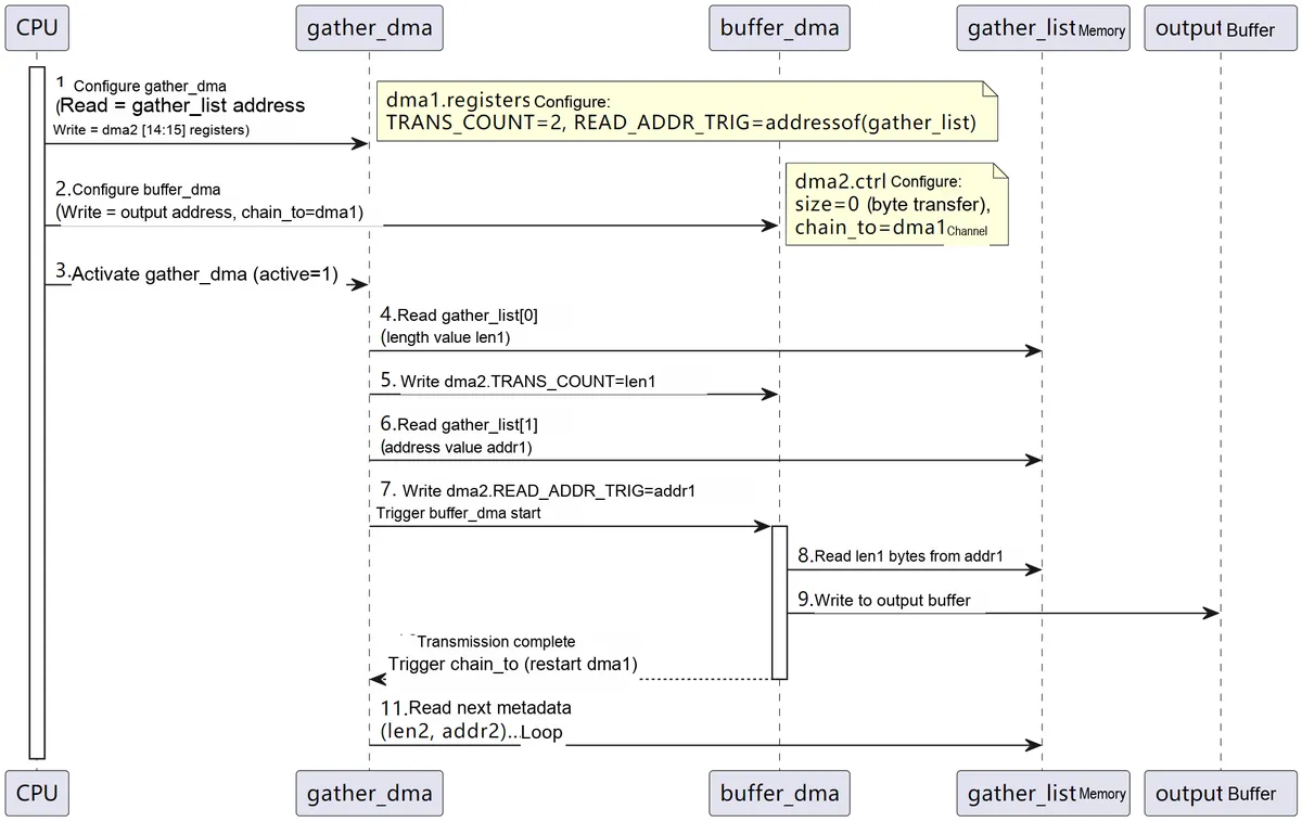
In the process of actual data transmission: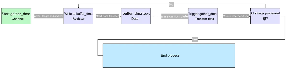
- Initial Trigger: We first start the
gather_dmachannel to begin processing the metadata of the first string.gather_dmareadsgather_listto obtainlen1andaddr1, then writes them to the registers ofbuffer_dma; writing to theREAD_ADDR_TRIGregister will triggerbuffer_dmato start. - metadata transfer:
gather_dmaAfter the channel writes data to thebuffer_dmachannel, it triggers the channel to start data transmission.buffer_dmacopieslen1bytes of data from the source string at addressaddr1to the target bufferbufaccording to the received address and length. - Chained triggering:
buffer_dmawill automatically triggergather_dmato transmit the length and address of the next string after completing one data transfer. This type of transfer is chained, that is, afterbuffer_dmafinishes transmitting a segment of string,gather_dmawill subsequently transmit the length and address of the next string, and it is determined viagather_dma.readwhethergather_dmahas completed the transmission of all lengths and addresses. - Loop processing: The above process loops continuously until
all strings in gather_listhave been completely processed.
Burn the code, connect to the remote terminal, and the output is as follows:
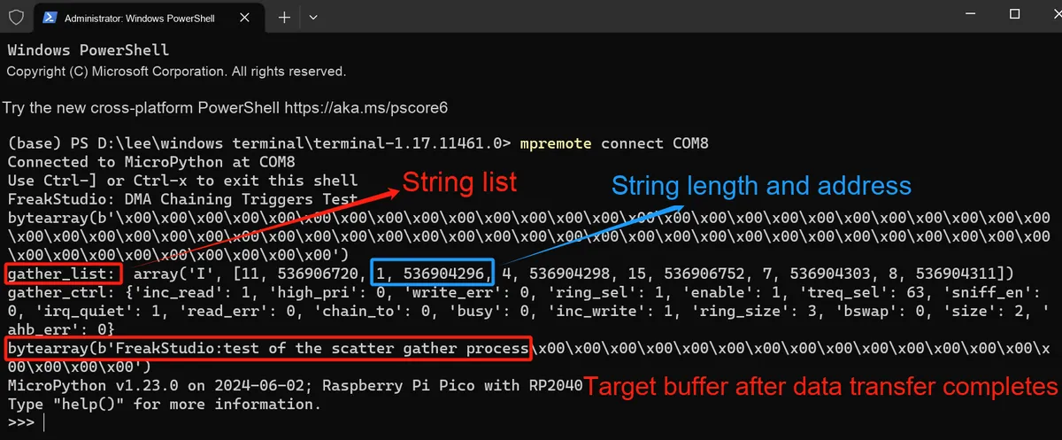
3.4 DMA Chained Trigger.mp4 1.8 MB
It can be seen that when buffer_dma completes the data transmission of one string, it will automatically trigger gather_dma to continue reading the length and address of the next string, which avoids the CPU from intervening in each transmission and greatly improves the efficiency.
References
- What Is Direct Memory Access (DMA)?
https://www.spiceworks.com/tech/hardware/articles/direct-memory-access/
- How Do DMA Controllers Work?
https://www.baeldung.com/cs/dma-controllers
- Direct Memory Access (DMA)
https://www.embedded.com/introduction-to-direct-memory-access/
- class DMA – access to the RP2040’s DMA controller
https://docs.micropython.org/en/latest/library/rp2.DMA.html
- Direct memory access
https://en.wikipedia.org/wiki/Direct_memory_access
- Direct Memory Access
https://www.techopedia.com/definition/2767/direct-memory-access-dma
- RP2040 (Raspberry Pi Pico) DMA
https://www.taterli.com/7524
- Using Direct Memory Access (DMA) on the RP2040 chip
https://blog.adafruit.com/2023/01/24/
Version History
Version Number | Modifier | Time | Content |
v1.0.0 | Li Zisheng | 2025/09/19 | Initialize the document, based on MicroPython version v1.23.0. |
v1.0.1 | Li Zisheng | 2025/12/24 | Optimized part of the principle explanations, based on MicroPython v1.23.0. |