
Contents
- 1. Hardware Explanation
- 1.1 Low Power Mode
- 1.2 Low-Power Modes on the Raspberry Pi Pico
- 2. Software Control Method
- 2.1 Method for Setting Low-Power Mode in the machine Module
- 2.2 Issues with Raspberry Pi Pico Entering Low-Power Mode When Using MicroPython
- 3. Application Examples
- 3.1 Idle Mode Experiment
- 3.2 Experiment of Light Sleep Mode
- 3.3 Deep Sleep Mode Experiment
- References
- Version History
1. Hardware Explanation
1.1 Low Power Mode
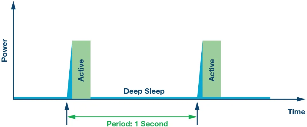
In the application of microcontrollers, low-power modes refer to a series of operating states designed to reduce system power consumption, extend battery life or cut energy usage. These modes achieve low-power operation by means such as lowering the clock frequency, turning off unnecessary peripherals and processor cores, and even entering deep sleep states.
1.1.1 Definition and Principle of Low-Power Mode
Low-power mode refers to an operating mode of a microcontroller that maintains the operation of certain necessary functions (such as timing, counting, or external event monitoring) while reducing power consumption. These modes are commonly used in battery-powered devices, such as IoT sensors, wearable devices, or portable electronic products, to extend the battery life of the devices.
The low-power mode achieves power consumption reduction through the following methods:
- Clock Management: Reduce power consumption by lowering the system clock frequency or disabling partial clock signals
- Peripheral Management: Disable or pause unnecessary peripherals (such as ADC, UART, I2C, etc.) to reduce their power consumption
- Processor Management: Put the processor into a low-power state, such as sleep or deep sleep state, to reduce the dynamic power consumption of the processor
- Power Management: Some microcontrollers support power gating for certain modules or peripheral devices, completely cutting off their power supply to achieve lower static power consumption.
1.1.2 Types of Operating Modes of Single-Chip Microcomputers
From the perspective of power consumption, the operating modes of single-chip microcomputers can be divided into the following categories:
- Run Mode (Operating Mode)
- Definition: This is the normal operating mode of the microcontroller, in which all modules and peripherals are active, and the system runs at the full-speed clock frequency.
- Features: Highest power consumption, but also the highest performance
- Idle Mode
- Definition: In idle mode, the CPU of the microcontroller stops running, while other peripherals and clocks remain active.
- Features: Compared with the active mode, it features lower power consumption and is suitable for use when waiting for external events or interrupts.
- Sleep Mode
- Definition: In sleep mode, the CPU stops running, and most peripherals also enter a low-power state, but certain critical peripherals (such as timers and RTC) remain operational.
- Features: Further reduces power consumption, and is suitable for scenarios where the processor does not need to perform tasks temporarily
- Deep Sleep Mode
- Definition: In deep sleep mode, the CPU and most peripherals are powered off, with only a tiny number of peripherals (such as the RTC) and RAM data retained.
- Features: Ultra-low power consumption, suitable for scenarios where no task processing is required for a long period; it usually relies on external interrupts or timers to wake up the system.
- Hibernate Mode
- Definition: This is the power mode with the lowest power consumption. In this mode, most system modules and power supplies are turned off, and only a very small number of wake-up sources (such as RTC or external interrupts) are retained.
- Features: It features the lowest static power consumption, making it suitable for extremely long sleep states; the system usually requires reinitialization after wake-up.
- Stop Mode
- Definition: In stop mode, all clock signals are stopped, and only specific wake-up sources can wake up the microcontroller.
- Features: The system consumes almost no dynamic power and has extremely low static power consumption, making it suitable for scenarios requiring long periods of inactivity.
1.1.3 Wake-up Mechanism
The wake-up mechanism of a microcontroller unit (MCU) involves restoring the system from low-power modes (such as sleep mode, hibernate mode, etc.) to a normal operating state. Common wake-up sources for MCUs include:
- External Interrupt: An external interrupt source (e. g., a GPIO pin) is connected to the external interrupt line of the microcontroller. In low-power mode, the external interrupt source can continue monitoring external events; when an interrupt condition is detected, the external interrupt will trigger an interrupt request to wake the system up from the low-power mode.
- Timer: A timer can trigger an interrupt after a preset time interval to wake up the system. It continues to operate in low-power mode, and generates an interrupt signal when the preset time interval elapses; upon receiving the timer interrupt, the system wakes up from the low-power mode.
- Real-Time Clock (RTC): The RTC clock continues to operate in low-power mode, typically with extremely low power consumption. When a set time point or cycle is reached, the RTC generates an interrupt signal, and the system is woken up from the low-power mode via the RTC interrupt.
- Internal events: Some internal events (such as peripheral operation completion, data ready status, etc.) can also trigger wake-up. Internal events are triggered by setting internal flag bits or registers; when an event occurs, the system detects an internal interrupt and wakes up from the low-power mode.
1.2 Low-Power Modes on the Raspberry Pi Pico
The RP2040 microcontroller offers a range of options for reducing both dynamic and static power consumption, helping devices achieve higher energy efficiency across different operating scenarios.
Dynamic power reduction options include:
- Top-tier clock gating: It enables independent control over the clock of each peripheral and functional block, reducing unnecessary power consumption by enabling or disabling the clock as needed.
- Automatic Clock Gating: Automatically controls the top-level clock gating based on the processor's sleep state, and automatically turns off unnecessary clocks when the processor enters sleep mode
- Dynamically adjust the system clock frequency or clock source: For example, it is possible to switch to the internal oscillator and disable the PLL and crystal oscillator to reduce power consumption
- Sleep state with zero dynamic power consumption: In this state, all clocks and oscillators are disabled, and the system can be woken up to resume normal operation via GPIO events or RTC interrupts
Static power reduction options include:
- Memory enters a low-power state for state retention : reduces the power consumption of the memory without affecting data preservation
- Power gating for peripheral devices: For example, ADCs and temperature sensors support power gating, which allows them to be powered down when not in use to reduce power consumption
Clock Domain Management of RP2040
In a system, a clock domain refers to all circuit parts or modules driven by the same clock signal, and these circuit modules operate at the same clock frequency and phase. In a complex system, there may be multiple clock domains, and each clock domain may run at a different clock frequency, phase, or even from a different clock source.
The primary objective of clock domain management is to optimize system power consumption, performance, and the reliability of data transmission. Specifically, the purposes of clock domain management encompass the following aspects:
- Power Consumption Management: Reduce unnecessary power consumption by turning on, turning off, or adjusting the frequency of clock signals in different clock domains.
- Clock domain interaction: When transmitting data between different clock domains, it is necessary to handle the clock domain interaction problem to avoid data invalidity or instability.
- Performance optimization: By adjusting the clock frequency, the system performance can be dynamically optimized under different operating modes
Common clock domain management methods include:
- Clock gating: A technique that reduces dynamic power consumption by controlling the transmission of the clock signal and turning off the clock signal of a module when it does not need to operate.
- Dynamic Clock Frequency Scaling: It dynamically adjusts the clock frequency according to system requirements: raising the clock frequency when high performance is needed, and lowering the clock frequency during idle or low-load periods to save energy.
- Clock Domain Interaction Management: The clock domain interaction management technology is used to solve the problem of data transmission between different clock domains and ensure the stability and correctness of cross-domain data transmission. Commonly used technologies include double-edge registers, asynchronous FIFOs, and handshake protocols, which are applied to mitigate the issues of cross-clock domain data transmission.
- Sleep and Wake-up Control: When entering the low-power mode, the system can shut down most clock domains, and only a few necessary clock domains remain active to resume operation upon quick wake-up.
In the RP2040, each clock domain (such as the system clock) can drive multiple hardware modules, but not all modules need to run simultaneously. To avoid unnecessary power consumption, the RP2040 allows the endpoints of individual clocks to be disabled at any time. For example, when the UART is not needed, its clock can be temporarily disabled; when re-enabled later, the state of the peripheral will not change, and no reset or reinitialization is required.
In the RP2040 microcontroller, the sleep mode (SLEEP State) and the dormant mode (DORMANT State) are two states designed to reduce system power consumption:
- Sleep Mode (
SLEEP State): When both Cortex-M0+ processors are in sleep state (e. g., executing WFI or WFE instructions) and the system DMA has no ongoing transfers, the RP2040 enters sleep mode; when either processor is woken up by an interrupt, the RP2040 exits sleep mode.- Clock Management: In sleep mode, the top-level clock gating of the system is controlled by the SLEEP_ENx registers instead of the WAKE_ENx registers. This enables more aggressive gating of the clock tree while the processor is in sleep state to reduce power consumption.
- Usage Scenario: For example, if the system is in a sleep state and waiting for a character interrupt from the UART, the entire system (with the exception of the UART) can undergo clock gating. After the UART generates an interrupt to wake up the processor, the system exits the sleep mode and switches back to the WAKE_ENx clock mask.
- Sleep Mode (
DORMANT State): The sleep mode is a true zero dynamic power consumption sleep state, in which all clocks (including all oscillators) are disabled. The system can be woken up via a GPIO event (high/low level or rising/falling edge) or an RTC interrupt; after waking up, an oscillator is restarted, and its output is unlocked once stabilized. The system state remains unchanged, and code execution resumes from the point where it was before entering sleep.- Clock Management: In sleep mode, all clocks and oscillators are disabled. If the RTC is relied upon to wake up the system, the RTC must have an external clock source. In addition, PLLs should be turned off before entering sleep mode to avoid unnecessary power consumption, and need to be restarted and reconfigured after exiting sleep mode.
- Usage Scenario: This mode is ideal for scenarios where the system remains inactive for an extended period but requires rapid resumption, such as deep sleep during standby.
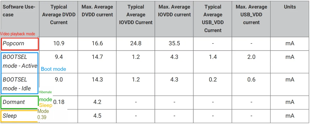
The power consumption of Raspberry Pi Pico in various modes is shown in the table below (operating frequency: 48MHz):
The following are some key registers related to sleep mode and hibernation mode:
- SLEEP_ENx (SLEEP_EN0, SLEEP_EN1) Registers: These registers are used to control the activation and deactivation of individual clock domains when the processor enters the sleep state. By setting the corresponding bits in the SLEEP_ENx registers, you can specify which clocks will continue operating and which will be turned off when the processor enters sleep mode, thereby reducing unnecessary power consumption.
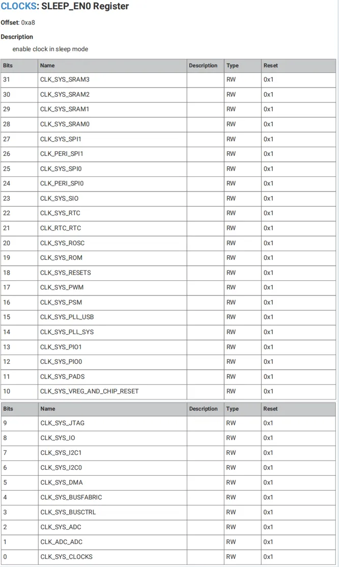
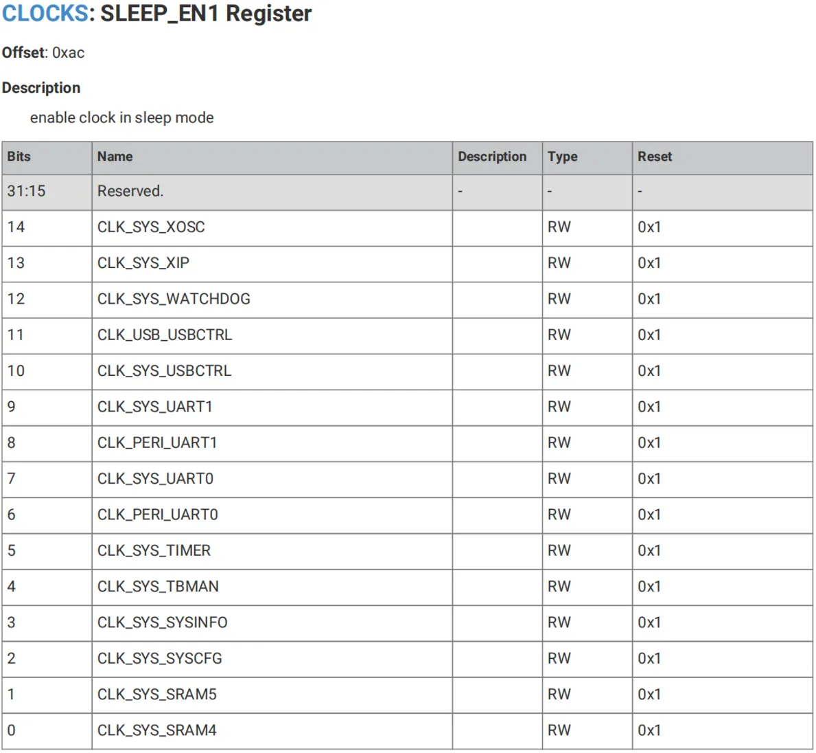
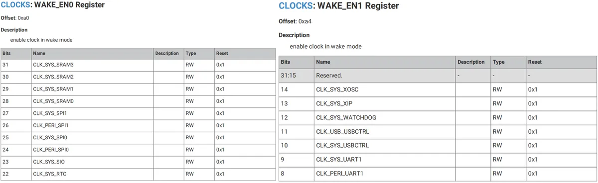
- WAKE_ENx (WAKE_EN0, WAKE_EN1) Registers: These registers are used to control which clock domains should be enabled when the system is in the Wake state. When the processor wakes up from the SLEEP state, the system will switch to the clock configuration defined by the WAKE_ENx registers, thereby re-enabling the necessary clock domains.
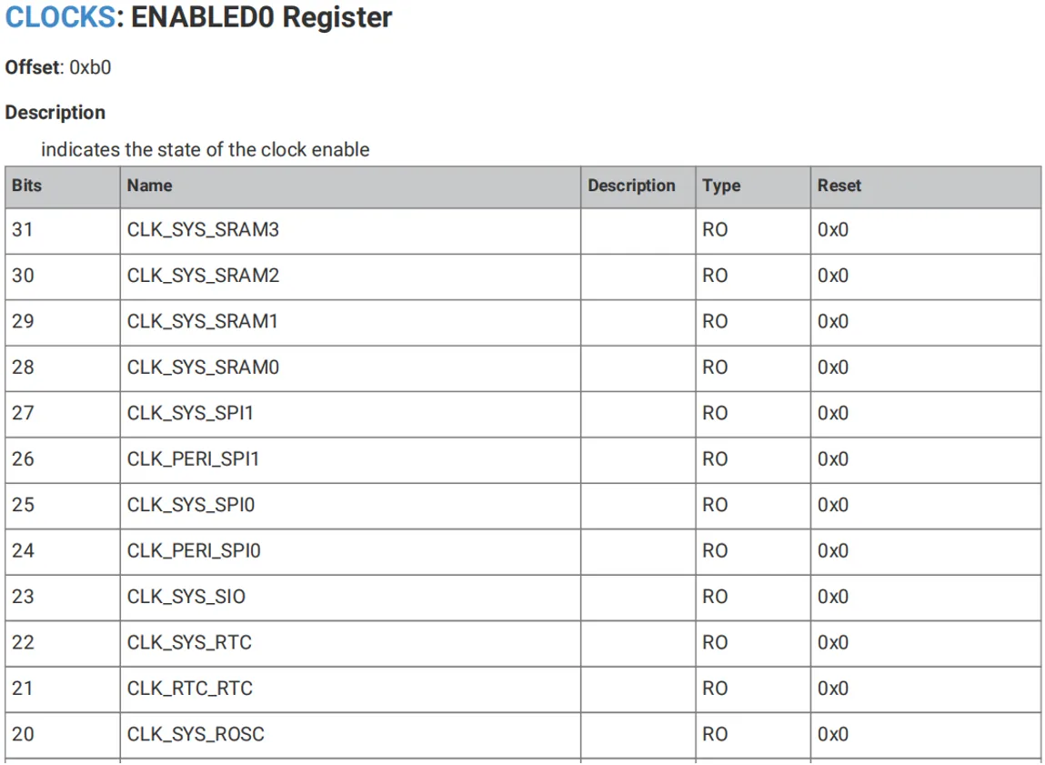
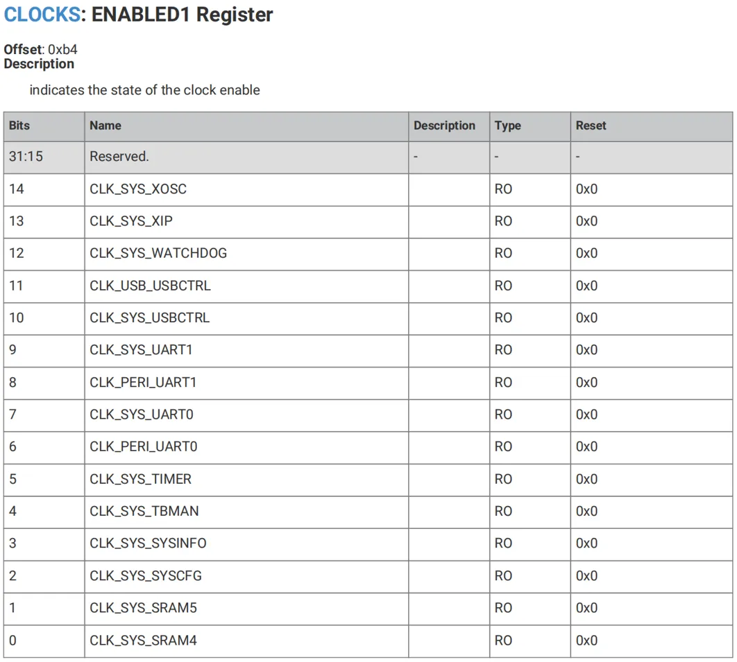
- ENABLEDx (ENABLED0, ENABLED1) Registers: These registers indicate the current enable status of each clock domain, showing which clock domains are enabled and which are disabled in the current state (whether in sleep mode or wake-up mode).
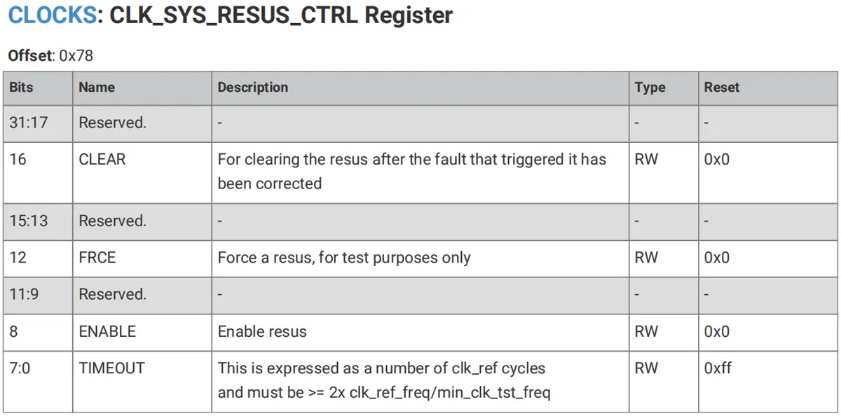
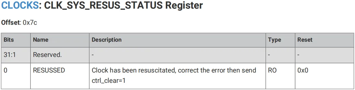
- CLK_SYS_RESUS_CTRL and CLK_SYS_RESUS_STATUS Registers: These registers are associated with the system clock recovery function. When the system enters an extremely low-power state due to certain conditions, these registers can help manage the re-enabling of the system clock, ensuring that the system can resume normal operation when required.
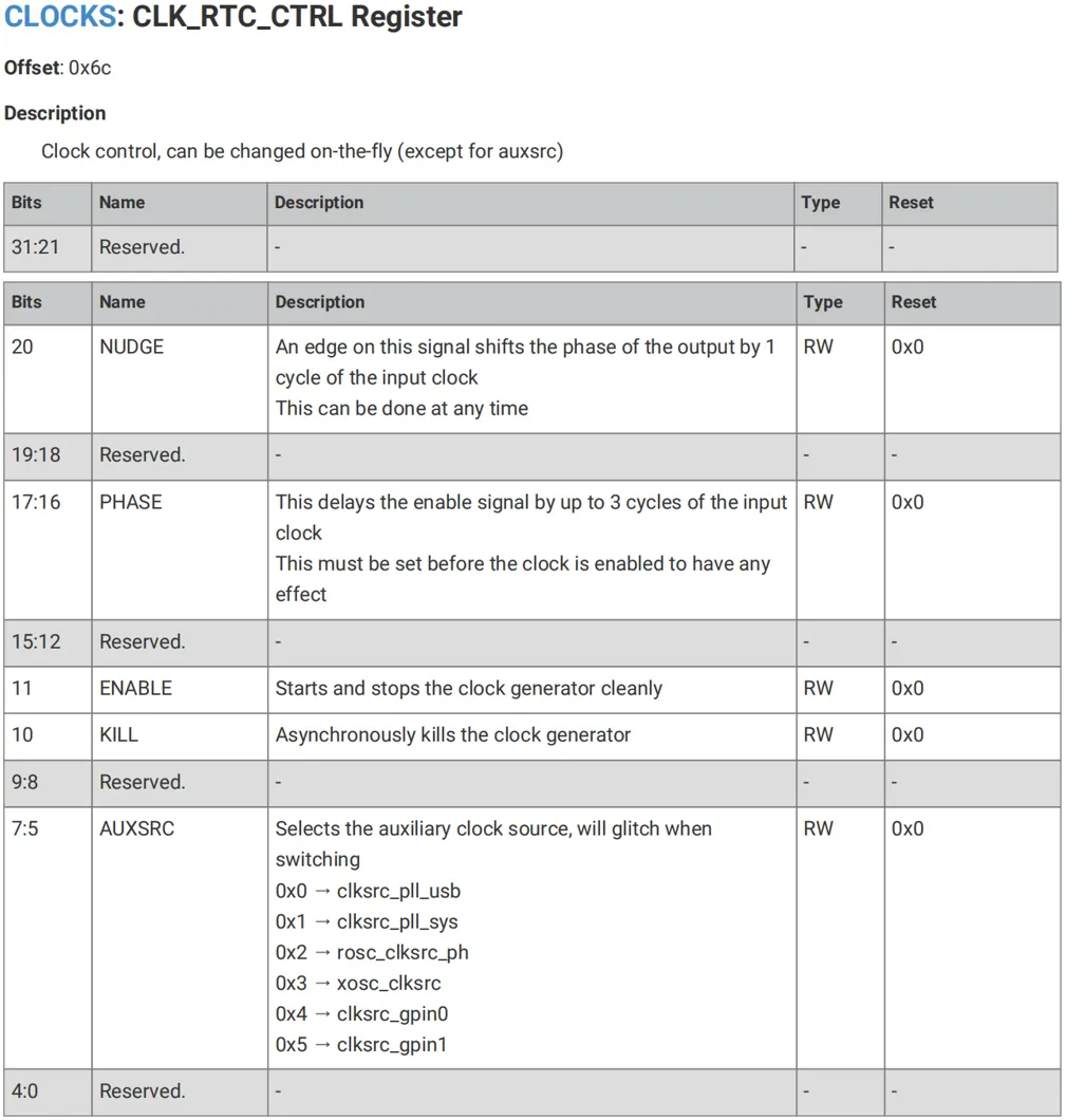
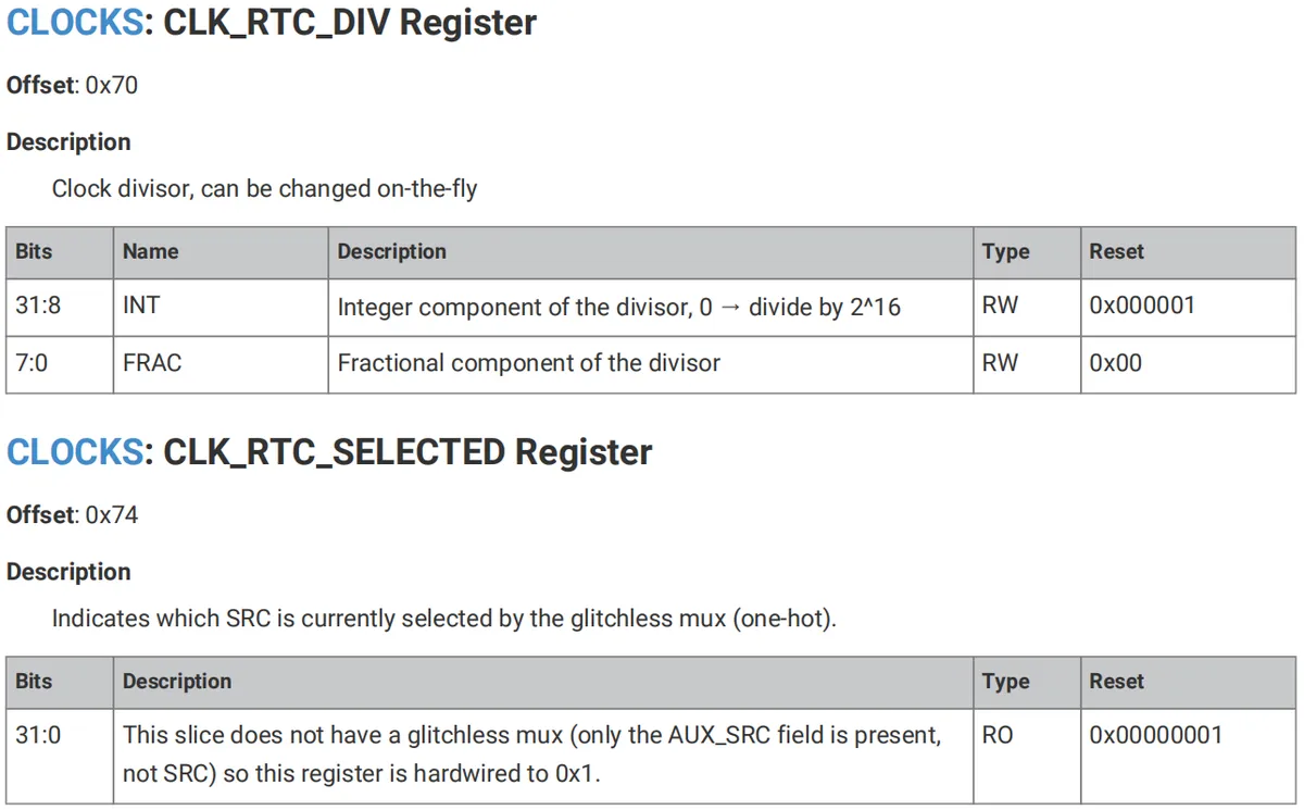
- Registers CLK_RTC_CTRL, CLK_RTC_DIV and CLK_RTC_SELECTED: These registers control the clock source selection and divider settings of the Real-Time Clock (RTC). When the processor enters the DORMANT state, if the system relies on the RTC for wakeup, it is mandatory to ensure that these registers have been properly configured and the RTC is provided with an external clock source to sustain its operation.
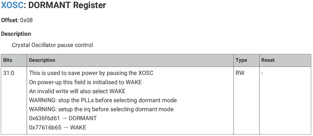
- DORMANT Mode Control: By writing a specific key value to the DORMANT register, the system can enter a true zero dynamic power consumption sleep state (DORMANT state). In this state, all clocks (including oscillators) are disabled, and the system is only woken up by GPIO events or RTC interrupts.
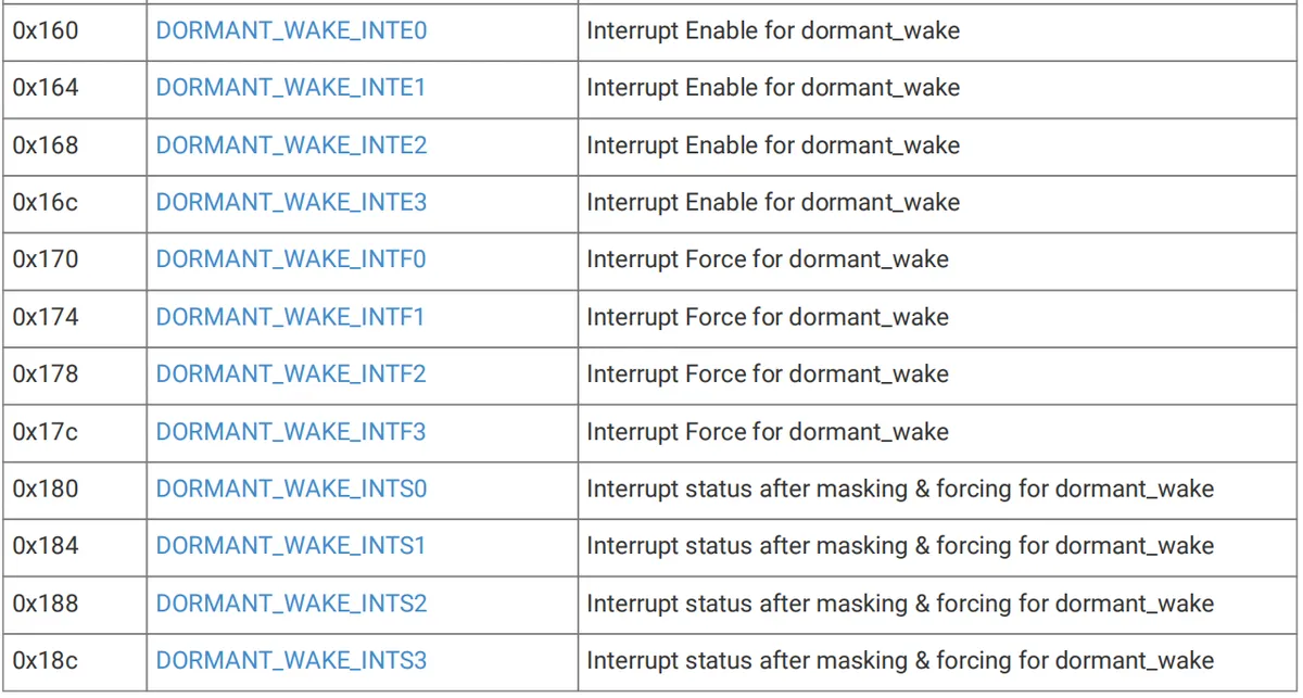
The DORMANT_WAKE_INTEx register is used to enable the wake-up interrupt for DORMANT mode, the DORMANT_WAKE_INTFx register is used to forcibly trigger the wake-up interrupt for DORMANT mode, and the DORMANT_WAKE_INTSx register is used to indicate the status of the wake-up interrupt for DORMANT mode:
2. Software Control Method
2.1 Method for Setting Low-Power Mode in the machine Module
In the machine module of MicroPython, there are multiple methods for low-power modes and wake-up mechanisms, as shown in the table below:
Method | Description |
machine.lightsleep([time_ms]) | Put the device into a light sleep state. In this state, most peripherals (such as the CPU) stop working, but the memory remains active, and GPIO interrupts or timer events can wake up the device. Light sleep retains all RAM and system state. After waking up, execution resumes from the point where sleep was requested, and all subsystems will function normally. If On the Raspberry Pi Pico, the implementation of this method has flaws, which will be detailed later in this document. Regardless of whether a timeout is set, execution may resume at any time if there are events that require processing. These events, or wake-up sources, should be configured before entering sleep, such as pin changes or RTC timeouts. |
machine.deepsleep([time_ms] | Put the device into deep sleep mode. In this state, most peripherals of the device (including the CPU and memory) will stop operating, with only a few modules (such as the RTC) remaining active. The power consumption in deep sleep mode is extremely low, making it suitable for long-term standby operations. Deep sleep may not retain RAM or other states of the system (such as peripherals or network interfaces). After waking up, execution will restart from the main script, similar to a hard reset or power-on reset. On the Raspberry Pi Pico, the implementation of this method has defects, which will be detailed later.
|
machine.idle() | Put the device into idle mode, in which the CPU stops executing instructions while the peripherals continue to operate. This can be used for short-term power-saving operations. |
machine.wake_reason() | It is used to check the reason why the device wakes up from low-power modes (such as deep sleep), which can help developers determine the wake-up source. The return values are as follows:
This method is not available on the Raspberry Pi Pico. |
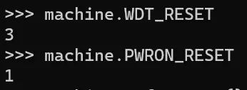
machine.reset_cause() | It is used to check the reason for the last restart of the device. This is very useful for determining whether the device is started due to a normal reset or a wake-up operation (such as exiting the low-power mode). The return values are as follows:
|
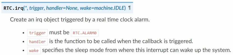
Some platforms provide an RTC (Real-Time Clock) for setting scheduled wake-ups. For example, in deep sleep mode, you can configure a timer via the RTC to wake the device after a specified time, with instructions available here: https://docs.micropython.org/en/latest/library/machine.RTC.html
Open the terminal and enter the command dir (machine), the output is as follows:

It can be seen that there is no machine.wake_reason () on the Raspberry Pi Pico. Meanwhile, for the machine.reset_cause () method, its return values only include WDT_RESET and PWRON_RESET.
2.2 Issues with Raspberry Pi Pico Entering Low-Power Mode When Using MicroPython
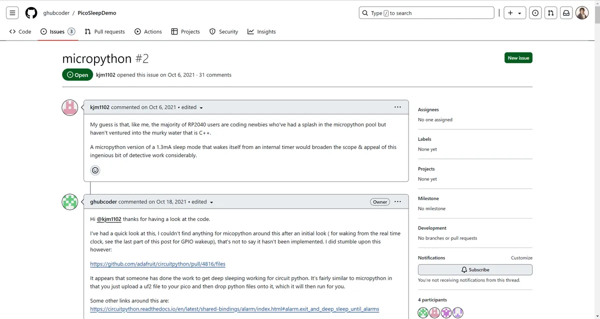
Here, it should be noted that the machine.deepsleep ([time_ms]) method and machine.lightsleep ([time_ms]) method in Raspberry Pi Pico have implementation flaws (on MicroPython v1.23.0), which cannot wake up correctly, and the sleep time of Pico is limited to less than 127 seconds. For specific instructions, please refer to the following link:
https://github.com/ghubcoder/PicoSleepDemo/issues/2
https://github.com/orgs/micropython/discussions/9969
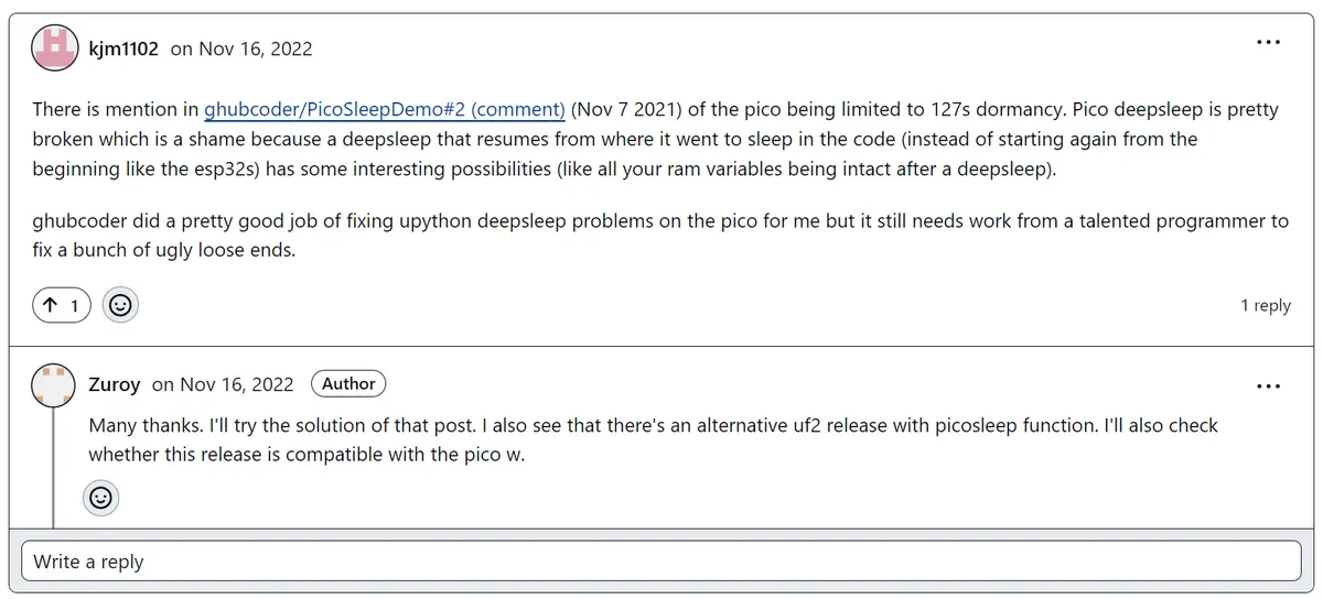
Simply put, after deep sleep (or hibernation), the UART on the Pico may exhibit unexpected behaviors, such as limiting the number of characters it can send or receive; additionally, it will be unable to reconnect to the REPL after waking from sleep, and communication issues with the computer will arise after reinitialization.
For solutions, you can refer to the following link:
Deep sleeping the Raspberry Pico with Micropython
https://ghubcoder.github.io/posts/deep-sleeping-the-pico-micropython/

Simply put, this is achieved by compile the custom MicroPython firmware that includes the Pico SDK and pico-extras libraries, and using the author's custom modules for deep sleep and wake-up to avoid the above issues. Here, since low-power mode is not commonly used in practical applications by beginners, and most of the device's power consumption comes from the external sensors or driving devices in use, therefore, we recommend that if you need low power consumption, you should try to use the machine.idle () method.
Meanwhile, it should be noted that in the Raspberry Pi Pico, since timers can only be used as software timers in the MicroPython environment, they cannot wake up the CPU. This limitation means that if the device enters a low-power mode, the software timer will not trigger any hardware interrupt to wake up the device. Meanwhile, in the RTC peripheral of the Raspberry Pi Pico, there is no interrupt method, and it also cannot wake up the CPU.

When the Raspberry Pi Pico enters low-power mode, it can only be woken up via an external interrupt.
3. Application Examples
In the application examples, we will focus on explaining the light sleep mode and the idle mode. Since the deep sleep mode of the Raspberry Pi Pico completely shuts down the CPU and most peripherals, making it impossible for the device to execute any instructions during sleep and requiring a specific external event to wake up, the deep sleep mode is not covered in this discussion.
Power Consumption Measurement
3.1 Idle Mode Experiment
In the following example, we call machine.idle () function in a loop to put the CPU into idle mode and reduce power consumption. By cooperating with external interrupts, the CPU can be quickly woken up to process when an external event occurs.
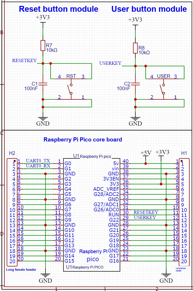
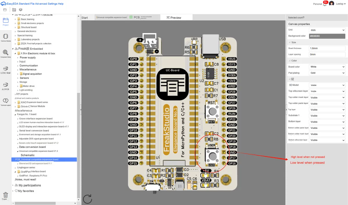
Here, on the Fengya No. 1 Board - Universal Compatible Expansion Board, we use the GP22 pin of the Raspberry Pi Pico to connect to the button USERKEY, and set GP22 to falling-edge trigger. Pressing the button can wake up the CPU. As can be seen on our Fengya No. 1 Board - Universal Compatible Expansion Board, the user button USERKEY is set to high level via a pull-up resistor when not pressed:
When the key is pressed, it outputs a low level, so it is configured as falling-edge triggered:
The following code can be found in the resource package we provide, in the elegance-devkit v1\Demo\55 Machine_Idle folder.
The sample code is as follows:
# Python env   : MicroPython v1.23.0
# -*- coding: utf-8 -*-
# @Time    : 2024/8/23 2:31 PM
# @Author  : Li Qingshui
# @File    : main.py
# @Description : Low-power experiment, using the machine.idle() method to enter idle mode

# ======================================== Import Modules ========================================

# Import the hardware module
import machine
# Import time-related modules
import time

# ======================================== Global Variables ============================================

# ======================================== Functions ============================================

# Define the external interrupt handler function
def button_handler(pin: machine.Pin) -> None:
    """
    External interrupt handler function; after the button is pressed, toggles the LED state and prints a message.

    Args:
        pin (machine.Pin): The button instance that triggered the interrupt.

    Returns:
        None

    Raises:
        None
    """
    # Declare global variables
    global led

    # Toggle the LED
    led.toggle()

    # Print debug information
    print("Button pressed!")

# ======================================== Custom Classes ============================================

# ======================================== Initialization ==========================================

# Power-on delay of 3 s
time.sleep(3)
# Print debug information
print("FreakStudio : Using irq to wake up Pico of idle mode")

# Create an LED object
led = machine.Pin(25, machine.Pin.OUT)
# Set GPIO22 as input and enable the pull-up resistor
button_pin = machine.Pin(22, machine.Pin.IN, machine.Pin.PULL_UP)
# Configure the external interrupt
button_pin.irq(trigger=machine.Pin.IRQ_FALLING, handler=button_handler)

# ========================================  Main Program  ===========================================

# Main program loop
while True:
    # Call the machine.idle() function in the loop to reduce CPU power consumption
    machine.idle()

    # Print a message to indicate the main loop is running
    print("System is idling...")

    # To avoid printing too frequently, add a delay
    time.sleep(1)
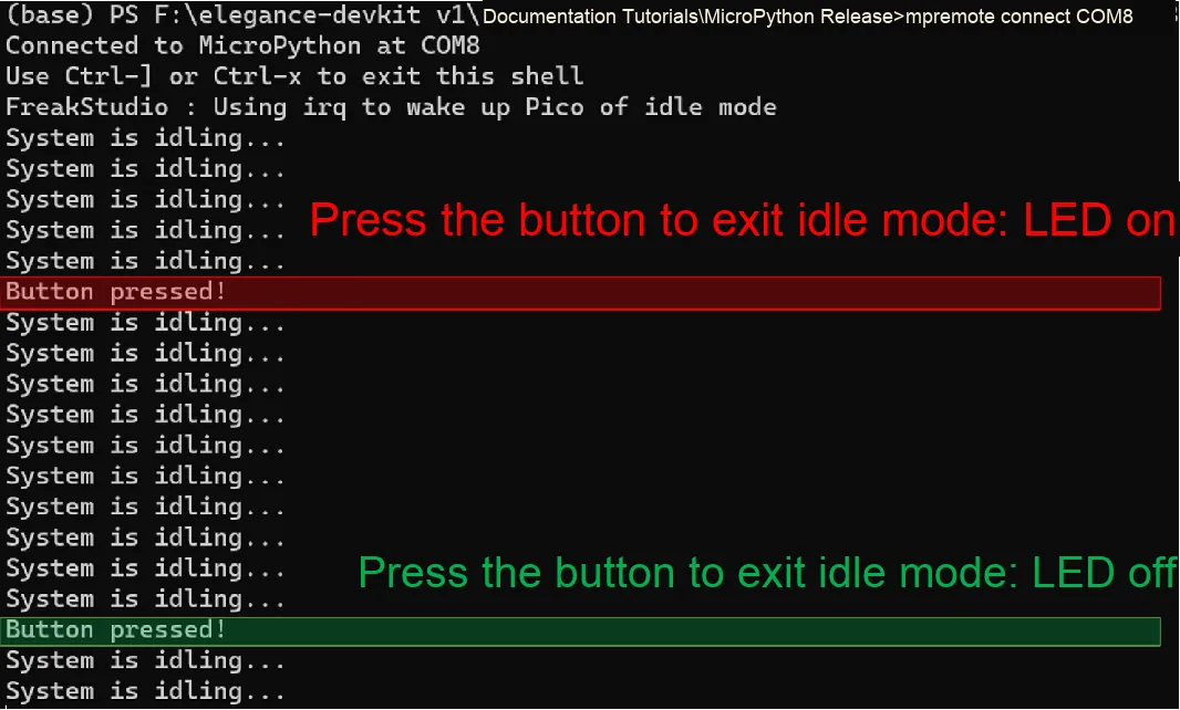
Burn the code, connect to the remote terminal, and the output is as follows:
3.1 Application Experiment.mp4 35.4 MB
As can be seen, when we press the key, the external interrupt will wake up the CPU, LED and the on/off state of the LED will be reversed, while the terminal outputs debug information at the same time.
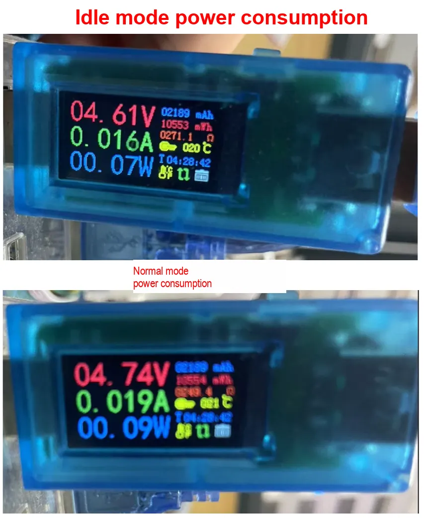
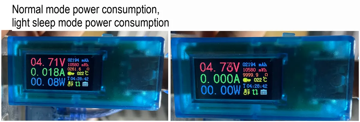
Now we will use a USB power meter to connect to the USB port of Fengya No. 1 Board - Universal Compatible Expansion Board Raspberry Pi Pico to compare the power consumption under the two modes:
3.2 Experiment of Light Sleep Mode
Here, we use machine.lightsleep () to enter the light sleep mode. The sleep duration can be specified when entering this mode to achieve better power consumption optimization; we connect a key to the GP22 pin of the Raspberry Pi Pico, configure GP22 to be triggered on the falling edge, so that pressing the key can wake up the CPU; and use the serial peripheral to output debug information.
Before conducting the shallow sleep mode experiment, we first need to connect the MiniUSB data cable to the serial port on the Fengya No. 1 Board - Universal Compatible Expansion Board. Here, GP0 and GP1 are the default pins of the hardware serial port UART0 of the Raspberry Pi Pico:
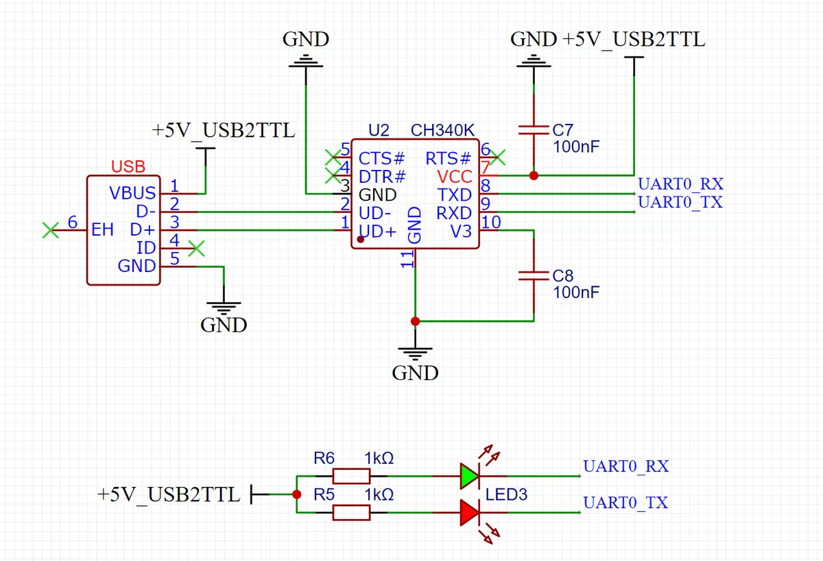
The physical image after insertion is as follows:
Here, on the Fengya No.1 Board - Universal Compatible Expansion Board , we use the GP22 pin of the Raspberry Pi Pico to connect the button USERKEY , set GP22 as the lower edge trigger, press the button to wake up the CPU, which can be seen in our Fengya No.1 Board - Universal Compatible Expansion Board . The user button USERKEY is set to a high level through the pull-up resistor when not pressed:
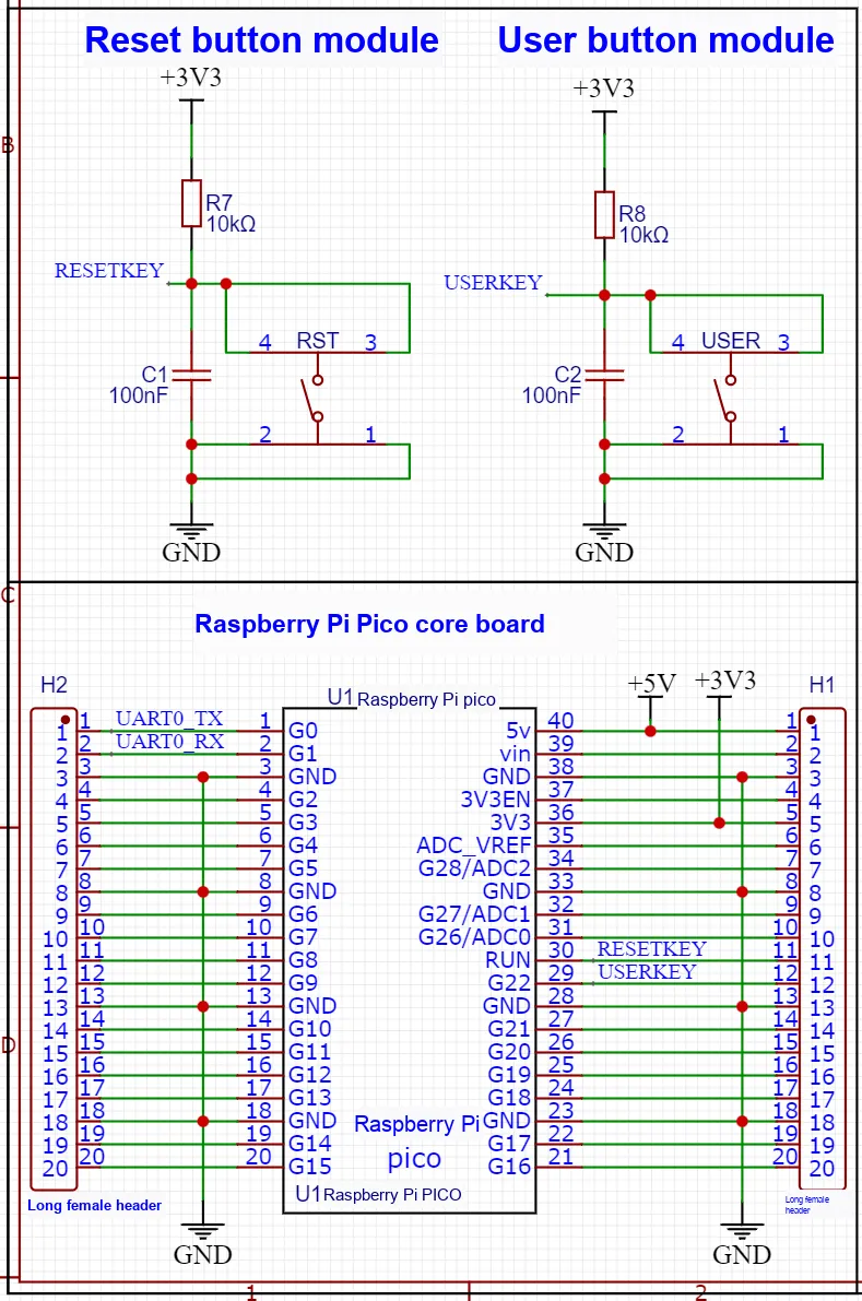
When the key is pressed, it is at a low level, so it is configured as falling-edge triggered:
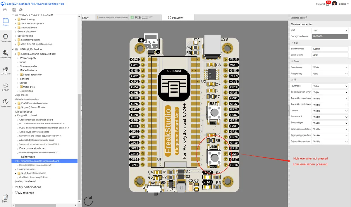
The following code can be found in the material package we provide in the elegance-devkit v1\Demo\55 Machine_Idle folder.
Sample code for the light sleep mode is as follows:
# Python env   : MicroPython v1.23.0
# -*- coding: utf-8 -*-
# @Time    : 2024/8/23 2:52 PM
# @Author  : Li Qingshui
# @File    : main.py
# @Description : Low-power experiment, using the machine.lightsleep() method to enter sleep mode

# ======================================== Import Modules ========================================

# Import the hardware module
import machine
from machine import UART
# Import time-related modules
import time

# ======================================== Global Variables ============================================

# ======================================== Functions ============================================

# Define the external interrupt handler function
def button_handler(pin: machine.Pin) -> None:
    """
    External interrupt handler function; after the button is pressed, toggles the LED state and prints a message.

    Args:
        pin (machine.Pin): The button instance that triggered the interrupt.

    Returns:
        None

    Raises:
        None
    """
    # Declare global variables
    global led, uart

    # Use the REPL to print debug information; it will not be output
    print("Button pressed!")
    # Use the serial port to print debug information
    uart.write("Button pressed!\r\n")

    # Toggle the LED
    led.toggle()

# ======================================== Custom Classes ============================================

# ======================================== Initialization ==========================================

# Create an LED object
led = machine.Pin(25, machine.Pin.OUT)

# Set GPIO22 as input and enable the pull-up resistor
button_pin = machine.Pin(22, machine.Pin.IN, machine.Pin.PULL_UP)
# Configure the external interrupt
button_pin.irq(trigger=machine.Pin.IRQ_FALLING, handler=button_handler)

# Create the serial port object, set the baud rate to 115200
uart = UART(0, 115200)
# Initialize the uart object with a baud rate of 115200, 8 data bits, no parity bit, and 1 stop bit
uart.init(baudrate  = 115200,
          bits      = 8,
          parity    = None,
          stop      = 1,
          tx        = 0,
          rx        = 1,
          timeout   = 100)

# ========================================  Main Program  ===========================================

# Power-on delay
time.sleep(3)
# Print debug information
print("FreakStudio : Using irq to wake up Pico of lightsleep mode")

# Enter lightsleep mode with a timeout of 100s
machine.lightsleep(100000)

# Delay 1s; otherwise, after the external interrupt wakes the CPU, the following statement would run first, and only then the external interrupt handler
time.sleep(1)
# On the Raspberry Pi Pico the REPL cannot reconnect, so this statement will not be shown in the terminal
print("Woke up from lightsleep mode.")
# Use the serial port to print debug information; this statement will be printed
uart.write("Woke up from lightsleep mode.\r\n")
Burn the code, connect to the remote terminal, and the output is as follows:
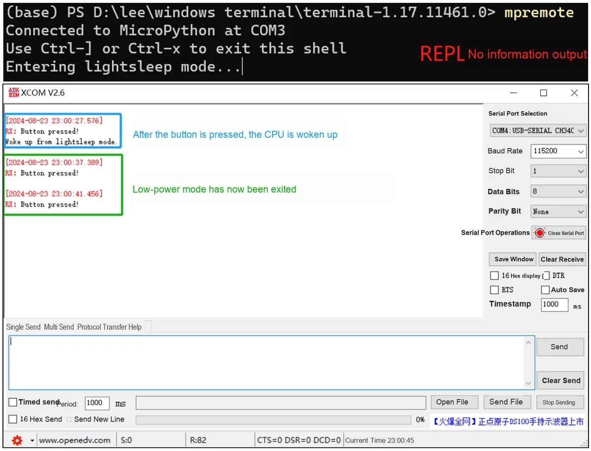
3.2 Application Experiment.mp4 43.3 MB
It can be seen that when we press the key, the external interrupt wakes up the CPU, the LED toggles between on and off, the serial port outputs debugging information, and the microcontroller exits the light sleep mode;Here, as we mentioned above, it is impossible to reconnect to the REPL after sleeping, and communication problems with the computer will occur after reinitialization.
Now we connect a USB power meter to Fengya No. 1 Board - Universal Compatible Expansion Board the USB port of Raspberry Pi Pico to compare the power consumption in the two modes:
3.3 Deep Sleep Mode Experiment
References
- 【WaveShare RP2040 Dual-Core Development Board】Instruction Set and Usage of MicroPython on RP2040
https://bbs.eeworld.com.cn/thread-1230340-1-1.html
- low power mode
https://docs.geeksman.com/esp32/MicroPython/esp32-micropython-deep-sleep.html
- micropython #2
https://github.com/ghubcoder/PicoSleepDemo/issues/2
- Deep sleeping the Raspberry Pico with Micropython
https://ghubcoder.github.io/posts/deep-sleeping-the-pico-micropython/
Version History
Version Number | Modifier | Time | Content |
v1.0.0 | Li Zisheng | 2025/09/19 | Initialize the document, based on MicroPython version v1.23.0. However, MicroPython version v1.26.0 should have fixed the issue with the low-power mode. At the same time, the deep sleep experiment has not been written yet. |