
Contents
- 1. Hardware Explanation
- 1.1 Introduction to WDT Watchdog Timer
- 1.2 Introduction to the WDT Peripheral in Raspberry Pi Pico
- 1.3 DS1232 External Watchdog Chip
- 2. Software Control Method
- 2.1 Constructor of machine.WDT
- 2.2 Other Methods of machine.WDT
- 3. Application Examples
- 3.1 Built-in Watchdog Experiment
- 3.2 Implementing Watchdog Experiments with Software Timers
- 3.3 Multi-threaded Implementation of Watchdog Experiment
- 3.4 External Watchdog Experiment
- References
- Appendix
- What should I do if the main.py file in MicroPython keeps running and restarting repeatedly?
- Version Record
1. Hardware Explanation
1.1 Introduction to WDT Watchdog Timer
1.1.1 Introduction to WDT Watchdog Timer
In a single-chip microcomputer system, as its operating environment is usually complex and vulnerable to interference from factors such as external electromagnetic fields, the following problems may arise:
- Register and memory data corruption: External electromagnetic interference may accidentally modify the data in registers or memory, affecting the normal execution of the program
- Program Pointer Error: The program pointer may point to an unintended memory location due to data errors or interference, causing the system to execute incorrect instructions.
- Fall into an infinite loop: If the program counter jumps to an incorrect location, the program may enter an endless loop that it cannot exit, causing the system to stall
- System stagnation: When a program gets stuck or fails to execute correct instructions, the entire system may fall into a stagnant state and be unable to perform the expected operations
To address these issues, the Watchdog Timer (WDT) plays the following key roles in the system. The Watchdog Timer (WDT) is a hardware timer used to monitor the operating status of the system. Its main function is to prevent the system from getting stuck in an infinite loop or a frozen state. When the system software is running normally, it needs to reset the Watchdog Timer periodically. If the system malfunctions and fails to reset the Watchdog Timer in time, the timer will trigger a system restart or other predefined actions to ensure that the system can return to a normal state.
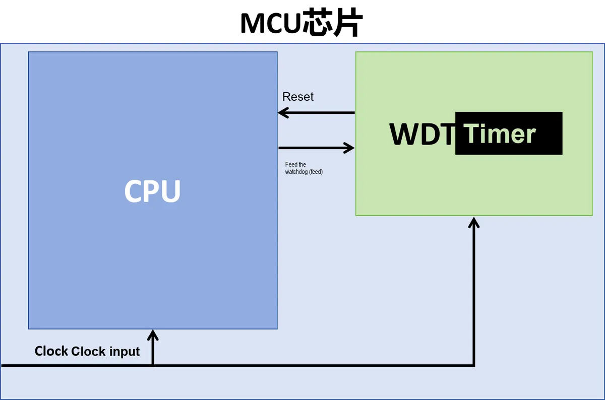
The basic working principle thereof is as follows:
- Start the watchdog timer: The core of the watchdog timer is a simple countdown timer, which is used to reset the microprocessor after a specific time interval. When the watchdog timer is enabled, it will start counting down.
- Periodic Reset: A normally running program needs to periodically reset the watchdog timer before its countdown completes (commonly referred to as "feeding the watchdog" or "kicking the watchdog"), which is typically achieved by calling the function that resets the watchdog in the main program loop or a timer.
- System reset: If the watchdog timer counts down to zero without being reset, it will usually trigger a system reset (reboot), which helps the system recover from an abnormal state.
In terms of working principle, watchdogs can be divided into the independent watchdog (IWDG) and the window watchdog (WWDG):
- Independent watchdog (
IWDG): The IWDG is a watchdog timer completely independent of the main processor, usually driven by an independent low-power oscillator (such as a 32kHz low-frequency crystal oscillator or an internal RC oscillator), which enables it to keep operating when the main processor malfunctions or the main clock fails; The IWDG is designed to be extremely simple and reliable, a reset will be generated when its counter counts down to 0. Once the IWDG is started, it generally cannot be stopped or disabled via software, and it is commonly used to prevent program runaway or infinite loops.
Example image missing
- Window Watchdog (
WWDG): The key feature of WWDG is a "window period", meaning that the watchdog timer must be reset within this specific time window; if the reset occurs too early or too late, the WWDG will trigger a system reset. This mechanism effectively prevents the program from getting stuck in an infinite loop or resetting the watchdog prematurely or belatedly. WWDG usually relies on the system main clock or other high-frequency clock sources, so it may fail to function properly if the system main clock malfunctions. It is typically used to prevent the program from executing outside the predetermined logic, such as completing before the ideal conditions are met or timing out beyond the maximum allowable duration.
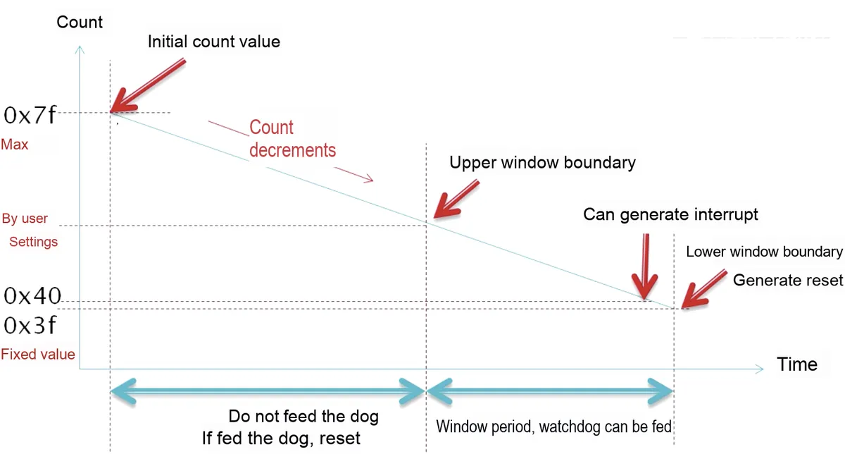
In terms of composition structure, watchdogs can be divided into built-in watchdog peripherals and external watchdog chips:
- Built-in Watchdog Peripheral (On-chip Watchdog Timer): The built-in watchdog is an internal component of the microcontroller (MCU), and it usually exists as a standard peripheral on the chip, which means that it shares the same clock and resources with other peripherals such as timers, UARTs, etc.
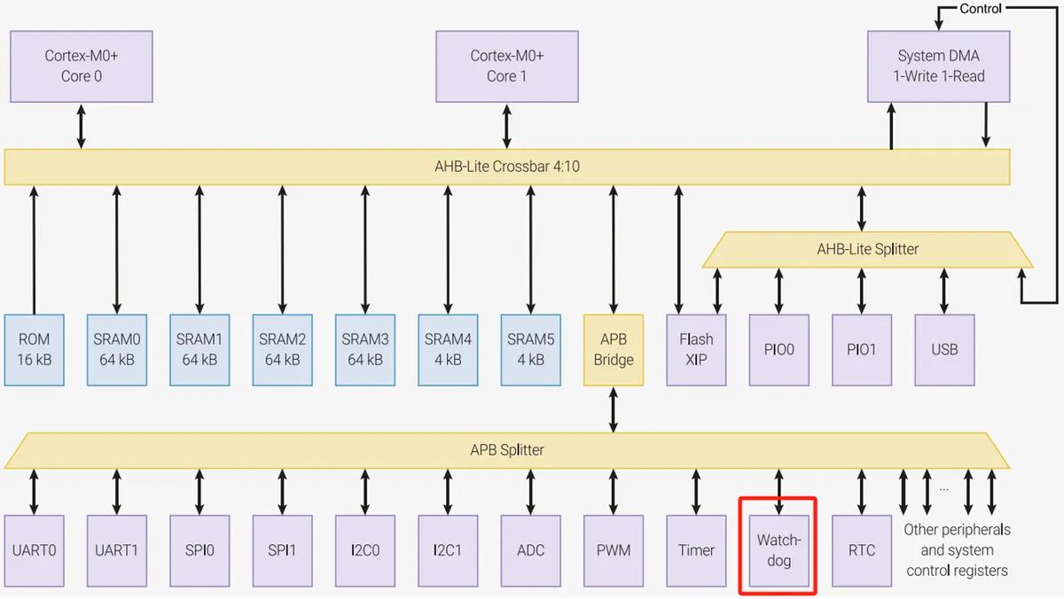
Built-in watchdog peripheral of the Raspberry Pi Pico - Easy to use: Since the watchdog timer is built-in, developers can directly configure and control it through the registers of the MCU without additional hardware or connections
- High integration level: The built-in watchdog features a very high level of integration, and can implement low-power monitoring through the internal clock and power management unit of the MCU.
- Limited by the faults of the MCU itself: If
MCU's main clock or other critical resources fail, the built-in watchdog may be affected. For example, ifthe MCUenters an unrecoverable fault state (such as main clock failure), the built-in watchdog may not work properly.
- External Watchdog Timer Chip: An external watchdog timer chip is an independent integrated circuit that connects to the MCU via GPIO or other interfaces, enabling it to function properly even when the MCU suffers a critical failure.
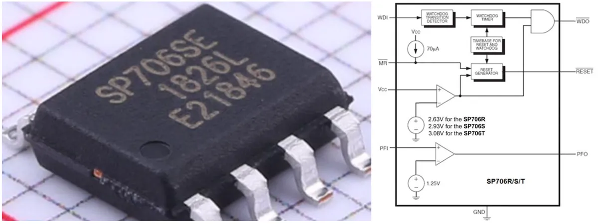
SP706 external watchdog chip, with a built-in watchdog timer and power monitoring function - High Reliability: Since the external watchdog chip operates independently, it can usually continue to monitor and perform reset operations when the MCU malfunctions. This independence makes it particularly critical in applications with stringent reliability requirements.
- High flexibility: External watchdog chips usually come with more configuration options and functions, such as more precise timing control, programmable timeout windows, and different reset options (e. g., hard reset or soft reset).
- Complexity and Cost: An external watchdog chip requires additional hardware circuits and connections, which increases the complexity and cost of the system. This may be a limiting factor in some cost-sensitive applications.
In terms of implementation methods, watchdogs can be divided into software watchdogs and hardware watchdogs:
- Software Watchdog: A software watchdog is implemented entirely via software code. It typically periodically checks the system status at the operating system or application level and triggers corresponding actions (such as system reset or alert). Developers periodically reset the software timer in the code to prevent it from timing out; if the software watchdog does time out, the system can trigger a specific response, such as a software reset or the execution of a fault handling routine.
- Dependency on the main processor: Since the software watchdog is implemented via software, it relies on the normal operation of the main processor and the operating system. In the event of a serious failure in core system functions such as clock or memory management, the software watchdog may fail to function properly.
- Flexibility: The software watchdog features high flexibility and can be configured and adjusted according to application requirements. Developers can set different timeout periods, alarm mechanisms, and even trigger different processing procedures under varying conditions.
- Complexity and Resource Consumption: A software watchdog consumes a certain amount of processor resources, which may affect system performance especially in systems with high real-time requirements; in addition, the logic and code for implementing a software watchdog may be relatively complex.
- Hardware Watchdog: A hardware watchdog is implemented by an independent hardware circuit, usually serving as a standalone peripheral in a microcontroller (MCU) or processor chip, or existing as an external separate chip. It is equipped with an independent timer that must be reset within a preset period, otherwise it will trigger a system reset or other predefined actions.
- Independence and Reliability: The hardware watchdog does not rely on the operation of the main processor and is usually driven by an independent clock source. Therefore, even if the main functions of the system fail, the hardware watchdog can still work properly, which makes it extremely reliable, especially in mission-critical systems.
- Low resource consumption: The hardware watchdog barely occupies any processor resources; the system only needs to periodically trigger the watchdog reset signal, which has minimal impact on system performance.
- Once enabled, it generally cannot be disabled: Many hardware watchdogs cannot be turned off via software after being started, which ensures that the system is always under monitoring, and this feature is particularly critical in mission-critical systems.
Here, when developing a project, it is recommended that you use the built-in watchdog timer peripheral and additionally equip an external watchdog chip: when the hardware of the MCU itself fails (such as power voltage fluctuation, clock failure, memory corruption, etc.), the built-in WDT may also be affected, making it unable to reset the system normally, while the external WDT can operate completely independently of the normal functions of the MCU, without being affected by the limitations of the MCU's internal resources.
Simply put, an external WDT provides an additional layer of security, enhancing the system's redundancy and reliability to prevent a single point of failure from crashing the entire system, ensuring that even in the worst-case scenario, the system can still safely reset and resume operation.
1.2 Introduction to the WDT Peripheral in Raspberry Pi Pico
The on-board RP2040 chip of the Raspberry Pi Pico has a built-in hardware watchdog timer (WDT) peripheral:
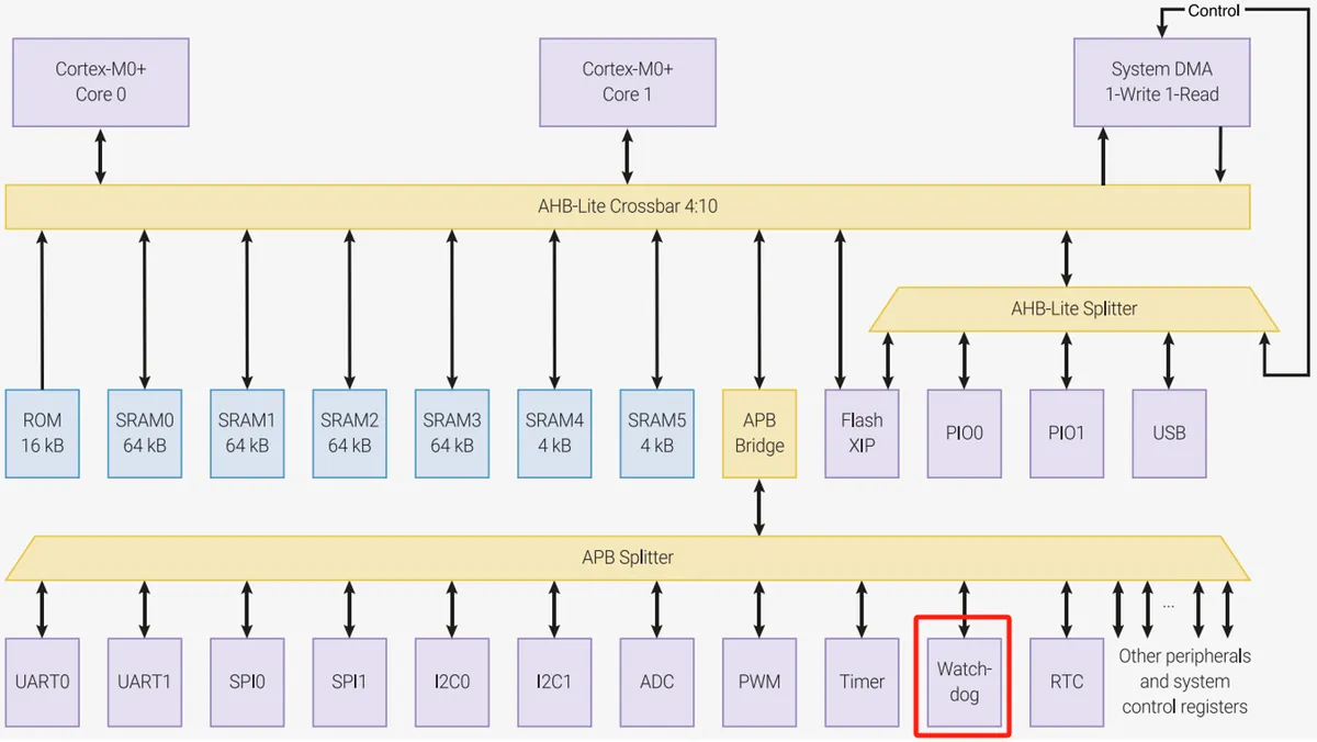
The watchdog timer of the RP2040 features a 24-bit counter with a maximum value of 0xFFFFFF (i. e. 16,777,215).
1.2.1 Watchdog Clock Input
In the RP2040 microcontroller, the reference clock used by the Watchdog Timer (WDT) clk_tick is driven by clk_ref:
- Ideally,
clk_refwill be configured to use a crystal oscillator clk_refis internally frequency-divided to generate a watchdog clockclk_tick, which is used to drive the timing function of the watchdog timer.
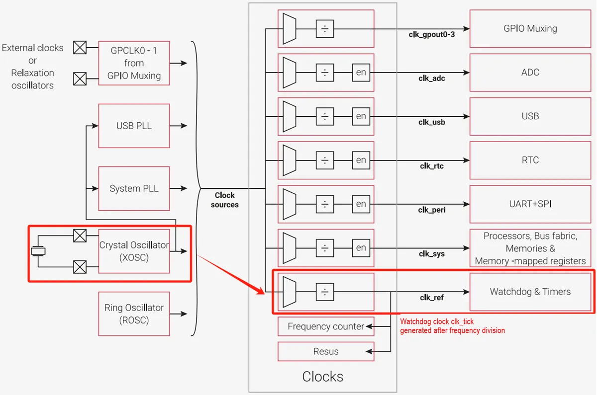
clk_tick typically has a period of 1 microsecond (μs), which means the watchdog timer counts at 1-microsecond intervals, enabling it to accurately monitor the operating status of the system.
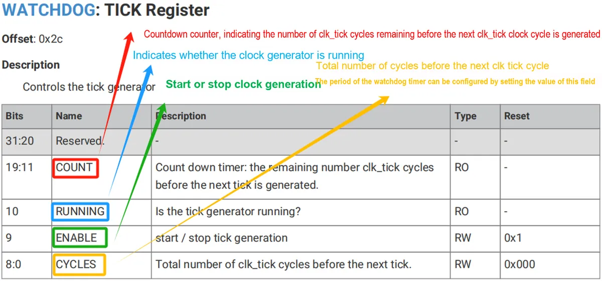
We can configure the TICK register to set the clock division ratio and adjust the time interval of the watchdog timer:
1.2.2 Reset of the Watchdog Timer
The watchdog timer is reset via the rst_n_run signal. When the digital core power supply (DVDD) is powered on and stable, and the RUN pin is at a high level, rst_n_run signal is activated, causing the watchdog timer to reset.
rst_n_run is a reset signal, which is closely related to the power management and reset control logic of the chip. Earlier when we introduced the Raspberry Pi Pico, we mentioned the basic concept of the power-on finite-state machine: the power-on finite-state machine of the RP2040 is responsible for releasing the reset state of each internal hardware module of the chip in a specific order, and this process ensures that each module is initialized in the correct sequence during startup, so as to avoid conflicts or errors during the reset period.
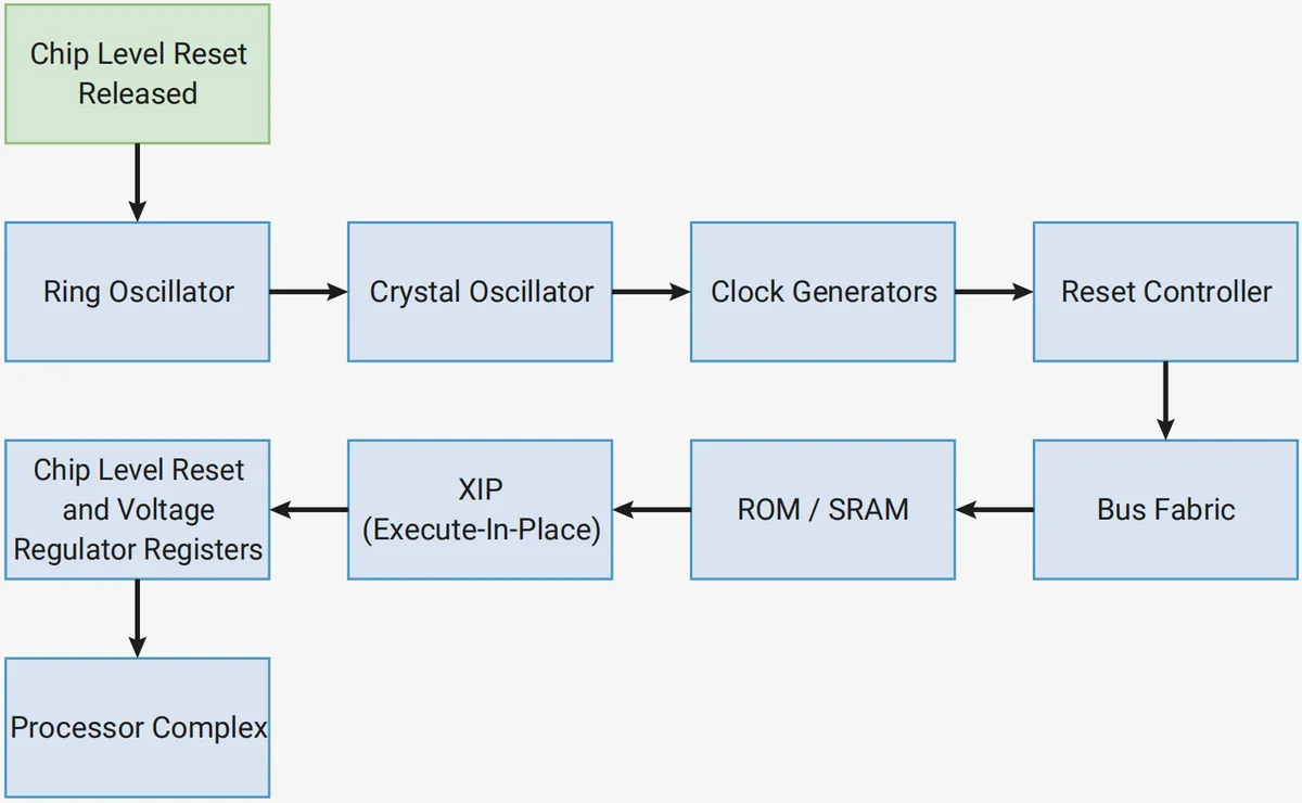
The reset of each module is controlled by the internal rst_n signal, and each module will generate a rst_done high-active reset completion signal after completing reset. The power-on finite-state machine waits for the rst_done signal of each module, and proceeds to the next module only after ensuring that all modules are correctly reset. After the power-on finite-state machine completes the reset operation for all modules, the rst_n_run signal is used to exit the specific reset state.This signal is typically used for modules that require initialization at startup but do not need to be reset during the power-on finite-state machine reset, such as ring oscillators, logic circuits in crystal oscillators, as well as clock dividers and watchdog timers that need to operate continuously.
1.2.3 Watchdog Counter
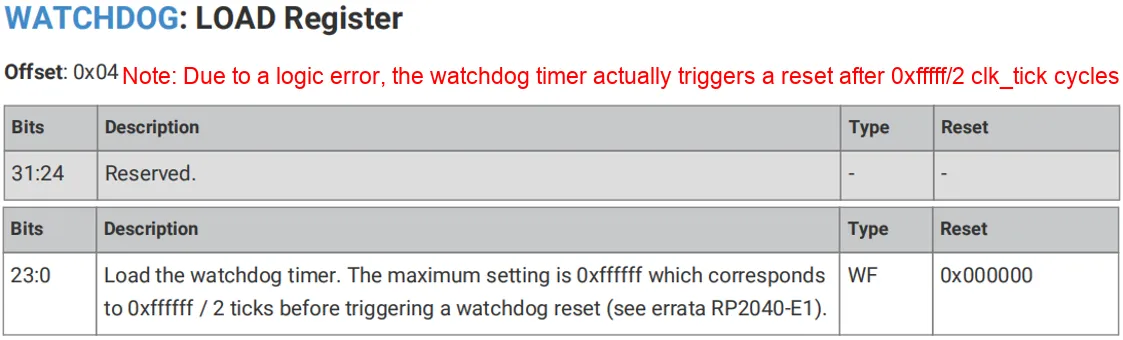
In the watchdog timer of the RP2040 microcontroller, the operation of the counter involves LOAD register and the CTRL register's TIME data bits:
LOADregister is used to set the initial value of the watchdog counter:
CTRL.TIMEThe data bits are used to display the current value of the watchdog counter:
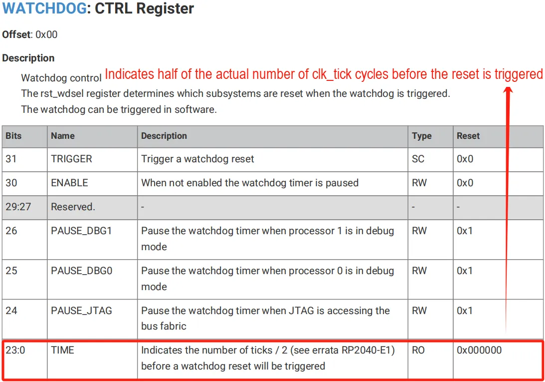
Here, it should be noted that due to a logic error (as mentioned in the RP2040-E1 errata), the watchdog counter is decremented twice in each clk_tick cycle, which means the actual countdown period is half of the expected value. Therefore, when the value of the LOAD register is set to 0xffffff (i. e., 16,777,215), the watchdog timer will actually trigger a reset after 0xffffff / 2 clk_tick cycles.
Since the period of a clk_tick is typically 1 microsecond (μs), the time corresponding to the maximum counter value is:
16,777,215/(2*1,000,000) s = 8.388 s = 8388 ms
This means that the timing range of the watchdog timer is approximately from 1 microsecond to 500 milliseconds.
Meanwhile, we can control the CTRL register's PAUSE_DBG1, PAUSE_DBG0 and PAUSE_JTAG bits to pause the watchdog timer when processor 0 and processor 1 enter debug mode or the JTAG debug interface is used to access the bus, so as to prevent the watchdog timer from interfering with the debugging process.
We can also access the REASON register to obtain the cause of the last reset:
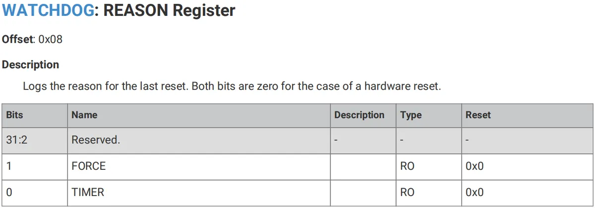
to determine whether the last reset was a forced reset triggered by the watchdog timer, or caused by a watchdog timer timeout or a hardware reset:
- When both bits in the register (
FORCEandTIMER) are 0, it indicates that the last reset was triggered by a hardware reset - If
FORCbit is 1, it indicates that the watchdog timer has issued a forced reset signal via theCTRLregister'sTRIGGERbit - If the
TIMERbit is 1, it indicates that the reset is caused by a watchdog timer timeout.
1.2.4 Scratch Registers and Magic Numbers
The watchdog timer of the RP2040 microcontroller includes eight 32-bit scratch registers, which can store information between soft resets of the chip:
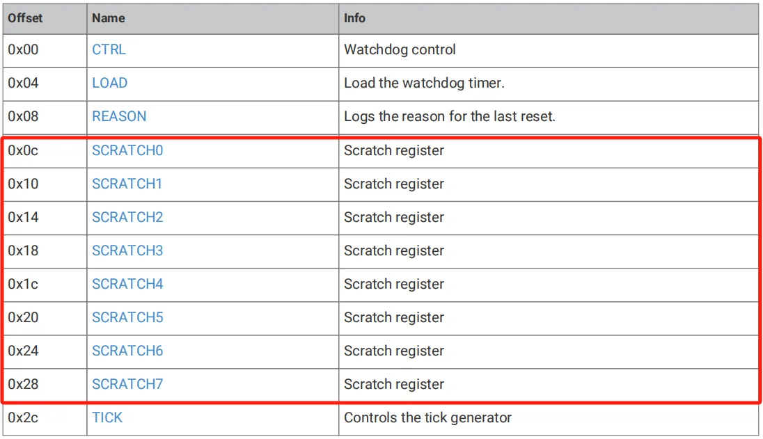

When the rst_n_run signal is triggered (for example, by toggling the RUN pin or powering on the digital core power supply DVDD again), these registers will be reset to their initial states.
In the case of non-power-on reset (Non-POR) or non-boot reset (Non-BOR), users can use these registers to specify a particular boot code. The Bootrom will check the specific "magic number" in these registers during startup, so as to determine whether to execute the user-defined boot code.
Here, a "magic number" refers to a special value used to verify data integrity, identify data formats, or confirm file structures:
- A magic number is used in the Scratch register of the watchdog timer to determine whether to execute the specific boot code
- This enables users to install their own boot handlers and skip the main boot sequence during non-power-on resets.
Wherein:
- Scratch 4: Magic Number for Storage
0xb007c0d3 - Scratch 5: stores the value obtained by XORing the entry point with the magic number
0xb007c0d3, which specifically is0x4ff83f2d - Scratch 6: Stack Pointer
- Scratch 7: Storage Entry Point
The Bootrom checks Scratch 4 and Scratch 5 for magic values: if these values match, the Bootrom clears Scratch 4 and transfers control to the specified code segment; if the magic values do not match, the Bootrom will not execute the user-defined boot code, and the system will boot according to the default boot sequence. Through this mechanism, users can control the execution of specific code or perform system debugging during system startup, which is very useful for system testing and debugging.
1.3 DS1232 External Watchdog Chip
1.3.1 Introduction to the DS1232 Chip
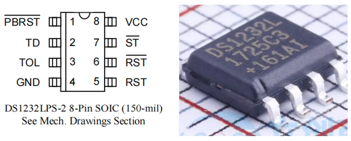
DS1232 is a microprocessor monitor chip launched by Maxim.
Its main functions are as follows:
- Provides a watchdog timer function: if the
MCUfails to input a pulse signal to theST(strobe) pin within the specified time, the chip will trigger a reset. - Provides power supply voltage monitoring and reset functions: when the
VCCsupply voltage is lower than the reset threshold (approximately 4.37V or 4.62V, depending on the model), the chip automatically outputs a reset signal (RST). - Provides a manual reset interface: via the
PBRSTpin, users can connect an external button to manually trigger a reset.
Therefore, the DS1232 is commonly used in scenarios requiring high reliability such as microcontrollers and embedded systems.
1.3.2 Introduction to Pins of DS1232 Chip
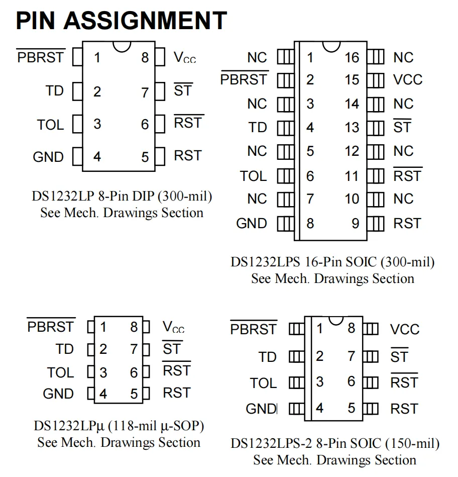
DS1232 The pin functions of the chip are shown in the following table:
Pin Name | Function Description |
VCC | Power Input (+ 5V) |
GND | Power Ground |
RST counter | Reset output (active low, connected to MCU RESET pin) |
RST | Reset Output (Active High, Optional) |
ST | Watchdog refresh signal input (high-to-low transition) |
PBRST | External manual reset input (low-level triggered, internal debounce) |
TOL | Power supply threshold selection (connect to GND = 4.75V, connect to VCC = 4.5V) TD Watchdog Timeout Selection (the wiring determines 150ms/600ms/1.2s) |
TD | Watchdog timeout selection (150ms/600ms/1.2s configurable via wiring) |
NC | NC (No function, for SOIC package) |
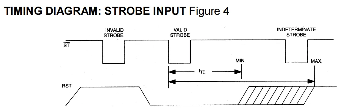
Chip DS1232 requires a continuous series of pulses to be input to the ST pin during system operation; the time interval between these pulses is set by the TD pin. If the pulse interval exceeds the set value of the TD pin, the chip will output a reset pulse to the RST pin and the RST# pin to reset the microcontroller. This function is commonly referred to as a watchdog, and the series of pulses input to the watchdog is called "feeding the dog".
1.3.3 Internal Structure and Working Principle of the DS1232 Chip
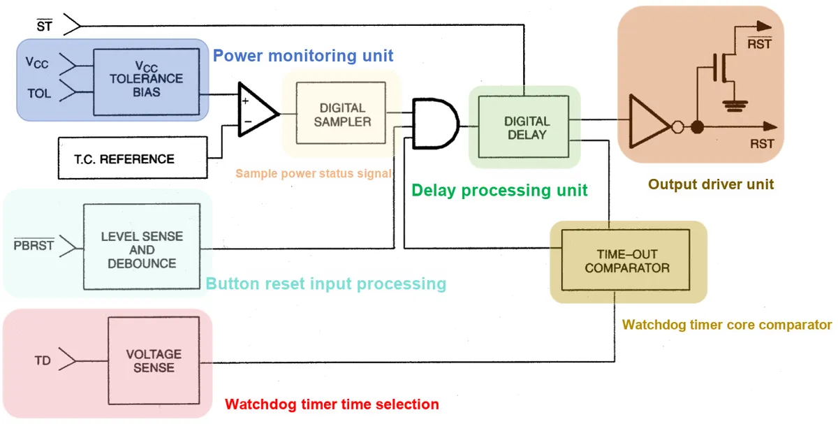
DS1232 The internal structure of the chip is shown in the figure, which mainly consists of the following parts:
- Power Monitoring Unit (VCC Comparator + Reference + TOL): Detects whether the power supply voltage is normal.
- Principle: Compare the power supply voltage VCC with the internal temperature-compensated reference voltage, and the threshold is determined by the
TOLpin:TOL= GND: Threshold: 4.75VTOL= VCC: Threshold: 4.5V
- Trigger Condition: When
VCCdrops below the threshold, the output signal is sent to the subsequent logic to force a system reset.
- Principle: Compare the power supply voltage VCC with the internal temperature-compensated reference voltage, and the threshold is determined by the
- Sampling Power Status Signal (Digital Sampler): It performs digital sampling on the output of the power comparator to filter out instantaneous interference, so as to prevent false reset caused by transient fluctuations or noise of the power supply. Reset is triggered only when the power supply voltage continuously stays below the threshold.
- Button Reset Input Processing (Level Sense and Debounce, PBRST): Manually trigger a system reset.
- Principle:
PBRSTpin is connected to the button and is triggered at low level.- The internal circuit is equipped with debounce function, which prevents multiple erroneous resets caused by the jitter of mechanical buttons.
- After the key is released, the output reset signal will still be maintained for 250ms to ensure reliable reset of the MCU.
- Principle:
- Watchdog Timer Time Selection (Voltage Sense, TD)
- Function: Set the timeout period of the watchdog timer.
- Principle: Selection via the connection mode of the TD pin:
TD=GND:150msTD= Floating: 600msTD=VCC:1.2s
- The MCU must provide the ST pin with a falling edge (dog feeding) within this timeframe; otherwise, a reset will be triggered.
- Watchdog Timer Core Comparator (Time-Out Comparator): It determines whether the MCU feeds the watchdog within the specified time.
- Principle:
- If there is no falling edge at the ST input within the set timeout period, the MCU is considered to be hung up, and a reset request is output.
- If there is a valid transition of ST → the timer is cleared and restarted.
- Principle:
- Delay Processing Unit (Digital Delay): Ensures the minimum duration of the reset signal.
- Principle: Regardless of whether the reset signal is triggered by power supply abnormality, key reset, or watchdog timeout, the Digital Delay will ensure that the reset output lasts for at least 250ms, preventing the MCU from abnormal startup due to excessively short reset duration.
- Output Driver Unit (Output Driver, RST/RST̅): Outputs the reset control signal to the MCU.
- Principle:
- Provides two complementary outputs:
- RST (active low)
- RST̅(active high)
- It is convenient for users to select the reset polarity suitable for the MCU.
- Provides two complementary outputs:
- Principle:
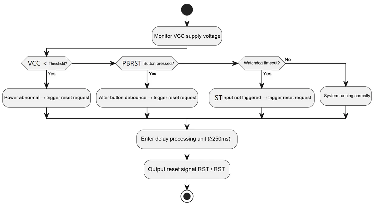
DS1232 monitors the VCC voltage via the power supply monitoring unit to detect whether it is lower than the set threshold; once an abnormality is detected, it immediately outputs a reset signal, and maintains a reset delay of at least 250ms after the power supply is restored to ensure system stability. Meanwhile, this chip supports key reset input, and will generate a reset pulse of no less than 250ms after internal debouncing. In addition, it has a built-in watchdog timer: if no trigger pulse from the processor is received within the set timeout period (150ms/600ms/1.2s), it will determine that the system is halted and automatically send out a reset signal.All reset requests pass through the delay processing unit and are then output uniformly by the output driver RST / RST̅, to ensure that the microprocessor receives reliable reset control.
1.3.4 Reference Application Circuits and Notes
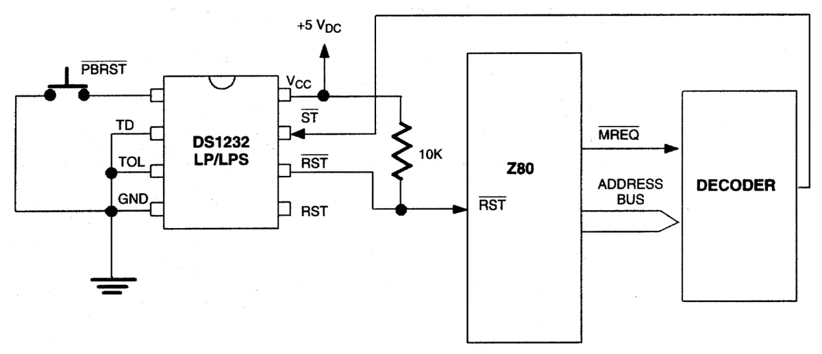
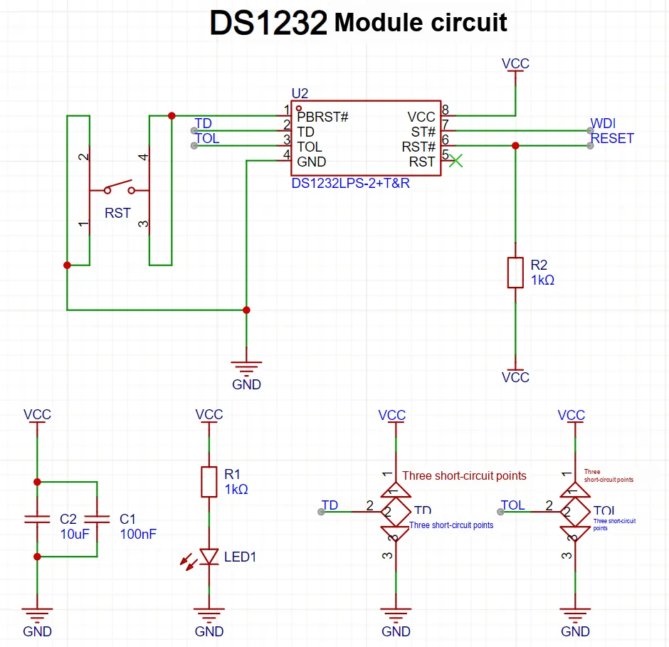
The figure above shows the peripheral circuit of the DS1232 chip, which monitors the undervoltage of VCC and generates a reset (RST high level, /RST low level) in case of abnormality, with a built-in watchdog at the same time:
- The MCU must perform watchdog feeding (generate a high-to-low pulse) on the ST pin within the time window set by the TD pin; otherwise, the module will trigger a reset of at least 250ms. PBRST is an external button reset input, and pressing it will force a reset.
- In the diagram, C1/C2 serve as power supply decoupling components, the R1+ LED combination indicates the presence of power, R2 acts as a pull-up resistor for /RST (pulling the open-drain /RST high), and TD/TOL are used to select the timeout and voltage tolerance thresholds via a tri-state solder jumper or DIP switch.
Note that the DS1232 is designed for 5V operation. If the IO level standard of the MCU in use is 3.3V, ensure proper level compatibility or select a 3.3V monitoring chip to avoid damaging the MCU.
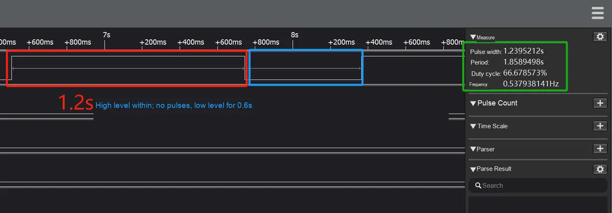
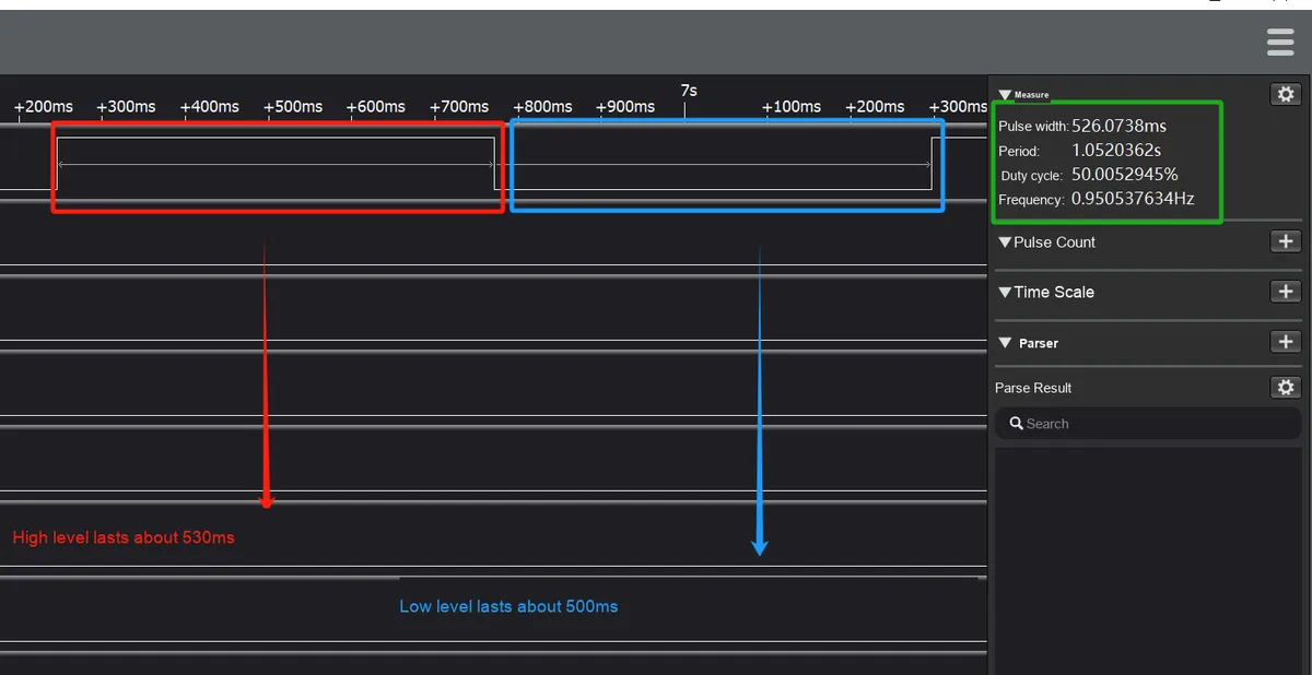
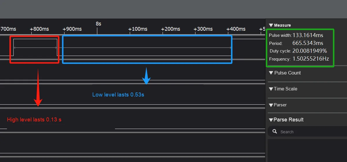
The following are the results of our module test. After powering on the module, we connected Channel 0 of the logic analyzer to the RST interface of the watchdog module:
When TD is connected to VCC, the pulse interval shall not be greater than 1.2 seconds, and a square wave with an input frequency of 2 Hz is recommended:
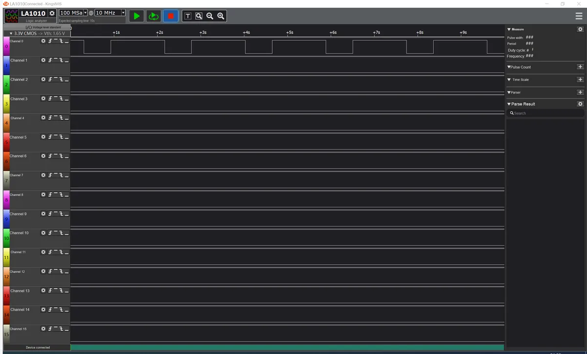
TD When floating, the pulse interval shall not exceed 600 ms, and a square wave with an input frequency of 10 Hz is recommended:
TD When connected to GND, the pulse interval shall not exceed 0.15 seconds, and a square wave with an input frequency of 30Hz is recommended:
Here we can see that in practical applications, the watchdog feeding frequency needs to be higher than that specified in the chip datasheet. This is due to factors such as the internal timing accuracy error, sampling delay, and pulse width requirements of the DS1232, which make it highly likely to fail if the watchdog is strictly fed according to the theoretical limit. Therefore, in engineering practice, it is recommended to set the watchdog feeding period to 1/2 of the timeout period or even shorter.
In the provided datasheet, we can also see that the timing accuracy is approximately −58.33% / + 66.67%(relative to the typical value):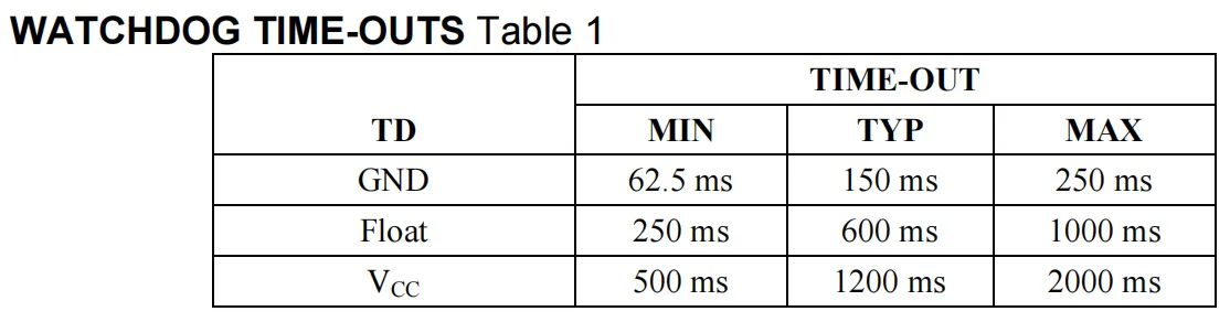
- GND gear: Typical value: 150 ms; minimum value: 62.5 ms (87.5 ms less than the typical value, which is approximately −87.5/150 = −58.33%); maximum value: 250 ms (100 ms greater than the typical value, which is approximately + 100/150 = + 66.67%).
- Float gear: Typical 600 ms, minimum 250 ms (difference 350 ms, approx. −58.33%), maximum 1000 ms (difference 400 ms, approx. + 66.67%).
- VCC Range: Typical 1200 ms, minimum 500 ms (difference of 700 ms, approx. −58.33%), maximum 2000 ms (difference of 800 ms, approx. + 66.67%).
2. Software Control Method
2.1 Constructor of machine.WDT
The constructor of the machine.WDT class is as follows:
class machine.WDT(id=0, timeout=5000)
Construct a WDT watchdog object with the given parameters; once started, the WDT cannot be stopped or reconfigured.
The parameters are defined as follows:
- id : Specifies the instance ID of the WDT. For most implementations, this parameter is fixed, typically 0, and it can be used to select a specific WDT instance in systems that support multiple watchdog timers.
- timeout: Sets the timeout period of the watchdog (unit: milliseconds). The timeout period must be specified during initialization. Once created, the timeout period cannot be changed, and the WDT cannot be stopped. For rp2040 devices, the maximum timeout period is 8388 milliseconds.
2.2 Other Methods of machine.WDT
The machine.RTC class has other methods as well:
Method | Description |
WDT.feed() | Feed the watchdog to prevent it from timing out and resetting the system. Applications should place this call after ensuring that the system is operating properly. |
3. Application Examples
3.1 Built-in Watchdog Experiment
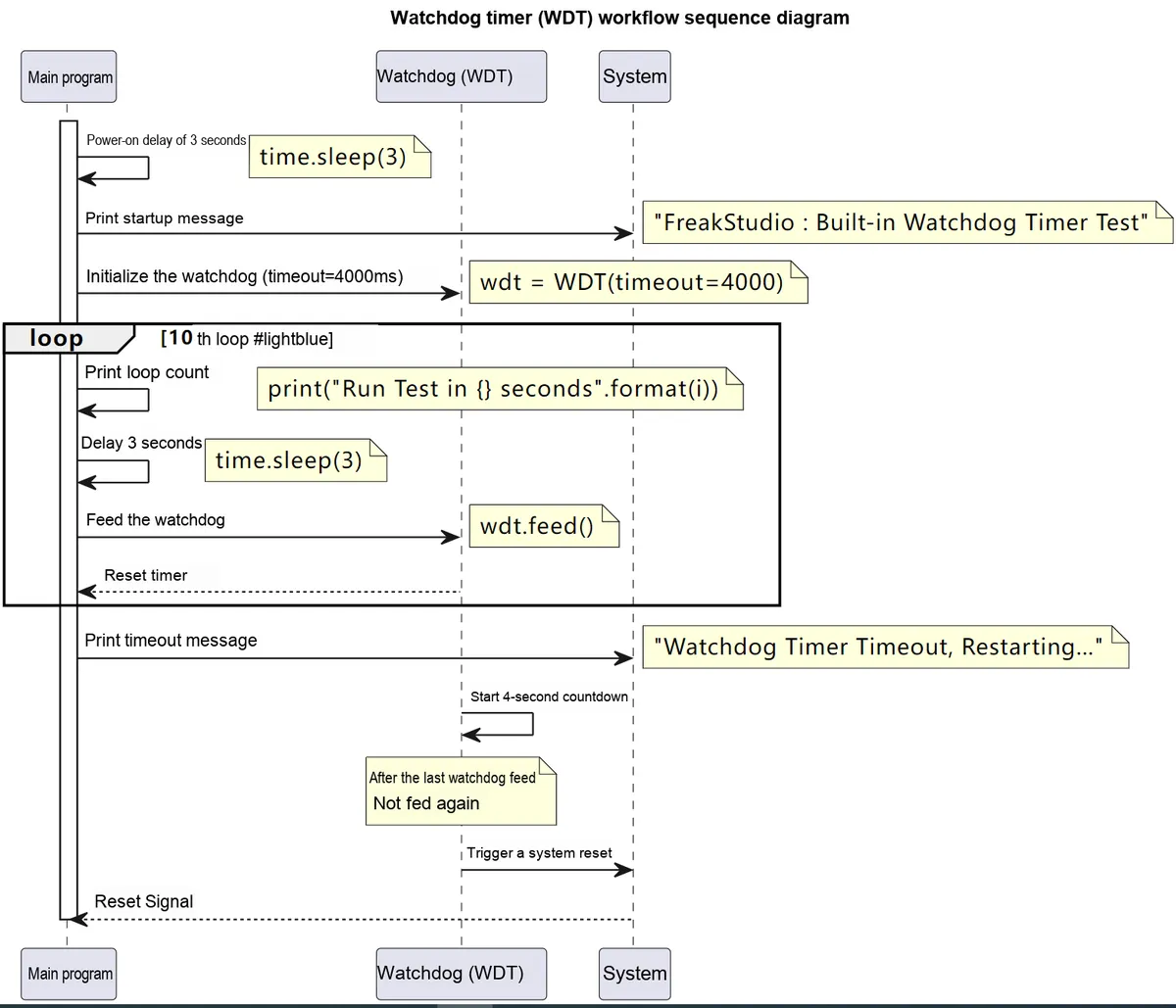
In the following code, we create a WDT object and set its timeout to 4 seconds (note that the timeout must not be less than approximately 2 seconds; if the timeout is set too short, the device will keep restarting continuously once the watchdog takes effect, making it impossible to flash programs or establish remote connections), which means that if the feed () method is not called within 2 seconds, the WDT will trigger a system restart.
Then a 30-second loop starts: in each iteration, the program prints the current test time, delays for 3 seconds, and then calls the feed () method to feed the watchdog to prevent the WDT from timing out. After 10 consecutive iterations, the loop is exited, the watchdog is no longer fed, and the device will reset shortly after.
The following code can be found in the material package we provide, in the elegance-devkit v1\Demo\52 WDG_Hardware folder.
The sample code is as follows:
# Python env   : MicroPython v1.23.0
# -*- coding: utf-8 -*-
# @Time    : 2024/8/15 3:12 PM
# @Author  : Li Qingshui
# @File    : main.py
# @Description : WDT watchdog timer class experiment, using the Pico's built-in watchdog peripheral

# ======================================== Import Modules ========================================

# Import hardware-related modules
from machine import WDT
# Import time-related modules
import time

# ======================================== Global Variables ============================================

# ======================================== Functions ============================================

# ======================================== Custom Classes ============================================

# ======================================== Initialization ==========================================

# Power-on delay of 3 s
time.sleep(3)
# Print debug information
print("FreakStudio : Built-in Watchdog Timer Test")

# Initialize the watchdog object
# Set the watchdog timer timeout to 4 seconds
wdt = WDT(timeout=4000)

# ========================================  Main Program  ===========================================

# Feed the watchdog 10 times in a loop
for i in range(10):
    # Print debug information
    print("FreakStudio : Run Test in {} seconds".format(i))
    # Delay 3s
    time.sleep(3)
    # Feed the watchdog
    wdt.feed()

# After running for 37 s, the watchdog timer times out and restarts
print("FreakStudio : Watchdog Timer Timeout, Restarting...")
The overall Sequence Diagram of the operation is shown as follows:
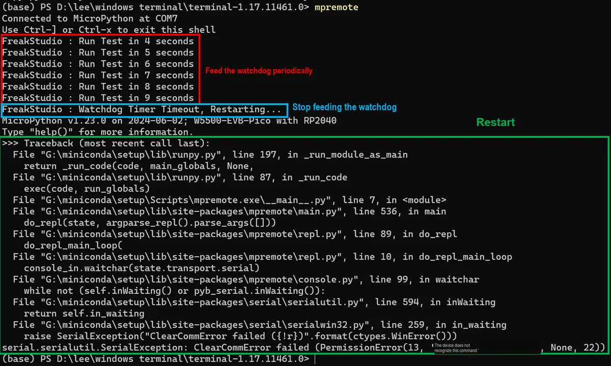
Burn the code, open the terminal, and use mpremote to connect to the Raspberry Pi Pico, with the following output:
3.1 Application Experiment.mp4 899 KB
It can be seen that after the dog feeding is stopped, the watchdog timer will restart the device once the timeout period is reached.
3.2 Implementing Watchdog Experiments with Software Timers
In the example in the previous section, we used the built-in watchdog of the Raspberry Pi Pico to monitor the operating status of the system and restart the device, but it can be found in the documentation that the built-in watchdog also has some drawbacks:
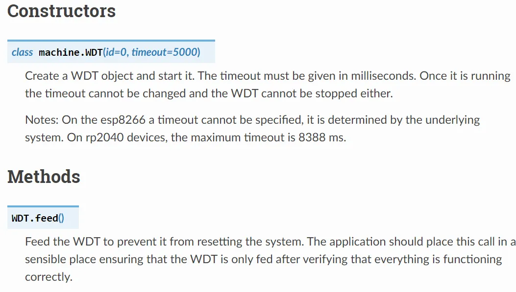
It mainly focuses on the following two parts:
- Fixed timeout period: Once the timeout period is configured, it cannot be adjusted during operation; meanwhile, once the timeout elapses without a watchdog refresh, the hardware will immediately trigger a reset, with no option for delay or other processing.
- Lack of scalability: The hardware watchdog is only responsible for monitoring and resetting, and cannot record status, perform log processing or attempt system recovery before resetting.
In practical applications, when a program encounters a runaway or abnormal situation, we usually first attempt to fix the problem through recovery operations, such as reinitializing key modules, restarting partial functions, or performing log recording. The software watchdog is designed precisely for this purpose; in a microcontroller system, the software watchdog can be implemented by means of a timer or a counter.The principle is to use a timer or counter as the timing trigger source. The timer counts down continuously, and if it is not reloaded or "kicked" within the set time, the system is considered to have fallen into an infinite loop or become unresponsive, thus triggering the watchdog function, such as system reset or executing other safety operations.
In the code we provide below, we implement a multi-functional software watchdog based on timers, whose main features include:
- Flexible timeout settings and reset delay: The software watchdog is implemented based on a timer, whose timeout duration can be configured and dynamically adjusted according to actual needs; meanwhile, a delay time can be set before the reset is triggered to reserve time for system recovery operations.
- Actively stoppable: the watchdog timer can be stopped by calling the
stop ()method, which facilitates temporarily disabling the watchdog protection in scenarios such as system maintenance and upgrade. - Flexible parameter settings: Users can configure the allowed number of consecutive watchdog timeouts, whether to enable debug mode, and the delay time before reset triggering.
- Flexible function extension: Users can implement status recording and logging, trigger condition judgment, and recovery operation mechanisms by passing in a custom function:
- Status Recording and Logs: Supports registration of status recording callback functions, which record the current status, timestamp and failure count when a fault occurs, to facilitate subsequent troubleshooting.
- Trigger condition judgment: Whether to allow the reset to be triggered can be determined through a custom trigger condition judgment function. For example, in some fault scenarios, recovery can be attempted first instead of performing an immediate reset.
- Recovery Operation Mechanism: When a program runaway is detected, an attempt can first be made to invoke recovery operations (such as reconnecting to the network, restarting partial functions, etc.), and the reset will only be triggered finally after the recovery fails, which better meets actual requirements.
- Debugging and Performance Monitoring: Using a timing decorator can count the execution time of the watchdog callback function, which helps to understand the real-time system performance and conduct optimization; in addition, after the debugging mode is enabled, detailed status information and execution logs will be output, facilitating developers to monitor the system status and fault response process in real time.
It has the following methods and properties:
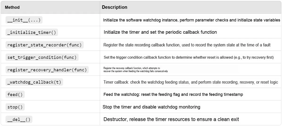
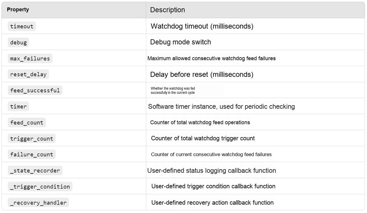
The code for the custom software watchdog class is as follows:
# Allocate the emergency exception buffer (must be placed before all interrupt code)
micropython.alloc_emergency_exception_buf(100)

# Software watchdog class
class SoftwareWatchdog:
    """
    Software watchdog class, implementing watchdog functionality using MicroPython's Timer.
    This class encapsulates timer-based watchdog logic, supporting timeout detection, feeding operations, state recording, trigger condition checking and recovery operations.
    By registering callback functions, users can customize the state recording, trigger condition and recovery operation logic.

    Attributes:
        timeout (int): Watchdog timeout, in milliseconds (default 4000 ms).
        debug (bool): Whether to enable debug mode (enabled by default).
        max_failures (int): Maximum number of consecutive feeding failures (default 1).
        reset_delay (int): Delay before triggering a reset, in milliseconds (default 3000 ms).
        feed_successful (bool): Feed flag, indicating whether the watchdog was fed successfully.
        timer (Timer): Software timer instance, used to periodically check the feeding status.
        feed_count (int): Counter of the number of feedings.
        trigger_count (int): Counter of the number of watchdog triggers.
        failure_count (int): Counter of consecutive feeding failures.
        _state_recorder (callable): User-defined state recording callback function.
        _trigger_condition (callable): User-defined trigger condition callback function.
        _recovery_handler (callable): User-defined recovery action callback function.

    Methods:
        __init__(self, timeout: int = 4000, debug: bool = True, max_failures: int = 1, reset_delay: int = 3000) -> None:
            Initialize the software watchdog instance.

        _initialize_timer(self) -> None:
            Initialize the timer and set the callback function.

        register_state_recorder(self, recorder: callable[[], None]) -> None:
            Register the status recording callback function.

        set_trigger_condition(self, condition: callable[[], bool]) -> None:
            Set the trigger condition callback function.

        register_recovery_handler(self, handler: callable[[], bool]) -> None:
            Register the recovery action callback function.

        _watchdog_callback(self, t: Timer) -> None:
            Timer callback function. Checks whether the watchdog was fed in time, and also records status and checks the condition to decide whether to trigger a reset.

        feed(self) -> None:
            Feed the watchdog and reset the feed flag.

        stop(self) -> None:
            Stop the watchdog timer.

        __del__(self) -> None:
            Destructor, ensures the timer resources are released.
    """
    def __init__(self, timeout: int = 4000, debug: bool = True, max_failures: int = 1, reset_delay: int = 3000) -> None:
        """
        Initialize the software watchdog.

        Args:
            timeout (int): Watchdog timeout, in milliseconds (default 4000 ms).
            debug (bool): Whether to enable debug mode (enabled by default).
            max_failures (int): Maximum number of consecutive feeding failures (default 1).
            reset_delay (int): Delay before triggering a reset, in milliseconds (default 3000 ms).

        Returns:
            None

        Raises:
            ValueError: If the parameters timeout, max_failures, or reset_delay are not positive integers, or debug is not a boolean.
        """
        # Check the entry parameters
        if not isinstance(reset_delay, int) or reset_delay <= 0:
            raise ValueError("reset_delay must be a positive integer")

        if not isinstance(timeout, int) or timeout <= 0:
            raise ValueError("timeout must be a positive integer")

        if not isinstance(max_failures, int) or max_failures <= 0:
            raise ValueError("max_failures must be a positive integer")

        if not isinstance(debug, bool):
            raise TypeError("debug must be a boolean value")

        # Set the timeout
        self.timeout = timeout
        # Set the debug mode
        self.debug = debug
        # Set the maximum number of failures
        self.max_failures = max_failures
        # Set the reset delay time
        self.reset_delay = reset_delay

        # Initialize the feed flag to False
        self.feed_successful = False
        # Initialize the software timer
        self.timer = Timer(-1)

        # Initialize the feed count
        self.feed_count = 0
        # Initialize the watchdog trigger count
        self.trigger_count = 0
        # Initialize the consecutive feed failure count
        self.failure_count = 0

        # Initialize the user-defined status recording function to None
        self._state_recorder = None
        # Initialize the user-defined trigger condition function to None
        self._trigger_condition = None
        # Initialize the recovery action callback function to None
        self._recovery_handler = None

        # Initialize the timer
        self._initialize_timer()

    def _initialize_timer(self) -> None:
        """
        Initialize the timer and set the callback function.

        Args:
            None

        Returns:
            None
        """
        # Initialize the timer, set the period and callback function
        self.timer.init(period=self.timeout, mode=Timer.PERIODIC, callback=lambda t: schedule(self._watchdog_callback, t))

    def register_state_recorder(self, recorder: callable[[], None]) -> None:
        """
        Register the status recording callback function.

        Args:
            recorder (callable): Callback function with no parameters and no return value, used to record status

        Returns:
            None

        Raises:
            TypeError: If the parameter recorder is not of callable type.
        """
        # Check whether recorder is a callable object
        if not callable(recorder):
            raise TypeError("State recorder must be callable")

        # Set the status recording callback function
        self._state_recorder = recorder

    def set_trigger_condition(self, condition: callable[[], bool]) -> None:
        """
        Set the trigger condition callback function.

        Args:
            condition (callable): Callback function with no parameters that returns bool; returning True means a restart is allowed to trigger.

        Returns:
            None

        Raises:
            TypeError: If the parameter condition is not of callable type.
        """
        # Check whether condition is a callable object
        if not callable(condition):
            raise TypeError("Trigger condition must be callable")

        # Set the trigger condition callback function
        self._trigger_condition = condition

    def register_recovery_handler(self, handler: callable[[], bool]) -> None:
        """
        Register the recovery action callback function.

        Args:
            handler (callable): Callback function with no parameters that returns a value, used to perform the recovery action; a return value of True means the recovery action succeeded, False means it failed.

        Returns:
            None

        Raises:
            TypeError: If the parameter handler is not of callable type.
        """
        # Check whether handler is a callable object
        if not callable(handler):
            raise TypeError("Recovery handler must be callable")

        # Set the recovery action callback function
        self._recovery_handler = handler

    # Use the @timed_function decorator to measure the run time of the SoftwareWatchdog._watchdog_callback method
    @timed_function
    def _watchdog_callback(self, t: Timer) -> None:
        """
        Timer callback function. Checks whether the watchdog was fed in time, and also records status and checks the condition to decide whether to trigger a reset.

        Args:
            t (Timer): Timer object (passed in automatically by Timer).

        Returns:
            None

        Raises:
            Exception: If an error occurs while executing the status recording callback function.
            Exception: If an error occurs while executing the recovery action callback function.
            TypeError: If the return value of the recovery action callback function is not of boolean type.
            Exception: If an error occurs while executing the trigger condition callback function.
        """

        # Read the feed flag atomically
        irq_state = disable_irq()
        feed_flag = self.feed_successful
        enable_irq(irq_state)

        # Check whether the watchdog was fed in time
        if not feed_flag:
            # Increase the consecutive failure count
            self.failure_count += 1
            # Increase the trigger count
            self.trigger_count += 1

            # If debug mode is on, print the trigger information
            if self.debug:
                print("[Watchdog] Triggered ({} failures, {} total triggers)".format(
                    self.failure_count, self.trigger_count))

            # Execute status recording (if registered)
            if self._state_recorder:
                try:
                    self._state_recorder()
                except Exception as e:
                    if self.debug:
                        print("[Error] Failed to record state:", str(e))

            # Check whether the consecutive failure count has reached the maximum
            if self.failure_count >= self.max_failures:

                # Flag indicating whether the recovery action succeeded
                recovery_successful = False

                # Try the recovery action
                if self._recovery_handler:
                    try:
                        if self.debug:
                            print("[Watchdog] Attempting recovery...")
                        # Try the recovery action
                        recovery_successful = self._recovery_handler()
                        # Check whether recovery_successful is a bool variable
                        if not isinstance(recovery_successful, bool):
                            raise TypeError("Recovery handler must return a boolean value")
                    except Exception as e:
                        if self.debug:
                            print("[Error] Recovery handler failed:", str(e))

                # Check whether the recovery action succeeded
                if recovery_successful:
                    # Reset the consecutive failure count
                    self.failure_count = 0
                    # Reset the should-trigger flag
                    self.should_trigger = False
                    if self.debug:
                        print("[Watchdog] Recovery successful, resetting failure count...")
                else:
                    # If recovery failed, check the trigger condition

                    # Trigger by default
                    should_trigger = True
                    # Check whether the trigger condition is registered
                    if self._trigger_condition:
                        try:
                            # Execute the trigger condition check
                            should_trigger = self._trigger_condition()
                        except Exception as e:
                            if self.debug:
                                print("[Error] Trigger condition check failed:", str(e))
                            # Trigger by default
                            should_trigger = True

                    # If the trigger condition is met, trigger a reset
                    if should_trigger:
                        if self.debug:
                            print("[Watchdog] Max failures reached, resetting system after %d ms..." %(self.reset_delay))
                        # Create a one-shot timer that performs the reset after the specified delay
                        self.reset_timer = Timer(-1)
                        self.reset_timer.init(period=self.reset_delay, mode=Timer.ONE_SHOT, callback=lambda t: reset())
        else:
            # Reset the consecutive failure count
            self.failure_count = 0

            # Atomic reset
            irq_state = disable_irq()
            # Reset the feed flag
            self.feed_successful = False
            enable_irq(irq_state)

    def feed(self) -> None:
        """
        Feed the watchdog and reset the feed flag.

        Args:
            None

        Returns:
            None
        """
        irq_state = disable_irq()
        self.feed_successful = True
        # Increase the feed count
        self.feed_count += 1
        enable_irq(irq_state)

        # If debug mode is on, print the feed time
        if self.debug:
            print("Watchdog fed at:", time.ticks_ms())

    def stop(self) -> None:
        """
        Stop the watchdog timer.

        Args:
            None

        Returns:
            None
        """
        # Stop the timer
        self.timer.deinit()
        if self.debug:
            print("Watchdog stopped.")

    def __del__(self):
        """
        Destructor: ensures the timer resources are released.

        Args:
            None

        Returns:
            None
        """
        self.timer.deinit()
        if self.debug:
            print("Watchdog resources released.")
It can be seen that before defining the class, we first allocate an emergency exception memory buffer, which is used to store the exception information when an exception occurs in the interrupt context, so as to ensure that even if an exception occurs in the interrupt, the exception information can be captured and recorded, which facilitates subsequent debugging and problem troubleshooting.
The basic principle of this class, as mentioned above, is to use the Timer module of MicroPython to create a periodic timer in the _initialize_timer () method, which regularly calls the _watchdog_callback callback function to check the watchdog feeding flag, thereby implementing a watchdog mechanism similar to hardware watchdog; when consecutive failure to feed the watchdog (i. e., the system fails to respond normally) is detected, it triggers a recovery operation or system reset to prevent the system from staying in an abnormal state for a long time.
The core method for implementing extended functions is the timer callback function _watchdog_callback:
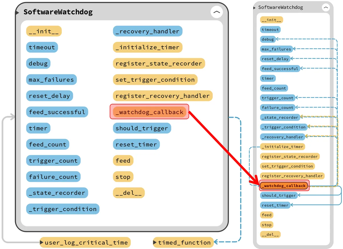
The process can be summarized as follows:
- Watchdog feeding detection: First, read the
feed_successfulflag to check whether a watchdog feeding operation has been performed. If no watchdog feeding signal is received within the current cycle (i. e.,feed_successfulisFalse), increment the consecutive failure count and total trigger count, and output debug information. - Status record: If the user has registered the status record function, this function will be called to record the current status when the watchdog is not fed.
- Recovery and Reset Decision:
- When the number of consecutive failures reaches the maximum allowed number of consecutive watchdog non-feeding attempts
max_failures, the recovery operation will be attempted first. - If the recovery operation succeeds, the consecutive failure count is reset; if the recovery fails, whether to initiate a system reset is determined by triggering condition judgment (if a condition function is registered).
- System reset is implemented by creating a one-shot timer, which invokes
reset_delayafter a delay of millisecondsreset ()to perform the reset.
- When the number of consecutive failures reaches the maximum allowed number of consecutive watchdog non-feeding attempts
The specific timing sequence is shown in the following figure:
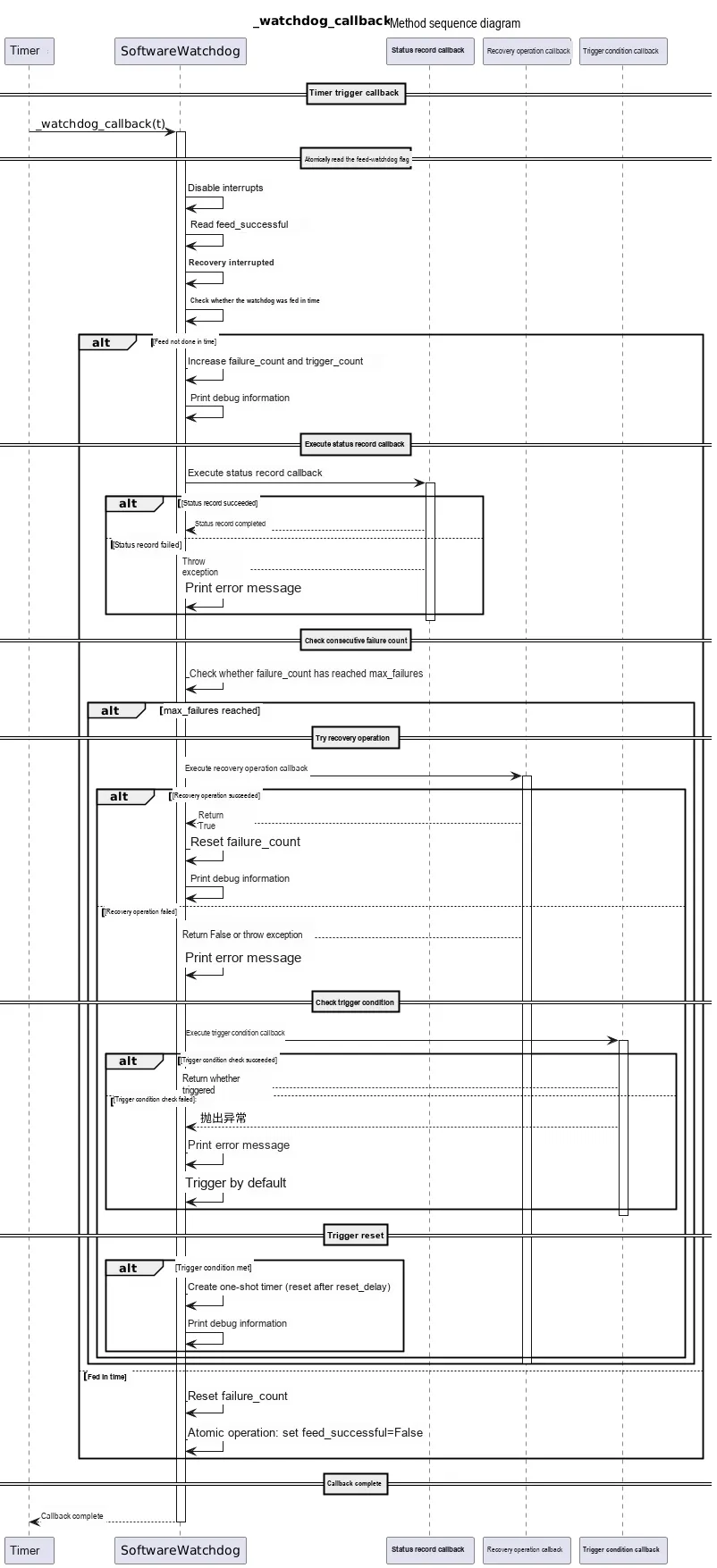
Users can implement custom callback function registration through the following three methods:
- Status Recording function: Users can register a status recording callback function via the
register_state_recordermethod, which can be used to record the current system status, log information, etc. , to facilitate troubleshooting. - Trigger condition judgment function: A callback function that returns a Boolean value is set via the
set_trigger_conditionmethod, which is used to determine whether the condition for triggering a system reset is met after a recovery failure. Users can customize it according to the specific requirements of the system. - Recovery Operation Function: Register a recovery operation callback function via the
register_recovery_handlermethod. This function will be invoked to attempt system recovery when consecutive watchdog feeding failures reach the upper limit. If the recovery succeeds, the failure count will be reset; otherwise, the system may enter a reset procedure depending on the trigger conditions.
Next, we define several custom callback functions to test this class:
# Python env   : MicroPython v1.23.0
# -*- coding: utf-8 -*-
# @Time    : 2024/8/16 AM 10:51
# @Author  : Li Qingshui
# @File    : main.py
# @Description : WDT watchdog timer class experiment, implemented with a Pico software timer

# ======================================== Import Modules ========================================

# Import hardware-related modules
from machine import Timer, reset, disable_irq, enable_irq
# Import time-related modules
import time
# Import the scheduler method
from micropython import schedule
# Import micropython-related modules
import micropython

# ======================================== Global Variables ============================================

# Set the threshold for the trigger condition
threshold = 10
# Assume the current value is 0
current_value = 12
# Declare the watchdog object
watchdog = None

# ======================================== Functions ============================================

# User-defined status recording function
def user_log_critical_time() -> None:
    """
    User-defined status recording function, used to write the current timestamp, current value, watchdog trigger count, and consecutive feed failure count to the log file.
    When the log file exceeds 50 lines, a new log file is created automatically.

    Args:
        None

    Returns:
        None

    Raises:
        Exception: If an error occurs while writing to the log file.
    """
    # Declare global variables
    global watchdog, current_value

    # Get the current timestamp
    timestamp = time.ticks_ms()

    # Base name of the log file
    log_base_name = "/log"
    log_extension = ".txt"
    log_index = 0
    log_file = f"{log_base_name}{log_index}{log_extension}"

    # Find the latest log file
    while True:
        try:
            # Try to open the file to check whether it exists
            with open(log_file, "r") as f:
                lines = f.readlines()
                # If the file has fewer than 10 lines, keep using the current file
                if len(lines) < 10:
                    break
        except OSError:
            # If the file does not exist, use the current file
            break
        # If the file has more than 10 lines, increment the index and try the next file
        log_index += 1
        log_file = f"{log_base_name}{log_index}{log_extension}"

    # Write the timestamp, current value, watchdog trigger count, and consecutive feed failure count to the log file
    try:
        with open(log_file, "a") as f:
            # Use % to format the string
            log_entry = "Timestamp: %d ms, Current Value: %d, Triggers: %d, Failures: %d\n" % (
                timestamp, current_value, watchdog.trigger_count, watchdog.failure_count
            )
            f.write(log_entry)
            # Ensure the data is written to the storage device
            f.flush()
    except Exception as e:
        print("[Error] Failed to write log:", str(e))

# User-defined trigger condition function
@micropython.native
def user_check_threshold() -> bool:
    """
    User-defined trigger condition function, used to determine whether the threshold has been reached.

    Args:
        None

    Returns:
        bool: True means the threshold has been reached, False means it has not been reached

    Raises:
        None
    """
    # Declare global variables
    global current_value, threshold

    # Check whether the threshold has been reached
    if current_value >= threshold:
        # Trigger threshold reached, return True and print information
        print("[Trigger] Threshold reached, triggering watchdog...")
        return True

    # Threshold not reached, return False and print information
    print("[Info] Current value is below threshold, no need to trigger watchdog...")
    return False

# Custom recovery action function
@micropython.native
def user_recovery_handler() -> bool:
    """
    User-defined recovery action function, used to perform the recovery action.

    Args:
        None

    Returns:
        bool: True means the recovery action succeeded, False means the recovery action failed

    Raises:
        Exception: If an error occurs while performing the recovery action.
    """
    # Declare global variables
    global watchdog

    # Print the recovery action information
    print("[Recovery] Attempting to recover system...")

    # Simulate the recovery action
    try:
        # The user can perform the recovery action here, for example restarting the system or reconnecting to the network.
        pass
    except Exception as e:
        print("[Error] Failed to recover system:", str(e))
        # Return False to indicate the recovery action failed
        return False

    # Print the recovery action success message
    print("[Recovery] Recovery operation completed successfully.")

    # Return True to indicate the recovery action succeeded
    return True
Next, we will explain its function:
- Status Record
user_log_critical_time ()function: We record the critical status information of the system, including the current timestamp, current value, watchdog trigger count, and consecutive watchdog feed failure count, and create a log file to write these critical pieces of information into the log file:- Log File Management: By constructing log file names (e. g.,
/log0.txt,/log1.txt, etc.), it sequentially checks whether the current log file exists and whether the number of lines in the file is below the threshold; if the line count of the current file reaches or exceeds the threshold, the log file index is incremented and a new file is used for logging, so as to prevent a single file from becoming excessively large. - Status Record: Obtain the current system time (in milliseconds), and construct the log entry content using the configured global variables; use the
%format string to concatenate the log entry, then write it to the file in append mode. - Exception Handling: Use
try/exceptto catch exceptions in file operations, ensure that a prompt can be output when an error is encountered while writing logs, and avoid program interruption.
- Log File Management: By constructing log file names (e. g.,
- Trigger Condition Judgment
user_check_threshold ()function: Check whether the current system status value reaches the preset threshold. Ifcurrent_valueis greater than or equal to the threshold, the trigger condition is considered satisfied, andTrueis returned with a prompt message output; otherwise,Falseis returned. This function is only used to test the trigger condition judgment function of the software timer class, and the current system status value is set to a fixed value for the convenience of explanation. - Recovery operation
user_recovery_handler ()function: Here, we simulate the execution of a system recovery operation. This function is called to attempt recovery when the system fails to feed the watchdog consecutively for a certain number of times; if the recovery operation succeeds (it is always simulated as successful in this example), it returnsTrue; if an exception occurs or the operation fails, it returnsFalse. For the convenience of explanation, we assume here that the recovery operation succeeds.
Here, in the trigger condition judgment user_check_threshold () function and the recovery operation user_recovery_handler () function, we use the function decorator @micropython.native to enable the native code emitter; the generated native code runs faster with a significant performance improvement (approximately twice that of bytecode), at the cost of a larger native code size that occupies more storage space.
Meanwhile, import a timing decorator additionally, which is used to calculate and print the running time of the function/method:
# Timing decorator, used to measure function run time
@micropython.native
def timed_function(f: callable, *args: tuple, **kwargs: dict) -> callable:
    """
    Timing decorator, used to measure and print function/method run time.

    Args:
        f (callable): The function/method to be passed in
        args (tuple): Any number of positional arguments passed to function/method f
        kwargs (dict): Any number of keyword arguments passed to function/method f

    Returns:
        callable: Returns the timed function
    """
    myname = str(f).split(' ')[1]

    def new_func(*args: tuple, **kwargs: dict) -> any:
        t: int = time.ticks_us()
        result = f(*args, **kwargs)
        delta: int = time.ticks_diff(time.ticks_us(), t)
        print('Function {} Time = {:6.3f}ms'.format(myname, delta / 1000))
        return result

    return new_func
After initializing the software watchdog instance, you can use the register_state_recorder () method, the set_trigger_condition () method, and the register_recovery_handler () method to register relevant functions. Its implementation principle is realized by passing in and storing function references. Take the following register_recovery_handler () method as an example:
def register_state_recorder(self, recorder: callable[[], None]) -> None:
    """
    Register the status recording callback function.

    Args:
        recorder (callable): Callback function with no parameters and no return value, used to record status

    Returns:
        None

    Raises:
        TypeError: If the parameter recorder is not of callable type.
    """
    # Check whether recorder is a callable object
    if not callable(recorder):
        raise TypeError("State recorder must be callable")

    # Set the status recording callback function
    self._state_recorder = recorder
Here, recorder is just a function reference that points to the function passed in by the user; afterwards, when self._state_recorder () is invoked, it will execute the code of the original function.
We can register the relevant function with the following statement:
# Initialize the software watchdog, set the timeout to 4 seconds, the maximum consecutive failures to 3, and the reset delay to 1 second
watchdog = SoftwareWatchdog(timeout=4000, debug=True, max_failures=3, reset_delay=1000)
# Register the status recording callback function
watchdog.register_state_recorder(user_log_critical_time)
# Set the trigger condition callback function
watchdog.set_trigger_condition(user_check_threshold)
# Register the recovery action callback function
watchdog.register_recovery_handler(user_recovery_handler)
The following code can be found in the material package we provide elegance-devkit v1\Demo\53 WDG_Timer folder.
In the following example, we will use the SoftwareWatchdog software timer class implemented above to monitor the running status of the system, and perform a recovery operation when an exception occurs in the system. The complete code is shown below:
# Python env   : MicroPython v1.23.0
# -*- coding: utf-8 -*-
# @Time    : 2024/8/16 AM 10:51
# @Author  : Li Qingshui
# @File    : main.py
# @Description : WDT watchdog timer class experiment, implemented with a Pico software timer

# ======================================== Import Modules ========================================

# Import hardware-related modules
from machine import Timer, reset, disable_irq, enable_irq
# Import time-related modules
import time
# Import the scheduler method
from micropython import schedule
# Import micropython-related modules
import micropython

# ======================================== Global Variables ============================================

# Set the threshold for the trigger condition
threshold = 10
# Assume the current value is 0
current_value = 12
# Declare the watchdog object
watchdog = None

# ======================================== Functions ============================================

# User-defined status recording function
def user_log_critical_time() -> None:
    """
    User-defined status recording function, used to write the current timestamp, current value, watchdog trigger count, and consecutive feed failure count to the log file.
    When the log file exceeds 50 lines, a new log file is created automatically.

    Args:
        None

    Returns:
        None

    Raises:
        Exception: If an error occurs while writing to the log file.
    """
    # Declare global variables
    global watchdog, current_value

    # Get the current timestamp
    timestamp = time.ticks_ms()

    # Base name of the log file
    log_base_name = "/log"
    log_extension = ".txt"
    log_index = 0
    log_file = f"{log_base_name}{log_index}{log_extension}"

    # Find the latest log file
    while True:
        try:
            # Try to open the file to check whether it exists
            with open(log_file, "r") as f:
                lines = f.readlines()
                # If the file has fewer than 10 lines, keep using the current file
                if len(lines) < 10:
                    break
        except OSError:
            # If the file does not exist, use the current file
            break
        # If the file has more than 10 lines, increment the index and try the next file
        log_index += 1
        log_file = f"{log_base_name}{log_index}{log_extension}"

    # Write the timestamp, current value, watchdog trigger count, and consecutive feed failure count to the log file
    try:
        with open(log_file, "a") as f:
            # Use % to format the string
            log_entry = "Timestamp: %d ms, Current Value: %d, Triggers: %d, Failures: %d\n" % (
                timestamp, current_value, watchdog.trigger_count, watchdog.failure_count
            )
            f.write(log_entry)
            # Ensure the data is written to the storage device
            f.flush()
    except Exception as e:
        print("[Error] Failed to write log:", str(e))

# User-defined trigger condition function
@micropython.native
def user_check_threshold() -> bool:
    """
    User-defined trigger condition function, used to determine whether the threshold has been reached.

    Args:
        None

    Returns:
        bool: True means the threshold has been reached, False means it has not been reached

    Raises:
        None
    """
    # Declare global variables
    global current_value, threshold

    # Check whether the threshold has been reached
    if current_value >= threshold:
        # Trigger threshold reached, return True and print information
        print("[Trigger] Threshold reached, triggering watchdog...")
        return True

    # Threshold not reached, return False and print information
    print("[Info] Current value is below threshold, no need to trigger watchdog...")
    return False

# Custom recovery action function
@micropython.native
def user_recovery_handler() -> bool:
    """
    User-defined recovery action function, used to perform the recovery action.

    Args:
        None

    Returns:
        bool: True means the recovery action succeeded, False means the recovery action failed

    Raises:
        Exception: If an error occurs while performing the recovery action.
    """
    # Declare global variables
    global watchdog

    # Print the recovery action information
    print("[Recovery] Attempting to recover system...")

    # Simulate the recovery action
    try:
        # The user can perform the recovery action here, for example restarting the system or reconnecting to the network.
        pass
    except Exception as e:
        print("[Error] Failed to recover system:", str(e))
        # Return False to indicate the recovery action failed
        return False

    # Print the recovery action success message
    print("[Recovery] Recovery operation completed successfully.")

    # Return True to indicate the recovery action succeeded
    return True

# Timing decorator, used to measure function run time
@micropython.native
def timed_function(f: callable, *args: tuple, **kwargs: dict) -> callable:
    """
    Timing decorator, used to measure and print function/method run time.

    Args:
        f (callable): The function/method to be passed in
        args (tuple): Any number of positional arguments passed to function/method f
        kwargs (dict): Any number of keyword arguments passed to function/method f

    Returns:
        callable: Returns the timed function
    """
    myname = str(f).split(' ')[1]

    def new_func(*args: tuple, **kwargs: dict) -> any:
        t: int = time.ticks_us()
        result = f(*args, **kwargs)
        delta: int = time.ticks_diff(time.ticks_us(), t)
        print('Function {} Time = {:6.3f}ms'.format(myname, delta / 1000))
        return result

    return new_func

# ======================================== Custom Classes ============================================

# Allocate the emergency exception buffer (must be placed before all interrupt code)
micropython.alloc_emergency_exception_buf(100)

# Software watchdog class
class SoftwareWatchdog:
    """
    Software watchdog class, implementing watchdog functionality using MicroPython's Timer.
    This class encapsulates timer-based watchdog logic, supporting timeout detection, feeding operations, state recording, trigger condition checking and recovery operations.
    By registering callback functions, users can customize the state recording, trigger condition and recovery operation logic.

    Attributes:
        timeout (int): Watchdog timeout, in milliseconds (default 4000 ms).
        debug (bool): Whether to enable debug mode (enabled by default).
        max_failures (int): Maximum number of consecutive feeding failures (default 1).
        reset_delay (int): Delay before triggering a reset, in milliseconds (default 3000 ms).
        feed_successful (bool): Feed flag, indicating whether the watchdog was fed successfully.
        timer (Timer): Software timer instance, used to periodically check the feeding status.
        feed_count (int): Counter of the number of feedings.
        trigger_count (int): Counter of the number of watchdog triggers.
        failure_count (int): Counter of consecutive feeding failures.
        _state_recorder (callable): User-defined state recording callback function.
        _trigger_condition (callable): User-defined trigger condition callback function.
        _recovery_handler (callable): User-defined recovery action callback function.

    Methods:
        __init__(self, timeout: int = 4000, debug: bool = True, max_failures: int = 1, reset_delay: int = 3000) -> None:
            Initialize the software watchdog instance.

        _initialize_timer(self) -> None:
            Initialize the timer and set the callback function.

        register_state_recorder(self, recorder: callable[[], None]) -> None:
            Register the status recording callback function.

        set_trigger_condition(self, condition: callable[[], bool]) -> None:
            Set the trigger condition callback function.

        register_recovery_handler(self, handler: callable[[], bool]) -> None:
            Register the recovery action callback function.

        _watchdog_callback(self, t: Timer) -> None:
            Timer callback function. Checks whether the watchdog was fed in time, and also records status and checks the condition to decide whether to trigger a reset.

        feed(self) -> None:
            Feed the watchdog and reset the feed flag.

        stop(self) -> None:
            Stop the watchdog timer.

        __del__(self) -> None:
            Destructor, ensures the timer resources are released.
    """
    def __init__(self, timeout: int = 4000, debug: bool = True, max_failures: int = 1, reset_delay: int = 3000) -> None:
        """
        Initialize the software watchdog.

        Args:
            timeout (int): Watchdog timeout, in milliseconds (default 4000 ms).
            debug (bool): Whether to enable debug mode (enabled by default).
            max_failures (int): Maximum number of consecutive feeding failures (default 1).
            reset_delay (int): Delay before triggering a reset, in milliseconds (default 3000 ms).

        Returns:
            None

        Raises:
            ValueError: If the parameters timeout, max_failures, or reset_delay are not positive integers, or debug is not a boolean.
        """
        # Check the entry parameters
        if not isinstance(reset_delay, int) or reset_delay <= 0:
            raise ValueError("reset_delay must be a positive integer")

        if not isinstance(timeout, int) or timeout <= 0:
            raise ValueError("timeout must be a positive integer")

        if not isinstance(max_failures, int) or max_failures <= 0:
            raise ValueError("max_failures must be a positive integer")

        if not isinstance(debug, bool):
            raise TypeError("debug must be a boolean value")

        # Set the timeout
        self.timeout = timeout
        # Set the debug mode
        self.debug = debug
        # Set the maximum number of failures
        self.max_failures = max_failures
        # Set the reset delay time
        self.reset_delay = reset_delay

        # Initialize the feed flag to False
        self.feed_successful = False
        # Initialize the software timer
        self.timer = Timer(-1)

        # Initialize the feed count
        self.feed_count = 0
        # Initialize the watchdog trigger count
        self.trigger_count = 0
        # Initialize the consecutive feed failure count
        self.failure_count = 0

        # Initialize the user-defined status recording function to None
        self._state_recorder = None
        # Initialize the user-defined trigger condition function to None
        self._trigger_condition = None
        # Initialize the recovery action callback function to None
        self._recovery_handler = None

        # Initialize the timer
        self._initialize_timer()

    def _initialize_timer(self) -> None:
        """
        Initialize the timer and set the callback function.

        Args:
            None

        Returns:
            None
        """
        # Initialize the timer, set the period and callback function
        self.timer.init(period=self.timeout, mode=Timer.PERIODIC, callback=lambda t: schedule(self._watchdog_callback, t))

    def register_state_recorder(self, recorder: callable[[], None]) -> None:
        """
        Register the status recording callback function.

        Args:
            recorder (callable): Callback function with no parameters and no return value, used to record status

        Returns:
            None

        Raises:
            TypeError: If the parameter recorder is not of callable type.
        """
        # Check whether recorder is a callable object
        if not callable(recorder):
            raise TypeError("State recorder must be callable")

        # Set the status recording callback function
        self._state_recorder = recorder

    def set_trigger_condition(self, condition: callable[[], bool]) -> None:
        """
        Set the trigger condition callback function.

        Args:
            condition (callable): Callback function with no parameters that returns bool; returning True means a restart is allowed to trigger.

        Returns:
            None

        Raises:
            TypeError: If the parameter condition is not of callable type.
        """
        # Check whether condition is a callable object
        if not callable(condition):
            raise TypeError("Trigger condition must be callable")

        # Set the trigger condition callback function
        self._trigger_condition = condition

    def register_recovery_handler(self, handler: callable[[], bool]) -> None:
        """
        Register the recovery action callback function.

        Args:
            handler (callable): Callback function with no parameters that returns a value, used to perform the recovery action; a return value of True means the recovery action succeeded, False means it failed.

        Returns:
            None

        Raises:
            TypeError: If the parameter handler is not of callable type.
        """
        # Check whether handler is a callable object
        if not callable(handler):
            raise TypeError("Recovery handler must be callable")

        # Set the recovery action callback function
        self._recovery_handler = handler

    # Use the @timed_function decorator to measure the run time of the SoftwareWatchdog._watchdog_callback method
    @timed_function
    def _watchdog_callback(self, t: Timer) -> None:
        """
        Timer callback function. Checks whether the watchdog was fed in time, and also records status and checks the condition to decide whether to trigger a reset.

        Args:
            t (Timer): Timer object (passed in automatically by Timer).

        Returns:
            None

        Raises:
            Exception: If an error occurs while executing the status recording callback function.
            Exception: If an error occurs while executing the recovery action callback function.
            TypeError: If the return value of the recovery action callback function is not of boolean type.
            Exception: If an error occurs while executing the trigger condition callback function.
        """

        # Read the feed flag atomically
        irq_state = disable_irq()
        feed_flag = self.feed_successful
        enable_irq(irq_state)

        # Check whether the watchdog was fed in time
        if not feed_flag:
            # Increase the consecutive failure count
            self.failure_count += 1
            # Increase the trigger count
            self.trigger_count += 1

            # If debug mode is on, print the trigger information
            if self.debug:
                print("[Watchdog] Triggered ({} failures, {} total triggers)".format(
                    self.failure_count, self.trigger_count))

            # Execute status recording (if registered)
            if self._state_recorder:
                try:
                    self._state_recorder()
                except Exception as e:
                    if self.debug:
                        print("[Error] Failed to record state:", str(e))

            # Check whether the consecutive failure count has reached the maximum
            if self.failure_count >= self.max_failures:

                # Flag indicating whether the recovery action succeeded
                recovery_successful = False

                # Try the recovery action
                if self._recovery_handler:
                    try:
                        if self.debug:
                            print("[Watchdog] Attempting recovery...")
                        # Try the recovery action
                        recovery_successful = self._recovery_handler()
                        # Check whether recovery_successful is a bool variable
                        if not isinstance(recovery_successful, bool):
                            raise TypeError("Recovery handler must return a boolean value")
                    except Exception as e:
                        if self.debug:
                            print("[Error] Recovery handler failed:", str(e))

                # Check whether the recovery action succeeded
                if recovery_successful:
                    # Reset the consecutive failure count
                    self.failure_count = 0
                    # Reset the should-trigger flag
                    self.should_trigger = False
                    if self.debug:
                        print("[Watchdog] Recovery successful, resetting failure count...")
                else:
                    # If recovery failed, check the trigger condition

                    # Trigger by default
                    should_trigger = True
                    # Check whether the trigger condition is registered
                    if self._trigger_condition:
                        try:
                            # Execute the trigger condition check
                            should_trigger = self._trigger_condition()
                        except Exception as e:
                            if self.debug:
                                print("[Error] Trigger condition check failed:", str(e))
                            # Trigger by default
                            should_trigger = True

                    # If the trigger condition is met, trigger a reset
                    if should_trigger:
                        if self.debug:
                            print("[Watchdog] Max failures reached, resetting system after %d ms..." %(self.reset_delay))
                        # Create a one-shot timer that performs the reset after the specified delay
                        self.reset_timer = Timer(-1)
                        self.reset_timer.init(period=self.reset_delay, mode=Timer.ONE_SHOT, callback=lambda t: reset())
        else:
            # Reset the consecutive failure count
            self.failure_count = 0

            # Atomic reset
            irq_state = disable_irq()
            # Reset the feed flag
            self.feed_successful = False
            enable_irq(irq_state)

    def feed(self) -> None:
        """
        Feed the watchdog and reset the feed flag.

        Args:
            None

        Returns:
            None
        """
        irq_state = disable_irq()
        self.feed_successful = True
        # Increase the feed count
        self.feed_count += 1
        enable_irq(irq_state)

        # If debug mode is on, print the feed time
        if self.debug:
            print("Watchdog fed at:", time.ticks_ms())

    def stop(self) -> None:
        """
        Stop the watchdog timer.

        Args:
            None

        Returns:
            None
        """
        # Stop the timer
        self.timer.deinit()
        if self.debug:
            print("Watchdog stopped.")

    def __del__(self):
        """
        Destructor: ensures the timer resources are released.

        Args:
            None

        Returns:
            None
        """
        self.timer.deinit()
        if self.debug:
            print("Watchdog resources released.")

# ======================================== Initialization ==========================================

# Power-on delay of 3 s
time.sleep(3)
# Print debug information
print("FreakStudio : Implement Watchdog Timer using a software timer Test")

# Initialize the software watchdog, set the timeout to 4 seconds, the maximum consecutive failures to 3, and the reset delay to 1 second
watchdog = SoftwareWatchdog(timeout=4000, debug=True, max_failures=3, reset_delay=1000)
# Register the status recording callback function
watchdog.register_state_recorder(user_log_critical_time)
# Set the trigger condition callback function
watchdog.set_trigger_condition(user_check_threshold)
# Register the recovery action callback function
watchdog.register_recovery_handler(user_recovery_handler)

# ========================================  Main Program  ===========================================

# Feed the watchdog ten times within the timeout, so the watchdog timer does not trigger a reset
for i in range(2):
    # Feed the watchdog
    watchdog.feed()
    # Delay 2 seconds
    time.sleep(2)
Burn the program, connect the Raspberry Pi Pico, and the terminal output is as follows:
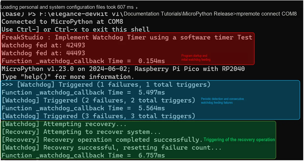
3.2.1 Application Experiment.mp4 6.2 MB
It can be seen that the basic flow of the program operation is as follows:
- Program Startup and Initial Watchdog Feeding: First, the program starts up, and the terminal first displays
"FreakStudio : Implement Watchdog Timer using a software timer Test", then prints the"Watchdog fed at: …"message twice, indicating thatwatchdog.feed ()has been called twice in the main program; these two calls successfully set the watchdog feeding flag to True and recorded the feeding time at the same time;Meanwhile, when the watchdog callback function is called for the first time (outputting"Function _watchdog_callback Time = … ms"), it indicates that the timer has been started and entered the periodic detection phase.
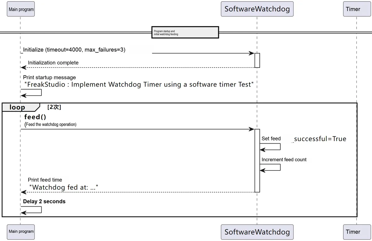
- Periodic detection and consecutive watchdog feeding failures: As the main program loop terminates (and no further calls to
feed ()are made), the watchdog callback function detects that feed_successful is False in each subsequent cycle, thus entering the "watchdog not fed in time" state. During each cycle where the watchdog is not fed, the program operates according to the following steps:- Increment the consecutive failure count (
failure_count) and the total trigger count (trigger_count); - When the dog is not fed for the first time, the output
"[Watchdog] Triggered (1 failures, 1 total triggers)"; - During the second test,
"[Watchdog] Triggered (2 failures, 2 total triggers)"; - When consecutive failures reach 3 times (for example, the first time it reaches
"(3 failures, 3 total triggers)"), the system enters the recovery phase.
- Increment the consecutive failure count (
- Trigger of recovery operation: When the number of consecutive watchdog feeding failures reaches the preset maximum value (3 times in this example), output
"[Watchdog] Attempting recovery. .."to start the recovery operation: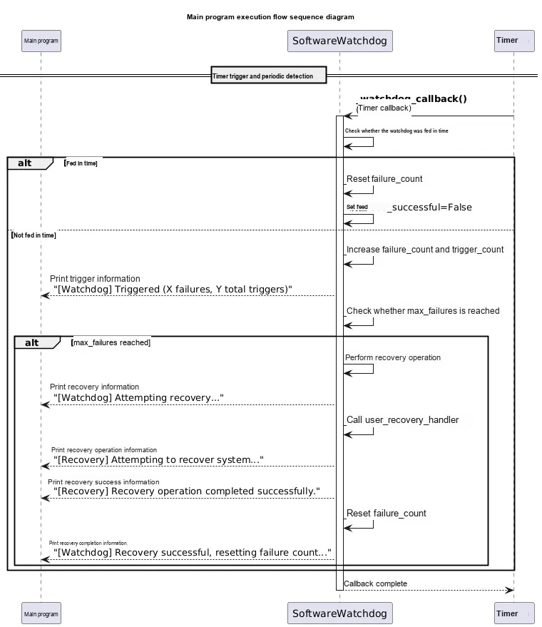
- Call the user-defined recovery operation function
user_recovery_handler, and output in sequence:“[Recovery] Attempting to recover system...”;“[Recovery] Recovery operation completed successfully.”;-
“[Watchdog] Recovery successful, resetting failure count...”.
Indicates that the recovery operation succeeded and the consecutive failure count has been reset to 0.
- After recovery succeeds, the watchdog resumes operation. Although the consecutive failure count is reset to zero at this point, the total trigger count continues to accumulate (for example, if the total number of triggers after the first cycle is 3, the first trigger of the next cycle will display "(1 failures, 4 total triggers)"; this pattern repeats continuously in subsequent cycles, and a recovery operation is performed once every 3 consecutive times that the watchdog is not fed.
- Call the user-defined recovery operation function
We can use the mpremote tool to view the log file with the following command:
mpremote cat log0.txtIt can be seen that the log file records in detail the current timestamp, the current system status value, the number of watchdog triggers, and the number of consecutive watchdog feeding failures:
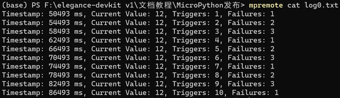
We can also use the mpremote cp : log0.txt./log0.txt command to copy this log file to the specified path:
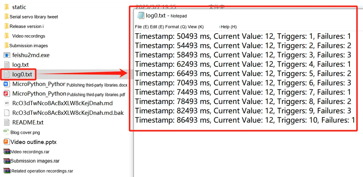
3.2.2 Application Experiment.mp4 4.6 MB
Next, we try to skip the recovery operation by commenting out the statement that registers the recovery operation callback function, and run it again:
# Register the recovery action callback function
# watchdog.register_recovery_handler(user_recovery_handler)
It can be seen that the device resets after 3 consecutive watchdog feeding failures.
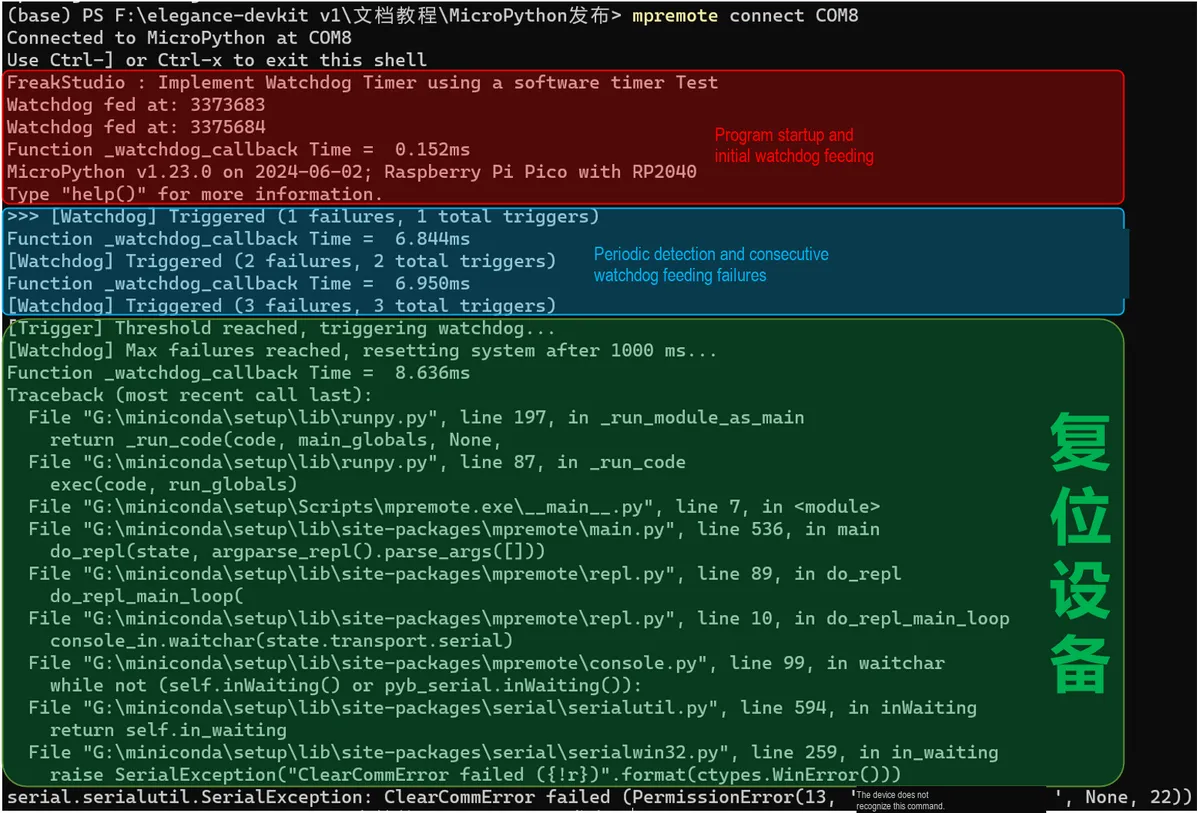
3.2.3 Application Experiment.mp4 2.6 MB
In practice, software watchdogs also have certain limitations. Since their operation relies on the system's own hardware and software resources, software watchdogs may fail when a serious system error occurs. For example, if there is a problem with the interrupt service routine (ISR) in the system, causing the entire system to become paralyzed, the software watchdog may fail to perform the reset operation in a timely manner, as it itself runs on the system's resources. In such cases, the system may be unable to recover on its own, leading to more severe consequences.
3.3 Multi-threaded Implementation of Watchdog Experiment
Similarly, a software timer-like mechanism can also be applied here
The core idea of the multi-threaded software watchdog is to use an independent watchdog thread to monitor the status of other worker threads, and each worker thread periodically "feeds the dog" to indicate that it is still operating normally: the watchdog thread is responsible for monitoring the global count variable and increments the variable at fixed intervals; after completing a certain operation, the worker thread clears the global count variable, which is the "dog feeding" operation. If the watchdog thread finds that the global count variable exceeds a predefined upper limit (for example, 2), it determines that the main program thread has stalled and takes measures to restart the device.
Here, there are two points to note:
- First of all, the MicroPython running on
RP2040can only run two threads at the same time, because the RP2040 has two cores, and each core can only run one thread: If you try to run more than two threads, it will lead to resource conflicts or other errors. This limitation requires special attention when designing multi-threaded applications, especially when using the RP2040 for complex tasks. If you need to manage multiple tasks, you can simulate multi-threaded behavior through appropriate task scheduling and coordination mechanisms, such as polling or timers, without actually creating multiple threads. - All reset-related operations (e. g.
machine.reset ()ormachine.soft_reset ()) can only be performed in the main thread; otherwise, errors such asOSErrorexceptions will be triggered. The main reason is that critical system operations (such as reset) involve low-level hardware and system state management, which must be completed in the main thread to ensure state consistency and proper resource management. If a reset operation is called in another thread, it may lead to state confusion or resource contention, thereby causing errors;Meanwhile, USB-related operations are usually handled by the TinyUSB driver, and the reset operation will trigger the execution of the underlying USB callback function. If the reset operation is performed in a non-main thread, it may trigger a recursion call of the TinyUSB callback, which is not allowed for these callback functions.
Common errors that occur when performing a reset operation in a non-main thread are as follows:
>>> FATAL: uncaught exception 20008830
OSError
Or:
>>> [Watchdog] Main thread is unresponsive. System should restart!
FATAL: uncaught exception 20008830
OSError:
Or:
>>> Watchdog: Main thread is unresponsive. System should restart!
FATAL: uncaught exception 20008870
OSError: TinyUSB callback can't recurse
In the following code, we implement a multi-threaded software watchdog timer to monitor the running status of the main thread and the dog-feeding thread. When the dog-feeding thread fails to "feed the watchdog" periodically (i. e., fails to reset the counter regularly), the watchdog will determine that a system fault has occurred and attempt to restart the device.
The following code can be found in the material package we provide, in the elegance-devkit v1\Demo\54 WDG_Thread folder.
The sample code is as follows:
# Python env   : MicroPython v1.23.0
# -*- coding: utf-8 -*-
# @Time    : 2024/8/16 AM 11:14
# @Author  : Li Qingshui
# @File    : main.py
# @Description : WDT watchdog timer class experiment, implemented with Pico software multithreading

# ======================================== Import Modules ========================================

# Import the multithreading module
import _thread
# Import time-related modules
import time
# Import the hardware module
import machine
# Import the const constant
from micropython import const
import micropython

# ======================================== Global Variables ============================================

# Global variable, used for watchdog thread monitoring
watchdog_counter = 0

# If the watchdog is not fed within this count, the system restarts
WATCHDOG_MAX_COUNTER = const(2)
# Watchdog check interval (unit: seconds)
WATCHDOG_CHECK_INTERVAL = const(4)
# Feed thread execution interval (seconds)
FEED_INTERVAL = const(1)
# Maximum feed count, feeding stops once reached
FEED_COUNT = const(10)

# ======================================== Functions ============================================

# Allocate the emergency exception buffer (must be placed before all interrupt code)
micropython.alloc_emergency_exception_buf(100)

# Feeding-the-dog (watchdog feeding) thread
def feed_thread() -> None:
    """
    Watchdog feeding thread, used to periodically feed the watchdog and clear the watchdog counter to prevent the main thread from triggering a reset.

    Args:
        None

    Returns:
        None

    Raises:
        Exception: If an exception occurs during feeding, print the error message; it does not affect the main thread.
    """
    # Declare global variables
    global watchdog_counter

    # Watchdog feed counter
    feed_times = 0

    while True:
        try:
            # Feed the watchdog once every FEED_INTERVAL seconds
            time.sleep(FEED_INTERVAL)

            # Acquire the mutex
            lock.acquire()

            # If the feed count has not reached FEED_COUNT, perform the feed operation
            if feed_times < FEED_COUNT:
                # Feed the watchdog: clear watchdog_counter
                watchdog_counter = 0
                feed_times += 1
                print(f"[Feed] Feed the dog! ({feed_times}/{FEED_COUNT})")
            else:
                # Feed count reached FEED_COUNT, stop feeding
                print("[Feed] Stop feeding the dog!")
                # Exit the loop
                break

        except Exception as e:
            # Catch and print the exception
            print(f"[Feed] Error in feed thread: {e}")
        finally:
            # Release the mutex
            if lock.locked():
                lock.release()

# ======================================== Custom Classes ============================================

# ======================================== Initialization ==========================================

# Power-on delay of 3 s
time.sleep(3)
# Print debug information
print("FreakStudio : Implement Watchdog Timer using a multi-threading Test")
# Create an LED object
led = machine.Pin(25, machine.Pin.OUT)

# ========================================  Main Program  ===========================================

# Acquire the mutex to protect shared resources when multiple threads access them
lock = _thread.allocate_lock()
# Start the watchdog feeding thread
_thread.start_new_thread(feed_thread, ())

# Main thread: monitor whether `watchdog_counter` has timed out
try:
    # Check whether watchdog_counter has timed out once every WATCHDOG_CHECK_INTERVAL seconds
    while True:
        try:
            # Acquire the mutex
            lock.acquire()

            # Toggle the LED to indicate the program is running
            led.toggle()
            # Simulate the main thread performing other tasks
            time.sleep(WATCHDOG_CHECK_INTERVAL-1)
            print("[Main] Main thread is running, checking watchdog...")

            # Check whether watchdog_counter is greater than WATCHDOG_MAX_COUNTER
            if watchdog_counter > WATCHDOG_MAX_COUNTER:
                # The feeding thread cannot perform the feed operation due to a fault
                print("[Watchdog] Feed thread is unresponsive. System should restart!")
                # Delay 1 second to ensure the debug information is output
                time.sleep(1)

                # Release the mutex
                if lock.locked():
                    lock.release()

                # Try to restart the system
                try:
                    # Soft reset the system: delete all Python objects and reset the Python heap
                    machine.soft_reset()
                except Exception as e:
                    # Catch and print the exception
                    print(f"[Error] Failed to restart system: {e}")

            # Increment the value of watchdog_counter
            watchdog_counter += 1

        except Exception as e:
            # Catch and print the exception
            print(f"[Main] Error in main thread: {e}")
        finally:
            # Release the mutex
            if lock.locked():
                lock.release()

except KeyboardInterrupt:
    # Catch user interrupt (such as Ctrl+C)
    print("[Main] Program interrupted by user.")
finally:
    # Make sure resources are released when the program ends
    print("[Main] Program ended.")
In the sample code above, we have completed the following tasks:
- Watchdog mechanism: A global variable
watchdog_counteris set as the watchdog counter. The main thread incrementswatchdog_counterperiodically, while the watchdog feeding thread resets it to zero periodically (i. e., "feeding the watchdog"). Ifwatchdog_counterexceeds the preset thresholdWATCHDOG_MAX_COUNTER, the watchdog feeding thread is considered to be faulty, and the system needs to be restarted. - Multithreaded design: The main thread is responsible for monitoring
watchdog_counterand executing core tasks (such as toggling the LED), while the watchdog feeding thread handles periodic "watchdog feeding", i. e., resettingwatchdog_counterto zero. The watchdog feeding thread performs a feed operation everyFEED_INTERVAL (1)second, and stops feeding after runningFEED_COUNT (10)times to simulate a program exception. - Mutex Lock Protection and System Reboot: Use
_thread.allocate_lock ()to create a mutex locklock, which is used to protect access to the global variablewatchdog_counterand prevent data inconsistency caused by multi-thread competition; meanwhile, if the watchdog detects that the petting thread has failed, the main thread will attempt to callmachine.soft_reset ()to reboot the system.
The program Sequence Diagram is shown below:
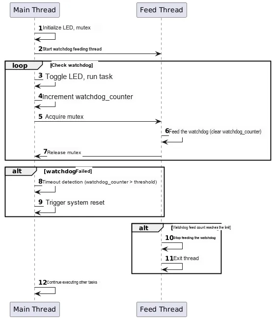
Here, we use machine.soft_reset () to restart the system:

Unlike machine.reset (), a hard reboot reinitializes the entire system;machine.soft_reset () only restarts the MicroPython interpreter without reinitializing the hardware. It clears the runtime state of MicroPython (such as variables, objects, stack, etc.), re-executes the startup scripts (such as boot.py and main.py), and does not disconnect the REPL connection in the meantime.
After flashing the code and connecting to the Raspberry Pi Pico remotely, the terminal output is as follows:
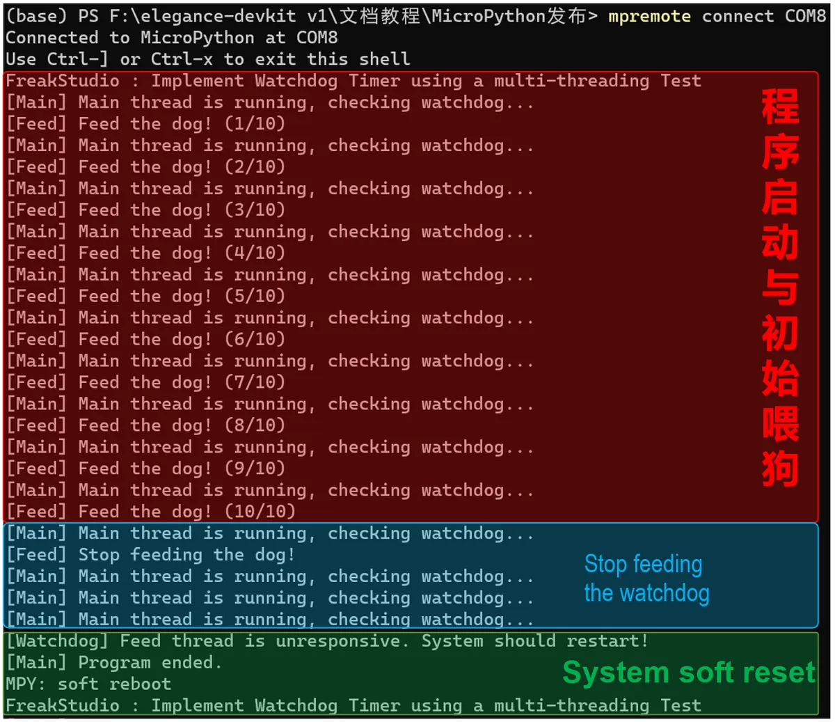
3.3 Application Experiment.mp4 1.8 MB
It can be seen that after stopping feeding the dog, the watchdog main thread restarts the device when the timeout period is reached. In a multi-tasking environment, we can use the watchdog multi-thread to quickly respond to problems occurring in the main thread.
3.4 External Watchdog Experiment
3.4.1 Design of DS1232 Chip Driver Code
DS1232 is an external watchdog chip used for hardware reset protection of the MCU. The driver objectives are as follows:
- Output WDI (Watchdog Input) pulses through the GPIO of the MCU.
- Toggle the WDI periodically to prevent the DS1232 from resetting the MCU due to timeout.
- Provides automatic dog feeding (Timer) and manual dog feeding (kick) two methods.
- Supports stopping dog feeding (stop) to trigger a reset test or a safe reset scenario.
- Provide easy-to-use, stable and reliable, ISR-safe interfaces.
The driver code files are listed as follows:
# Python env   : MicroPython v1.23.0
# -*- coding: utf-8 -*-
# @Time    : 2025/8/25 6:46 PM
# @Author  : Li Qingshui
# @File    : ds1232.py
# @Description : External DS1232 watchdog module driver

# ======================================== Import Modules =========================================

# Import hardware-related modules
from machine import Pin, Timer

# ======================================== Global Variables ============================================

# ======================================== Functions ============================================

# ======================================== Custom Classes ============================================

class DS1232:
    """
    This class controls the external DS1232 watchdog module, feeding the watchdog by periodically toggling the WDI pin to prevent the MCU from being reset.

    Attributes:
        wdi (Pin): machine.Pin instance used to output the feed pulse.
        state (int): Current WDI pin output state, 0 or 1.
        timer (Timer): machine.Timer instance used for periodic feeding.

    Methods:
        __init__(wdi_pin: int, feed_interval: int = 1000) -> None: Initialize the watchdog and start timed feeding.
        stop() -> None: Stop automatic feeding and set the WDI pin low.
        kick() -> None: Feed manually, toggling the WDI pin once immediately.

    Notes:
        - A Timer object is created during initialization to toggle WDI periodically.
        - _feed is an internal callback method and should not be called directly.
        - Most methods of this class are not ISR-safe; the Timer callback _feed is ISR-safe.
        - After stop(), the WDI pin stays low, and the DS1232 will reset the MCU after the timeout.

    ==========================================

    DS1232_Watchdog driver for controlling an external DS1232 watchdog module.
    Periodically toggles WDI pin to prevent MCU reset.

    Attributes:
        wdi (Pin): machine.Pin instance for feeding pulses.
        state (int): Current WDI output state, 0 or 1.
        timer (Timer): machine.Timer instance for periodic feeding.

    Methods:
        __init__(wdi_pin: int, feed_interval: int = 1000) -> None: Initialize the watchdog and start automatic feeding.
        stop() -> None: Stop automatic feeding and set WDI low.
        kick() -> None: Manually feed the watchdog by toggling WDI once.

    Notes:
        - Initializes a Timer to periodically toggle WDI.
        - _feed is an internal callback method, not recommended for direct user call.
        - Most methods are not ISR-safe; _feed callback is ISR-safe.
        - After stop(), WDI remains low; DS1232 will reset MCU on timeout.
    """

    def __init__(self, wdi_pin: int, feed_interval: int = 1000) -> None:
        """
        Initialize the DS1232 watchdog.

        Args:
            wdi_pin (int): WDI pin number.
            feed_interval (int): Feed interval in ms. Default is 1000ms.

        Returns:
            None

        Raises:
            ValueError: When wdi_pin is not an integer or feed_interval > 1000.
            RuntimeError: When Timer initialization fails.

        Notes:
            Timed feeding starts immediately after the object is created.
            The call involves timer resources and is not ISR-safe.

        ==========================================

        Initialize DS1232 watchdog.

        Args:
            wdi_pin (int): WDI pin number.
            feed_interval (int): Feeding interval in ms. Default is 1000ms.

        Returns:
            None

        Raises:
            ValueError: If wdi_pin is not an integer or feed_interval > 1000 ms.
            RuntimeError: If Timer initialization fails.

        Notes:
            Feeding starts immediately after object creation.
            Uses Timer resource, not ISR-safe.
        """
        # Parameter check
        if not isinstance(wdi_pin, int):
            raise ValueError("wdi pin must be an integer")
        if feed_interval > 1000:
            raise ValueError("feed_interval must be less than 1000ms")

        self.wdi = Pin(wdi_pin, Pin.OUT)
        # Current output state
        self.state = 0
        self.timer = Timer(-1)

        # Start the timer to feed periodically
        self.timer.init(period=feed_interval, mode=Timer.PERIODIC, callback=self._feed)

    def _feed(self, t: Timer) -> None:
        """
        Timer callback function: periodically toggles the WDI pin.

        Args:
            t (Timer): The timer object that triggered this callback.

        Returns:
            None

        Raises:
            None

        Notes:
            Internal method; users should not call it directly.
            Runs in interrupt context; ISR-safe.

        ==========================================

        Timer callback: toggle WDI pin periodically.

        Args:
            t (Timer): Timer instance triggering this callback.

        Returns:
            None

        Raises:
            None

        Notes:
            Internal method, not recommended for direct user call.
            Runs in interrupt context, ISR-safe.
        """
        # Toggle 0/1
        self.state ^= 1
        self.wdi.value(self.state)

    def stop(self) -> None:
        """
        Stop automatic feeding.

        Args:
            None

        Returns:
            None

        Raises:
            RuntimeError: When releasing the timer fails.

        Notes:
            After stopping, the WDI pin stays low, and the DS1232 will reset the MCU after the timeout.

        ==========================================

        Stop automatic feeding.

        Args:
            None

        Returns:
            None

        Raises:
            RuntimeError: If timer deinitialization fails.

        Notes:
            WDI pin is held low after stopping, DS1232 will reset MCU on timeout.
        """
        self.timer.deinit()
        self.wdi.value(0)

    def kick(self) -> None:
        """
        Manual feed: toggle the WDI pin once immediately.

        Args:
            None

        Returns:
            None

        Raises:
            RuntimeError: When the pin write fails.

        Notes:
            Usually used for a temporary feed, or to maintain feeding manually after automatic feeding is stopped.

        ==========================================

        Manually feed watchdog by toggling WDI once.

        Args:
            None

        Returns:
            None

        Raises:
            RuntimeError: If pin write fails.

        Notes:
            Useful for temporary feeding or manual feeding after stopping auto mode.
        """
        self.state ^= 1
        self.wdi.value(self.state)

# ======================================== Initialization ==========================================

# ========================================  Main Program  ===========================================
In terms of initialization, we pass the WDI pin number and the watchdog feeding interval, and the DS1232 class will automatically create a GPIO pin object and start a timer to implement periodic watchdog feeding, ensuring that the MCU will not be reset during normal operation.
The DS1232 class has the following methods:_feed is an internal Timer callback used to automatically toggle WDI, kick can be used to manually feed the watchdog, stop can stop automatic watchdog feeding and make the DS1232 reset the MCU after timeout.
When in use, we only need to create a DS1232 object, and then:
- Timer starts, and
feed_intervalms after each interval,_feedis called. _feedToggle WDI → The DS1232 watchdog timer is reset.- Normal operation of the MCU → Manual watchdog feeding can be performed via
kick. - Test or reset required → Call
stop ()→ WDI pulled low → DS1232 timeout → MCU reset.
3.4.2 Application Experiment
In the code below, we initialize the DS1232 watchdog timer, perform periodic watchdog feeding, detect reset signals, and observe the process of the MCU being reset when a simulated timeout occurs or watchdog feeding is manually stopped.
Here, we first insert the Fengya No.1 board-Grove interface expansion board into the Fengya No.1 board-universal compatible expansion board , and then use the HY2.0-4P cable to connect the GraftSense-DS1232 watchdog module to the Fengya No.1 board-Grove interface expansion board 's UART1 interface, as shown in the figure below:
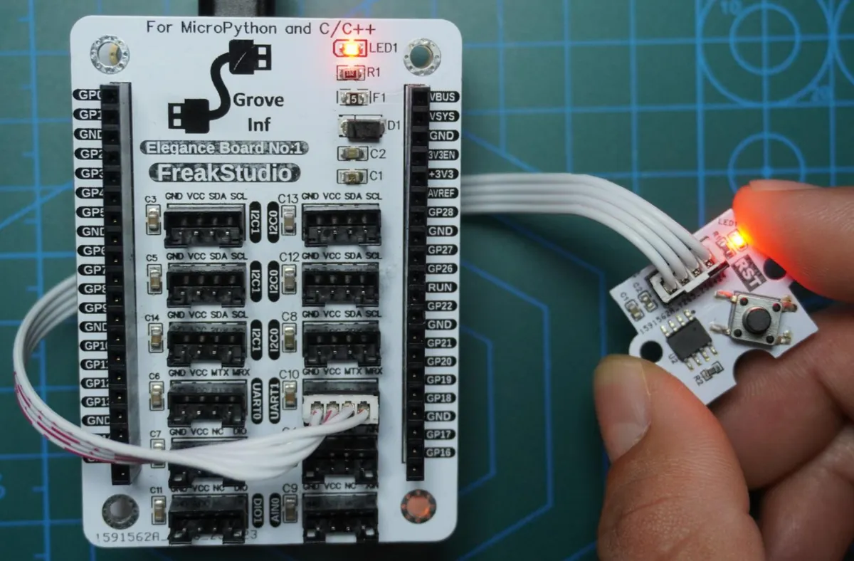
The wiring conditions are shown in the following table:
| DS1232 module pin | MCU GPIO / Power | Function description |
|---|---|---|
| VCC | 5V | Module power positive, a stable 5V supply is recommended |
| GND | GND | Module power negative, common ground with the MCU |
| WDI | GPIO4 | Watchdog Input; the MCU toggles this pin periodically to feed the watchdog |
| RST | GPIO5 | Watchdog Reset Output; the MCU can detect the reset signal through an interrupt |
Here, the GraftSense-DS1232 watchdog module has the short-circuit points on its back side for TD and TOL both soldered to VCC.
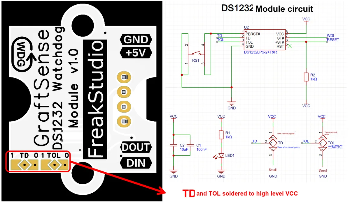
The following code can be found in the material package we provide elegance-devkit v1\Demo\75 WDG_EXT folder.
Examples are shown as follows:
# Python env   : MicroPython v1.23.0
# -*- coding: utf-8 -*-
# @Time    : 2025/8/25 6:46 PM
# @Author  : Li Qingshui
# @File    : main.py
# @Description : External DS1232 watchdog module test program

# ======================================== Import Modules =========================================

# Import hardware-related modules
from machine import Pin, Timer
# Import time-related modules
import time

# Import the DS1232 watchdog module
from ds1232 import DS1232

# ======================================== Global Variables ============================================

# GPIO connected to the DS1232 WDI pin
WDI_PIN = 4
# GPIO connected to the DS1232 RST pin
RST_PIN = 5
# Feed interval, in ms
FEED_INTERVAL = 300
# Delay before stopping feeding, in ms
STOP_FEED_DELAY = 10000

# Define global variables
wdg = None
stop_feed_timer = None
# Global flag: detects whether RST was triggered
system_reset_flag = False

# ======================================== Functions ============================================

def rst_callback(pin: Pin) -> None:
    """
    DS1232 RST pin trigger callback function.

    Args:
        pin (Pin): The GPIO pin that triggered this callback.

    Returns:
        None
    """
    # Declare global variables
    global system_reset_flag

    # Set the flag; the main loop breaks out after detecting it
    system_reset_flag = True
    print("DS1232 RST pin triggered.")

def stop_feed_callback(t: Timer) -> None:
    """
    Timer callback: stop automatic feeding, simulating a feed failure to trigger a reset.

    Args:
        t (Timer): Timer object

    Returns:
        None
    """
    # Declare global variables
    global wdg, stop_feed_timer

    print("Stop feeding watchdog.")
    # Stop feeding
    wdg.stop()
    # Stop this timer so it runs only once
    stop_feed_timer.deinit()

# ======================================== Custom Classes ============================================

# ======================================== Initialization ==========================================

# Power-on delay of 3 s
time.sleep(3)
# Print debug information
print("FreakStudio:: DS1232 Watchdog Test Program.")

# Initialize the DS1232 watchdog
wdg = DS1232(wdi_pin=WDI_PIN, feed_interval=FEED_INTERVAL)
# Feed manually immediately
wdg.kick()

# Configure the RST pin as input with pull-up, triggering the callback
rst_pin = Pin(RST_PIN, Pin.IN, Pin.PULL_UP)
rst_pin.irq(trigger=Pin.IRQ_FALLING, handler=rst_callback)

# Define a timer to delay stopping feeding
stop_feed_timer = Timer()
stop_feed_timer.init(period=STOP_FEED_DELAY, mode=Timer.ONE_SHOT, callback=stop_feed_callback)

# ========================================  Main Program  ===========================================

# Start feeding
print("Start feeding watchdog.")

try:
    # Infinite loop
    while True:
        # Print a log with timestamp
        current_time = time.ticks_ms()
        print(f"System running... Time: {current_time} ms")

        # Check the RST trigger flag
        if system_reset_flag:
            print("System starting reset...")
            # Break out of the while loop
            break

        time.sleep(1)
except KeyboardInterrupt:
    print("Program interrupted.")
finally:
    # Stop feeding
    wdg.stop()
    # Stop the timer
    stop_feed_timer.deinit()
Here, first of all, after the MCU is powered on, we delay for 3 seconds to complete stable startup, then print debug information, and create a DS1232 object to initialize the WDI pin and Timer, so as to implement automatic periodic dog feeding; meanwhile, we immediately call kick () to manually toggle the WDI once to ensure that the watchdog starts counting; next, configure the RST pin as input pull-up and bind an interrupt callback to detect the DS1232 timeout reset signal; then start a one-shot timer to delay stopping the automatic dog feeding, so as to simulate a reset triggered by failed dog feeding. The program then enters the main loop:
- Print the system running time (in milliseconds) every second.
- Check the
system_reset_flagflag; if theRSTpin is triggered, print the reset information and exit the loop. - Catch
KeyboardInterruptto allow users to manually interrupt the program.
After the loop ends, stop the automatic watchdog feeding of DS1232 in the finally block and release the timer resources to ensure the status safety of the MCU and Timer, thus completing the entire watchdog test process.
Burn the code, open the terminal, and the running result is shown as follows:
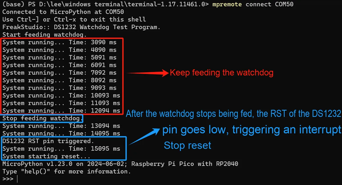
3.4.2 Application Experiment (1).mp4 1.4 MB
It can be seen that the program runs normally, and the overall process is as follows:
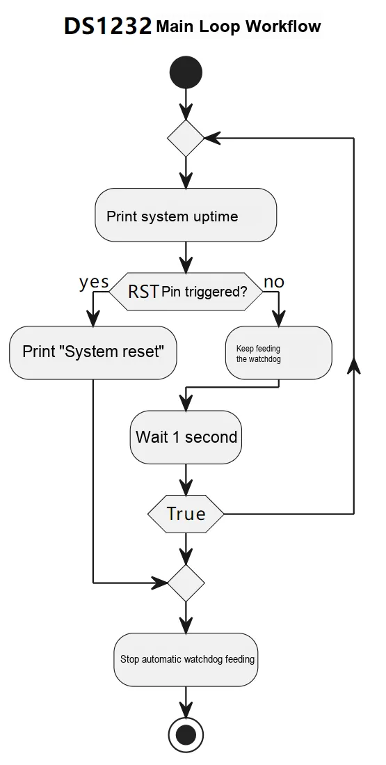
After a reboot, before we stop watchdog feeding, while the MCU is normally sending pulses to the watchdog, press the RST button on the watchdog module, and you will find that a normal reset can still be triggered. This design is intended to provide a reliable external hard reset mechanism: when the software runs away, or you need to manually restart the entire board, manual reset should have the highest priority.
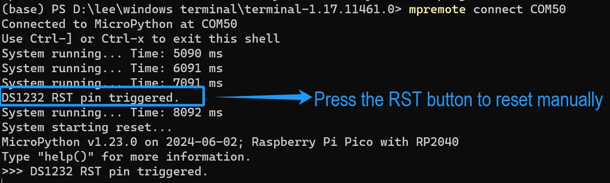
References
- Detailed Explanation of the Working Principle of Watchdog
https://www.cnblogs.com/Alfred-HOO/articles/15957581.html
- Watchdog Chip - SP706 - Debugging Log
https://blog.csdn.net/weixin_40407893/article/details/117956750
- A Guide to Understanding Watchdog Timers
https://blog.csdn.net/fg247778718/article/details/138580080
- Watchdog Timer
https://blog.csdn.net/weixin_44216065/article/details/90646531
- Introduction to Watchdog Timers
https://www.embedded.com/introduction-to-watchdog-timers/
- TPS3851 External Watchdog Chip: What Is a Watchdog Timer and Why Is It Important?
https://www.ti.com/document-viewer/ja-jp/lit/html/SSZTAH7
- What is a watchdog timer (WDT)?
https://www.ablic.com/en/semicon/products/automotive/automotive-watchdog-timer/intro/
- What is a Watchdog? A Detailed Explanation of the Working Principle and Applications of Watchdog Technology
https://www.ebyte.com/new-view-info.aspx?id=2551
- STM32 Peripherals: Dedicated Timers IWDG, WWDG, RTC
https://www.cnblogs.com/rayoli/p/14825231.html
- RP2040 (Raspberry Pi Pico) Watchdog
https://www.taterli.com/7559
- RP2040 Boot Sequence
https://vanhunteradams.com/Pico/Bootloader/Boot_sequence.html
- [Tutorial] Fix for RP2040 Firmware Issues: FLASH Needs to Be Cleared
https://mc.dfrobot.com.cn/thread-313092-1-1.html
- Bricked MicroPython rescue firmware
https://forums.raspberrypi.com/viewtopic.php?f=146&t=305432
- Delete flashed .uf2 file on Pico
https://forums.raspberrypi.com/viewtopic.php?t=365927
- Multithreaded Programming in the MicroPython Environment on RP2040
https://www.xpstem.com/article/10586#
- Watchdog Chip - SP706 - Debugging Log
https://blog.csdn.net/weixin_40407893/article/details/117956750
Appendix
What should I do if the main.py file in MicroPython keeps running and restarting repeatedly?
When the main.py file on the Raspberry Pi Pico causes abnormal or "out-of-control" device behavior, making the device fail to boot properly or enter REPL mode — for example, when the watchdog timer is set too short and a timely watchdog feed operation cannot be performed — we will be unable to connect via the mpremote tool or remove all user files (i. e., files with the. py suffix) via PyCharm. In this case, there are two solutions available.
- Flash the flash_nuke.uf2 firmware: flash_nuke will erase all flash memory. After flashing the flash_nuke.uf2 firmware, everything including the operating system, file system, user data, and scripts (such as
main.py) will be completely wiped, restoring the device to a blank state. After that, we need to re-flash the MicroPython firmware again to run MicroPython files properly
The solution is shown in the following link: https://forums.raspberrypi.com/viewtopic.php? t= 365927
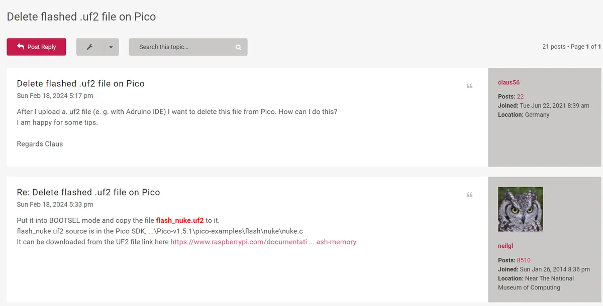
This firmware is also available in the given reference folder: elegance-devkit v1\Reference Materials\Official Materials\Official Firmware
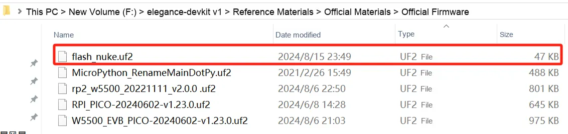
- Flash the MicroPython_RenameMainDotPy.uf2 firmware: If the issue is limited to the
main.pyfile and there is no need to perform a completeflash_nuketo erase the entire flash, you can flash this firmware — it will only delete or rename themain.pyfile without affecting other files stored in the device's file system. This firmware is suitable for flashing when you have important data or code stored in the file system.
The solution is shown in the following link: https://forums.raspberrypi.com/viewtopic.php? f= 146&t= 305432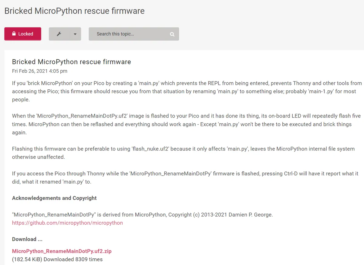
This firmware can also be found in the reference folder we provided: elegance-devkit v1\Reference Materials\Official Materials\Official Firmware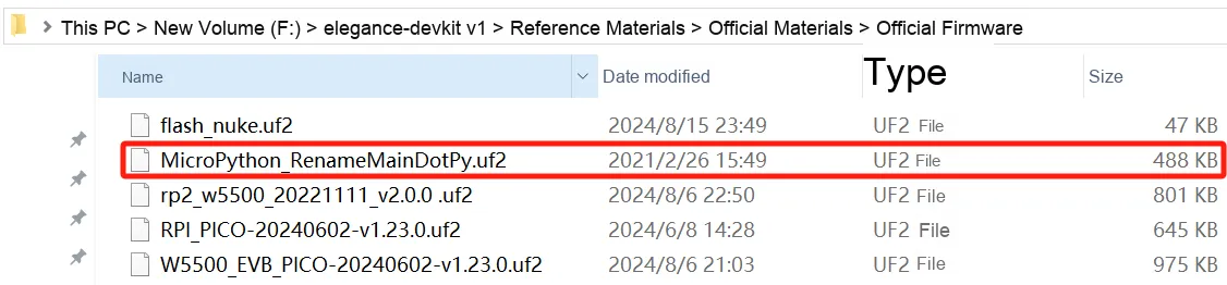
It should be noted that neither of the two firmware versions can clear the boot.py file.
Version Record
Version Number | Modifier | Time | Content |
v1.0.0 | Li Zisheng | 2025/09/18 | Initialize the document, based on MicroPython version v1.23.0. |
v1.1.0 | Li Zisheng | 2026/01/24 | Modified the wiring description table of the watchdog module. |