
Contents
- 1. Hardware Explanation
- 1.1 Introduction to RTC Real-Time Clock
- 1.2 Introduction to the RTC Peripheral in Raspberry Pi Pico
- 1.3 Introduction to the DS1302 Real-Time Clock Chip
- 2. Software Control Method
- 2.1 Constructor of the machine.RTC class
- 2.2 Other Methods of the machine.RTC Class
- 3. Application Examples
- 3.1 Obtain network time and set the RTC real-time clock
- 3.2 Implement a Simple Digital Alarm Clock Using the DS1302 RTC Clock
- References
- Version Record
1. Hardware Explanation
1.1 Introduction to RTC Real-Time Clock
RTC (Real-Time Clock) is a hardware module or chip that can track the current time, and is commonly used in devices requiring precise timekeeping, such as embedded systems, computers, and smart devices. The RTC module can continue keeping time even when the device is powered off, maintaining its timing function by using a battery or a supercapacitor.

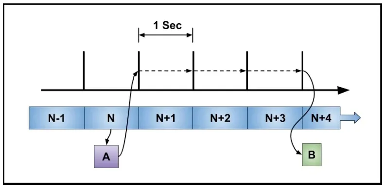
Simply put, the RTC (Real-Time Clock) can be regarded as a timer with a fixed timing interval of 1 second, as shown in the following figure:
An RTC (Real-Time Clock) typically has the following functions:
- Time Keeping: The RTC can record and continuously track the current second, minute, hour, date, month, year and other information.
- Low Power Consumption: Since the RTC module usually operates in low-power mode, it is highly suitable for embedded systems that require long-term operation.
- Alarm function: Many RTC modules support the alarm function, which can generate an interrupt signal at a preset time to trigger certain operations of the system.
- External Power Supply Support: The RTC module is usually equipped with a backup battery or a supercapacitor to ensure that it can continue to operate normally even when the main power supply is disconnected.
It is often used in the following scenarios:
- Timestamp Record: Used to record the time of events, such as Data Acquisition, logging, etc.
- Scheduled Operation: Triggers system operations at a specific time, such as turning a device on or off on a schedule.
- Calendar function: Designed for devices that need to display date and time, such as clocks, calendars, etc.
1.1.1 Basic Structure and Working Principle of RTC
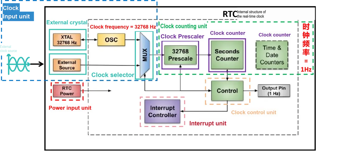
The basic structure of RTC is as follows, including:
- Clock Input Unit: It is responsible for receiving external clock signals, which are typically high-precision clock sources provided by crystal oscillator circuits or external clock sources with a fixed frequency of 32768Hz. We can select the clock source via a multiplexer and feed it into the prescaler.
- Power Input Unit: Responsible for receiving the main power input of the system, and also supports the input of the backup battery to keep the clock running continuously when the main power supply is cut off.
- Interrupt Unit: Provides interrupt signals such as time arrival and alarm triggering, which can be used to wake up the system or trigger specific operations.
- Clock Control Unit: Responsible for setting and controlling the clock, which allows configuration of the current time and date information.
- Clock Counting Unit: The prescaler divides the clock frequency by 32768 (i. e., 2^15) to generate a 1-second clock signal. A basic RTC typically features a second clock counter, which is usually 32 bits or wider; some RTCs are also equipped with dedicated counters to track the time of day and calendar date, and the clock counter stores the counting result in an internal register for access.
Its working principle can be summarized as follows: when the system power supply is on, the RTC crystal oscillator starts to oscillate, and the counter circuit starts counting; the counter circuit increments by 1 every second and updates the time and date information in the register group, and we can obtain or set the current timing value by reading and writing the clock counter.
Meanwhile, when the system is powered off, the RTC (Real-Time Clock) can switch to the backup battery power supply mode to continue keeping time counting; in addition, the RTC supports the alarm function to trigger an interrupt signal at a specific time point.
1.1.2 Accuracy and Error of RTC Real-Time Clock
The typical accuracy specification of crystals used for RTC (Real-Time Clock) usually ranges from ±100 to ±20 ppm (parts per million). This means that the daily time error will be approximately between 8.6 seconds and 1.7 seconds (±100 ppm means that over a runtime of 1 million seconds, the time may be 100 seconds faster or slower; therefore, an error of ±100 ppm will result in an error of approximately ±8.6 seconds per day (i. e., 86400 seconds)). Specifically:
- ±100 ppm indicates a daily time error of ±8.6 seconds
- ±50 ppm indicates a daily time error of ±4.3 seconds
- ±20 ppm indicates a daily time error of ±1.7 seconds
This type of error is determined by the inherent characteristics of the crystal oscillator, including temperature variations, aging effects, and the influence of external circuits. For high-precision applications, crystals with lower ppm values may be selected, and temperature compensation or the use of an external more accurate time source to correct the RTC error may also be taken into account during design.
1.1.3 Internal RTC Real-time Clock and External RTC Real-time Clock
An internal RTC refers to the real-time clock module embedded inside a chip, which is usually driven by the system clock of the MCU (such as a 32.768kHz crystal oscillator) to maintain time counting. Its accuracy is generally low due to the influence of the main chip's clock and temperature, so it is often used in scenarios with low precision requirements.
An external RTC is a dedicated real-time clock chip independent of the MCU. It usually communicates with the MCU via buses such as I2C or SPI, is driven by an independent crystal oscillator (typically a 32.768kHz quartz crystal oscillator), and features a backup power supply design: even when the main power is turned off, it can immediately switch to the backup power supply (commonly a CR2032 coin cell battery) for powering. It also integrates functions including alarm, timing interrupt, and backup SRAM storage, and is widely used in scenarios that require high time accuracy and long-term time information retention.
Here, it should be noted that the RP2040 microcontroller used in the Raspberry Pi Pico does not have a traditional RTC power-off backup function; unlike some MCUs (such as STM32) that have a dedicated VBAT pin to keep the RTC running when power is cut off, once the main power is disconnected, the RTC timing will stop and the time data will be lost.
1.2 Introduction to the RTC Peripheral in Raspberry Pi Pico
In the RTC peripheral of the Raspberry Pi Pico, time is stored in binary form and divided into seven fields:
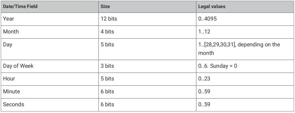
It should be noted that these seven fields are readable and writable, and attention should be paid to the time range during writing; the RTC does not check whether the programmed value falls within this range. An invalid value may lead to unexpected behavior.
Meanwhile, working days are represented as numerical codes starting from Sunday (Sun): Sun= 0, Mon= 1,. .., Sat= 6, and this encoding method is called the mod 7 (i. e., modulo 7) of the ISO 8601 standard. The RTC does not have a built-in calendar function, so it does not automatically calculate the correct day of the week; instead, it simply increments the current value. For example, if the current day is Monday (1), the next cycle will be Tuesday (2), and so on.
We can obtain the current time by reading the RTC_0 register and RTC_1 register:
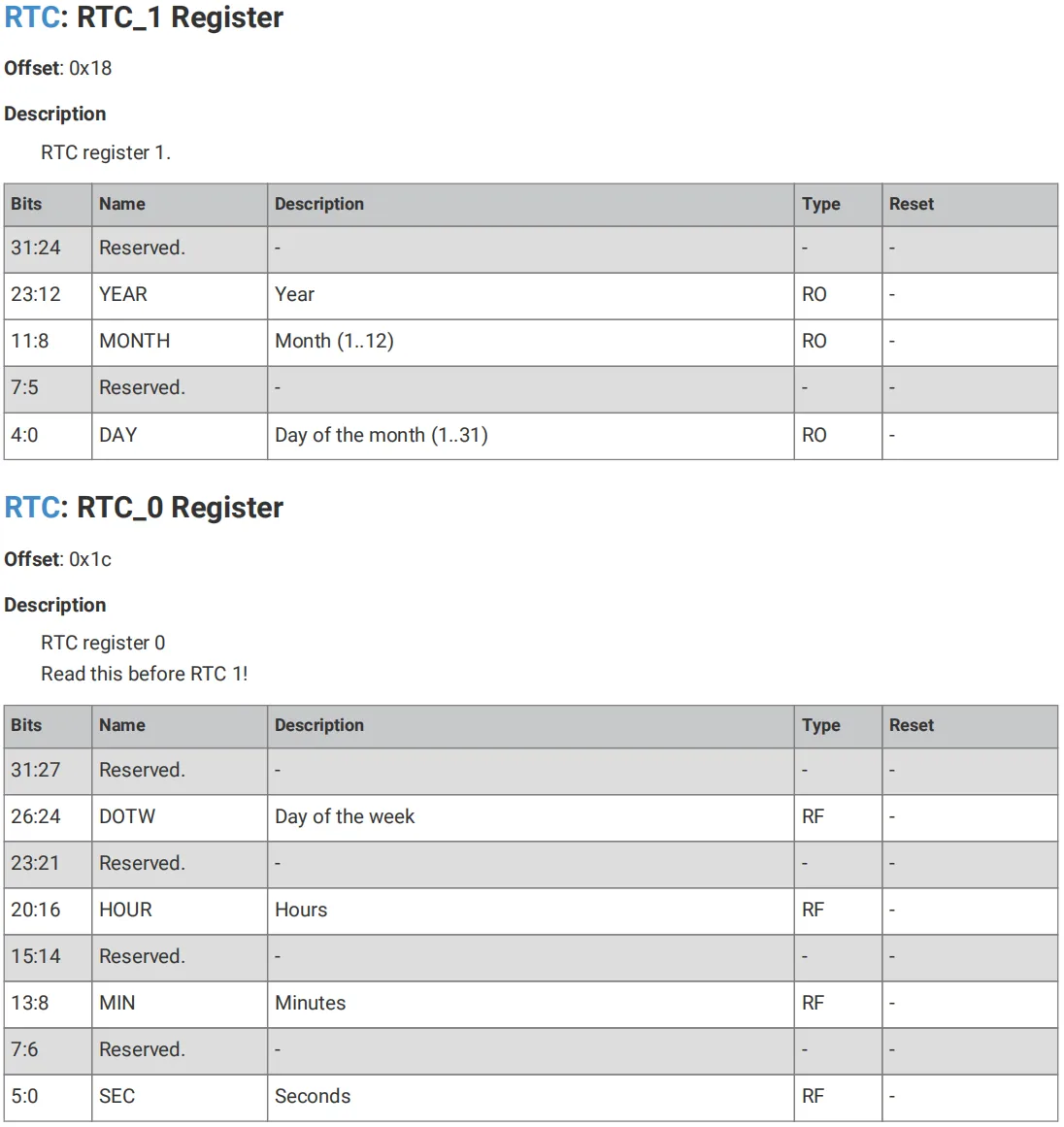
You can also set the current time via the SETUP register:
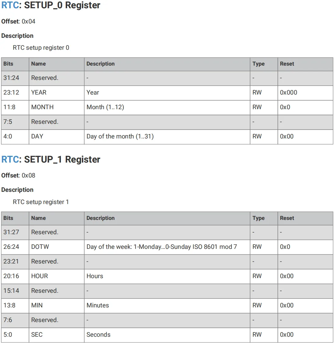
1.2.1 RTC Clock Input
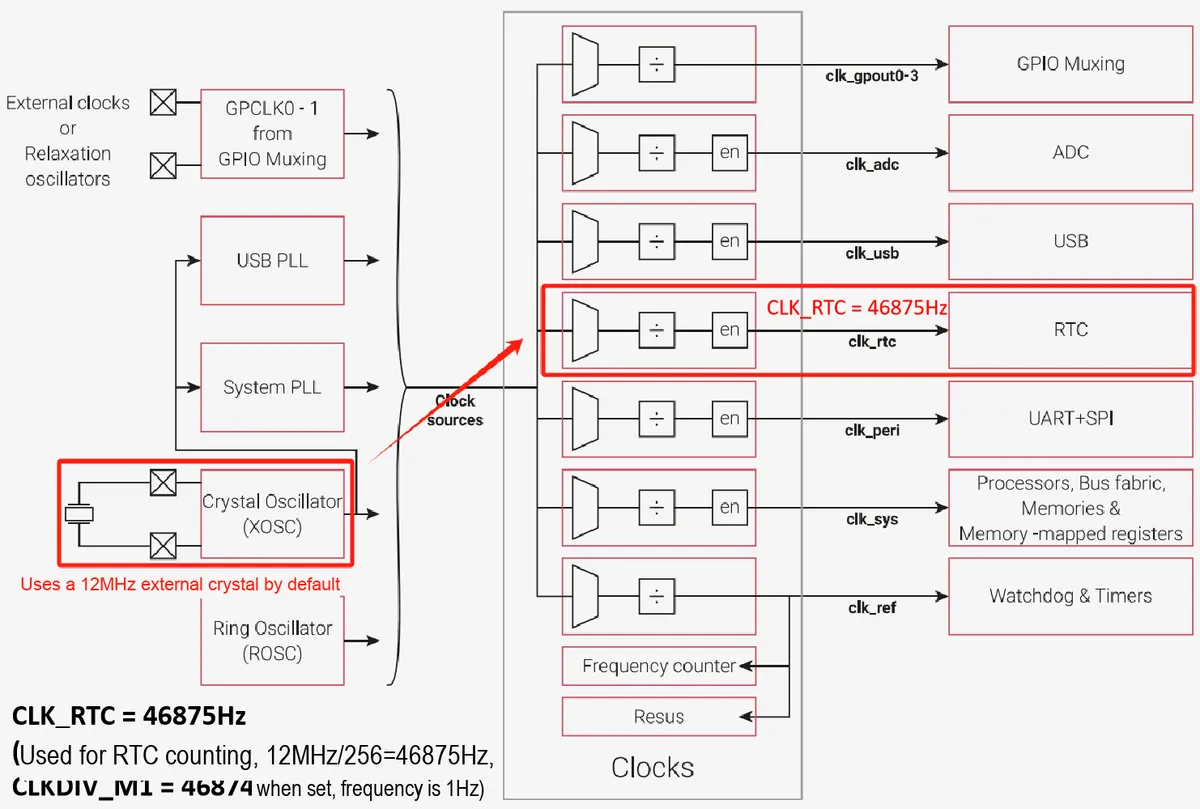
In the RTC peripheral of the RP2040 (Raspberry Pi Pico), the reference clock used is clk_rtc, whose frequency can be any integer in the range from 1 to 65536 Hz. The internal 1 Hz reference clock is generated by an internal clock divider, which divides the frequency of clk_rtc by an integer value. This integer value, after being decremented by 1, is set in the register CLKDIV_M1:
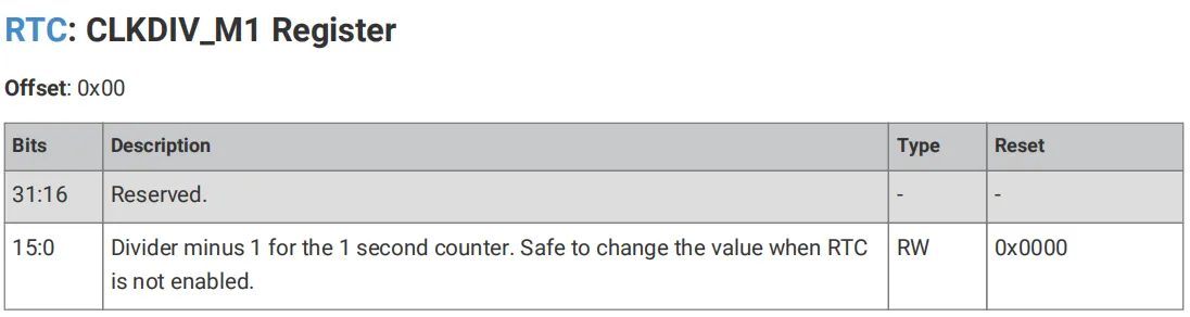
It should be noted that it is not recommended to change the value of RTC when it is enabled. CLKDIV_M1 Doing so will alter the clock frequency of the RTC, which in turn affects the accuracy of time units such as seconds, minutes and hours, leading to deviations in the RTC timekeeping. This is unacceptable for some application scenarios that have extremely high requirements for time accuracy.
clk_rtc can be driven by an internal or external clock source, and can be prescaled via a fractional frequency divider:
- XOSC @ 12MHz / 256 = 46875Hz: To obtain a 1Hz reference clock at this point,
CLKDIV_M1should be set to 46874, and the 12MHz external crystal oscillator is used by default. - External reference from GPS: In this case, the GPS generates a pulse once per second,
clk_rtcis configured to run from the GPIN0 clock source of GPIO pin 20, at which point the divider ofclk_rtcis 1, and the internal RTC clock divider is also 1 (i. e.,CLKDIV_M1is 0)
All read and write operations on RTC registers are performed in the processor clock domain clk_sys, and data is synchronized back and forth between different clock domains. This means that when writing to an RTC register, the operation does not take effect immediately; instead, it takes two clk_rtc cycles to complete synchronization and update. Therefore, this must be given special consideration when using a slower reference clock, such as 1Hz. A slower clock speed will cause delays in data updates, so when designing and implementing RTC functionality, it is necessary to ensure that this does not adversely affect the time accuracy of the system.
Here, the crystal oscillator used by the Raspberry Pi Pico is a 12MHz SMD crystal oscillator manufactured by AEL (Advanced Electronics and Logistics):
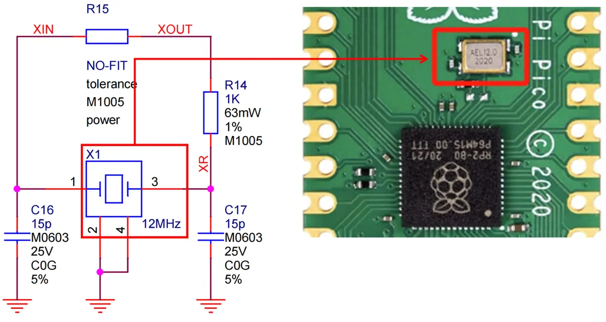
We have not found the specific datasheet, but we have made a comparison with the domestic alternative YXC X322512MSB4SI crystal oscillator:
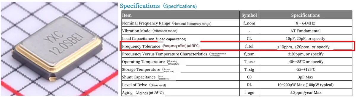
Its frequency accuracy is expected to be no greater than ±30 ppm, which means the maximum time error within one day may be approximately 2.6 seconds.
1.2.2 Leap Year Check
In the SETUP_0 register of the RTC, if the YEAR data bit of the year value is divisible by 4, it will be detected as a leap year. In this case, the day after February 28 will automatically become February 29 instead of March 1:
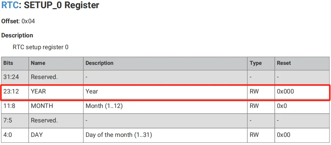
However, this simple rule of adding a leap year every 4 years is not always correct, and does not apply to century years such as 2100, for example. To address this issue, the RTC provides a CTRL.FORCE_NOTLEAPYEAR bit that is used to forcibly disable leap year checking:
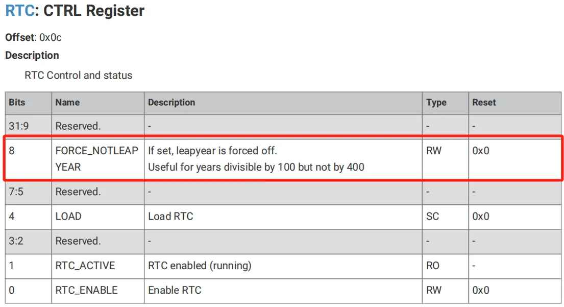
Specifically, the RTC only performs a leap year check at 23:59:59 on February 28. If a developer is certain that a given year is not a leap year, they can set the FORCE_NOTLEAPYEAR bit before that point in time to force February 29 to be skipped, directly advancing the date to March 1.
This feature of forcibly disabling the leap year check is very useful, especially for years after March 1,2096. Because before 23:59:59 on February 28,2100, developers need to set the FORCE_NOTLEAPYEAR bit in advance to ensure that the RTC can accurately handle non-leap year scenarios and avoid the delay problems caused by clock domain crossing.
1.2.3 Interrupt Function
RTC can generate an interrupt at a configured time point. There is a global enable bit MATCH_ENA in the IRQ_SETUP_0 register, which is used to enable this interrupt function:
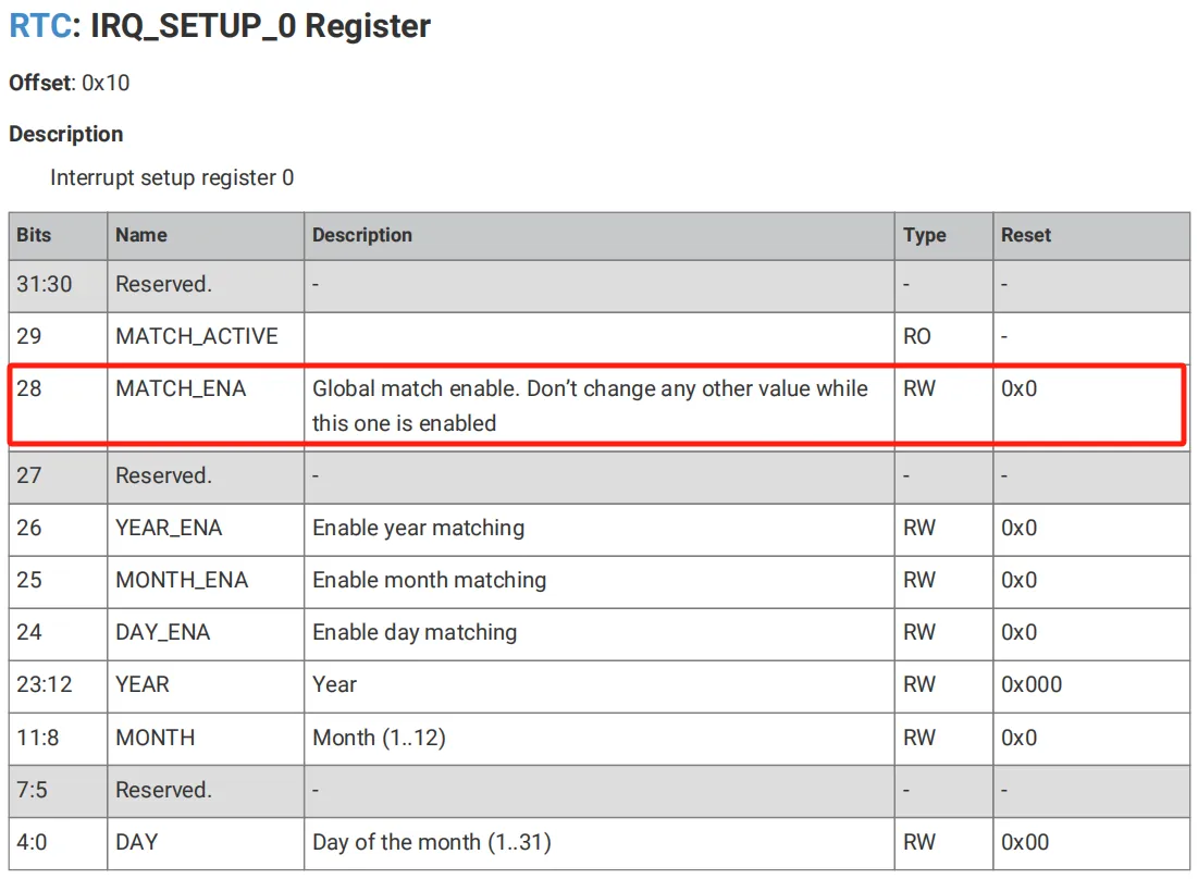
Meanwhile, the RTC also provides individual enable bits for each time field (year, month, day, weekday, hour, minute, second). Developers can selectively enable the interrupt of specific time fields to generate repetitive interrupts at a specified time:
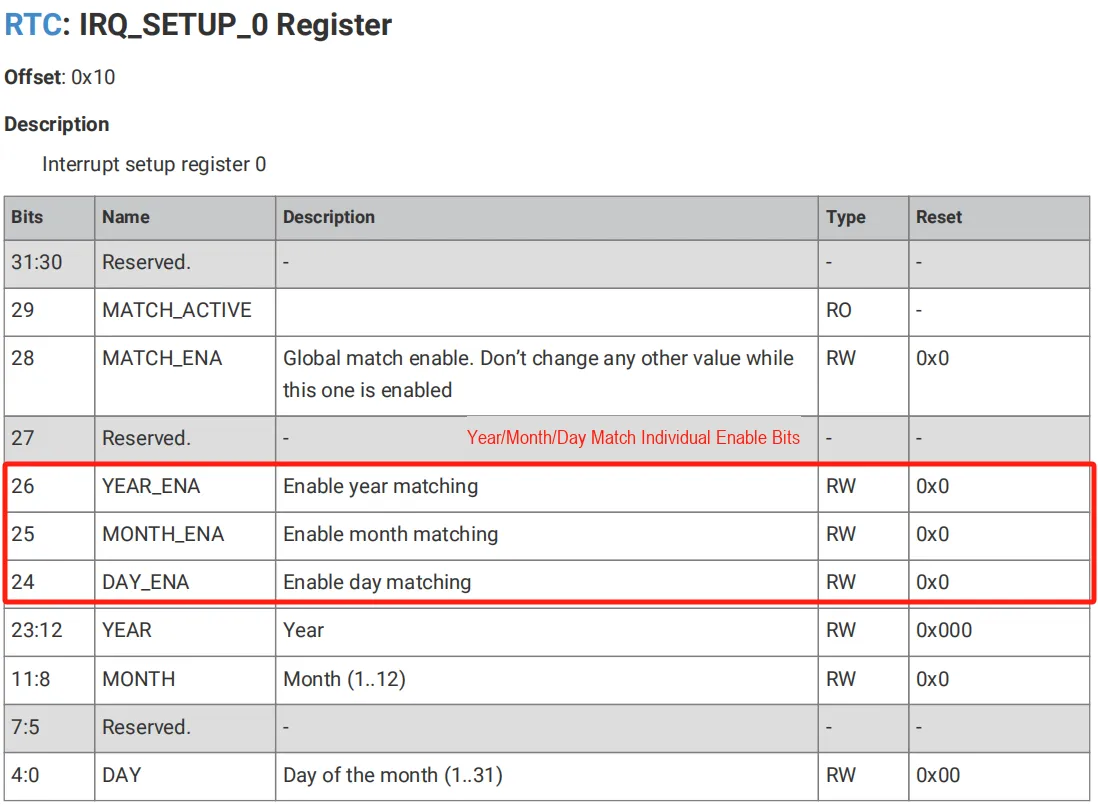
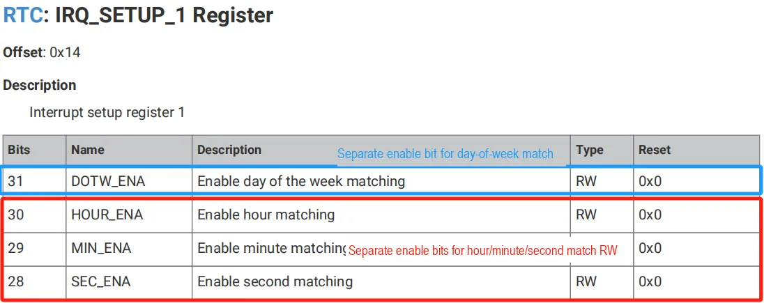
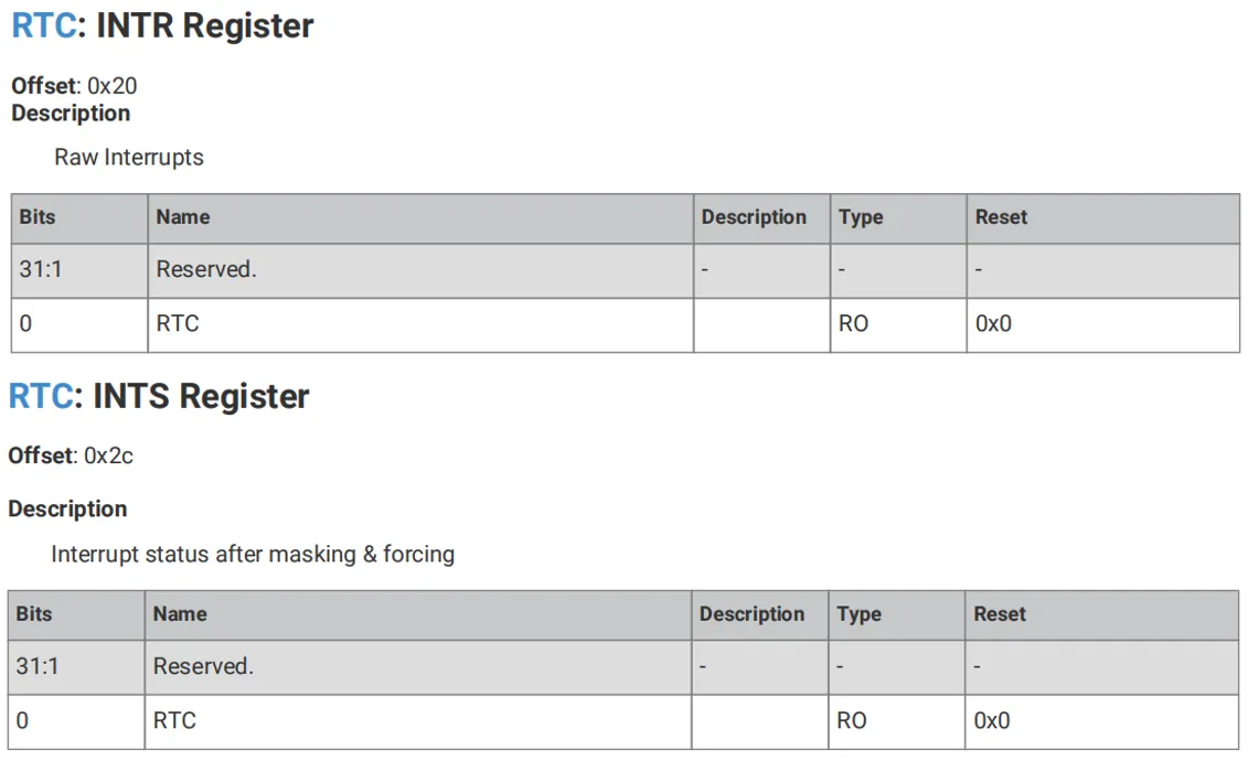
Meanwhile, we can obtain the raw RTC interrupt by reading the INTR register, and get the masked RTC interrupt by reading the INTS register:
You can also forcibly trigger an RTC interrupt via the INTF register and enable the RTC interrupt via the INTE register:
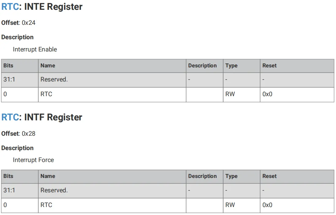
When an interrupt condition is met, the RTC sends an interrupt signal to the processor, and simultaneously wakes up both the ROSC (Ring Oscillator) and XOSC (Crystal Oscillator) from their sleep modes. In general, the interrupt function of the RTC is extremely flexible and powerful. Developers can selectively enable interrupts for specific time fields according to actual requirements to implement functions such as scheduled tasks and alarms. Additionally, RTC interrupts can also be used to wake up the processor and oscillators, thereby reducing system power consumption.
1.2.4 RTC Wake-up Function
When the device enters the low-power mode, the RTC peripheral can continue to operate and trigger an interrupt when the preset time is reached, thereby waking up the device:
- The Raspberry Pi Pico is in sleep mode (
Sleep Mode):- In this mode, the processor will enter a sleep state, and the unused clocks in the chip will be stopped.
- The chip can be configured to only run
clk_rtc(a slow RTC reference clock) and a small portion of logic to allow processor wake-up when in sleep mode - The processor will be woken up from the sleep mode when the RTC alarm interrupt is triggered.
- The Raspberry Pi Pico is in sleep mode (
Dormant Mode):- In this mode, all clocks in the chip will be stopped.
- To wake the chip from the sleep mode, the following steps must be completed:
RTCmust be configured to use an external reference clock (provided via a GPIO pin)- Configure the RTC to run on an external reference clock
- If the processor is operating under
PLL(Phase-Locked Loop) clock, it needs to be switched to use XOSC/ROSC (External Oscillator/Internal Oscillator) - Turn off all PLLs
- Configure
RTCto set the desired wake-up time (one-time wake-up or periodic wake-up) - (Optional) Turn off most memory
- invoke
DORMANTmode
1.3 Introduction to the DS1302 Real-Time Clock Chip
DS1302 is a widely used real-time clock (RTC) chip that can track time (seconds, minutes, hours, days, dates, months and years) and features leap year compensation valid up to the year 2100. It is commonly applied in electronic projects requiring precise timekeeping, such as data loggers, clocks, timers and automation systems.
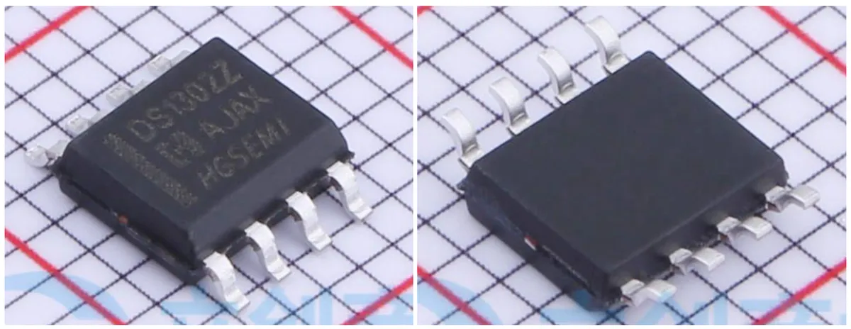
The main features are as follows:
- Low Power Consumption: In standby mode, the DS1302 features extremely low current draw, making it ideal for battery-powered applications.
- Serial Interface: A simple three-wire serial interface is used for data communication, which reduces the number of pins required.
- RAM: It has a built-in 31-byte RAM that can be used to store user data
- Dual power supply design: Supports main power supply and backup power supply, ensuring that the clock can continue to operate even when the main power supply is disconnected
- Temperature Compensation: With an external crystal oscillator, the DS1302 can achieve high time accuracy, typically ±1 second per day
- Calendar function: It can count seconds, minutes, hours, days, weeks, months, and years with leap year compensation; the clock supports either the 24-hour format or the 12-hour format with AM (Ante Meridiem) / PM (Post Meridiem) indicators.
- Wide operating power supply voltage range: 2.0V ~ 5.5V
The DS1302 communicates with the microcontroller via three lines (I/O data line, SCLK clock line, RST reset line), and a typical application example diagram is shown below:
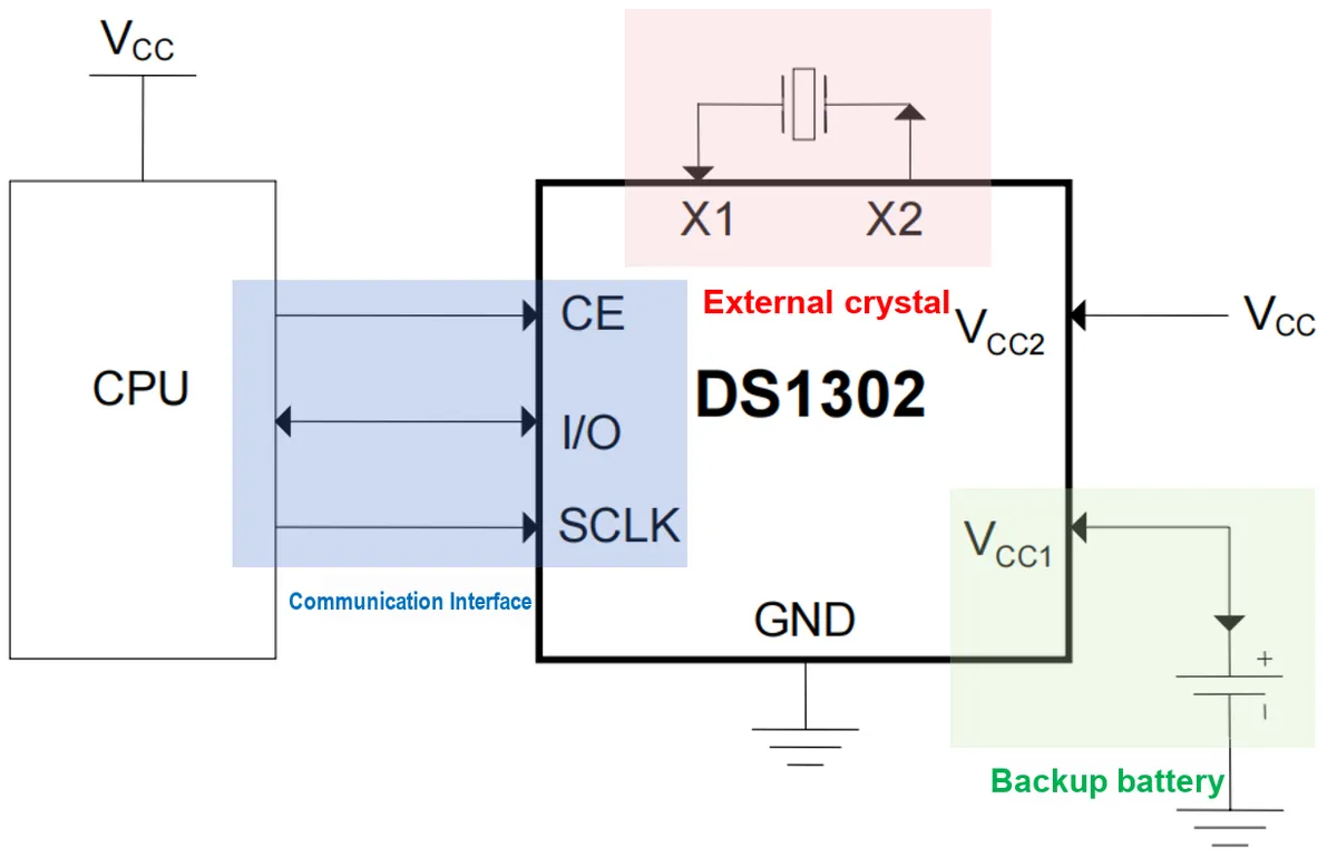
Here, we typically connect the VCC2 pin of the DS1302 to a CR2032 coin cell battery to keep the clock running when the main power supply fails; meanwhile, the DS1302 requires an external crystal oscillator (usually a 32.768 kHz passive crystal) to provide a stable clock signal.
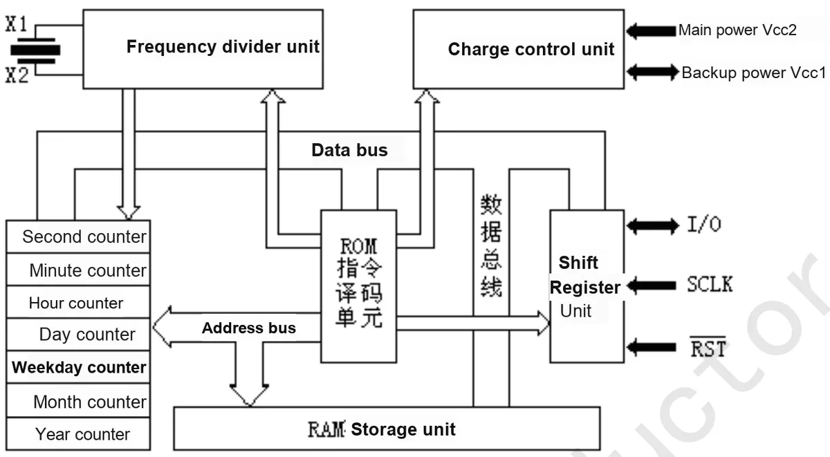
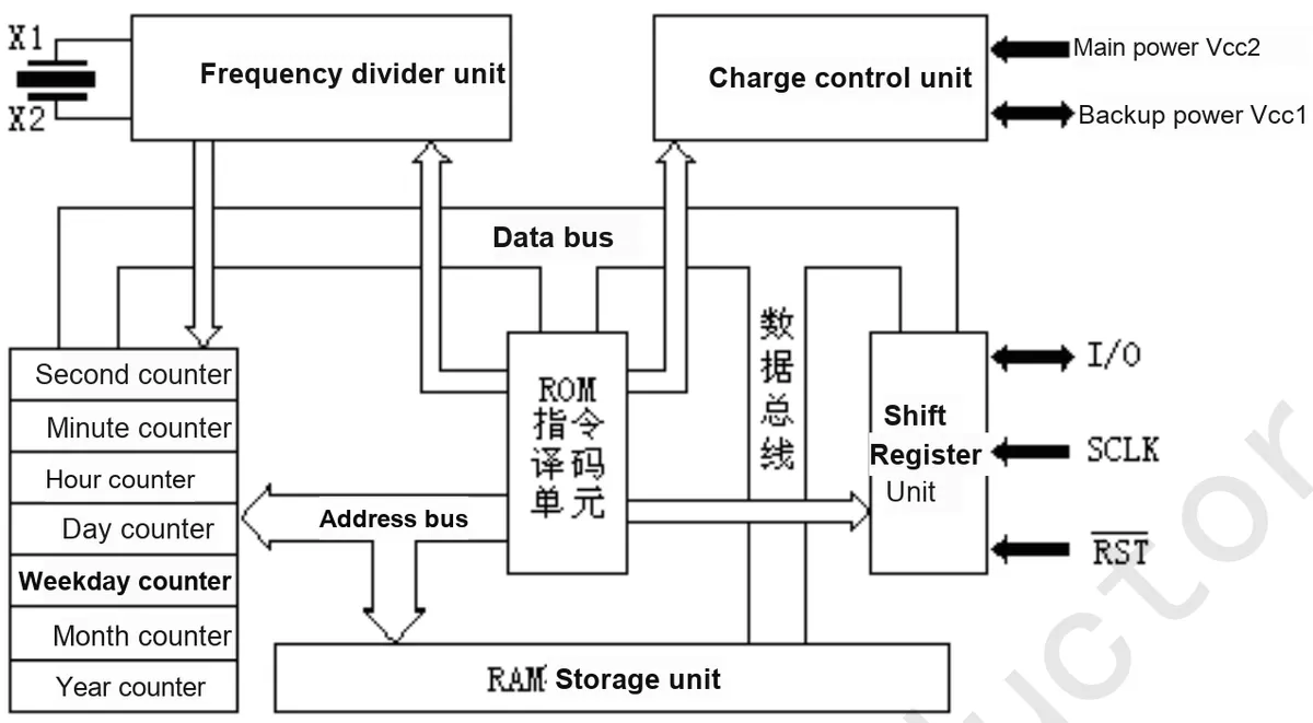
The above is the internal block diagram of the DS1302 chip. The core working part of the DS1302 is its multiple counters, which can track seconds, minutes, hours, dates, months and years under the clock signal input from the frequency divider unit. Meanwhile, the built-in RAM of the DS1302 can be used to store some non-volatile data, which facilitates maintaining the state after the system restarts.
The pin diagram and typical application circuit schematic of the DS1302 chip are shown as follows:
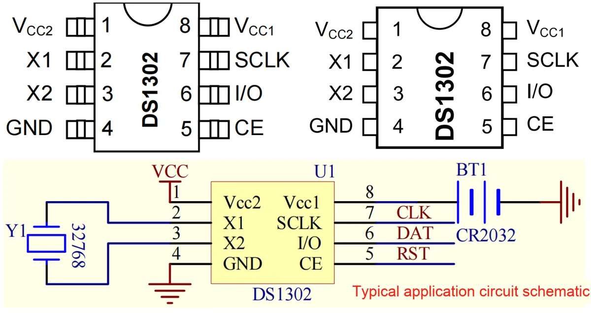
The names and functions of each pin are as follows:
Pin Number | Pin Name | Function |
1 | VCC2 | Main power supply pin, used in dual-power configuration. VCC1 is connected to a backup power source to retain time and date when the main power is absent. The DS1302 is powered by the higher of VCC1 and VCC2.
|
2 | X1 | These are the connection pins for a standard 32.768kHz crystal; the internal oscillator is designed to operate with a crystal that has a specified load capacitance of 6pF. The DS1302 can also be driven by an external 32.768kHz oscillator, in which case the X1 pin is connected to the external oscillator signal and the X2 pin is left floating. |
3 | X2 | Used in conjunction with the X1 pin to connect a 32.768kHz crystal oscillator. |
4 | GND | Ground pin, connected to power ground. |
5 | CE/RST | Input pin: The CE signal must be pulled high during read or write operations, and this pin is equipped with an internal 40kΩ pull-down resistor to ground. |
6 | I/O | The I/O pin is a bidirectional data pin for the 3-wire interface, featuring an internal typical 40kΩ pull-down resistor to ground. |
7 | SCLK | SCLK is used to synchronize data transmission on the serial interface, and features an internal pull-down resistor (typical value: 40 kΩ) connected to ground. |
8 | VCC1 | Backup power input pin. |
The DS1302 chip uses command bytes to control the reading and writing of data. The format and functions of the command bytes are as follows:

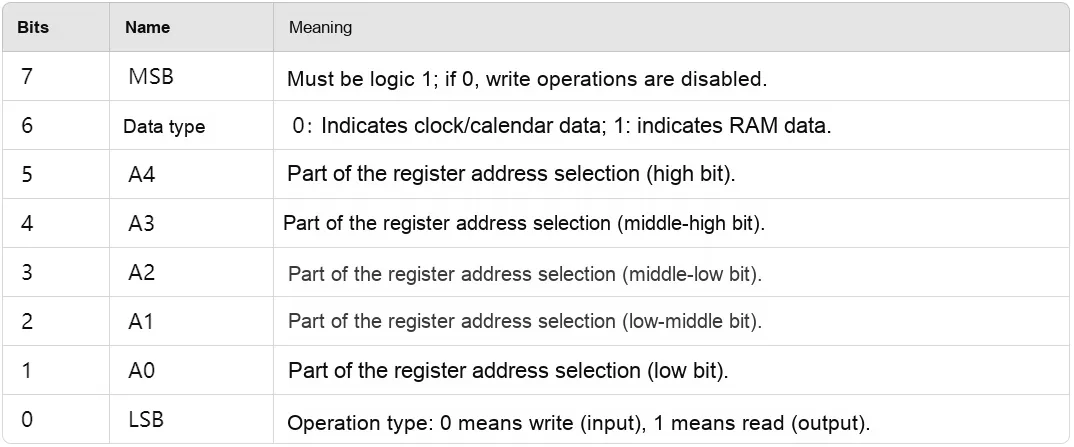
When communicating with the DS1306 chip via the communication interface, we first need to pull the RST signal line high. Under the control of each SCLK pulse, the shift register serially receives an 8-bit command byte; data is input through the I/O pin, and meanwhile the received command byte undergoes serial-to-parallel conversion in the shift register. The shift register sends the converted command byte to the ROM instruction decoding unit, where the ROM parses the command byte to determine the address of the internal register to be accessed and the read/write status.
After 8 SCLK cycles of inputting command bytes to the microcontroller, the DS1302 chip outputs 8 data bits in the subsequent 8 SCLK cycles:
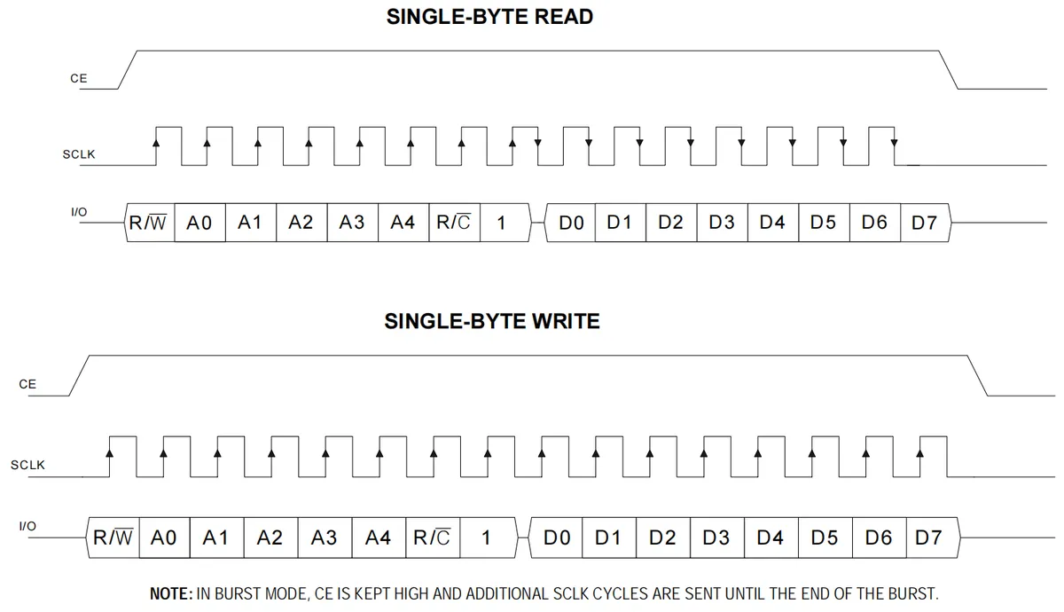
Among them, when the CE pin is at a high level, all data transmissions are initiated; it controls both access to the shift register and the termination of data transmission. The input data must be valid on the rising edge of the clock, while the output data is output on the falling edge. Upon power-up, the CE pin needs to be at a low level, and when driving the CE pin to a high level, the SCLK pin must be at a low level.
Through consecutive SCLK pulses, the system can read and write multiple data bytes (up to 248 bytes) in a single transaction, such as those in calendar, clock registers or RAM cells. By setting address bits 1 to 5 to high level, the multi-byte read/write mode can be initiated; in this mode, bit 6 is used to specify the operation type (clock/calendar or RAM), while bit 0 specifies the read/write direction (read or write):
- Write Clock Registers: In multi-byte write operations, the first 8 registers (addresses 0 to 7) must be written in sequence. This is because the data structure of the clock registers is continuous; if the full 8 registers are not written completely, time data inconsistency may occur.
- Write to RAM registers: For RAM registers, users do not need to write all 31 bytes; only the bytes that require updating need to be written.
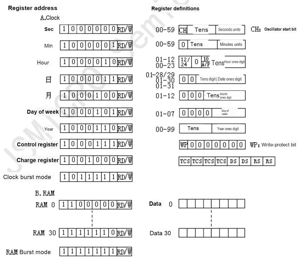
The definitions and addresses of the internal registers of the DS1302 chip are as follows:
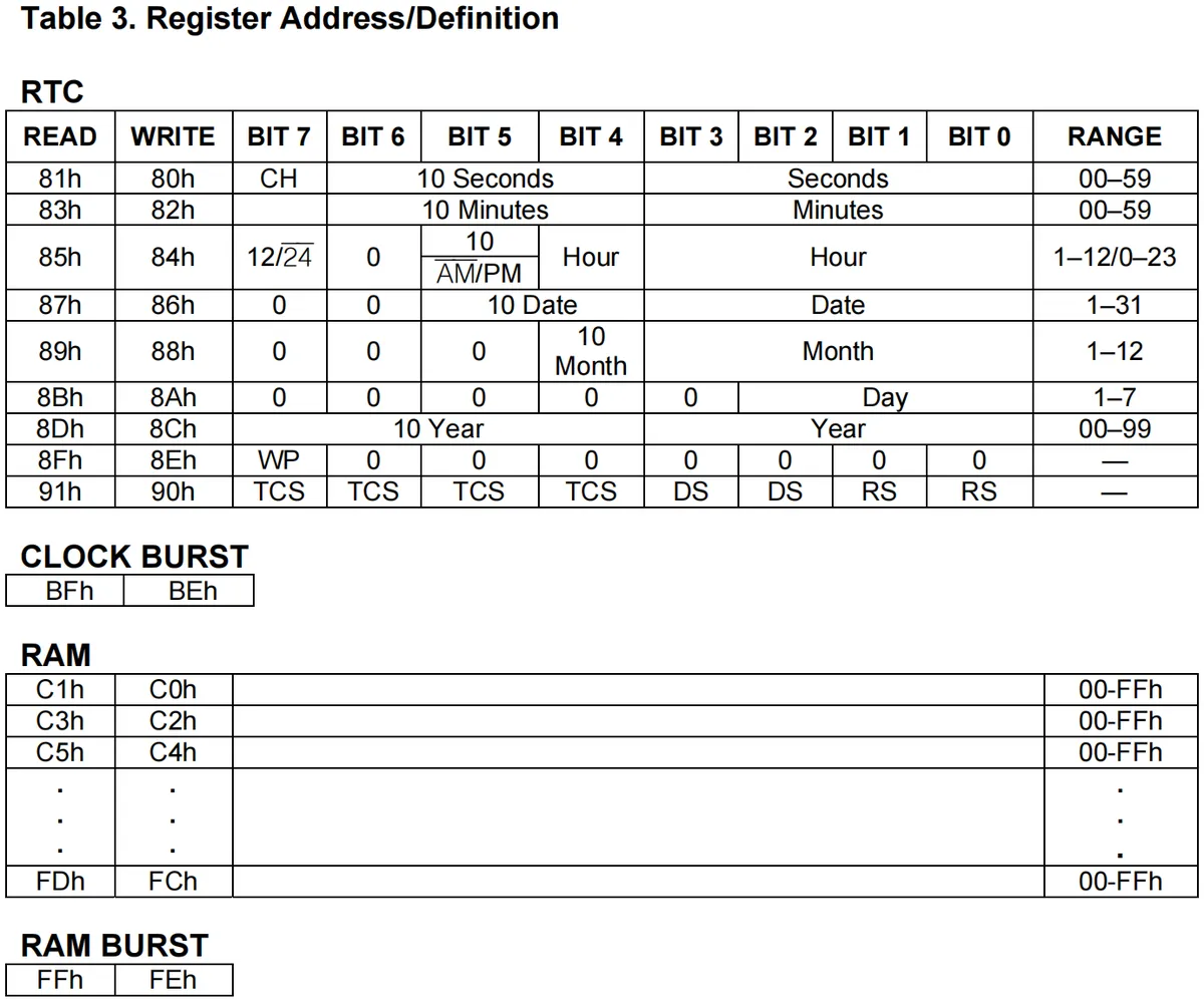
It can be divided into the following sections:
- Clock/Calendar Registers: Used to store time and date information, these registers have addresses ranging from 81h to 8Dh, covering fields such as seconds, minutes, hours, date, month, day of the week, and year; each of these fields is further divided into a tens digit field and a units digit field. Taking the seconds field as an example, it consists of the
10 Secondstens digit field and theSecondsunits digit field. Here, the DS1302 uses Binary-Coded Decimal (BCD) code to represent time and date information. Assuming the current time is "12:34:56", in the registers of the DS1302: the seconds value (56) is 01010110, the minutes value (34) is 00110100, and the hours value (12) is 00010010.- Seconds Register Field: Bit 7 is defined as the clock halt bit. When this bit is set to logic 1, the clock oscillator stops, and the DS1302 is placed into a low-power backup mode with a power consumption of less than 100 nanoamps; when this bit is written to logic 0, the clock will start.
- Hour Register Field: The DS1302 chip can operate in either 12-hour or 24-hour mode, and the mode selection is controlled by the 7th bit of the hour register field. Whenever switching between the 12-hour and 24-hour modes, the hour data must be reinitialized:
- When set to logic high (1), the 12-hour mode is selected; in the 12-hour mode, bit 5 indicates the AM/PM status
- When set to logic low (0), the 24-hour mode is selected, and bit 5 is used as the second tens digit of the hour, representing the hour range from 20 to 23
- Control Register: The control register (
8Fh) is used to configure the write protection function of the chip. Bit 7 is the write protection bit: when set to 1, writing is prohibited; when set to 0, writing is allowed, which ensures that the data stored in the chip can be protected when necessary. It should be noted that the WP bit should be cleared before attempting to write to the device. - Charge Register: The Trickle Charge Register (
91h) controls the trickle charge characteristics of the DS1302. Only the 1010 mode enables the trickle charger to operate, while all other modes disable it. This register is primarily designed to ensure that the battery can be charged in a safe and efficient manner when the device's power supply is interrupted. It is not commonly used, so it will not be discussed in detail here. - Built-in RAM: The DS1302 provides 31 bytes of RAM registers, with the address ranging from
C0htoFDh. Users can use these registers to store arbitrary data, and the value of each RAM register can range from 00 to FFh. - Clock/Calendar Multi-byte (Burst) Registers: The multi-byte operating mode of the clock/calendar allows users to read and write multiple registers consecutively to simplify data transmission; in this mode, users can start from bit 0 of address 0 to sequentially read or write the first 8 clock/calendar registers.
- RAM Multi-byte (Burst) Register: The multi-byte operating mode of RAM allows users to sequentially read or write up to 31 bytes of RAM registers. In this mode, data is continuously transmitted starting from bit 0 of address 0, eliminating the need for users to access individual registers one by one.
Here, the register address corresponds to bits 7 to 1 in the command byte, as shown in the following figure:
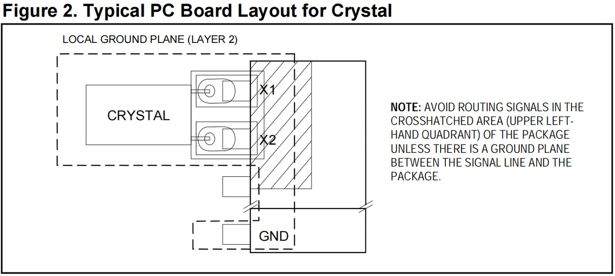
Here, when configuring the external crystal oscillator for the DS1302 chip, attention should be paid to ground shielding during PCB routing: enclose the signal lines of the crystal oscillator (such as pins X1 and X2) within the grounding area as much as possible, which can form a "ground loop" to help suppress electromagnetic interference, as shown in the figure below:
2. Software Control Method
2.1 Constructor of the machine.RTC class
The constructor of the machine.RTC class is as follows:
class machine.RTC(id=0, ...)
Construct an RTC real-time clock object with the given parameters
The parameters are defined as follows:
- id - This parameter is used to distinguish multiple RTC devices or instances:
- id= 0 : Select the first RTC instance or the default RTC configuration.
- id= 1: Select the second RTC instance (if hardware supports multiple RTC instances)
2.2 Other Methods of the machine.RTC Class
The machine.RTC class has other methods as well:
Method | Description |
RTC.datetime([datetimetuple]) | Get or set the date and time of the RTC:
|
RTC.init(datetime) | Raspberry Pi Pico MicroPython v1.23.0 is unavailable Initialize the RTC, and the parameters are defined as follows:
|
RTC.now() | Raspberry Pi Pico MicroPython v1.23.0 is unavailable Get the current date and time tuple |
RTC.deinit() | Raspberry Pi Pico MicroPython v1.23.0 is unavailable Reset the RTC to the time of January 1,2015 and restart its operation |
RTC.alarm(id, time, *, repeat=False) | Raspberry Pi Pico MicroPython v1.23.0 is unavailable Set the RTC alarm, and the parameters are defined as follows:
|
RTC.alarm_left(alarm_id=0) | Raspberry Pi Pico MicroPython v1.23.0 is unavailable Get the remaining milliseconds before the alarm expires |
RTC.cancel(alarm_id=0) | Raspberry Pi Pico MicroPython v1.23.0 is unavailable Cancel the running alarm clock |
RTC.irq(*, trigger, handler=None, wake=machine.IDLE) | Raspberry Pi Pico MicroPython v1.23.0 is unavailable Create an interrupt object triggered by the real-time clock alarm, and the meanings of the parameters are as follows:
|
When you connect a Raspberry Pi Pico and run the dir command, you will find that most functions of the built-in RTC are unavailable. If you need to use the RTC's wake-up and alarm functions in a project, you can only achieve this by programming with the Pico SDK or using an external RTC chip.

3. Application Examples
3.1 Obtain network time and set the RTC real-time clock
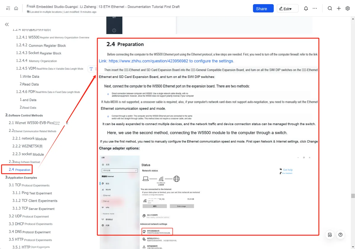
First, we need to connect the computer to the Fengya No. 1 Board - Ethernet and SD Card Expansion Board. For the specific connection process, you can refer to the content in the ETH Ethernet chapter of our textbook (note that when conducting this experiment, you need to connect the Ethernet port on the Fengya No. 1 Board - Ethernet and SD Card Expansion Board to the router):
NTP (Network Time Protocol) servers are used to provide precise time synchronization services. NTP servers can synchronize network time to a standard time source, thereby ensuring that the time on the device remains consistent with Coordinated Universal Time (UTC).
The commonly used public NTP server addresses are as follows:
NTP server address | NTP Server Name |
ntp.ntsc.ac.cn | National Time Service Center of China |
cn.ntp.org.cn | China Time Service |
pool.ntp.org | Globally distributed NTP server pools |
time.google.com | NTP servers provided by Google |
time.windows.com | NTP server provided by Microsoft |
ntp1.aliyun.com | NTP servers provided by Alibaba Cloud |
Here, our primary NTP server of choice is the public NTP time server operated by China Time Service, with the address ' cn.ntp.org.cn '. Before selecting an NTP server, we need to run a ping test on the address to ensure the connection is valid.
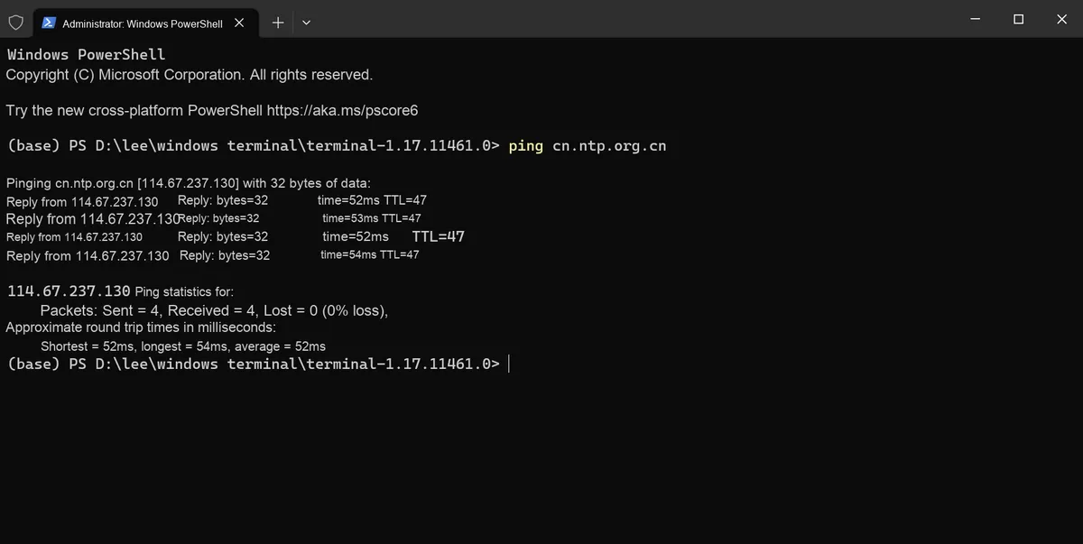
3.1 Application Experiment Ping Test.mp4 514 KB
The following code can be found in the material package we provide, in the elegance-devkit v1\Demo\50 RTC_NTP folder.
In the following code, we obtain the time from the NTP server and set the RTC real-time clock. Meanwhile, in the main loop, we print the current time of the RTC every second. The sample code is as follows:
# Python env   : MicroPython v1.23.0 on Wiznet W5500
# -*- coding: utf-8 -*-
# @Time    : 2024/8/14 PM 2:30
# @Author  : Li Qingshui
# @File    : main.py
# @Description : Usage of the RTC real-time clock class, get the time from an NTP server to set the RTC real-time clock

# ======================================== Import Modules ========================================

# Import hardware-related modules
from machine import Pin,SPI,RTC
# Import time-related modules
import time
# Import network-related modules
import network
import socket
# Import the module for accessing and setting the system time
import ntptime

# ======================================== Global Variables ============================================

# Device IP address
ip = '192.168.1.20'
sn = '255.255.255.0'
gw = '192.168.1.1'
dns = '114.114.114.114'

# Tuple object used for the network connection
netinfo = (ip, sn, gw, dns)

# Set multiple alternative NTP servers
ntp_servers = [
    'cn.ntp.org.cn',
    'ntp.aliyun.com',
    'time1.cloud.tencent.com',
    'pool.ntp.org'
]

# NTP server currently in use
current_ntp_server = 0

# ======================================== Functions ============================================

# Initialize the network connection
def w5x00_init() -> network.WIZNET5K:
    """
    Initialize the WIZNET5K Ethernet module, communicate over the SPI interface, and set a static IP address.

    Args:
        None: No parameters.

    Returns:
        network.WIZNET5K: The initialized WIZNET5K Ethernet instance.

    Raises:
        OSError: If the network interface fails to connect.
    """

    # Declare global variables
    global netinfo

    # Initialize the SPI object
    spi = SPI(0, 2_000_000, mosi=Pin(19), miso=Pin(16), sck=Pin(18))
    # Instantiate the network.WIZNET5K class, passing in the chip select pin CS and reset pin RST
    nic = network.WIZNET5K(spi, Pin(17), Pin(20))
    # Activate the network interface
    nic.active(True)

    try:
        print("\r\nConfiguring DHCP")
        # Try to use DHCP to dynamically obtain network configuration such as IP address, subnet mask, gateway and DNS server
        nic.ifconfig('dhcp')
    except:
        print("\r\nDHCP fails, use static configuration")
        # If DHCP fails, use the static IP address configuration
        nic.ifconfig(netinfo)

    # Wait for the network connection
    max_attempts = 10
    attempt = 0
    while not nic.isconnected() and attempt < max_attempts:
        attempt += 1
        print(f"Waiting for network connection... Attempt {attempt}/{max_attempts}")
        time.sleep(1)
        # Output register information
        print(nic.regs())

    if not nic.isconnected():
        raise OSError("Failed to establish network connection")

    # Print the configured IP address
    print('ip :', nic.ifconfig()[0])
    print('sn :', nic.ifconfig()[1])
    print('gw :', nic.ifconfig()[2])
    print('dns:', nic.ifconfig()[3])

    # Test DNS resolution
    try:
        addr = socket.getaddrinfo(ntp_servers[0], 80)[0][-1]
        print(f"DNS resolution test successful: {ntp_servers[0]} -> {addr[0]}")
    except Exception as e:
        print(f"DNS resolution test failed: {e}")

    return nic

# Modify the timeout setting of ntptime
def set_ntptime_timeout(timeout_ms: int) -> None:
    """
    Modify the timeout setting of the ntptime module to ensure it waits correctly for a response when the network is delayed.

    Args:
        timeout_ms: Timeout, in milliseconds.

    Returns:
        None: No return value.
    """
    # If the ntptime module has a timeout attribute, set it directly
    if hasattr(ntptime, 'timeout'):
        ntptime.timeout = timeout_ms
    else:
        # Otherwise, try modifying the internal implementation
        import usocket as socket
        def _ntp_time(host):
            NTP_DELTA = 2208988800
            NTP_QUERY = bytearray(48)
            NTP_QUERY[0] = 0x1B
            addr = socket.getaddrinfo(host, 123)[0][-1]
            s = socket.socket(socket.AF_INET, socket.SOCK_DGRAM)
            try:
                s.settimeout(timeout_ms / 1000)
                s.sendto(NTP_QUERY, addr)
                msg = s.recv(48)
            finally:
                s.close()
            val = int.from_bytes(msg[40:44], 'big')
            return val - NTP_DELTA

        # Replace the time function of ntptime
        ntptime.time = _ntp_time

# Get network time
def get_network_time() -> time.struct_time:
    """
    Get the network time from an NTP server and set the system clock.
    Also convert the time to Beijing time (UTC+8).

    Args:
        None: No parameters.

    Returns:
        time.struct_time: The current local time.

    Raises:
        Exception: If getting the network time fails, it keeps retrying in a loop.
    """
    global current_ntp_server, ntp_servers

    # Set the NTP timeout to 5 seconds
    set_ntptime_timeout(5000)

    max_retries = 5
    retry_count = 0

    while retry_count < max_retries:
        try:
            # Switch to the current NTP server
            ntptime.host = ntp_servers[current_ntp_server]
            print(f"Trying to sync time with {ntptime.host}...")

            # Get the time from the NTP server and set the system clock; note that it is UTC time
            ntptime.settime()

            # Get the current local time
            nowtime = time.localtime()
            # Convert to Beijing time (UTC+8)
            beijing_time = convert_to_beijing_time(nowtime)
            # Print the current time
            print(f'Successfully synced with {ntptime.host}. Current time: {beijing_time}')

            # Set the RTC clock
            rtc.datetime((
                beijing_time[0], beijing_time[1], beijing_time[2],
                beijing_time[6], beijing_time[3], beijing_time[4],
                beijing_time[5], 0
            ))
            print("RTC time set successfully")

            return beijing_time

        except Exception as e:
            print(f'Failed to get time from {ntptime.host}: {e}')
            retry_count += 1

            # Switch to the next NTP server
            current_ntp_server = (current_ntp_server + 1) % len(ntp_servers)

            # Wait a while before retrying
            time.sleep(2)

    # If all attempts fail, raise an exception
    raise Exception("All NTP servers failed to respond after multiple attempts")

# Convert UTC time to Beijing time (UTC+8)
def convert_to_beijing_time(utc_time: time.struct_time) -> time.struct_time:
    """
    Convert UTC time to Beijing time (UTC+8).

    Args:
        utc_time (time.struct_time): UTC time tuple.

    Returns:
        time.struct_time: Beijing time tuple.
    """
    # Convert the time tuple to a timestamp (seconds)
    utc_timestamp = time.mktime(utc_time)
    # Add 8 hours (8 * 3600 seconds)
    beijing_timestamp = utc_timestamp + 8 * 3600
    # Convert back to a time tuple
    return time.localtime(beijing_timestamp)

# Convert RTC time to a format compatible with time.localtime()
def rtc_to_localtime(rtc_time: tuple) -> tuple:
    """
    Convert the 8-tuple returned by RTC.datetime() to an 8-tuple format compatible with time.localtime().

    Args:
        rtc_time (tuple): The 8-tuple returned by RTC.datetime() (year, month, day, weekday, hour, minute, second, subseconds).

    Returns:
        tuple: 8-tuple format (year, month, day, hour, minute, second, weekday, yearday).
    """
    # Ignore subseconds
    year, month, day, weekday, hour, minute, second, _ = rtc_time
    # Calculate the timestamp
    yearday = time.mktime((year, month, day, hour, minute, second, 0, 0, 0))
    # Get yearday (the day of the year)
    yearday = time.localtime(yearday)[7]

    return (year, month, day, hour, minute, second, weekday, yearday, -1)

# ======================================== Custom Classes ============================================

# ======================================== Initialization ==========================================

# Delay 3s, wait for the device to power up
time.sleep(2)
# Print debug information
print("FreakStudio: Using NTP to set RTC Timer")

# Initialize the w5500 module
nic = w5x00_init()
# Construct the RTC instance
rtc = RTC()

# ========================================  Main Program  ===========================================

# Get network time
get_network_time()

# Main loop
while True:
    # Get the RTC time and convert it to a format compatible with time.localtime()
    rtc_time = rtc_to_localtime(rtc.datetime())
    # Convert to Beijing time (the RTC is already local time, so there is no need to add 8 hours)
    beijing_time = convert_to_beijing_time(rtc_time)
    # Print the RTC time and delay for 1 s
    print("RTC time:", beijing_time)
    time.sleep(1)
In the get_network_time () method, we first call set_ntptime_timeout (5000) to set the timeout duration of the ntptime module to 5 seconds:
- If
the ntptime moduleitself has atimeoutattribute, assign a value to it directly; - If not, rewrite the
ntptime.time ()function, and uses.settimeout (5)to set theUDPcommunication timeout — to prevent the program from freezing due to slow response from theNTPserver.
# Modify the timeout setting of ntptime
def set_ntptime_timeout(timeout_ms: int) -> None:
    """
    Modify the timeout setting of the ntptime module to ensure it waits correctly for a response when the network is delayed.

    Args:
        timeout_ms: Timeout, in milliseconds.

    Returns:
        None: No return value.
    """
    # If the ntptime module has a timeout attribute, set it directly
    if hasattr(ntptime, 'timeout'):
        ntptime.timeout = timeout_ms
    else:
        # Otherwise, try modifying the internal implementation
        import usocket as socket
        def _ntp_time(host):
            NTP_DELTA = 2208988800
            NTP_QUERY = bytearray(48)
            NTP_QUERY[0] = 0x1B
            addr = socket.getaddrinfo(host, 123)[0][-1]
            s = socket.socket(socket.AF_INET, socket.SOCK_DGRAM)
            try:
                s.settimeout(timeout_ms / 1000)
                s.sendto(NTP_QUERY, addr)
                msg = s.recv(48)
            finally:
                s.close()
            val = int.from_bytes(msg[40:44], 'big')
            return val - NTP_DELTA

        # Replace the time function of ntptime
        ntptime.time = _ntp_time

# Get network time
def get_network_time() -> time.struct_time:
    """
    Get the network time from an NTP server and set the system clock.
    Also convert the time to Beijing time (UTC+8).

    Args:
        None: No parameters.

    Returns:
        time.struct_time: The current local time.

    Raises:
        Exception: If getting the network time fails, it keeps retrying in a loop.
    """
    global current_ntp_server, ntp_servers

    # Set the NTP timeout to 5 seconds
    set_ntptime_timeout(5000)
get_network_time () function ensures successful NTP synchronization through the "retry mechanism + server switch" approach: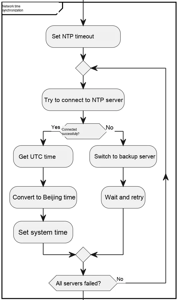
- Retry limit: A maximum of 5 retries (
max_retries= 5) to avoid infinite retries; - Server switching: After each failure, via
current_ntp_server =(current_ntp_server + 1) % len (ntp_servers)switch to the next NTP server (the 4 servers in the list are used in a loop); - Delayed retry: after each failure
time.sleep (2)—— to avoid server rate limiting caused by frequent requests in a short period of time.
max_retries = 5
retry_count = 0

while retry_count < max_retries:
    try:
        # Switch to the current NTP server
        ntptime.host = ntp_servers[current_ntp_server]
        print(f"Trying to sync time with {ntptime.host}...")
        ... ...

    except Exception as e:
        print(f'Failed to get time from {ntptime.host}: {e}')
        retry_count += 1

        # Switch to the next NTP server
        current_ntp_server = (current_ntp_server + 1) % len(ntp_servers)

        # Wait a while before retrying
        time.sleep(2)

# If all attempts fail, raise an exception
raise Exception("All NTP servers failed to respond after multiple attempts")
Next, proceed with NTP time acquisition and UTC to Beijing Time conversion by calling ntptime.settime ()— which retrieves the current NTP server's UTC time (Coordinated Universal Time) and automatically configures the MicroPython system clock;
# Get the time from the NTP server and set the system clock; note that it is UTC time
ntptime.settime()

# Get the current local time
nowtime = time.localtime()
Here, the time.localtime () method returns a time tuple in the following format:
(year, month, day, hour, minute, second, weekday, yearday)The specific meanings are shown in the following table:
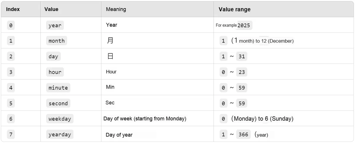
Here, Coordinated Universal Time (UTC) is 8 hours ahead of Beijing Time, which is commonly used in our daily lives. After obtaining the UTC time, we need to add 8 hours to get Beijing Time, and this is implemented via the convert_to_beijing_time () function in the code below:
# Convert UTC time to Beijing time (UTC+8)
def convert_to_beijing_time(utc_time: time.struct_time) -> time.struct_time:
    """
    Convert UTC time to Beijing time (UTC+8).

    Args:
        utc_time (time.struct_time): UTC time tuple.

    Returns:
        time.struct_time: Beijing time tuple.
    """
    # Convert the time tuple to a timestamp (seconds)
    utc_timestamp = time.mktime(utc_time)
    # Add 8 hours (8 * 3600 seconds)
    beijing_timestamp = utc_timestamp + 8 * 3600
    # Convert back to a time tuple
    return time.localtime(beijing_timestamp)
convert_to_beijing_time () function first uses the time.mktime () method to convert the time tuple (year, month, day, hour, minute, second, . ..) into a timestamp. A timestamp refers to the total number of seconds that have elapsed since midnight (UTC/GMT) on January 1,1970, namely 1970-01-01 00:00:00 UTC, after which the UTC time is added with 8 hours to be converted into Beijing time.
After that, use the time.localtime () method to convert the timestamp back to a time tuple in time.localtime () format, so as to convert UTC time to Beijing time.
In the main loop, we first obtain the RTC time, then in the rtc_to_localtime () function, we convert the RTC.datetime () time format to the time.localtime () time format:
# Convert RTC time to a format compatible with time.localtime()
def rtc_to_localtime(rtc_time: tuple) -> tuple:
    """
    Convert the 8-tuple returned by RTC.datetime() to an 8-tuple format compatible with time.localtime().

    Args:
        rtc_time (tuple): The 8-tuple returned by RTC.datetime() (year, month, day, weekday, hour, minute, second, subseconds).

    Returns:
        tuple: 8-tuple format (year, month, day, hour, minute, second, weekday, yearday).
    """
    # Ignore subseconds
    year, month, day, weekday, hour, minute, second, _ = rtc_time
    # Calculate the timestamp
    yearday = time.mktime((year, month, day, hour, minute, second, 0, 0, 0))
    # Get yearday (the day of the year)
    yearday = time.localtime(yearday)[7]

    return (year, month, day, hour, minute, second, weekday, yearday, -1)
In the API documentation of MicroPython, we can clearly see that RTC.datetime () and time.localtime () return different time and date data formats:
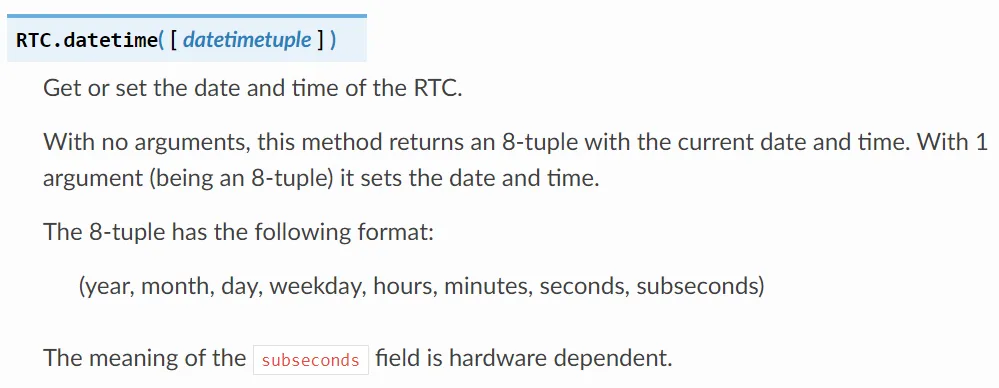
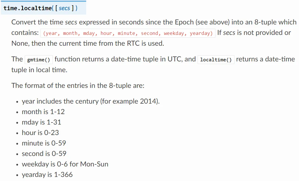
The comparison is shown in the table below:
Method Name | Element at index 0 | The 1st element | the 2nd element | the 3rd element | the 4th element | the 5th element | the 6th element | the 7th element |
| year | month | day | weekday | hours | minutes | seconds | subseconds |
| year | month | day | hours | minutes | seconds | weekday | yearday |
rtc_to_localtime () function mainly obtains the 8 values returned by RTC.datetime () through unpacking, converts its time tuple into a 9-tuple format, and then uses time.localtime () to convert the timestamp back into a time tuple in time.localtime () format.
After that, use the convert_to_beijing_time () function to get the Beijing time and print it to the terminal.
Burn the code and open the remote terminal:
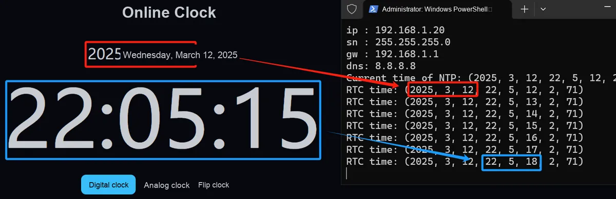
3.1 Application Experiment Result.mp4 3.7 MB
You can see the current time is output in a loop. Let's select an online web clock for comparison, and the URL of this online clock is:
https://onlinealarmkur.com/clock/zh-cn/
It can be seen that the RTC has a time difference of a few seconds from the online clock, which is a small error.
3.2 Implement a Simple Digital Alarm Clock Using the DS1302 RTC Clock
The following code can be found in the material package we provide, at the elegance-devkit v1\Demo\51 RTC_DS1302 folder.
3.2.1 Implementation of Custom DS1302 Class
In the following code, we use a custom DS1302 class to implement functions such as getting and setting time and date, as well as using the built-in RAM to store custom data. The sample code is as follows:
# Python env   : MicroPython v1.23.0
# -*- coding: utf-8 -*-
# @Time    : 2024/10/3 2:41 PM
# @Author  : Li Qingshui
# @File    : ds1302.py
# @Description : Custom DS1302 class to control the chip

# ======================================== Import Modules ========================================

# Import hardware-related modules
from machine import Pin
# Import MicroPython-related modules
from micropython import const

# ======================================== Global Variables ============================================

# ======================================== Functions ============================================

# ======================================== Custom Classes ============================================

# Custom DS1302 chip control class
class DS1302:
    """
    DS1302 class, used to operate the DS1302 real-time clock chip through a three-wire interface (CLK, DIO, CS).

    This class wraps communication with the DS1302 chip and provides functions such as reading and setting the time, date, and weekday.
    Supports starting and stopping the clock, as well as reading and writing the chip's internal RAM registers.

    Attributes:
        clk (Pin): Clock pin, used to generate the clock signal.
        dio (Pin): Data pin, used to read and write data.
        cs  (Pin): Chip select pin, used to enable chip communication.

    Methods:
        __init__(self, clk: Pin, dio: Pin, cs: Pin) -> None:
            Initialize the DS1302 class instance.

        _dec2hex(self, dat: int) -> int:
            Convert a decimal number to a hexadecimal number.

        _hex2dec(self, dat: int) -> int:
            Convert a hexadecimal number to a decimal number.

        _write_byte(self, dat: int) -> None:
            Write a byte to the DS1302.

        _read_byte(self) -> int:
            Read a byte from the DS1302.

        _get_reg(self, reg: int) -> int:
            Get the value of the specified register.

        _set_reg(self, reg: int, dat: int) -> None:
            Set the value of the specified register.

        _wr(self, reg: int, dat: int) -> None:
            Write data to a register and set write protection.

        start(self) -> None:
            Start the clock.

        stop(self) -> None:
            Stop the clock.

        second(self) -> int:
            Get the current seconds.

        second(self, value: int) -> None:
            Set the seconds.

        minute(self) -> int:
            Get the current minutes.

        minute(self, value: int) -> None:
            Set the minutes.

        hour(self) -> int:
            Get the current hours.

        hour(self, value: int) -> None:
            Set the hours.

        weekday(self) -> int:
            Get the current weekday.

        weekday(self, value: int) -> None:
            Set the weekday.

        day(self) -> int:
            Get the current date.

        day(self, value: int) -> None:
            Set the date.

        month(self) -> int:
            Get the current month.

        month(self, value: int) -> None:
            Set the month.

        year(self) -> int:
            Get the current year.

        year(self, value: int) -> None:
            Set the year.

        date_time(self, dat: list[int] | None = None) -> list[int] | None:
            Get or set the complete date and time.

        ram(self, reg: int, dat: int | None = None) -> int | None:
            Read or write the value of the RAM register.
    """
    # Class variables: define the DS1302 chip register addresses
    DS1302_REG_SECOND = const(0x80)  # Seconds register
    DS1302_REG_MINUTE = const(0x82)  # Minutes register
    DS1302_REG_HOUR = const(0x84)    # Hours register
    DS1302_REG_DAY = const(0x86)     # Date register
    DS1302_REG_MONTH = const(0x88)   # Month register
    DS1302_REG_WEEKDAY = const(0x8A) # Weekday register
    DS1302_REG_YEAR = const(0x8C)    # Year register
    DS1302_REG_WP = const(0x8E)      # Write-protect register
    DS1302_REG_CTRL = const(0x90)    # Control register
    DS1302_REG_RAM = const(0xC0)     # RAM register

    def __init__(self, clk: Pin, dio: Pin, cs: Pin) -> None:
        """
        Initialize the DS1302 class.

        Args:
            clk (Pin): Clock pin.
            dio (Pin): Data pin.
            cs  (Pin): Chip select pin.

        Returns:
            None
        """

        self.clk = clk
        self.dio = dio
        self.cs = cs

        # Initialize the clock pin as output
        self.clk.init(Pin.OUT)
        # Initialize the chip select pin as output
        self.cs.init(Pin.OUT)

    def _dec2hex(self, dat: int) -> int:
        """
        Convert decimal to hexadecimal.

        Args:
            dat (int): The decimal number to convert.

        Returns:
            int: The converted hexadecimal number.
        """
        return (dat // 10) * 16 + (dat % 10)

    def _hex2dec(self, dat: int) -> int:
        """
        Convert hexadecimal to decimal.

        Args:
            dat (int): The hexadecimal number to convert.

        Returns:
            int: The converted decimal number.
        """
        return (dat // 16) * 10 + (dat % 16)

    def _write_byte(self, dat: int) -> None:
        """
        Write a byte to the DS1302.

        Args:
            dat (int): The byte to write.

        Returns:
            None
        """
        # Set the data pin as output
        self.dio.init(Pin.OUT)

        # Write 8 bits of data
        for i in range(8):
            # Write each bit; data is written on the rising edge
            self.dio.value((dat >> i) & 1)
            # Generate the clock signal
            self.clk.value(1)
            self.clk.value(0)

    def _read_byte(self) -> int:
        """
        Read a byte from the DS1302.

        Returns:
            int: The byte that was read.
        """
        # Initialize temporary variable
        d = 0

        # Set the data pin as input
        self.dio.init(Pin.IN)

        # Read the eight bits of data in turn
        for i in range(8):
            # Read each bit; data is read on the falling edge
            d = d | (self.dio.value() << i)
            # Generate the clock signal
            self.clk.value(1)
            self.clk.value(0)
        return d

    def _get_reg(self, reg: int) -> int:
        """
        Get the value of the specified register.

        Args:
            reg (int): Register address.

        Returns:
            int: The value of the register.
        """
        # Start communication
        self.cs.value(1)
        # Write the register address
        self._write_byte(reg)
        # Read data
        t = self._read_byte()
        # End communication
        self.cs.value(0)
        return t

    def _set_reg(self, reg: int, dat: int) -> None:
        """
        Set the value of the specified register.

        Args:
            reg (int): Register address.
            dat (int): The data to write.

        Returns:
            None
        """
        # Start communication
        self.cs.value(1)
        # Write the register address
        self._write_byte(reg)
        # Write data
        self._write_byte(dat)
        # End communication
        self.cs.value(0)

    def _wr(self, reg: int, dat: int) -> None:
        """
        Write data to a register and set write protection.

        Args:
            reg (int): Register address.
            dat (int): The data to write.

        Returns:
            None
        """
        # Disable write protection
        self._set_reg(DS1302.DS1302_REG_WP, 0)
        # Write data
        self._set_reg(reg, dat)
        # Enable write protection
        self._set_reg(DS1302.DS1302_REG_WP, 0x80)

    def start(self) -> None:
        """
        Start the clock.
        Args:
            None

        Returns:
            None
        """
        # Read the seconds register
        t = self._get_reg(DS1302.DS1302_REG_SECOND + 1)
        # Clear the stop bit
        self._wr(DS1302.DS1302_REG_SECOND, t & 0x7f)

    def stop(self) -> None:
        """
        Stop the clock.
        Args:
            None

        Returns:
            None
        """
        # Read the seconds register
        t = self._get_reg(DS1302.DS1302_REG_SECOND + 1)
        # Set the stop bit
        self._wr(DS1302.DS1302_REG_SECOND, t | 0x80)

    @property
    def second(self) -> int:
        """
        Get the seconds.
        Args:
            None

        Returns:
            int: The current second.
        """
        return self._hex2dec(self._get_reg(DS1302.DS1302_REG_SECOND + 1)) % 60

    @second.setter
    def second(self, value: int) -> None:
        """
        Set the seconds.

        Args:
            value (int): The number of seconds to set.

        Returns:
            None
        """
        self._wr(DS1302.DS1302_REG_SECOND, self._dec2hex(value % 60))

    @property
    def minute(self) -> int:
        """
        Get the minutes.
        Args:
            None

        Returns:
            int: The current minutes.
        """
        return self._hex2dec(self._get_reg(DS1302.DS1302_REG_MINUTE + 1))

    @minute.setter
    def minute(self, value: int) -> None:
        """
        Set the minutes.

        Args:
            value (int): The number of minutes to set.

        Returns:
            None
        """
        self._wr(DS1302.DS1302_REG_MINUTE, self._dec2hex(value % 60))

    @property
    def hour(self) -> int:
        """
        Get the hours.
        Args:
            None

        Returns:
            int: The current hours.
        """
        return self._hex2dec(self._get_reg(DS1302.DS1302_REG_HOUR + 1))

    @hour.setter
    def hour(self, value: int) -> None:
        """
        Set the hours.

        Args:
            value (int): The number of hours to set.

        Returns:
            None
        """
        self._wr(DS1302.DS1302_REG_HOUR, self._dec2hex(value % 24))

    @property
    def weekday(self) -> int:
        """
        Get the day of the week.
        Args:
            None

        Returns:
            int: The current day of the week.
        """
        return self._hex2dec(self._get_reg(DS1302.DS1302_REG_WEEKDAY + 1))

    @weekday.setter
    def weekday(self, value: int) -> None:
        """
        Set the day of the week.

        Args:
            value (int): The day of the week to set.

        Returns:
            None
        """
        self._wr(DS1302.DS1302_REG_WEEKDAY, self._dec2hex(value % 8))

    @property
    def day(self) -> int:
        """
        Get the day.
        Args:
            None

        Returns:
            int: The current day.
        """
        return self._hex2dec(self._get_reg(DS1302.DS1302_REG_DAY + 1))

    @day.setter
    def day(self, value: int) -> None:
        """
        Set the day.

        Args:
            value (int): The day to set.

        Returns:
            None
        """
        self._wr(DS1302.DS1302_REG_DAY, self._dec2hex(value % 32))

    @property
    def month(self) -> int:
        """
        Get the month.
        Args:
            None

        Returns:
            int: The current month.
        """
        return self._hex2dec(self._get_reg(DS1302.DS1302_REG_MONTH + 1))

    @month.setter
    def month(self, value: int) -> None:
        """
        Set the month.

        Args:
            value (int): The month to set.

        Returns:
            None
        """
        self._wr(DS1302.DS1302_REG_MONTH, self._dec2hex(value % 13))

    @property
    def year(self) -> int:
        """
        Get the year.
        Args:
            None

        Returns:
            int: The current year.
        """
        return self._hex2dec(self._get_reg(DS1302.DS1302_REG_YEAR + 1)) + 2000

    @year.setter
    def year(self, value: int) -> None:
        """
        Set the year.

        Args:
            value (int): The year to set.

        Returns:
            None
        """
        self._wr(DS1302.DS1302_REG_YEAR, self._dec2hex(value % 100))

    def date_time(self, dat: list[int] | None = None) -> list[int] | None:
        """
        Get or set the date and time.

        Args:
            dat (list[int] | None): Date and time data [year, month, day, weekday, hour, minute, second]. If None, get the current time.

        Returns:
            list[int] | None: If dat is None, returns [year, month, day, weekday, hour, minute, second]; otherwise returns None.
        """
        if dat is None:
            return [self.year, self.month, self.day, self.weekday, self.hour, self.minute, self.second]
        else:
            self.year = dat[0]
            self.month = dat[1]
            self.day = dat[2]
            self.weekday = dat[3]
            self.hour = dat[4]
            self.minute = dat[5]
            self.second = dat[6]

    def ram(self, reg: int, dat: int | None = None) -> int | None:
        """
        Read or write the RAM register.

        Args:
            reg (int): Register address.
            dat (int | None): The data to write. If None, read the data.

        Returns:
            int | None: If dat is None, returns the data read; otherwise returns None.
        """
        if dat is None:
            return self._get_reg(DS1302.DS1302_REG_RAM + 1 + (reg % 31) * 2)
        else:
            self._wr(DS1302.DS1302_REG_RAM + (reg % 31) * 2, dat)

# ======================================== Initialization ==========================================

# ========================================  Main Program  ============================================
First, we define a series of constants, which represent DS1302 the register addresses of the chip:
# Custom DS1302 chip control class
class DS1302:

    # Class variables: define the DS1302 chip register addresses
    DS1302_REG_SECOND = const(0x80)  # Seconds register
    DS1302_REG_MINUTE = const(0x82)  # Minutes register
    DS1302_REG_HOUR = const(0x84)    # Hours register
    DS1302_REG_DAY = const(0x86)     # Date register
    DS1302_REG_MONTH = const(0x88)   # Month register
    DS1302_REG_WEEKDAY = const(0x8A) # Weekday register
    DS1302_REG_YEAR = const(0x8C)    # Year register
    DS1302_REG_WP = const(0x8E)      # Write-protect register
    DS1302_REG_CTRL = const(0x90)    # Control register
    DS1302_REG_RAM = const(0xC0)     # RAM register
Set the clock pin (clk), data pin (dio) and chip select pin (cs) in the initialization method.
The underlying method for implementing DS1302 operations is as follows:
- Single-byte Write
_write_byteMethod: First, set the DIO pin to output mode, write each bit of data sequentially through a loop, and generate a clock pulse (high level followed by low level) when transmitting each bit of data. - Single-byte Read
_read_byteMethod: Set the DIO pin to input mode, read each bit of data sequentially through a loop, and return the complete byte that has been read.
The methods related to register read and write are implemented by calling _write_byte () and _read_byte () methods: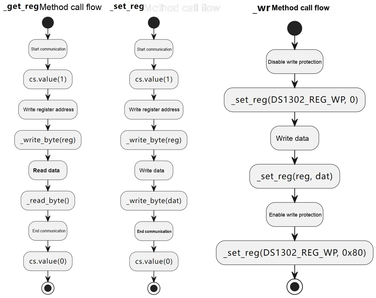
- Register Value Acquisition
_get_regMethod: First, set the CS pin to high, write the target register address and read the data returned by the DS1302 chip, then set the CS pin to low to terminate the communication session. - Register Value Write
_set_regMethod: First, set the CS pin to high, write the target register address and the data to be written, then set the CS pin to low to terminate the communication session. - WP Register Write
_wrMethod: This method writes data to the WP write protection register: first, set the write protection registerWPto0to disable write protection, then write data to the target register, and finally set the write protection register WP to0x80to enable write protection
These methods encapsulate low-level register read and write operations, and control the DS1302 chip can be achieved by calling these methods in other methods, for example:
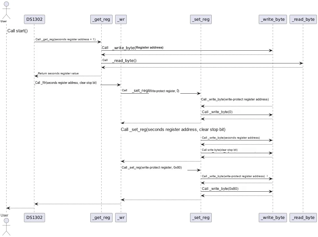
- Start the clock
startMethod: First read the current value of the second register, then clear the highest bit (STOPbit) to enableDS1302to start timing. The calling relationship is shown in the following figure:
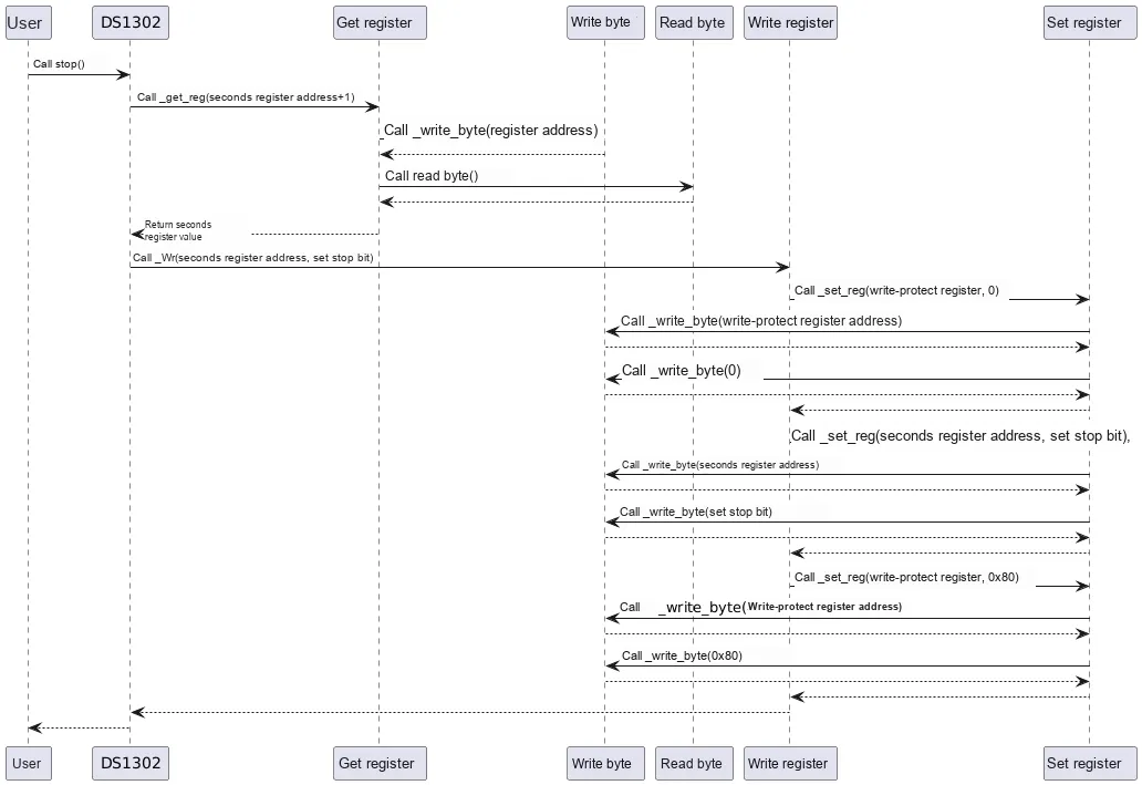
- Stop the clock
stopmethod: First read the current value of the seconds register, then set the highest bit (theSTOPbit) to stop the timing of theDS1302, and the calling relationship is shown in the following figure:
In the methods for getting and setting time data, including the second, minute, hour, weekday, day, month, and year methods, the operations are mainly implemented by reading and writing the corresponding registers:
@property
def second(self) -> int:
    """
    Get the seconds.
    Args:
        None

    Returns:
        int: The current second.
    """
    return self._hex2dec(self._get_reg(DS1302.DS1302_REG_SECOND + 1)) % 60

@second.setter
def second(self, value: int) -> None:
    """
    Set the seconds.

    Args:
        value (int): The number of seconds to set.

    Returns:
        None
    """
self._wr(DS1302.DS1302_REG_SECOND, self._dec2hex(value % 60))- Read Time: Read the value of the corresponding register via the
_get_regmethod, and use_hex2decto convert the hexadecimal data into decimal time data; - Write Time: Convert the decimal data to hexadecimal via the
_wrmethod and write it to the corresponding register to set the time.
Furthermore, by using Python's @property decorator, we also implemented getter and setter methods for each time and date component (seconds, minutes, hours, day of week, date, month, year) of the DS1302. We encapsulated the internal class data (such as the register values of DS1302) to prevent external code from directly accessing and modifying these internal data; meanwhile, external code can call these methods in the form of attribute access, making the code more intuitive and readable, just like accessing ordinary object attributes rather than explicitly invoking methods.
For user convenience, we also provide a date_time method for getting or setting the full date and time: if no parameter is passed, it returns a list of the current complete date and time[year, month, day, weekday, hour, minute, second]; conversely, if a list containing date and time values is passed, it will sequentially configure each time component of the DS1302:
def date_time(self, dat: list[int] | None = None) -> list[int] | None:
    """
    Get or set the date and time.

    Args:
        dat (list[int] | None): Date and time data [year, month, day, weekday, hour, minute, second]. If None, get the current time.

    Returns:
        list[int] | None: If dat is None, returns [year, month, day, weekday, hour, minute, second]; otherwise returns None.
    """
    if dat is None:
        return [self.year, self.month, self.day, self.weekday, self.hour, self.minute, self.second]
    else:
        self.year = dat[0]
        self.month = dat[1]
        self.day = dat[2]
        self.weekday = dat[3]
        self.hour = dat[4]
        self.minute = dat[5]
        self.second = dat[6]
In the access to the internal RAM of the DS1302 chip, we provide the RAM register read and write ram method:
- Read
RAM: If nodatparameter is passed, read the data at the specifiedRAMaddress - Write to
RAM: If thedatparameter is passed in, write data to the specifiedRAMaddress
def ram(self, reg: int, dat: int | None = None) -> int | None:
    """
    Read or write the RAM register.

    Args:
        reg (int): Register address.
        dat (int | None): The data to write. If None, read the data.

    Returns:
        int | None: If dat is None, returns the data read; otherwise returns None.
    """
    if dat is None:
        return self._get_reg(DS1302.DS1302_REG_RAM + 1 + (reg % 31) * 2)
    else:
        self._wr(DS1302.DS1302_REG_RAM + (reg % 31) * 2, dat)
Here, the internal RAM has a starting write address of 0xC0 and a starting read address of 0xC1, where (reg % 31) * 2 ensures that the register index falls within the range of 0 to 30 and calculates the address offset based on the register index.
3.2.2 Experimental Phenomena
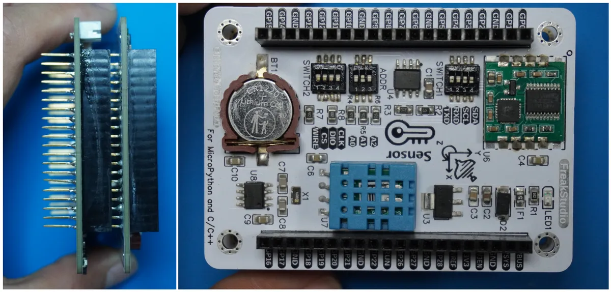
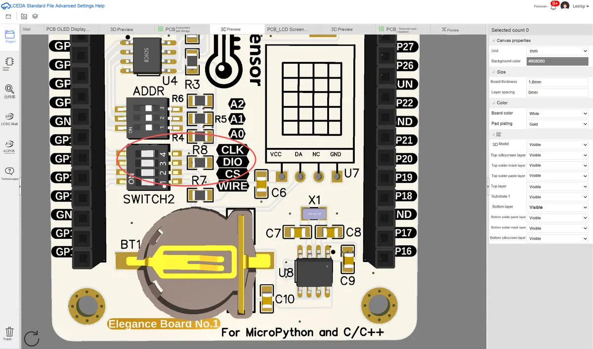
In the following experiment, we need to insert Fengya No. 1 Board - Environment and Storage Acquisition Board into Fengya No. 1 Board - Universal Compatible Expansion Board, and turn on the Fengya No. 1 Board - Environment and Storage Acquisition Board 's SWITCH2 DIP switch' s CLK, DIO and CS options:
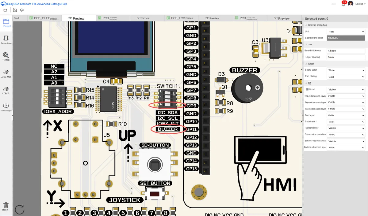
Then insert the Fengya No. 1 Board - Universal Compatible Expansion Board into the Fengya No. 1 Board - OLED Display and Interaction Expansion Board, and at the same time turn on the Fengya No. 1 Board - OLED Display and Interaction Expansion Board 's SWITCH1 dip switch' s I2C_SDA, I2C_SCL and BUZZER options:
In addition, please select an address on the OLED_ADDR DIP switch. This example sets the switch to 0x3C, so the OLED screen's I²C address is 0x3C:
Here, the connection between each module and the Raspberry Pi Pico is shown as follows:
| Component | Pin name | Pin connected to Raspberry Pi Pico |
|---|---|---|
| DS1302 | CLK | GPIO10 |
| DS1302 | DIO | GPIO11 |
| DS1302 | CS/CE | GPIO12 |
| SSD1306 OLED | SDA | GPIO6 |
| SSD1306 OLED | SCL | GPIO7 |
| Buzzer | DOUT | GPIO9 |
In the following code, we use a custom DS1302 class to implement a clock system with alarm function via the DS1302 real-time clock module and the SSD1306 OLED display. This system can display the current date and time, and trigger a buzzer alert when the preset alarm time is reached.
The sample code is as follows:
# Python env   : MicroPython v1.23.0
# -*- coding: utf-8 -*-
# @Time    : 2024/10/3 2:41 PM
# @Author  : Li Qingshui
# @File    : main.py
# @Description : External RTC experiment, implementing an alarm clock with the DS1302

# ======================================== Import Modules ========================================

# Import hardware-related modules
from machine import Pin, I2C, Timer, PWM, RTC
# Import time-related modules
import time
# Import the external RTC real-time clock module
from ds1302 import DS1302
# Import the SSD1306_I2C class from the SSD1306 module
from SSD1306 import SSD1306_I2C

# ======================================== Global Variables ============================================

# OLED screen address
OLED_ADDRESS = 0

# ======================================== Functions ============================================

def display_time(timer: Timer) -> None:
    """
    Timer callback function, used to display the current time on the OLED screen.

    This function is called periodically by a timer. It gets the current time from the DS1302 real-time clock chip,
    and displays the date and time centered on the OLED screen. It also checks whether the current time matches a set alarm,
    and if it matches, triggers the alarm; otherwise, stops the alarm buzzer.

    Args:
        timer (Timer): Timer object, used to call this function periodically.

    Returns:
        None
    """
    # Declare global variables
    global ds1302, oled, alarm_clock

    # Get the current time
    current_time = ds1302.date_time()

    # Clear the title area
    oled.fill_rect(0, 0, 128, 16, 0)

    # Display the title
    title = "RTC Clock"
    title_width = len(title) * 8
    title_x = (128 - title_width) // 2
    oled.text(title, title_x, 0)

    # Format the date string
    date_str = "{:04}-{:02}-{:02}".format(current_time[0], current_time[1], current_time[2])
    # Calculate the position to center the date
    date_width = len(date_str) * 8
    date_x = (128 - date_width) // 2

    # Format the time string
    time_str = "{:02}:{:02}:{:02}".format(current_time[4], current_time[5], current_time[6])
    # Calculate the position to center the time
    time_width = len(time_str) * 8
    time_x = (128 - time_width) // 2

    # Clear the date and time area
    oled.fill_rect(0, 16, 128, 32, 0)

    # Display the date and time
    oled.text(date_str, date_x, 16)
    oled.text(time_str, time_x, 32)

    # Check the alarm
    if alarm_clock.check_alarms(current_time):
        # Stop the timer
        timer.deinit()
        # Reinitialize the timer
        timer.init(period=100, mode=Timer.PERIODIC, callback=display_time)
    else:
        # Stop the alarm buzzer
        alarm_clock.stop_alarm()
        # Refresh the screen
        oled.show()

# ======================================== Custom Classes ============================================

# Custom alarm clock class
class AlarmClock:
    """
    AlarmClock class, used to manage alarm functions, supporting setting, deleting and triggering alarms.

    This class displays the alarm status on the OLED display and sounds the alarm tone through the buzzer.
    Supports setting multiple alarms and triggering them at the specified times.

    Attributes:
        oled (SSD1306_I2C): OLED instance, used to display the alarm status.
        buzzer (PWM): Buzzer control pin, used to sound the alarm tone.
        alarms (list): List storing the alarm times, in the format [(hour, minute), ...].

    Methods:
        __init__(self, oled: SSD1306_I2C, buzzer_pin: Pin) -> None:
            Initialize the AlarmClock class instance.

        set_alarm(self, hours: int, minutes: int) -> None:
            Set an alarm.

        delete_alarm(self, hours: int, minutes: int) -> None:
            Delete the specified alarm.

        check_alarms(self, current_time: tuple[int, int, int]) -> None:
            Check whether the current time matches a set alarm time.

        trigger_alarm(self) -> None:
            Trigger the alarm and turn on the buzzer.

        stop_alarm(self) -> None:
            Stop the alarm and turn off the buzzer.
    """
    def __init__(self, oled: SSD1306_I2C, buzzer_pin: Pin) -> None:
        """
        Initialize the alarm clock class.

        Args:
            oled (SSD1306_I2C): OLED instance, used to display the alarm status.
            buzzer_pin (Pin): Buzzer control pin.
        """
        # Save the OLED instance
        self.oled = oled
        # Initialize the buzzer pin as PWM output with a duty cycle of 0
        self.buzzer = PWM(buzzer_pin, freq=1000, duty_u16=0)
        # List storing the alarm times
        self.alarms = []

    def set_alarm(self, hours: int, minutes: int) -> None:
        """
        Set an alarm.

        Args:
            hours (int): Hours, in the range 0-23.
            minutes (int): Minutes, in the range 0-59.

        Returns:
            None

        Raises:
            ValueError: If the hours or minutes are not within the valid range.
        """
        # Verify that the hours and minutes are within the valid range
        if (hours < 0 or hours > 23) or (minutes < 0 or minutes > 59):
            # Raise an exception
            raise ValueError("Invalid time for alarm")
            # Add the alarm time to the list
        self.alarms.append((hours, minutes))

    def delete_alarm(self, hours: int, minutes: int) -> None:
        """
        Delete the specified alarm.

        Args:
            hours (int): Hours.
            minutes (int): Minutes.

        Returns:
            None
        """
        try:
            # Delete the specified alarm from the list
            self.alarms.remove((hours, minutes))
        except ValueError:
            # If the alarm is not found, print a message
            print("Alarm not found")

    def check_alarms(self, current_time: tuple[int, int, int]) -> None:
        """
        Check whether the current time matches a set alarm time.

        Args:
            current_time (tuple[int, int, int]): Tuple of the current time (hours, minutes, seconds).

        Returns:
            None
        """
        # Get the current hours and minutes
        current_hours, current_minutes = current_time[4], current_time[5]
        # Iterate over all set alarms
        for alarm in self.alarms:
            # If the alarm time is reached
            if alarm[0] == current_hours and alarm[1] == current_minutes:
                # Trigger the alarm
                self.trigger_alarm()
                # Clear the screen
                self.oled.fill(0)
                # Display the "Alarm!" prompt on the screen
                self.oled.text("Alarm!", 0, 0)
                # Refresh the screen
                self.oled.show()

    def trigger_alarm(self) -> None:
        """
        Trigger the alarm and turn on the buzzer.

        Args:
            None

        Returns:
            None
        """
        # Turn on the buzzer
        self.buzzer.duty_u16(32000)

    def stop_alarm(self) -> None:
        """
        Stop the alarm and turn off the buzzer.

        Returns:
            None
        """
        # Turn off the buzzer
        self.buzzer.duty_u16(0)

# ======================================== Initialization ==========================================

# Power-on delay of 3 s
time.sleep(3)
# Print debug message
print("FreakStudio: Implement an alarm clock using DS1302")

# Create the DS1302 object
ds1302 = DS1302(clk=Pin(10), dio=Pin(11), cs=Pin(12))

# Before flashing the program, be sure to use the mpremote rtc --set command to set the built-in RTC real-time clock to the host computer's time
# Then open the REPL and enter the following commands:
#   from machine import Pin,  RTC
#   from ds1302 import DS1302
#   rtc = RTC()
#   year, month, day, weekday, hour, minute, second, _ = rtc.datetime()
#   ds1302 = DS1302(clk=Pin(10), dio=Pin(11), cs=Pin(12))
#   ds1302.date_time([year, month, day, weekday, hour, minute, second])
# Then exit REPL mode and restart the device: mpremote reset

# Create a hardware I2C instance using the I2C1 peripheral, clock frequency 400KHz, SDA pin 6, SCL pin 7
i2c = I2C(id=1, sda=Pin(6), scl=Pin(7), freq=400000)

# Start scanning for devices on the I2C bus and return a list of slave addresses
devices_list = i2c.scan()
print('START I2C SCANNER')

# If devices_list is empty, no device is connected to the I2C bus
if len(devices_list) == 0:
    print("No i2c device !")
# If not empty, print the slave device addresses
else:
    print('i2c devices found:', len(devices_list))
    # Iterate over the slave device address list
    for device in devices_list:
        # Check whether the slave device address is 0x3c or 0x3d (i.e., the address of the OLED SSD1306)
        if device == 0x3c or device == 0x3d:
            print("I2C hexadecimal address: ", hex(device))
            OLED_ADDRESS = device

# Create an SSD1306 OLED screen instance, width 128 pixels, height 64 pixels, without external power supply
oled = SSD1306_I2C(i2c, OLED_ADDRESS, 128, 64,False)

# Create an alarm clock instance
alarm_clock = AlarmClock(oled, buzzer_pin=Pin(9))
# Alarm setting example
alarm_clock.set_alarm(18, 3)

# Create a software timer instance
timer = Timer(-1)
# Call the display_time function every 100 ms to update the display
timer.init(period=100, mode=Timer.PERIODIC, callback=display_time)

# ========================================  Main Program  ============================================

# Loop forever, checking whether the alarm time has been reached
while True:
    # Get the current time
    current_time = ds1302.date_time()
    # Delay 1s
    time.sleep(1)
    # Print the current time
    print("Current Time: {:02}:{:02}:{:02}".format( current_time[4], current_time[5], current_time[6]))
Here, we manage the functions of setting, deleting and triggering alarms in the custom AlarmClock class. When the current time reaches the set time of any alarm, the buzzer will be triggered and a prompt message will be displayed on the OLED. The meaning of each method is as follows: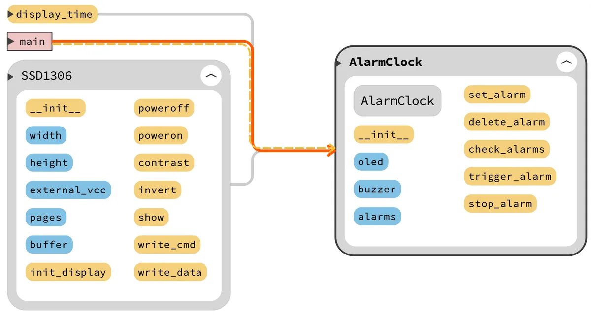
- Class Initialization
initMethod: First, save the OLED instance and initialize the buzzer, then initialize the alarm listself.alarms = []for storing multiple alarm times. - Set Alarm
set_alarmMethod: Adds an alarm time to the alarm list by specifying the hour and minute. First, perform parameter validation to ensure thathoursis within the range of0-23andminutesis within the range of0-59, then add the(hours, minutes)tuple to the alarm list. - Delete Alarm
delete_alarmMethod: Remove the corresponding alarm time from the alarm list based on the provided hour and minute; if the specified alarm time does not exist in the list, catch theValueErrorexception and print a prompt message. - Check alarms
check_alarmsMethod: Compare whether the hour and minute of the current time match each alarm time in the alarm list; if there is a match, trigger the alarm, display a prompt message on the OLED screen, turn on the buzzer, and returnTrue; if none of the alarms match, returnFalse.
Then, we create an instance of the DS1302 class and AlarmClock class instance, then initialize a software timer, set its timing period to 100 milliseconds, and call the display_time function in periodic mode. In the display_time function, the current time will be obtained from ds1302, the title (" RTC Clock "), date and time on the OLED screen will be updated, and alarm_clock.check_alarms will be called to check whether the alarm is triggered:
- If the current time matches a set alarm time, the alarm will be triggered (the buzzer will be activated), and at the same time, it will be displayed on the
OLEDscreen as "Alarm!"; - If there is no match, the buzzer will be stopped (
PWMduty cycle set to 0).
While in the main loop, the current time is obtained every second via ds1302.date_time (), and then printed to the terminal in the format of " HH: mm: ss ".
The overall time sequence process is shown in the following figure:
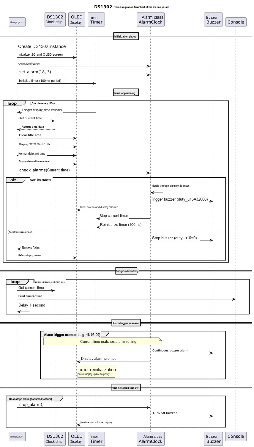
It should be noted that before burning the code, we still need to complete one more task, which is to synchronize the external RTC (Real-Time Clock) with the time of the computer.
First, use the mpremote rtc --set command to synchronize the built-in RTC time of the Raspberry Pi Pico with the time of the host computer:
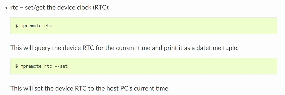
If the built-in RTC is not synchronized in advance, the built-in RTC of the Pico will lose the time after power off (it has no backup battery, and the time will be reset to the initial value after power off, for example 2021-01-01 00:00:00). At this time, the built-in RTC time read by the code is incorrect. After writing to DS1302, the time of the entire alarm clock system will start to run from the wrong initial value (for example, displaying "2021"), resulting in the complete failure of the alarm clock function.
Next, you also need to open REPL and enter the following commands in sequence to synchronize the time of the built-in RTC to the external DS1302 real-time clock:
from machine import Pin, RTC
from ds1302 import DS1302
rtc = RTC()
year, month, day, weekday, hour, minute, second, _ = rtc.datetime()
ds1302 = DS1302(clk=Pin(10), dio=Pin(11), cs=Pin(12))
ds1302.date_time([year, month, day, weekday, hour, minute, second])
3.2.1 Time Configuration.mp4 1017 KB
After the above commands finish executing, we exit the REPL mode, and finally restart the device via the mpremote reset command to ensure that the time configuration takes full effect.
When flashing the code, the following content is displayed in the terminal:
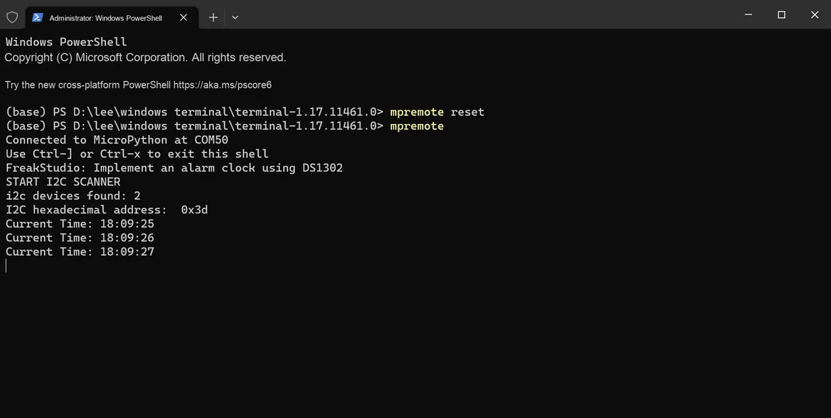
It can be seen that the terminal keeps updating the current time, and the OLED screen behaves in exactly the same way:
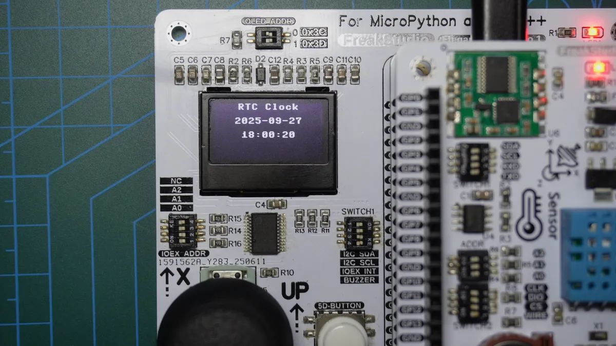
When the set time of the alarm clock is reached, the buzzer emits intermittent sounds, and a prompt message is displayed on the OLED screen at the same time:
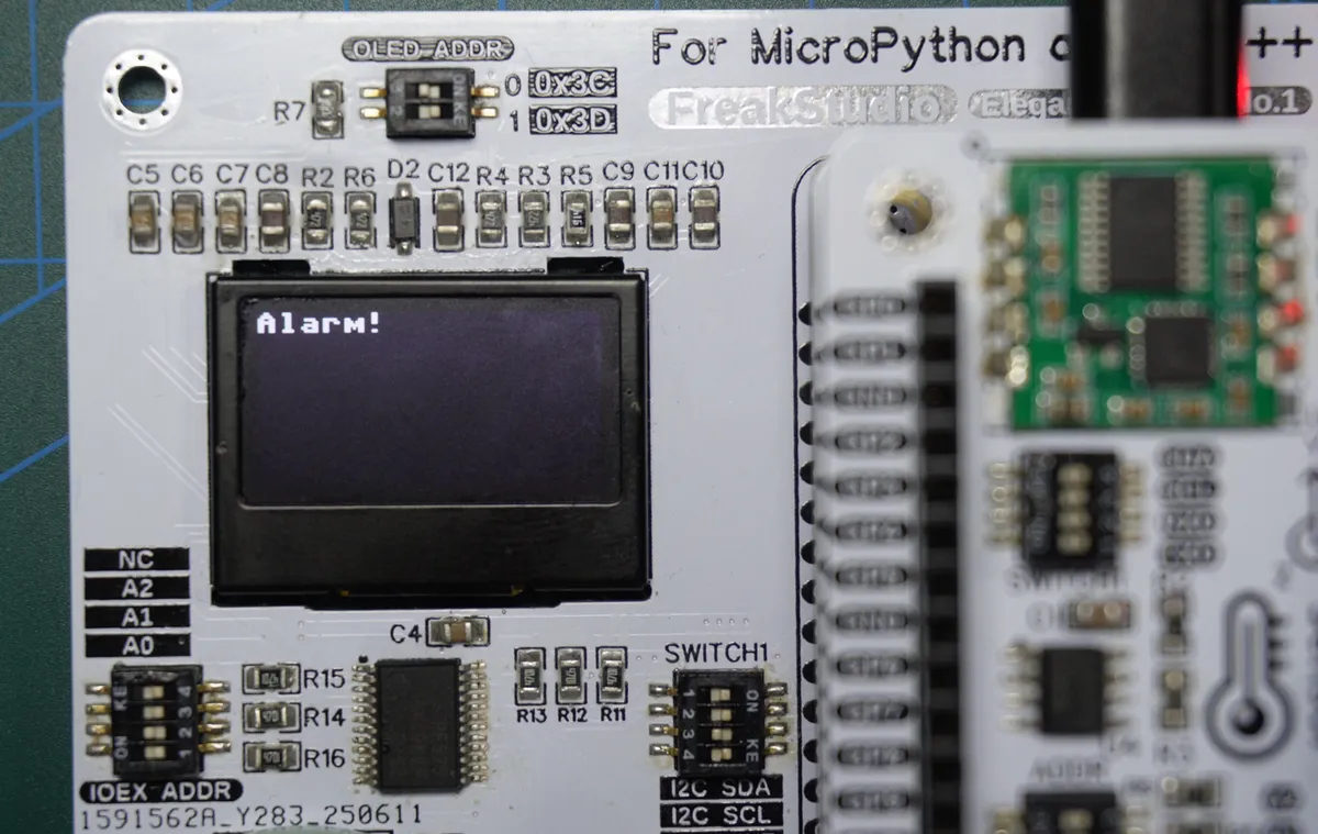
3.2.2 Application Experiment Result.mp4 27.5 MB
References
- Real Time Clocks (RTCs) in Microcontroller Timers
https://www.allaboutcircuits.com/technical-articles/introduction-to-microcontroller-timers-real-time-clocks/
- Real-time clock
https://en.wikipedia.org/wiki/Real-time_clock
- RP2040 (Raspberry Pi Pico) Clock System
https://www.taterli.com/7517
- RP2040 (Raspberry Pi Pico) General-purpose Timer & RTC
https://www.taterli.com/7561
- DS1302 N/Z Serial Real-Time Clock IC
- DS1302 Trickle-Charge Timekeeping Chip
Version Record
Version Number | Modifier | Time | Content |
v1.0.0 | Li Zisheng | 2025/09/18 | Initialize the document, based on MicroPython version V1.23.0. |