
Contents
- 1. Hardware Explanation
- 1.1 Timer
- 1.2 Basic Structure and Concepts of Timers
- 1.3 Overview of Timers on Raspberry Pi Pico
- 2. Software Control Method
- 2.1 Constructor of the machine.Timer class
- 2.2 Other Methods of the machine.Timer Class
- 2.3 Constructor method of the machine.PWM class
- 2.4 Other methods of the machine.PWM class
- 3. Application Examples
- 3.1 Key Detection Finite-State Machine Framework Implemented by Timer
- 3.2 Implementing Task Scheduler with Timer
- 3.3 Timer Reads the Status of the Rotary Encoder
- 3.5 PWM Signal Control for LED Breathing Light
- 3.6 PWM Signal Control of RGB LED
- 3.7 PWM Signal Driven Buzzer
- References
- Version Record
1. Hardware Explanation
1.1 Timer
1.1.1 Introduction to Timers
Imagine a scenario where we need to send data via the UART peripheral every 1 second, sample external signals at equal intervals 100 times within 1 second using the ADC analog-to-digital converter, delay for 10ms between executing two function functions, or obtain the current date and time. All these tasks that require tracking the passage of time and performing corresponding operations at set time points necessitate the use of the timer peripheral in the MCU.
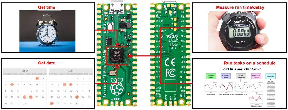
You might say, "I can achieve the timing effect just through the following steps without using a timer". For example: assuming that the CPU takes 1 microsecond to execute the instructions inside the loop, we can set up a while loop, define a timing variable with an initial value of 0, and perform the following operations within the loop:
- The timing variable increments;
- Determine whether the timing variable reaches a preset time point;
- If reached, execute the corresponding operation.
The main problem with this method is that it occupies all CPU resources to detect whether the preset time point is reached, making it impossible to perform other operations. Meanwhile, it is not flexible enough; for example, we may need to set multiple scheduled times to execute different operations or require custom time increments.
Simply put, a timer is a counter designed for scheduled event processing: it increments or decrements at fixed intervals, and when it reaches the preset count value, it triggers a timer interrupt to execute the user's predefined operation. Common timers can be categorized into the following types:
- General-purpose timer: This is the most flexible type of timer, which can be used both to measure the frequency/duration of external signals (e. g., detecting how long a key is pressed) and to schedule periodic tasks (e. g., reading sensor data once every second);
- PWM Timer: A timer specifically designed to generate PWM (Pulse Width Modulation) signals, which can be used to control the power or position of a device; the most typical application scenario is the angle control of servo motors and steering gears.
- Systick System Tick Timer: It is a built-in timer of the CPU core, serving as the "basic time reference" of the system to generate periodic interrupts, and acts as the core dependency for operating system task scheduling and system delay functions.
- RTC Real-Time Clock: A timer specifically designed to record "real time/date". Different from other timers that only handle "interval timing", it allows direct setting and reading of year/month/day/hour/minute/second, and can be applied in scenarios such as time logging, event timestamping, and alarm reminders.
- WDT Watchdog Timer: A specialized timer for system fault recovery, which continuously monitors the operating status of the CPU. If the CPU stops responding due to program runaway, the watchdog timer will trigger a system reset to help the system resume normal operation.
Here, the functions and applications of the RTC (Real-Time Clock) and WDT (Watchdog Timer) are relatively special compared with other timers, which will be covered in the subsequent chapters.
1.1.2 Working Principle of Timer
Here, we summarize the common features of different timers and explain their working principles.
1.1.2.1 Basic Composition of the Timer
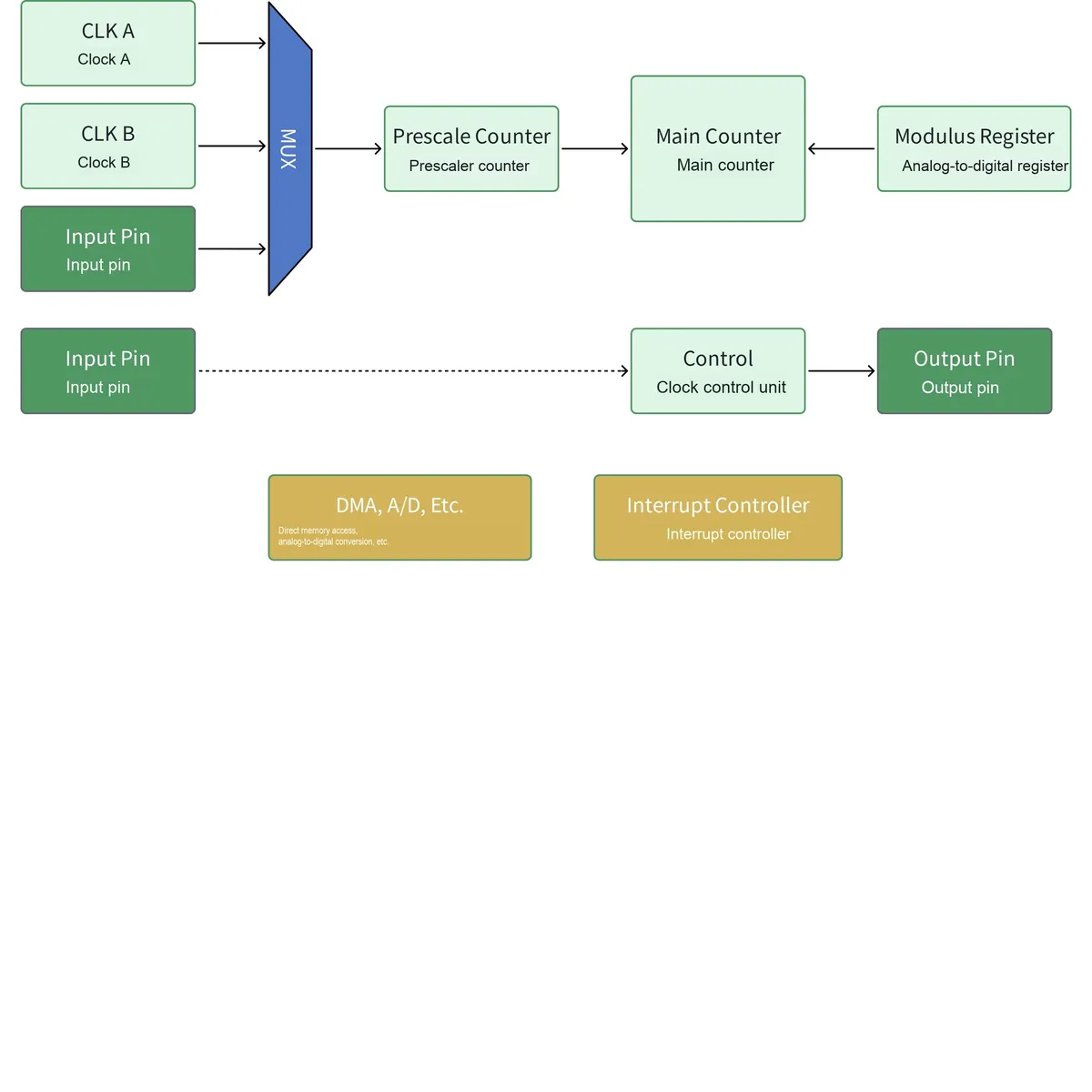
Simply put, timers can be divided into the following parts:
- Clock Input Unit: Each timer requires a clock source or time base. There are typically multiple possible clock sources, such as internal clocks and external signals, from which one can be selected via a switch or a multiplexer;
- Prescaler: To expand the counting range of the counter (the maximum count value of a counter has an upper limit; each pulse input to the clock increments the counter's count by one unit, and when the input clock frequency decreases, the maximum counting duration of the counter increases accordingly), the selected clock feeds into the "prescaler", which is primarily used to adjust the clock rate. The division factor of a prescaler is typically restricted to a power of 2. For instance, 2⁰ to 2⁷ provide options of 1,2, 4,8, 16,32,64 or 128. Some prescalers support up to 2¹⁶, i. e. 65536;
- Counter: A register used to count clock pulses;
- Clock Control Unit: it can be used to configure the working mode of the timer (such as whether to count up or count down, whether to count on the rising edge or the falling edge of the input clock, etc.), start-stop control, interrupt enable and other operations;
- Related registers: mainly include comparison registers and count registers:
- Count register: stores the current count value
- Compare Register: stores the value to be compared with the count register; when the value of the counter reaches the value of the compare register, a corresponding event is triggered.
- Trigger Input Unit: Simply put, it refers to the signal introduced externally to this timer. The timer can perform edge capture on the external input signal to generate a capture event, and can trigger an interrupt or DMA request while recording the value of the counter at the capture moment. Based on this principle, combined with the real-time counting function of the counter, the pulse width of the captured signal can be measured, so as to realize the measurement of the period or duty cycle of periodic waveforms, or be used for communication decoding.
- Trigger Output Unit: When the value of the counter reaches the value of the comparison register, a trigger signal is output to other timers or peripherals.
- Connection Interrupt and DMA: When the timer count reaches the preset value, it can trigger an interrupt or DMA. A common application scenario is ADC timed sampling: we configure the timer's timing period and the ADC's DMA. When the timer reaches the set time, it triggers the DMA, which transfers the data collected by the ADC peripheral from the registers to the memory unit.
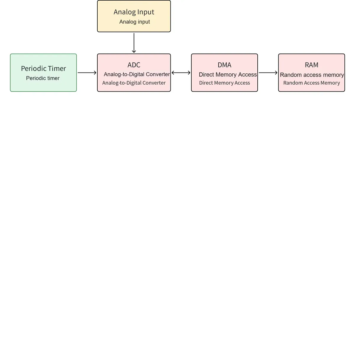
Common interrupt events include:
- Counter Overflow Interrupt: Triggered when the counter returns to zero from its maximum value
- Compare Match Interrupt: Triggered when the counter value equals the value of the compare register
1.1.2.2 Operating Modes of the Timer
Several common operating modes of timers include timing mode, counting mode, and PWM mode.
1.1.2.2.1 Timing Mode
First, it is necessary to clarify that the main program and the timer task are executed asynchronously, and the execution flow of the timer task is independent of the main program flow.
The so-called periodic timer mode means that the timer generates an interrupt after a set time interval, which is often used for the execution of periodic tasks.
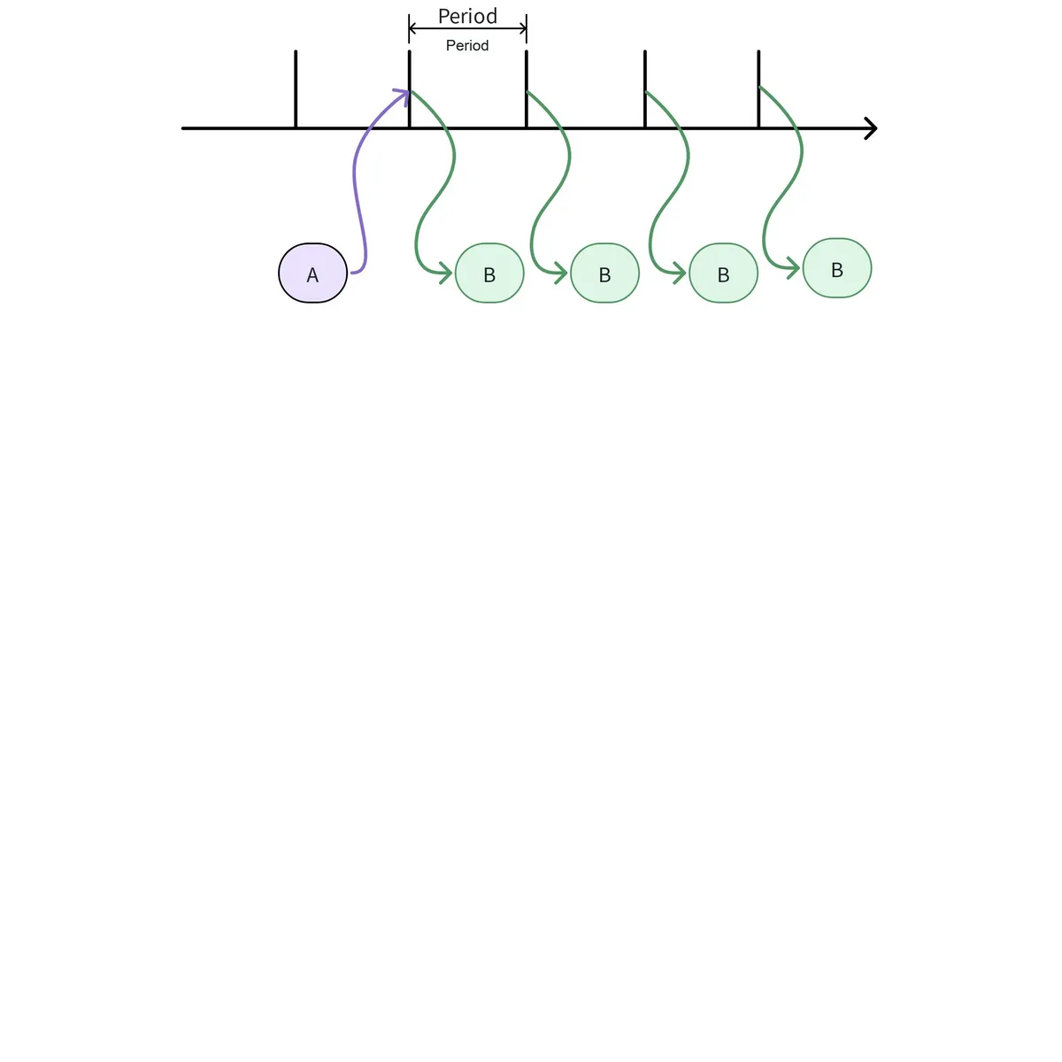
The timer mode is commonly used in the following scenarios:
- Scheduled Data Acquisition: Timer-triggered DMA transmits the sensor data collected in the ADC registers to the memory
- Task Scheduling: In a multitasking system, timers are used to schedule the execution of tasks and ensure that each task is performed within the specified time interval.
- Input signal detection: Detect whether there is signal input from keys, sensors, etc.
1.1.2.2.2 Counting Mode
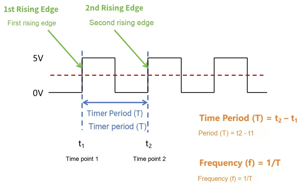
In counter mode, the timer can be used to count the occurrences of external events, such as pulse counting, step counting of stepper motors, etc.
1.1.2.2.3 PWM Mode
In PWM mode, the timer can generate PWM signals with a specific frequency and duty cycle to control electronic devices, such as adjusting the brightness of LEDs and controlling the position of servo motors.
PWM signal
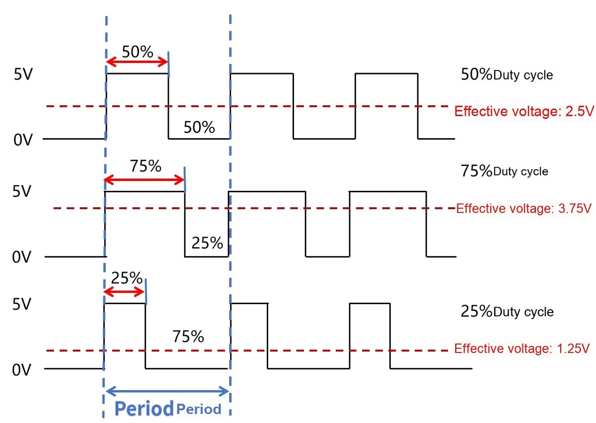
PWM, whose English name is Pulse Width Modulation, is the abbreviation of pulse width modulation. It modulates the width of a series of pulses to equivalently generate the required waveforms (including shape and amplitude), and digitally encodes analog signal levels. In other words, it adjusts the changes of signals, energy and others by regulating the variation of the duty cycle, which refers to the percentage of the time the signal stays at high level in a full signal cycle. For example, the duty cycle of a square wave is 50%.
A PWM signal has the following parameters:
- Period: A complete cycle of a PWM signal, consisting of the high-level duration and low-level duration of one pulse.
- Duty Cycle: The percentage of time a signal remains at a high level within a full cycle; the duty cycle determines the average output voltage.
- Frequency: The number of cycles of a PWM signal per second, usually expressed in hertz (Hz)
In PWM, although the pulse itself is a square wave, by adjusting the duty cycle, the effective voltage or power perceived by the load receiving the PWM signal (such as motors, LEDs, etc.) can be simulated into a desired continuously varying value. This technology enables digital hardware (such as microcontrollers) to efficiently and precisely control analog circuits, especially in scenarios requiring flexible adjustment of output levels, such as motor control, LED dimming, audio signal generation, and the like:
- Motor Control: By adjusting the duty cycle of the PWM signal, the speed and direction of the motor can be precisely controlled
- LED Dimming: Changing the duty cycle of the PWM signal allows for adjusting the brightness of the LED
- Audio signal generation: PWM can be used to synthesize audio signals and is widely applied in audio devices
- Power Management: The switching power supply regulates the output voltage and current via PWM to improve energy efficiency
1.2 Basic Structure and Concepts of Timers
The clock serves as the "fundamental beat" for the operation of all hardware (including timers) on the Raspberry Pi Pico: different peripherals require clocks of varying frequencies to function, and the clock system of the Pico operates in two steps:
- Clock source acquisition: Acquire raw clock signals from multiple stable "basic clock sources"(e. g., crystal oscillators, oscillators);
- Clock distribution : After the original clock signal undergoes "frequency division (frequency reduction) and enable (switch control)", it is distributed to different peripherals (such as timers, UARTs, ADCs).
Next, we will provide a basic introduction to the fundamental structures and concepts of the general-purpose timer, PWM timer, and Systick system tick timer. In the Raspberry Pi Pico, in addition to the common general-purpose timer, PWM timer, Systick system tick timer, RTC real-time clock, and WDT watchdog timer, the following peripherals also have their own independent timers:
- PIO finite-state machine: It features a 32-bit timer capable of generating interrupts, whose frequency equals the system clock frequency (clk_sys, the core clock for the processor and bus, typically 125MHz);
- DMA: It has four internal pacing timers that operate independently, and their clock is correlated with the clock of the DMA peripheral (typically clk_peri).
1.2.1 General-purpose Timer
The general-purpose timer of the Raspberry Pi Pico has the following features:
- 64-bit standalone increment counter: with a fixed frequency of 1MHz, the count increments by 1 every 1 microsecond;
- 4 alarms: An interrupt is generated when the lower 32 bits of the 64-bit counter match the value set in the alarm register;
- The counter can be read from a pair of latch registers, so there is no need to consider race conditions when multiple processors access it simultaneously.
The clock input of the general-purpose timer is provided by the watchdog timer at a frequency of 1MHz:
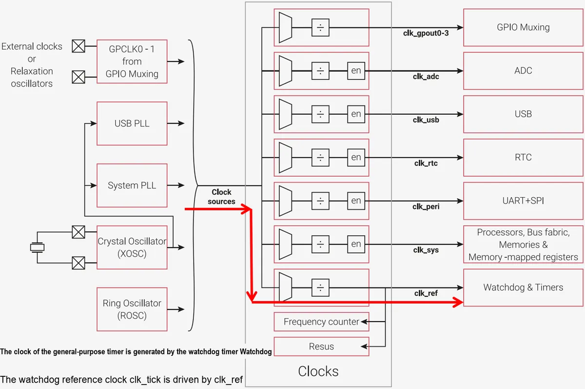
The red module on the left side of the diagram is Pico's "raw clock source", which provides base clocks with different characteristics:
- Crystal Oscillator (XOSC): An external crystal oscillator (typically 12 MHz), which serves as the most stable clock source;
- Ring Oscillator (ROSC): An on-chip ring oscillator featuring fast startup yet relatively low accuracy.
- USB PLL/System PLL: Phase-locked loop circuits that can multiply the base clock to a higher frequency (for example, the System PLL can output a 125MHz signal as the system core clock);
- GPCLK0-1: External clock input multiplexed from GPIO pins;
- External clocks/Relaxation oscillators: Other external clocks or relaxation oscillators.
The module on the right side of the diagram is the "Clock Distribution Unit": it selects a clock source from the "Clock sources" on the left, adjusts the frequency via the "frequency divider (marked as ÷ in the diagram)", controls on/off through the "enable switch (en)", and then sends the clock to the corresponding peripheral. The key association related to timers among them is:
- clk_ref clock: assigned to the "Watchdog & Timers";
- Clock of the general-purpose timer: It is obtained after the clk_ref is processed by the watchdog, with a frequency of 1MHz.
1.2.1.1 Counter Unit
The timer features a 64-bit counter, yet the RP2040 only has a 32-bit data bus. This means that reading and writing the TIME counter value each require operations via a pair of registers (the base address of the timer registers is TIMER_BASE 0x40054000):
- Write the time via the TIMEHW register (for writing upper 32-bit data) and the TIMELW register (for writing lower 32-bit data):
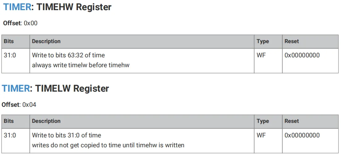
- Use the TIMEHR register (to read the upper 32 bits of data) and the TIMELR register (to read the lower 32 bits of data) to read the time:
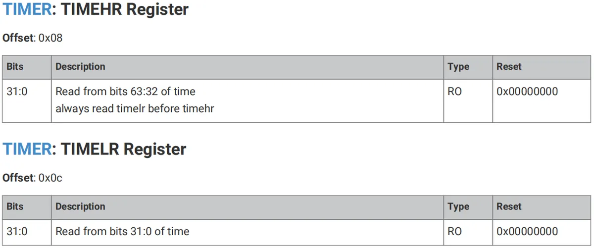
It should be noted that although it is theoretically possible to enforce a new time value by writing to the TIMEHW and TIMELW registers, this practice is discouraged. This is because the timer value is expected to be incremented monotonically by the Pico SDK.
1.2.1.2 alarm alarm unit
The timer has 4 alarm units, each of which can output an independent interrupt. Since the alarm units match the lower 32 bits of the 64-bit counter, the upper time limit for the alarm unit timing is 2^32 us = 4295 s = 72 min.
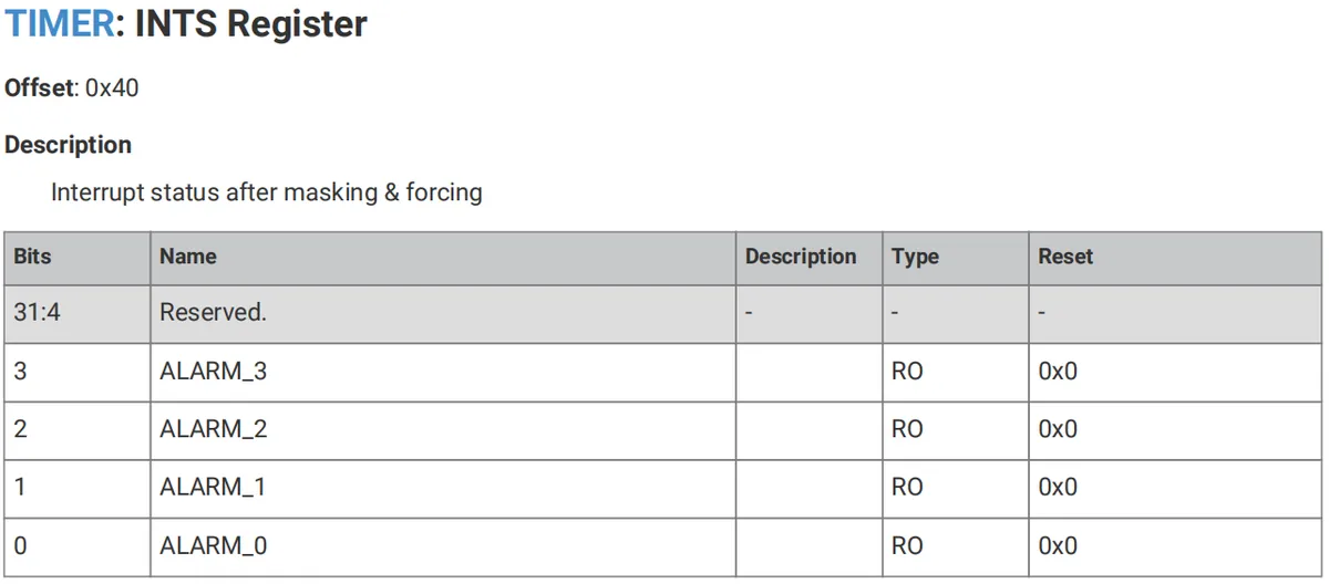
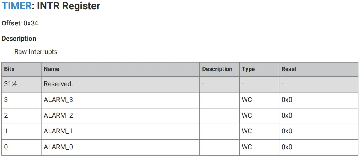
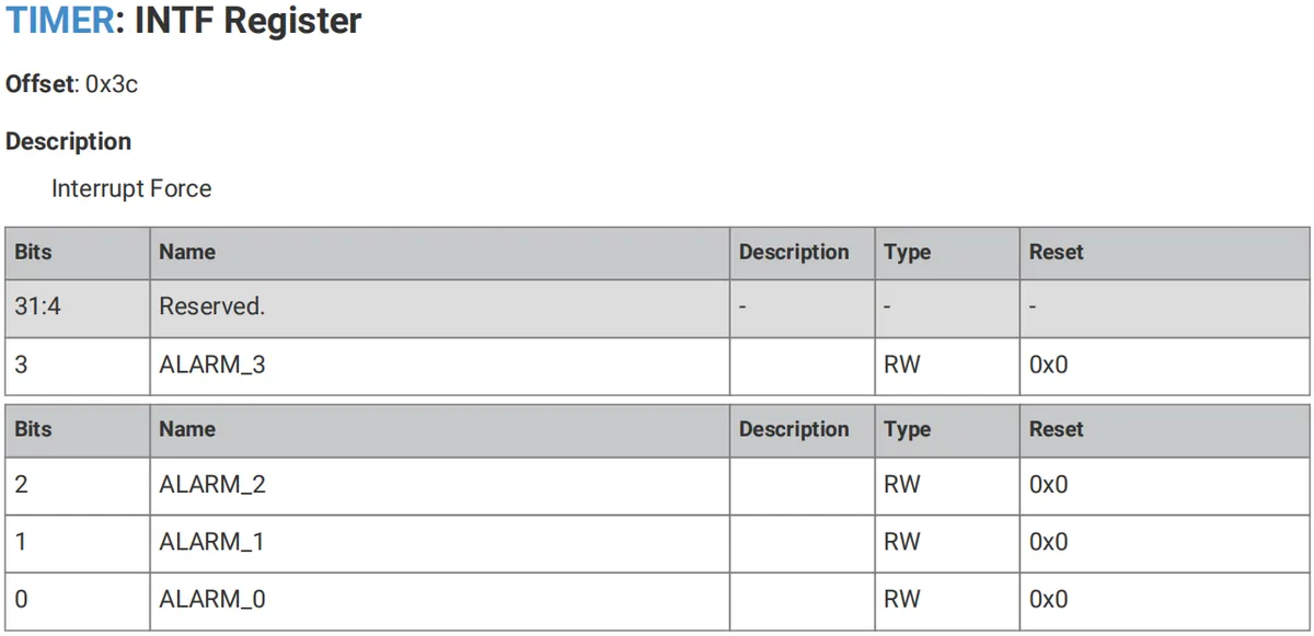
If you need to enable the alarm unit, you need to configure the following registers: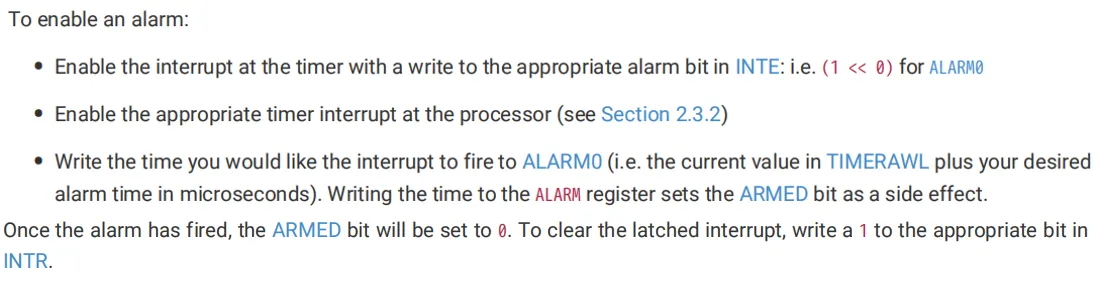
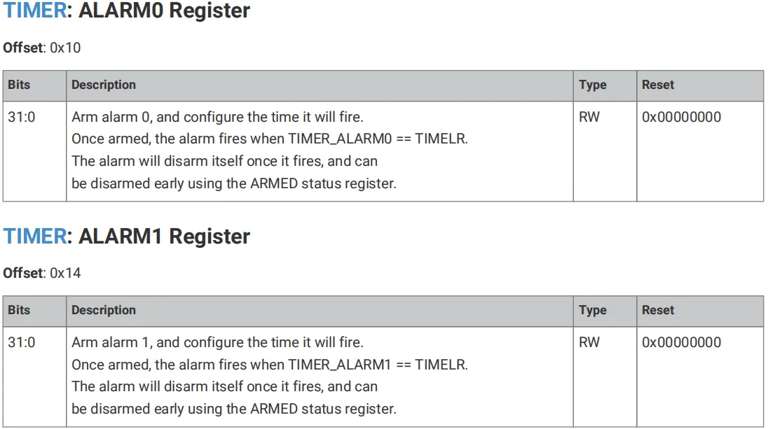
- ALARMx (x = 0~3) Registers: Used to set the alarm time; when the set time is reached, a fire event will be triggered and an alarm will be generated.
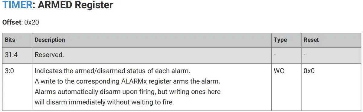
- ARMED register: indicates whether each alarm generates an alert
- INTE register: enable or disable the alarm interrupt
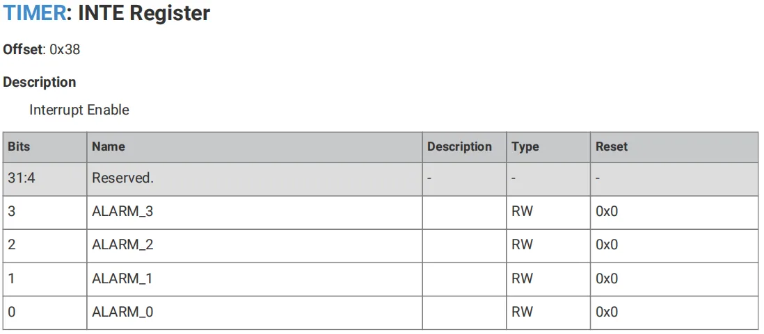
- INTR Register, INTF Register, INTS Register: Check the alarm interrupt status or force an interrupt to be generated
1.2.2 PWM Timer
1.2.2.1 Basic Structure and Characteristics of PWM Timer
The PWM timer comprises 8 "nearly independent" 16-bit programmable counters, which share the same 125 MHz input clock (system clock) but feature mutually independent clock dividers.
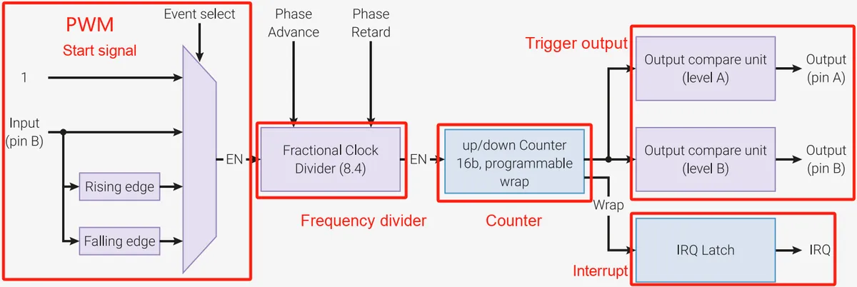
The PWM timer of the Raspberry Pi Pico has the following features:
- Each counter channel has two outputs (16 PWM channels in total), which can be connected to any of all GPIO pins.
- The frequency divider features 8-integer and 4-decimal frequency division, and the signal output frequency adjustable via 16-bit PWM ranges from 125 MHz to 7 Hz.
- The adjustable duty cycle range for each PWM output channel is 0 to 100.
- can generate interrupt requests or trigger DMA
- Of the two channels of each counter, one can be used as an input to serve as the start signal for the PWM output; this input supports rising-edge triggering, falling-edge triggering or high-level triggering, and this function can be applied to measure the frequency and duty cycle of external signals.
- Phase is adjustable when the timer increments
- All channels can be started synchronously and permitted to operate, so as to perform power control.
The correspondence between each GPIO and the PWM channel is as follows:

You can select the same PWM output for two GPIO pins; the identical signal will appear on each of the GPIOs.
1.2.2.2 Start Signal of PWM Channel
Here, the B pin of the PWM channel can be used as the start signal for PWM. It should be noted that when the B pins of multiple PWM channels are used simultaneously, the signals on these B pins will undergo an OR operation before being used as the PWM start signal.
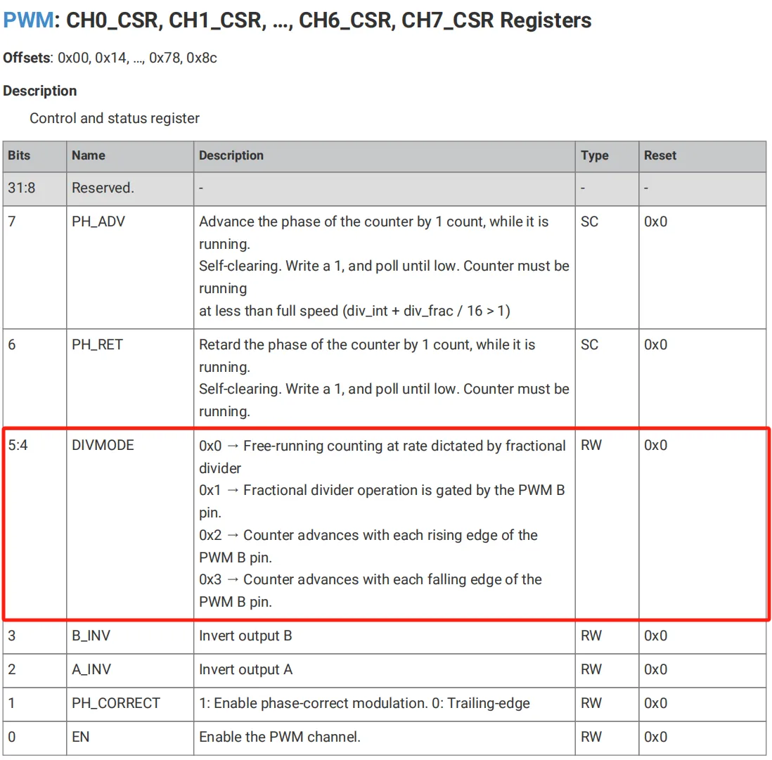
We can configure the DIVMODE bits in the CSR register to select rising-edge triggering, falling-edge triggering or high-level triggering:
1.2.2.3 Working Principle and Counting Modes of PWM Timer
Simply put, the operating principle of a PWM timer is as follows: there is a timer inside the PWM that increments with each clock cycle, and after each increment, it compares the current count value of the counter with the preset count value: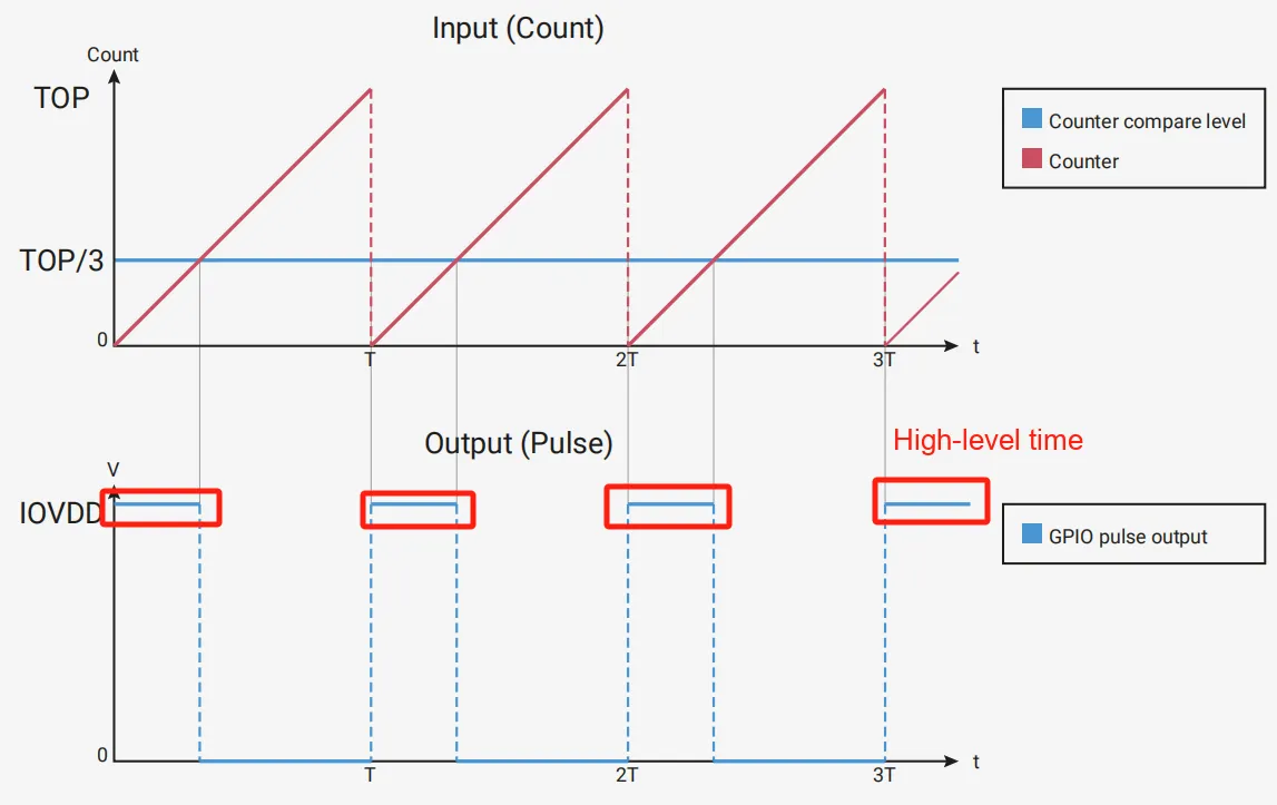
- the count value of the current counter <preset count value:the GPIO pin corresponding to the PWM channel outputs a high level
- When the count value of the current counter is greater than the preset count value: the GPIO pin corresponding to the PWM channel outputs a low level
The figure above shows the up-counting mode of the PWM timer (the output goes low when the set value is reached), and the PWM timer also supports the center-aligned counting mode:
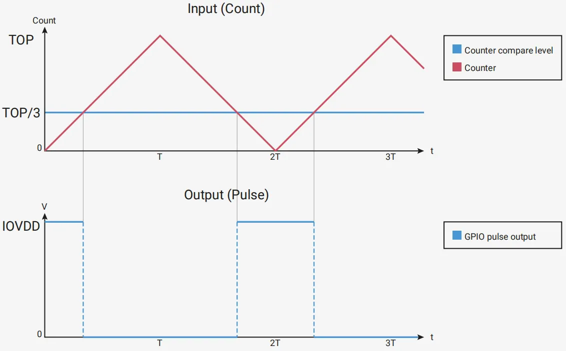
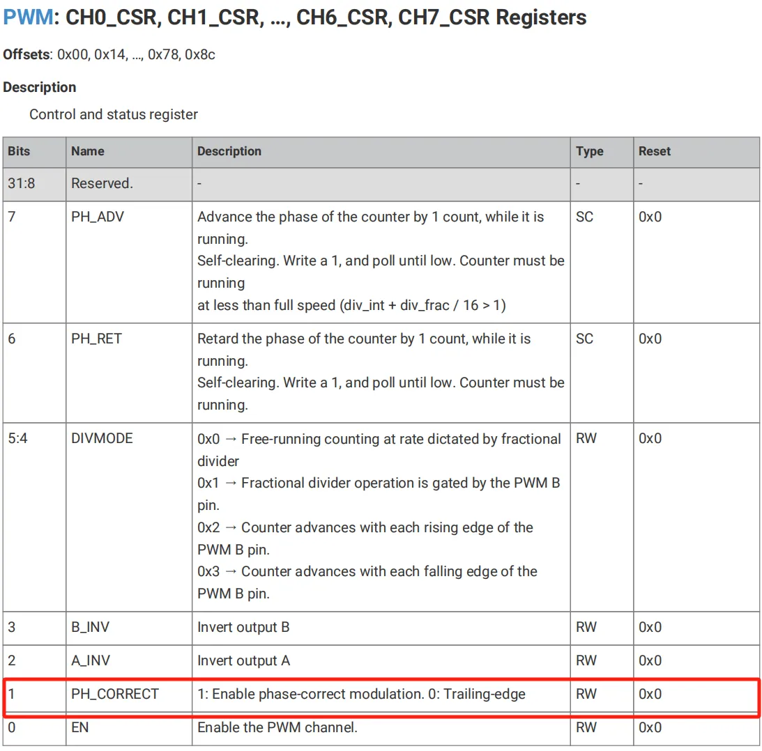
The two counting modes can be switched via the PH_CORRECT bit of the CSR register:
1.2.2.4 Modification of PWM Parameters
Here, the counting period (i. e., the maximum count value) of the PWM timer is controlled by the TOP register, with a maximum period of 65536 clock cycles; the comparator value of the counter is controlled by the CC register, and the clock division is controlled by the DIV register.
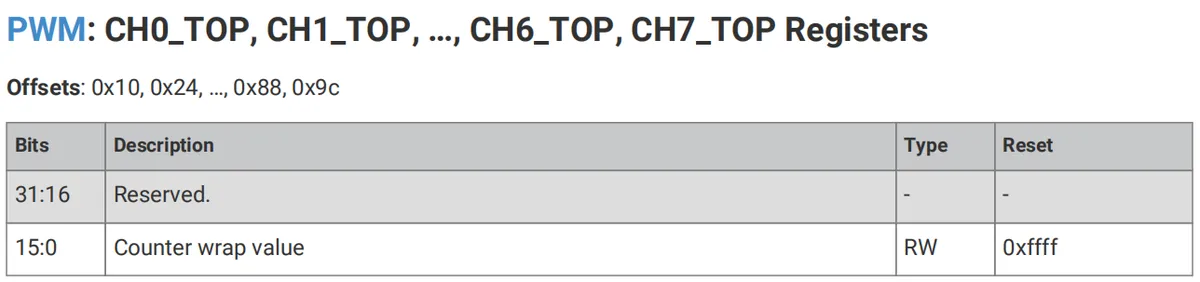
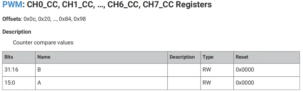
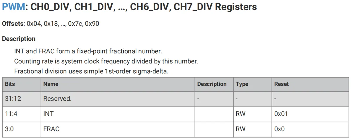
The PWM output period and frequency can be calculated using the following formula:


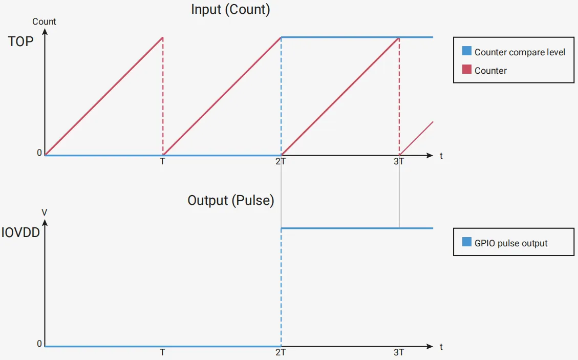
The output duty cycle of the PWM timer can vary between 0% and 100%; a CC value of 0 produces a 0% output, while a CC value equal to TOP + 1 produces a 100% output:
1.2.2.5 Dual Register Mechanism of PWM Timer
Here, it should be noted that the TOP register and CC register of the PWM timer feature a dual-register mechanism. Simply put, the TOP register and CC register actually consist of the following parts: a preload TOP register, a shadow TOP register, a preload CC register, and a shadow CC register. The shadow register is the one that actually functions, while the preload register serves as a buffer for the shadow register to prepare data or instructions in advance.Since timers usually operate with a certain periodicity, if every parameter modification we make is directly applied to the actual registers, it will inevitably interfere with the normal counting of the current cycle and the related output operations.
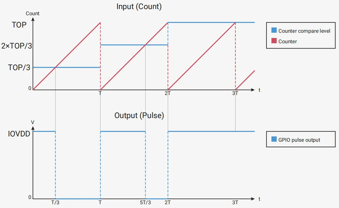
Consider this scenario: when we need to switch the duty cycle of PWM, we have to modify the value in the timer CC register. The ideal situation we expect is as shown in the figure below: when we modify the value in the timer CC register, there is a high probability that the current PWM timer is already in the middle of a counting cycle. What we expect is that the duty cycle of the PWM wave output within the current cycle follows the value preset in the last time, and only when the counter starts a new counting cycle will the output PWM wave generate a PWM wave with the corresponding duty cycle according to the newly set counting threshold this time:
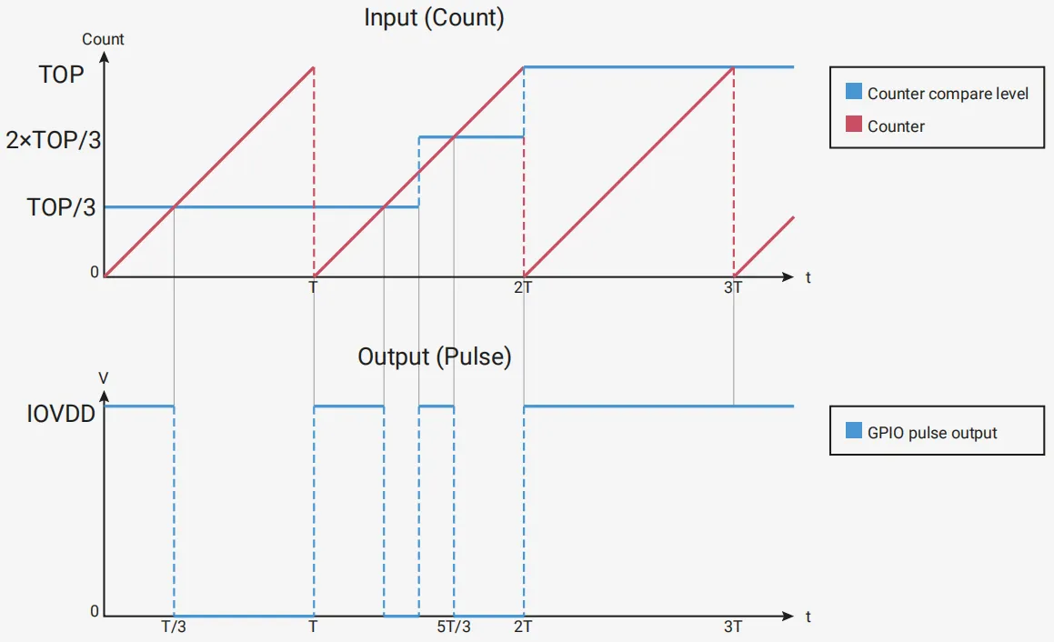
If the dual-register mechanism is not adopted, the count value preset by the user via software will be immediately updated to the CC register of the timer, which will cause abnormalities in the output of the PWM waveform:
Here, it should be noted that what users always operate via the software are only the preload registers. After we modify the value in the preload register, the shadow register will not immediately copy the value from the preload register; instead, it will transfer the value from the preload register to the shadow register until the next update event occurs: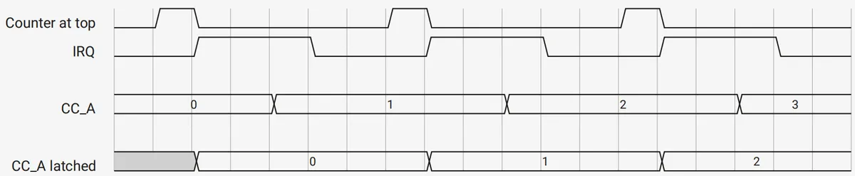
- When the timer operates in upcounting mode: When the counter reaches the preset count threshold, the count value is cleared to generate an update event.
- When the timer operates in center-aligned mode: An update event is generated when the counter stops counting down and resumes counting up again.
1.2.3 Systick System Tick Timer
1.2.3.1 Introduction to Systick Timer
The SysTick timer, also known as the system tick timer, is a timer embedded in the Cortex-M0 core. All microcontroller units (MCUs) based on ARM Cortex-M series cores are equipped with this timer. Implementing delay functions or the heartbeat clock of a real-time operating system (RTOS) using the core's SysTick timer does not occupy the system timer, thus saving system resources. Since SysTick is implemented inside the CPU core and is independent of MCU peripherals, its code can be ported across MCUs from different manufacturers.
The Systick timer in the Raspberry Pi Pico has the following features:
- It is a 24-bit down-counting timer
- Additional configurable priority SysTick interrupt
- The frequency is 1MHz, with a count performed once every 1 microsecond.
1.2.3.2 Control the Systick timer
The SysTick timer is mainly controlled by the following four registers (the base address of the Cortex-M0 core is PPB_BASE 0xe0000000):
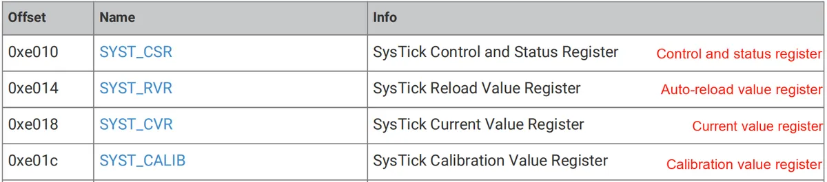
Simply put, the working principle of the SysTick timer is that it counts down continuously; when the current count value reaches 0, it automatically loads the initial timing value from the auto-reload register, and then starts the next counting cycle.
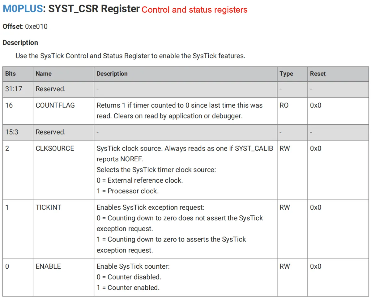
For the SYST_CSR register, it has the following four bits:
- COUNTFLAG bit: Its primary function is to prevent misreading and over-reading. If the SysTick has counted down to 0 since the last time this bit was read, the value read this time will be 1; conversely, if this bit was not read last time, it will be automatically cleared immediately after being read.
- CLKSOURCE bit: It is mainly used to select the clock source, and either an external clock or the system clock can be selected.
- TICKINT bit: Its main function is to select whether to generate an interrupt after the countdown ends.
- ENABLE bit: disables or enables the Systick timer
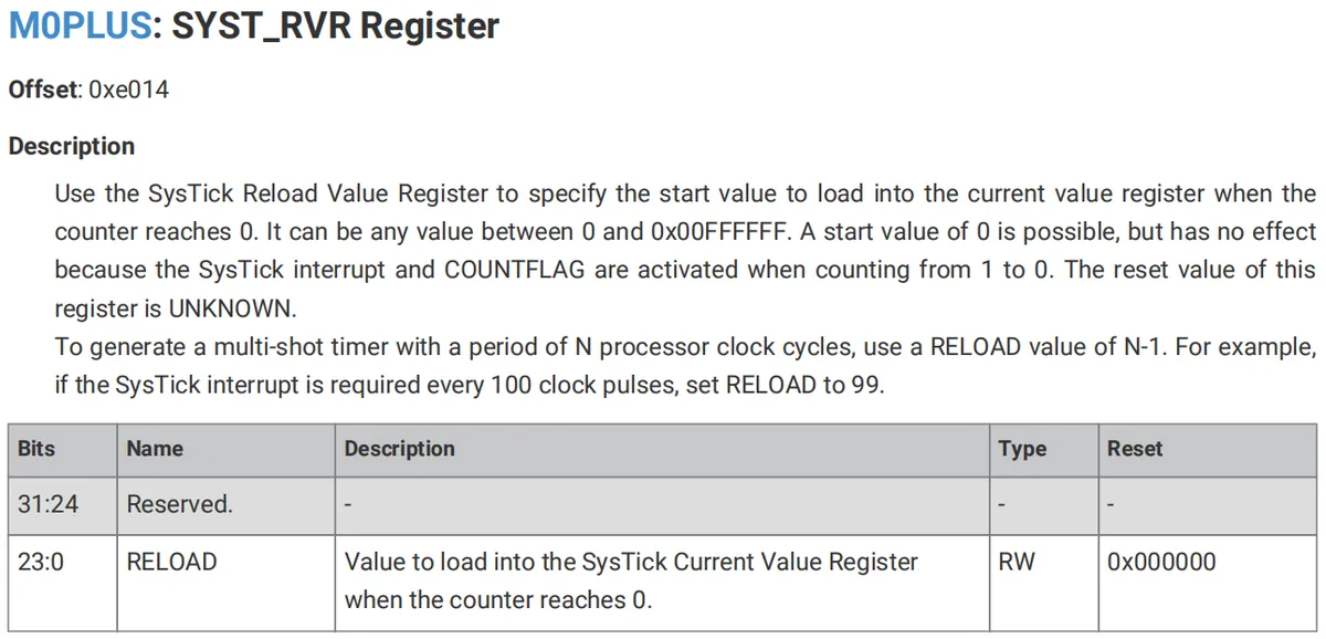
Use the SysTick SYST_RVR register to specify the start value to be loaded into the current value register when the counter reaches 0. It can be any value between 0 and 0x00FFFFFF; when counting from 1 down to 0, the SysTick exception request and the count flag will be activated. :
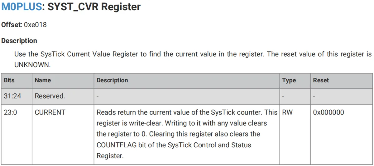
SYST_CVR can be used to obtain the current count value, and writing any value to it will clear the register to 0. Clearing this register will also clear the COUNTFLAG bit in the SysTick Control and Status Register:
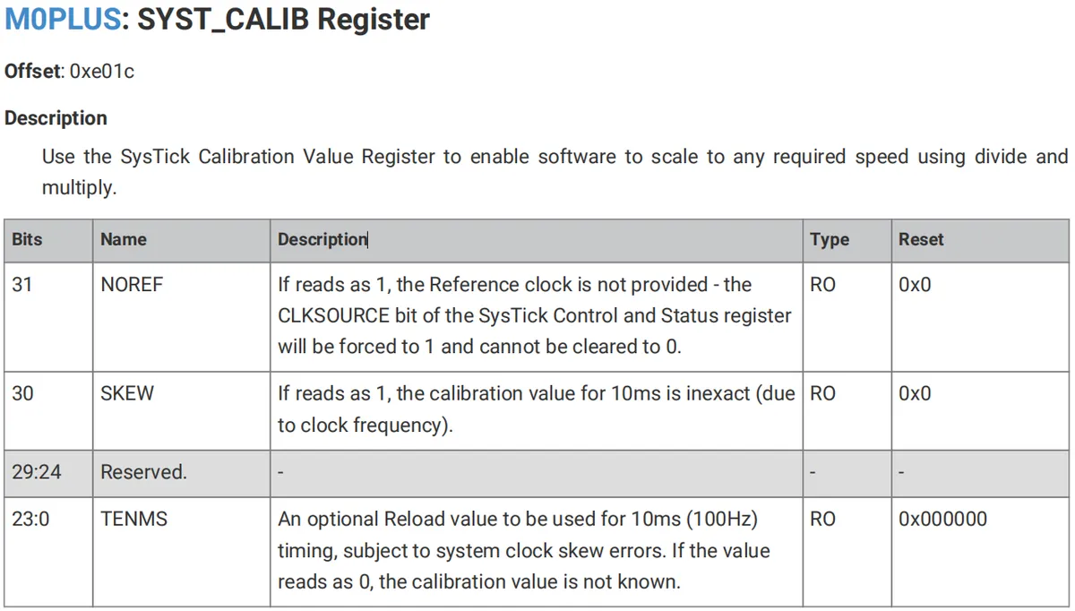
Calibrate or obtain the calibration status using the SysTick calibration value register:
1.3 Overview of Timers on Raspberry Pi Pico
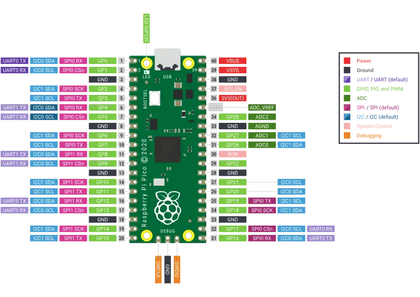
Simply put, the Raspberry Pi Pico features the following timing units:
- One 64-bit general-purpose timer with independent increment and a frequency of 1 MHz
- 8 16-bit programmable PWM timers, with all pins capable of generating PWM signals
- 1 Systick system tick timer
- A down-counting watchdog timer
- 1 RTC (Real-Time Clock)
- A 32-bit timer capable of generating interrupts inside the PIO finite-state machine, whose frequency equals the system clock frequency
- The DMA contains four internal pacing timers that can trigger transmissions at regular intervals.
2. Software Control Method
2.1 Constructor of the machine.Timer class
The constructor of the machine.Timer class is as follows:
class machine.Timer(id, ...)
Construct a software timer object with the given parameters
The parameters are defined as follows:
- id - On the Raspberry Pi Pico, all timers are "virtual" and implemented in software. All virtual timers have an ID of -1, so there is no need to specify a timer ID. In MicroPython on the RP2040, there is no limit to the number of timers other than the requirement that sufficient available memory exists. Since there are no specific hardware limitations, these timers are commonly referred to as "virtual" timers. The number of virtual timers is limited by the amount of memory available to the microcontroller.
2.2 Other Methods of the machine.Timer Class
The machine.Timer class also has initialization and deinitialization methods:
Method | Description |
Timer.init (*, mode=Timer.PERIODIC, freq=-1, period=-1, callback=None) | Initialize the timer with the given parameters, and the initialization method is as follows:
|
Timer.deinit() | Cancel the initialization of the timer and stop the timer. |
2.3 Constructor method of the machine.PWM class
The constructor of the machine.PWM class is as follows:
classmachine.PWM(dest, *, freq, duty_u16, duty_ns, invert)
Construct a PWM timer object with the given parameters
The parameters are defined as follows:
- dest - the pin that outputs PWM, which is usually a machine.Pin object
- freq - should be an integer, which is used to set the frequency of the PWM cycle (in Hz)
- duty_u16 - sets the duty cycle to the ratio of duty_u16 / 65535
- duty_ns - Set the pulse width (in nanoseconds)
- invert - If the value is True, the corresponding output will be inverted
2.4 Other methods of the machine.PWM class
The other methods of the machine.PWM class are as follows:
Method | Description |
PWM.init(\*, freq, duty_u16, duty_ns) | Modify the settings of the PWM object |
PWM.deinit() | Disable PWM output |
PWM.freq([value]) | Get or set the current frequency of the PWM output:
|
PWM.duty_u16([value]) | Gets or sets the current duty cycle of the PWM output:
|
PWM.duty_ns([value]) | Gets or sets the current pulse width of the PWM output, in nanoseconds:
|
3. Application Examples
3.1 Key Detection Finite-State Machine Framework Implemented by Timer
3.1.1 Basic Principles of the Key Detection Finite-State Machine Framework
3.1.1.1 Types of Key Operations
Key operations can be broken down into the following categories:
- Long press: Press and hold the button; in this context, a press-and-release action lasting longer than 1.2 seconds is defined as a long press
- Short press: Press and hold the button for a short period
- Single Click: Press and release a button; here we define a single click as an action where the press duration is less than 1 second, and no subsequent press occurs within 500ms after the button is released
- Double-click: Two single-click operations with an interval of less than 500ms are combined into a double-click
3.1.1.2 Basic Concepts of Finite-State Machine
Before explaining the finite-state machine, we first need to understand what a state is. A state refers to the form manifested by a person or a thing, that is, the form or situation of a real (or virtual) thing when it is in the stages of generation, existence, development, extinction, or at the critical points of various transitions. Simply put, it is the various forms corresponding to an object under different circumstances.
A finite-state machine (Finite State Machine, abbreviated as FSM) is a mathematical model used to describe the states an object undergoes during its lifecycle and how transitions occur between these states. It consists of a set of states, an initial state, a set of input events, and a state transition function. When a certain input event is received, the finite-state machine will determine which new state to transition to based on the current state and the input event, and may generate an output. Finite-state machines have a wide range of applications in computer science, such as compiler design, network protocol analysis, game AI, etc.
For example, the switch of a small light bulb is a most basic small finite-state machine:
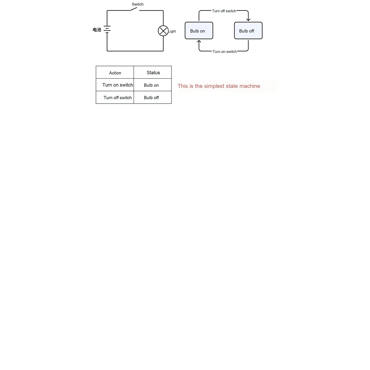
The convenience of a finite-state machine is that, if we currently only have two states, which transition between the two conditions of toggling the switch on and off, and we want to add a new condition — for example, we set a timer to turn the light on and off, adding an extra transition condition that the bulb will automatically turn off if it has been on for more than 8 hours, and will remain off unless the switch is toggled on again — the corresponding state diagram is as follows:
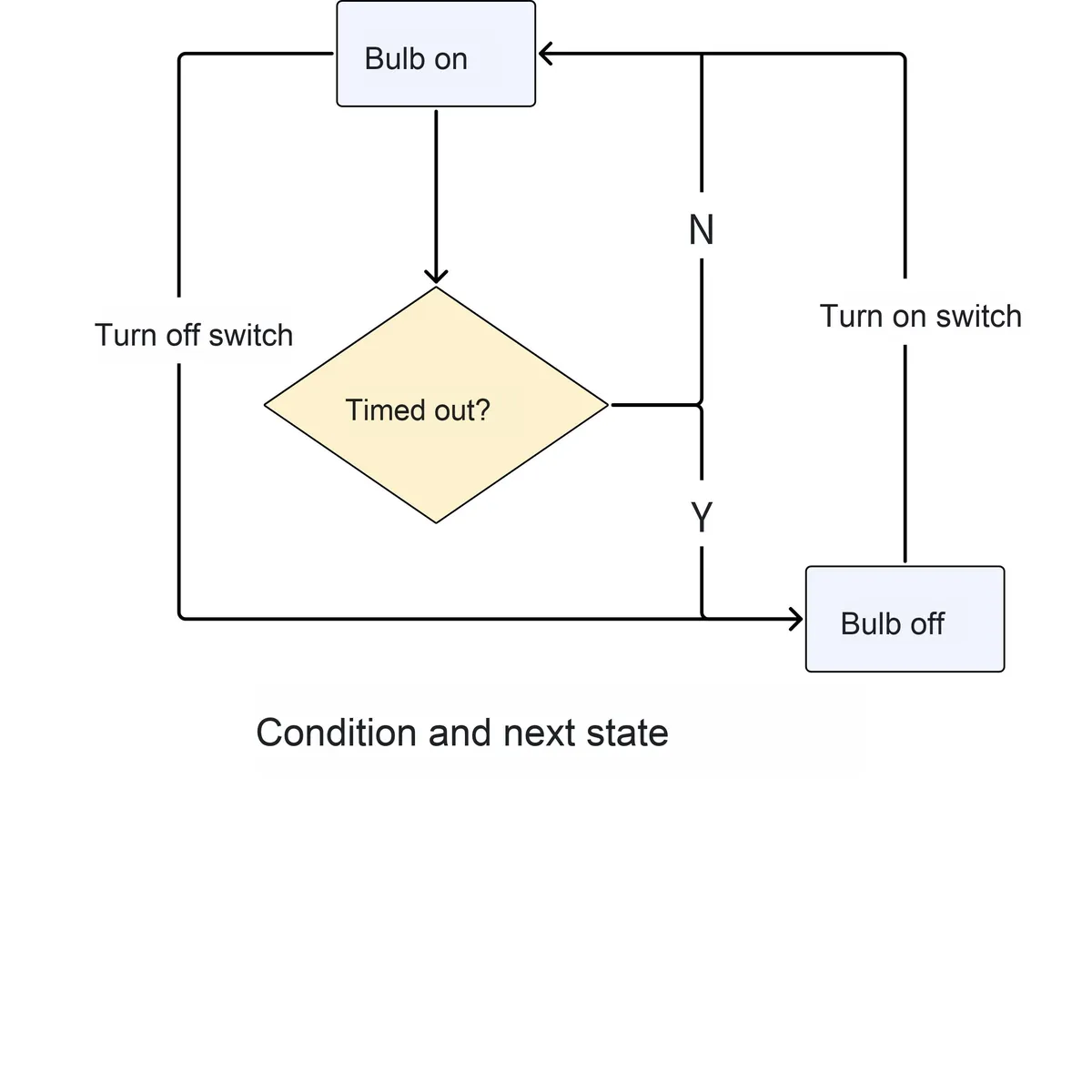
Based on the above overview, we can see that a finite-state machine can be summarized as current state, condition, action, next state four core elements, among which "current state" and "condition" are the "causes", and "action" and "next state" are the "results". The detailed description of each element is as follows:
- Present State: refers to the state that a system is currently in.
- Condition (also referred to as "event"): When a given condition is met, it will trigger an action or execute a state transition.
- Action: An operation to be performed when a condition is met. After the action is completed, the system can either transition to a new state or remain in the original state (actions are not mandatory — when a condition is satisfied, the system may also directly transition to a new state).
- Next state: the new state to transition to once the conditions are met; once activated, the "next state" will become the new "current state".
Since the states of a common finite-state machine are all discrete and enumerable, meaning they are finite, the finite-state machine we use is also known as a finite-state machine.
We typically use state transition diagrams (STD) and state transition tables to describe the set of states, events and behaviors of a finite-state machine:
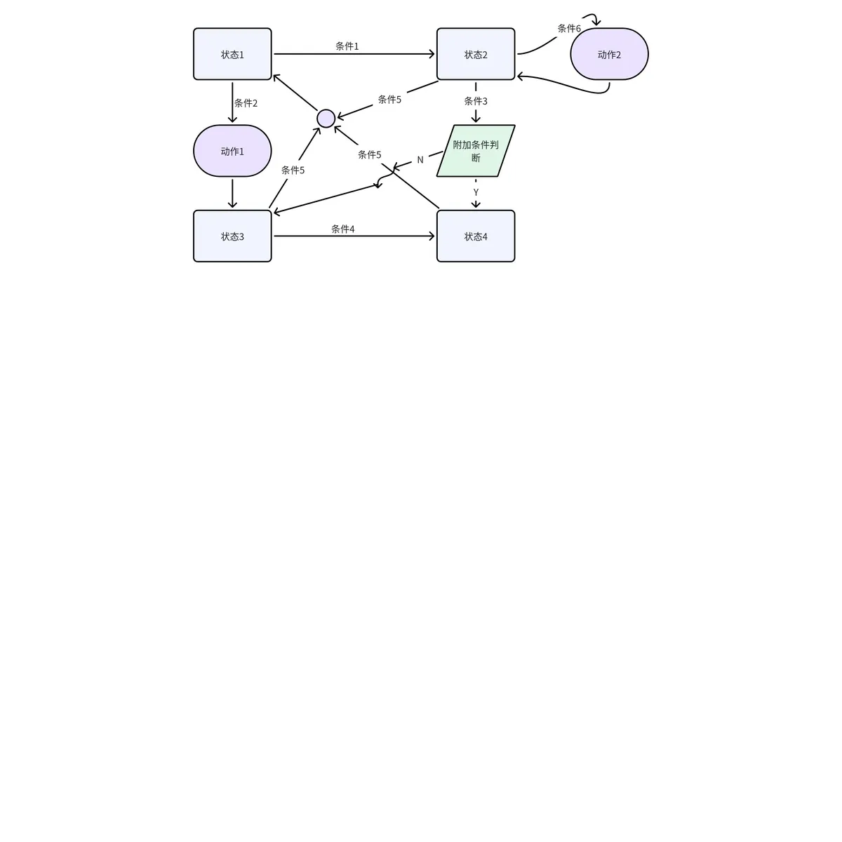
State (Current State) | Status Description | Conditions | Action | post-state | |
|---|---|---|---|---|---|
Status 1 | …… | Condition 1 | - | State 2 | |
Condition 2 | Action 1 | Status 3 | |||
State 2 | …… | Condition 3 | Additional conditions: Met | - | Status 4 |
Additional conditions: Not satisfied | - | Status 3 | |||
Condition 5 | - | Status 1 | |||
Condition 6 | Action 2 | - | |||
Status 3 | …… | Condition 4 | - | Status 4 | |
Condition 5 | - | Status 1 | |||
Status 4 | …… | Condition 5 | - | Status 1 | |
3.1.1.3 Basic Implementation of the Key Detection Finite-State Machine
Simply put, the principle of the key detection finite-state machine is as follows: periodically detect whether the key is pressed or released (here we refer to these as the press action and the release action), and perform state transition according to the key action and the current state:
- When the key is in the clicked state and released within the specified time: A click operation is completed, and the corresponding callback function is executed
- When the key is in the long-press state and then released: A long-press operation is completed, and the corresponding callback function is executed
- When the key is in the double-click state and released within the specified time: a long press operation is completed, and the corresponding callback function is executed
As is known to all, a key can perform two actions: being pressed and being released.
We first define the key operations as follows:
- Long press: Press and hold the button; in this context, a press-and-release action lasting longer than 1.2 seconds is defined as a long press
- Short press: Press and hold the button for a short period
- Single Click: Press and release a button; here we define a single click as an action where the press duration is less than 1 second, and no subsequent press occurs within 500ms after the button is released.
- Double-click: Two single-click operations with an interval of less than 500ms are combined into a double-click
In the chapter on GPIO, we mentioned that there is bouncing when a key is pressed, and we can divide the keys into the following states:
- Release Status: It covers two scenarios: no key being pressed, and a key being released after being pressed.
- Debounce Status: Jitter occurs within 20ms after a key press action, and this period is defined as the debounce status
- Click Status: After the debounce state, if the key remains pressed in the next detection and the pressing duration is less than 1.2 seconds, it is defined as a click status
and it is required that no key is pressed again within 500ms after release
- Long press status: It is defined as the long press status when the previous status of the key is a single click status and the pressing duration exceeds 1.2 seconds.
- Waiting state: When the previous state of a key was pressed, the period within 500ms after the key is released before any new key press event occurs is defined as the waiting state.
- Double-click status: When the previous state of a key was pressed, and the key is pressed again within 500ms after being released, it is defined as the double-click status
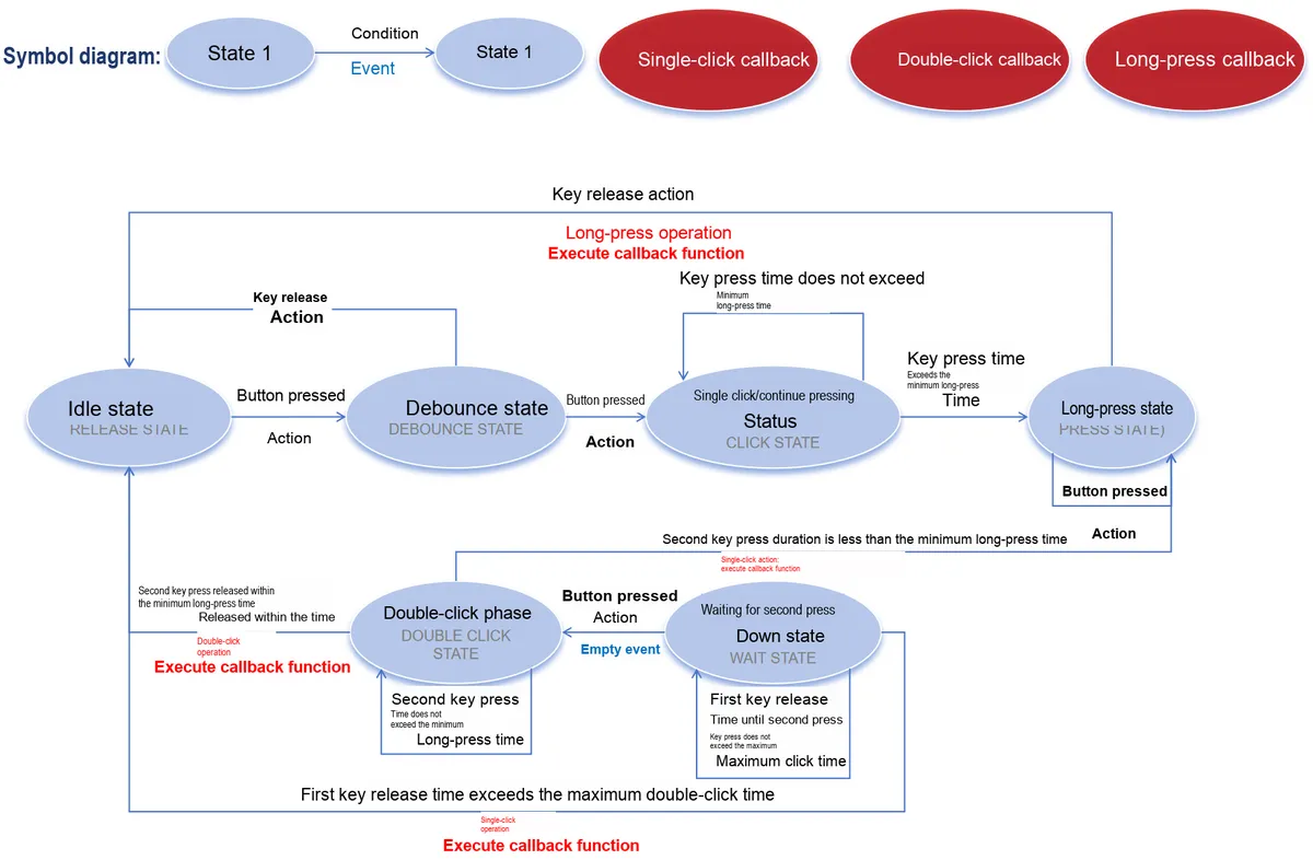
Here, we first define the Button class and a series of class attribute constants in the key press detection finite-state machine:
# Button state machine framework
class ButtonFSM:
    """
    ButtonFSM class, used to implement a button state machine that detects button events such as press, release, long press and double click.

    This class encapsulates the button state machine logic and supports detecting operations such as long press, single click and double click. A timer periodically checks the button state for changes,
    and handles events according to the button state. The user can obtain button actions through callback functions.

    Attributes:
        LOW (int): Low-level state of the button, indicating the button is not pressed.
        HIGH (int): High-level state of the button, indicating the button is pressed.
        BtnPressMinTime (int): Minimum time for a button long press (unit: milliseconds). When the button is held longer than this value, it is considered a long press.
        BtnDoubleClickMaxTime (int): Maximum time interval between two clicks in a double-click event (unit: milliseconds).
        RELEASE_EVENT (int): Button release event.
        CLICK_EVENT (int): Button click event.
        RELEASE_STATE (int): Button release state.
        DEBOUNCE_STATE (int): Button debounce state.
        CLICK_STATE (int): Button click state.
        WAIT_STATE (int): Button waiting-for-second-click state.
        DOUBLE_CLICK_STATE (int): Button double-click state.
        PRESS_STATE (int): Button long-press state.

    Methods:
        __init__(self, pin: Pin, timer: Timer, init_state: int,
                 press_callback: callable, click_callback: callable,
                 double_click_callback: callable, args: object = None) -> None:
            Initialize a ButtonFSM class instance, setting the button pin, timer and callback functions.

        detect(self, timer: Timer) -> None:
            Button state detection function. It determines the button action from the current button state and signal, and updates the button state.

        get_action(self) -> None:
            Get the current button action (such as click or release) and update the button state.
    """
    # Button initial state: low level-0 when initialized, high level-1 when pressed
    LOW, HIGH = (0, 1)
    # Minimum time to confirm a long press: when the press time is greater than this value, the button is considered long-pressed
    BtnPressMinTime = 1200
    # Maximum interval between two clicks in a double click: when the interval between two clicks is less than this value, the button is considered double-clicked
    BtnDoubleClickMaxTime = 500

    # Button state machine definitions
    # Button events: release or press
    RELEASE_EVENT,CLICK_EVENT = (0, 1)
    # Button states: release, debounce, click/continue pressing, wait for second press, double click, long press
    RELEASE_STATE, DEBOUNCE_STATE, CLICK_STATE, WAIT_STATE, DOUBLE_CLICK_STATE, PRESS_STATE = (0, 1, 2, 3, 4, 5)
We define both key press events and states as class attributes, and the variables in this section are available in every instance of the Button class.
In the initialization method of the Button class, we need to pass in the pin used by the button, the timer object, the initial state of the button (high level or low level), the long press callback function, the short press callback function and the double-click callback function:
def __init__(self, pin: Pin, timer: Timer, init_state: int,
             press_callback: callable, click_callback: callable,
             double_click_callback: callable, args: object = None) -> None:
    """
    Initialize the button, setting the button state, pin, callback functions and timer.

    Args:
        pin (machine.Pin): Pin object the button is connected to.
        timer (machine.Timer): Timer object used to periodically check the button state.
        init_state (int): Button initial state (low level or high level), optional values are ButtonFSM.LOW or ButtonFSM.HIGH.
        press_callback (callable): Callback function triggered by a long press.
        click_callback (callable): Callback function triggered by a single click.
        double_click_callback (callable): Callback function triggered by a double click.
        args (object, optional): Extra argument for the callback functions, default value is None.

    Returns:
        None

    Description:
        This method initializes the button to low level or high level, and sets the timer to call the `detect` method periodically to check the button state.
    """

    self.pin = pin
    self.timer = timer
    self.init_state = init_state
    self.press_callback = press_callback
    self.click_callback = click_callback
    self.double_click_callback = double_click_callback

    # Initialize the button pin
    # Button initial state is low level-0, high level-1 when pressed
    if self.init_state == ButtonFSM.LOW:
        self.pin.init(self.pin.IN, self.pin.PULL_DOWN)
        self.pin_signal = Signal(self.pin, invert=False)
    # Button initial state is high level-0, low level-1 when pressed
    elif self.init_state == ButtonFSM.HIGH:
        self.pin.init(self.pin.IN, self.pin.PULL_UP)
        self.pin_signal = Signal(self.pin, invert=True)

    # Button long-press count: whether the button is long-pressed is determined by long-press count * timer period
    self.press_count = 0

    # Button event
    self.event = ButtonFSM.RELEASE_EVENT
    # Button state
    self.state = ButtonFSM.RELEASE_STATE

    # The timer runs continuously with a 20ms period, and calls the detect method to check the button state when the set time is reached
    self.run_period = 20
    self.timer.init(period=self.run_period, mode=Timer.PERIODIC, callback=self.detect)

    # Callback function argument
    self.args = args
Here, the timer is configured to trigger periodically with a period of 20ms. Each time the timer triggers, the detect method is called to check the key state.
def detect(self, timer: Timer) -> None:
    """
    Button press state detection function. It determines the button action from the current button state and signal.

    Args:
        timer (machine.Timer): Timer object passed in, used to call the detection function periodically.

    Returns:
        None: This function has no return value; it updates the button state through internal events.
    """

    # Get the button action
    self.get_action()

    # State: no action
    if self.state == ButtonFSM.RELEASE_STATE:
        # Button pressed, enter the debounce state
        if self.event == ButtonFSM.CLICK_EVENT:
            self.state = ButtonFSM.DEBOUNCE_STATE
        # Button not pressed, enter the release state
        else:
            self.state = ButtonFSM.RELEASE_STATE

    # State: debounce
    elif self.state == ButtonFSM.DEBOUNCE_STATE:
        # Button pressed, enter the click state
        if self.event == ButtonFSM.CLICK_EVENT:
            self.state = ButtonFSM.CLICK_STATE
        # Button not pressed, enter the release state
        else:
            self.state = ButtonFSM.RELEASE_STATE

    # State: click/continue pressing
    elif self.state == ButtonFSM.CLICK_STATE:
        # Button is still pressed and the time exceeds BtnPressMinTime, the minimum time to confirm a long press
        if self.event == ButtonFSM.CLICK_EVENT and self.press_count*self.run_period >= ButtonFSM.BtnPressMinTime:
            # Button is in the long-press state
            self.state = ButtonFSM.PRESS_STATE
            self.press_count = 0
        # Button is still pressed and the time is less than BtnPressMinTime, the minimum time to confirm a long press
        elif self.event == ButtonFSM.CLICK_EVENT and self.press_count*self.run_period < ButtonFSM.BtnPressMinTime:
            # Continue timing
            self.press_count = self.press_count + 1
            # Stay in the click state
            self.state = ButtonFSM.CLICK_STATE

        # Button released after a short press, enter the wait-for-second-press state
        else:
            # Clear the count variable
            self.press_count = 0
            # Enter the wait-for-second-press state
            self.state = ButtonFSM.WAIT_STATE

    # State: long press
    elif self.state == ButtonFSM.PRESS_STATE:
        # Still pressed, wait for the button to be released and then convert to a long-press event
        if self.event == ButtonFSM.CLICK_EVENT:
            # Reset the button long-press count to zero
            self.press_count = 0
            # Button released, enter the release state
            self.state = ButtonFSM.PRESS_STATE
        else:
            self.press_count = 0
            self.state = ButtonFSM.RELEASE_STATE
            # Execute the long-press callback function
            if self.press_callback is not None:
                self.press_callback(self.args)

    # State: wait for second press
    elif self.state == ButtonFSM.WAIT_STATE:
        # First short press, and the release time is greater than BtnDoubleClickMaxTime, the maximum interval between two clicks in a double click
        if self.event == ButtonFSM.RELEASE_EVENT and self.press_count*self.run_period >= ButtonFSM.BtnDoubleClickMaxTime:
            self.press_count = 0
            self.state = ButtonFSM.RELEASE_STATE
            # Execute the single-click callback function
            if self.click_callback is not None:
                self.click_callback(self.args)

        # First short press, and the release time is less than BtnDoubleClickMaxTime, the maximum interval between two clicks in a double click
        elif self.event == ButtonFSM.RELEASE_EVENT and self.press_count*self.run_period < ButtonFSM.BtnDoubleClickMaxTime:
            # Continue waiting
            self.press_count = self.press_count + 1
            self.state = ButtonFSM.WAIT_STATE

        # First short press, and the button is pressed a second time before BtnDoubleClickMaxTime elapses
        else:
            self.press_count = 0
            # Enter the double-click state
            self.state = ButtonFSM.DOUBLE_CLICK_STATE

    # State: double click
    elif self.state == ButtonFSM.DOUBLE_CLICK_STATE:
        # The second press lasts longer than BtnPressMinTime, the minimum time to confirm a long press
        if self.event == ButtonFSM.CLICK_EVENT and self.press_count*self.run_period >= ButtonFSM.BtnPressMinTime:
            # Button long-press state
            self.state = ButtonFSM.PRESS_STATE
            # Reset the button long-press count to zero
            self.press_count = 0

            if self.click_callback is not None:
                self.click_callback(self.args)
        # The second press lasts less than BtnPressMinTime, the minimum time to confirm a long press
        elif self.event == ButtonFSM.CLICK_EVENT and self.press_count*self.run_period < ButtonFSM.BtnPressMinTime:
            self.press_count = self.press_count + 1
            # Stay in the double-click state
            self.state = ButtonFSM.DOUBLE_CLICK_STATE

        # Button released within BtnPressMinTime, the minimum time to confirm a long press, after the second press
        else :
            self.press_count = 0
            self.state = ButtonFSM.RELEASE_STATE
            # Execute the double-click callback function
            if self.double_click_callback is not None:
                self.double_click_callback(self.args)
    return
At the same time, we define a get_action method to obtain the key press action:
def get_action(self) -> None:
    """
    Get the button action and update the event state.

    Args:
        None

    Returns:
        None: This function has no return value; it only updates the internal event state.
    """

    # If the signal is invalid, the button is not pressed
    if self.pin_signal.value() == 0:
        self.event = ButtonFSM.RELEASE_EVENT
    # The signal is valid, the button is pressed
    elif self.pin_signal.value() == 1:
        self.event = ButtonFSM.CLICK_EVENT
Then, we define the detect method, which updates the finite-state machine of the key according to the current key state and action:
- Obtain the current key event, including press, release, etc. , by calling the get_action () method.
- Based on the current state and key press events, the code will enter different state processing branches:
- No-action State (RELEASE_STATE)
- If a key press event is detected, the system will enter the debounce state (DEBOUNCE_STATE)
- If a key release event is detected, maintain the release state (RELEASE_STATE)
- Debounce State (DEBOUNCE_STATE)
- If a key press event is detected, the system will enter the click state (CLICK_STATE).
- If a key release event is detected, enter the release state (RELEASE_STATE)
- Click/Continuous Press State (CLICK_STATE)
- If a key press event is detected and the key press duration exceeds the minimum long press time (BtnPressMinTime), the system will enter the long press state (PRESS_STATE)
- If a key press event is detected and the key press duration does not exceed the minimum long press time, continue timing and maintain the click state (CLICK_STATE)
- If a key release event is detected, the system will enter the state of waiting for the second press (WAIT_STATE)
- Long Press State (PRESS_STATE)
- If a key press event is detected, continue to wait for the key to be released.
- If a key release event is detected, the system will enter the release state (RELEASE_STATE), confirm that it is a long press, and execute the long press callback function
- Waiting for the second press state (WAIT_STATE)
- If a key press event is detected and the time interval from the first key release to the second key press exceeds the maximum double-click time (BtnDoubleClickMaxTime), it will be determined as a single click, and the single-click callback function will be executed.
- If the first key release duration does not exceed the maximum double-click time, continue to wait for the second key press.
- If a second press is detected during the waiting period, the system will enter the double-click state (DOUBLE_CLICK_STATE).
- Double-click State (DOUBLE_CLICK_STATE)
- If the duration of the second key press exceeds the minimum long press time (BtnPressMinTime), the system will enter the long press state (PRESS_STATE), respond with a click event, and execute the click callback function
- If the duration of the second key press does not exceed the minimum long press time, the system will remain in the double-click state (DOUBLE_CLICK_STATE).
- If the second key press is released within the minimum long press duration, the system will recognize it as a double-click in advance, execute the double-click callback, and enter the RELEASE_STATE
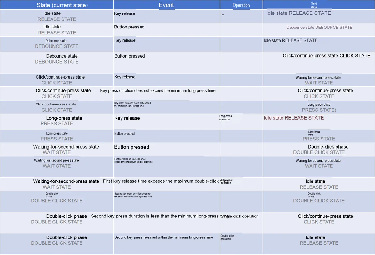
Furthermore, based on the current key event, the function will update the corresponding state variable (self.state). If the corresponding key operation (single click, double click, long press) is detected, the corresponding callback function will be executed.
It should be noted that there are the following three special cases:
- If a long press is performed within 500 ms after a short press, one single click and one long press operation will be triggered, and no double-click operation will be responded to.

- After performing consecutive short press operations with a time interval of less than 500 ms for an even number of 2n times, the system responds with n double-click operations.

- After performing consecutive short press operations for an odd number of times of 2n+ 1 with a time interval of less than 500ms, the response will be n times of double-click operations plus 1 time of single-click operation.

It is recommended here that after completing one operation (single-click, double-click, or long press), wait for 500ms before performing the next operation; otherwise, misoperation may occur.
3.1.2 Touch Key Detection Experiment
Here, we use capacitive touch buttons to implement the detection of single-click, double-click and long-press operations of the buttons.
The working principle of capacitive touch keys relies on changes in capacitance. Under constant surrounding environmental conditions, the capacitance between the key and the ground is a very small fixed value, and there is also capacitance between the human body and the ground. When a finger approaches the touch key, it is equivalent to connecting the capacitance between the human body and the ground in parallel with the capacitance between the touch key and the ground, thus increasing the total capacitance:
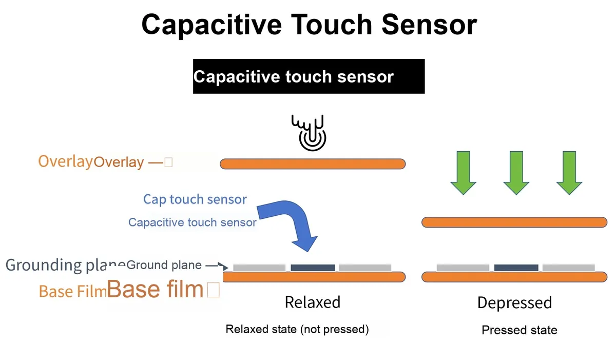
We usually connect a resistor in series with a power supply, and then connect this branch in parallel with the capacitive touch button. When the system is powered on, the power supply charges the capacitor. When a finger approaches the touch button, the total capacitance increases, which changes the RC time constant of the capacitor charging circuit. The state of the button can thus be detected by measuring the capacitor charging time.
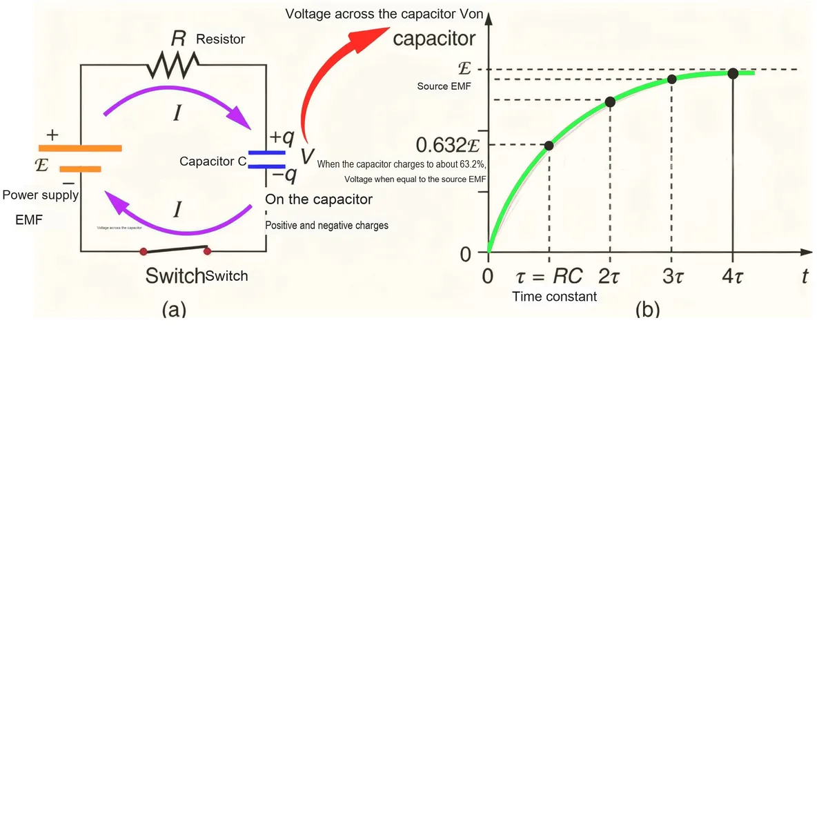
Here, we don’t need to measure the capacitor charging time via an analog-to-digital converter to determine whether a key is pressed; instead, we use a dedicated 4-channel touch key chip TTP224 to assist us with the judgment. TTP224 integrates internal components including a sensor oscillation circuit, timer, and touch detection circuit, which can directly output high and low levels after internal circuit processing once a capacitive key is pressed, allowing us to use capacitive touch keys just like mechanical keys.
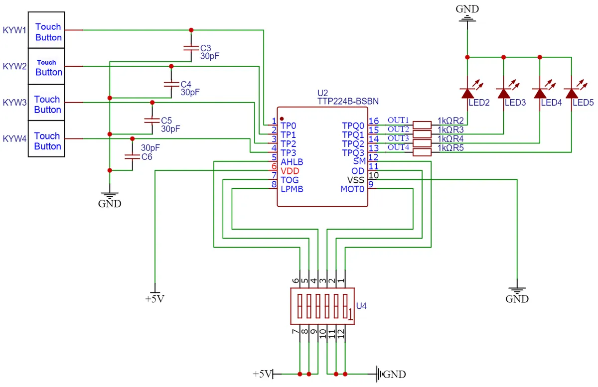
Here, in the 4-channel touch key module we designed, an LED is also connected to the OUT output terminal to indicate the key press status. When the capacitive key is not pressed, OUT the output terminal is at low level and the LED stays off; when the capacitive key is pressed, the OUT output terminal goes to high level and the LED lights up.
In the following experiment, we need to insert the Fengya No. 1 Board - Universal Compatible Expansion Board into the Fengya No. 1 Board - RGB Touch Expansion Board, and at the same time turn on all the options of the Fengya No. 1 Board - RGB Touch Expansion Board 's SWITCH1 DIP switch (TB_OUTx):
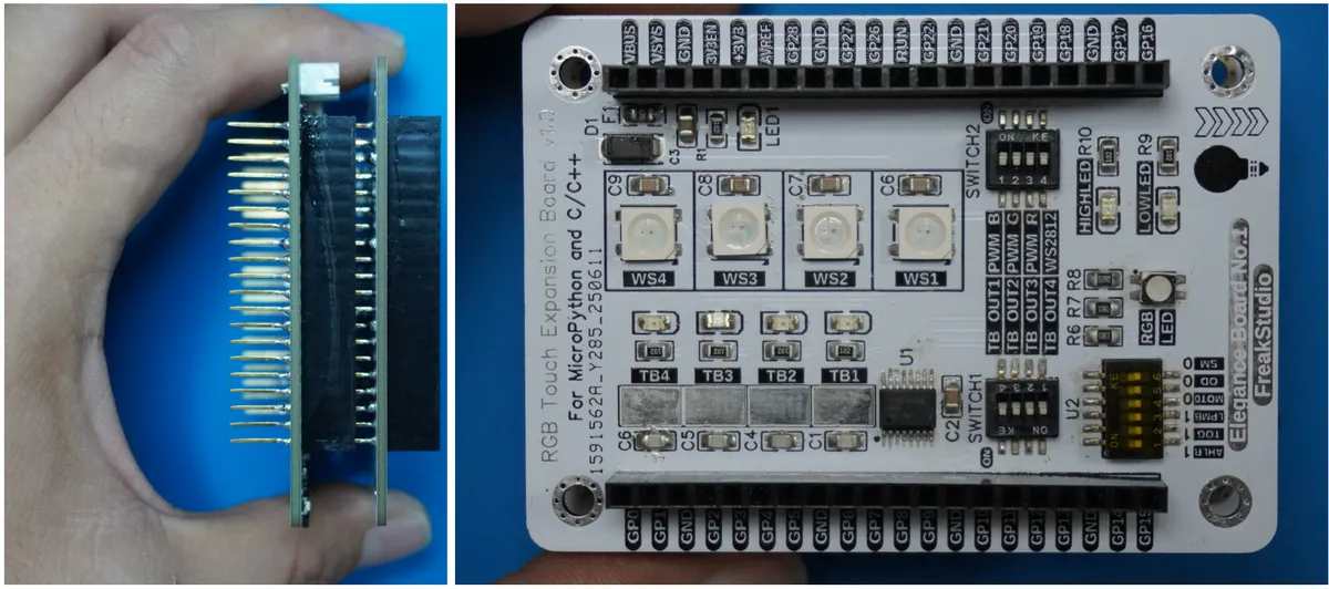
Here, the connection between the 4-channel touch key interface and the Raspberry Pi Pico is shown as follows:
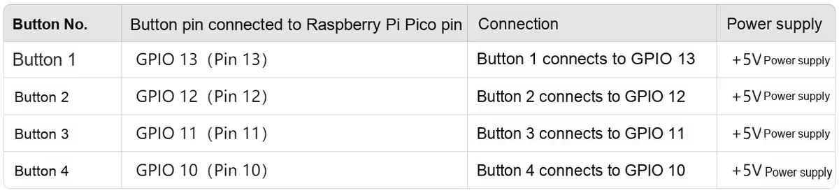
All the code for the experiments below is open-source and can be found in the material package we provide under the folder elegance-devkit v1\Demo\22 TIMER_ButtonFSM.
Next, let's start explaining the experimental code. First, we will put the framework of the key detection finite-state machine Button class code into the ButtonDetect.py file, and then in our main.py file, first import the necessary modules:
# Python env   : MicroPython v1.23.0
# -*- coding: utf-8 -*-
# @Time    : 2024/7/9 11:03 PM
# @Author  : Li Qingshui
# @File    : main.py
# @Description : Timer experiment, use a timer to implement short-press and long-press detection for a button

# ======================================== Import Modules ========================================

# Import hardware-related modules
from machine import Pin, Timer
# Import the button detection framework
from ButtonDetect import ButtonFSM
# Time-related modules
import time
Here, we define the callback function of the key after three different operations, and the callback function indicates the key operation and the key number:
# ======================================== Functions ============================================

# Button long-press callback function
def press_func(arg: int) -> None:
    """
    Button long-press callback function, triggered when the button is long-pressed.

    Args:
        arg (int): Button number or other identifying information.

    Returns:
        None: This function has no return value and only performs a print operation.
    """
    print('button %d is pressed' % arg)

# Button short-press callback function
def click_func(arg: int) -> None:
    """
    Button short-press callback function, triggered when the button is short-pressed.

    Args:
        arg (int): Button number or other identifying information.

    Returns:
        None: This function has no return value and only performs a print operation.
    """
    print('button %d is clicked' % arg)

# Button double-click callback function
def double_click_func(arg: int) -> None:
    """
    Button double-click callback function, triggered when the button is double-clicked.

    Args:
        arg (int): Button number or other identifying information.

    Returns:
        None: This function has no return value and only performs a print operation.
    """
    print('button %d is double clicked' % arg)
In the initialization configuration, we define the pins and timers used by the touch buttons, and create a Button instance:
# ======================================== Initialization ==========================================

# Delay to wait for the device to initialize
time.sleep(3)
# Print debug information
print("FreakStudio : Using ButtonFSM to detect the status of button")

# Define button pins
button_1_pin = Pin(10)
button_2_pin = Pin(11)
button_3_pin = Pin(12)
button_4_pin = Pin(13)

# Define timer object
timer_1 = Timer(-1)
timer_2 = Timer(-1)
timer_3 = Timer(-1)
timer_4 = Timer(-1)

# Create 4 button instances
button_1 = ButtonFSM(button_1_pin, timer_1, ButtonFSM.LOW, press_func, click_func, double_click_func,1)
button_2 = ButtonFSM(button_2_pin, timer_2, ButtonFSM.LOW, press_func, click_func, double_click_func,2)
button_3 = ButtonFSM(button_3_pin, timer_3, ButtonFSM.LOW, press_func, click_func, double_click_func,3)
button_4 = ButtonFSM(button_4_pin, timer_4, ButtonFSM.LOW, press_func, click_func, double_click_func,4)
Next, we create an infinite while loop, which is mainly to prevent the main.py file from exiting directly:
# ========================================  Main Program  ============================================

while True:
    pass
Burn the program, connect to the Raspberry Pi Pico via mpremote, and you can see the corresponding operation output in the terminal when pressing the button:
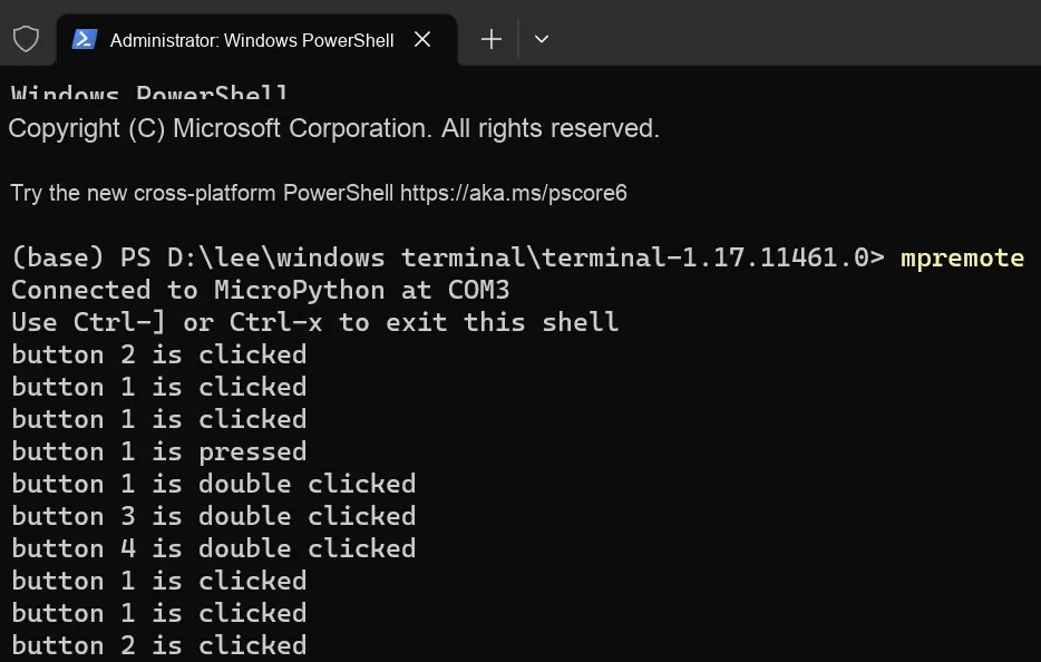
3.1 Application Experiment.mp4 46.1 MB
3.2 Implementing Task Scheduler with Timer
3.2.1 Basic Concepts and Characteristics of Task Scheduling
The biggest convenience of using timers is that they allow us to perform certain tasks at specific points in time or at regular time intervals, and we can regard them as an execution flow that is different from the while loop in the main program:
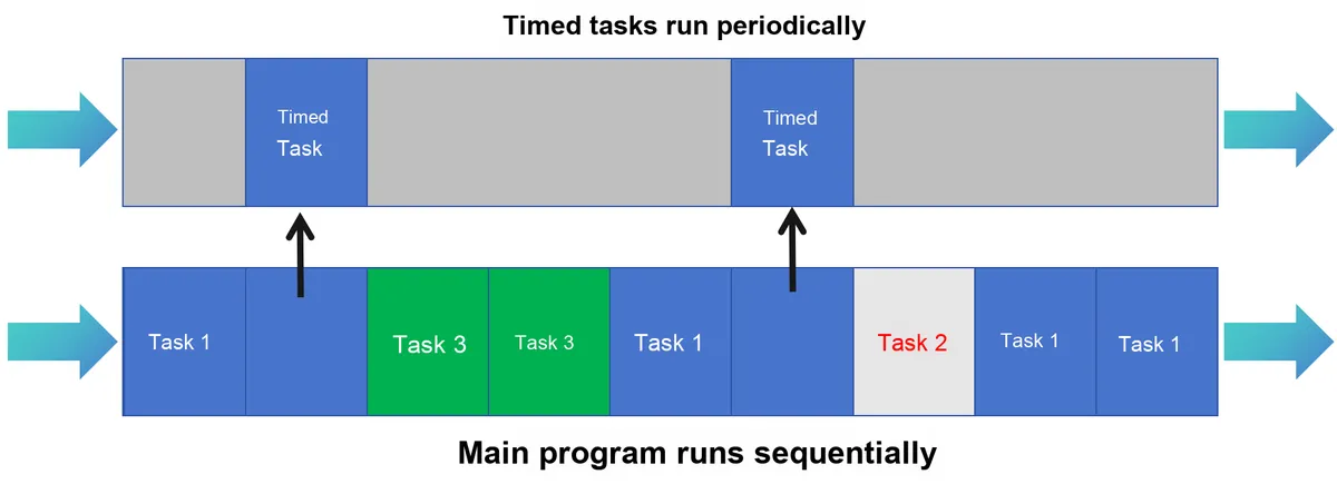
We can use the machine.Timer library to create timer objects, run timers once or periodically, execute callback functions and stop timers, which can be said to be very convenient.
Consider the following scenario:
- Task 1 is executed once every 500ms on a timed basis, and will no longer be executed 3000ms after the program starts running.
- Task 2 is executed once every 1000ms on a timed basis, pauses 3000ms after the program starts running, and resumes execution 7000ms after the program starts running
- Execute Task 3 regularly every 1000ms after 3000ms from the start of the program run
- Perform garbage collection when there are currently no tasks to execute.
If multiple timer objects are used, a large number of additional global variables and judgment conditions will be introduced, which will make the program complex and difficult to expand, for example:
- After Task 1 finishes running, we need to decide whether to start Task 3 based on the data obtained and the execution status of Task 1.
- Task 2 needs to have its periodic running time modified 7500 ms after the program starts running, and needs to be paused again 10000 ms after the program starts running
In this case, we can use a single timer to implement a task scheduler, which is a common programming pattern in embedded systems or real-time operating systems for managing and executing scheduled tasks.
Its main functions include:
- Task Management:
- Define the data structure of the task, including the task callback function, execution cycle, parameters, etc.
- Provides methods for adding, deleting, pausing and resuming tasks
- Maintain the task list and track the status and execution progress of tasks
- Task Scheduling:
- Determine which tasks need to be executed according to the task execution cycle and the current time
- Execute the callback function of the task and handle possible exceptions
Simply put, a task scheduler uses timers (such as hardware timers or software timers on microcontrollers) to periodically check the task list, determine which tasks need to be executed and which need to be suspended, and then perform corresponding operations.
3.2.2 Implementation of Custom Task Scheduling Class
Here, the routines reference code from the MicroPython Chinese Community, with some comments and minor modifications added on that basis:
micropython-simple-scheduler/tmScheduler/scheduler.py at main · micropython-Chinese-Community/microp
Here, in the Scheduler.py file, we first define a Task class, and the code is as follows:
# ======================================== Import Modules ========================================

# Import const constant identifier
from micropython import const
# Import hardware-related modules
from machine import Timer

# ======================================== Global Variables ============================================

# ======================================== Functions ============================================

# ======================================== Custom Classes ============================================

# Define Task class
class Task():
    """
    Task class, used to represent a task that runs on a timer, containing the task's callback function, parameters, execution interval and task state.

    This class allows a task to repeat at a set time interval, and supports pausing and resuming the task. It can be used to implement functions such as timed task scheduling.

    Attributes:
        TASK_RUN (int): Task running state identifier, value 0, indicating the task is running.
        TASK_STOP (int): Task stopped state identifier, value 1, indicating the task has stopped.
        _callback (callable): Callback function that executes the task, called when the task runs.
        _param (tuple): Parameters of the task callback function.
        _intv (int): Task execution interval in milliseconds, default 1000ms.
        _state (int): Task state, default TASK_RUN, indicating the task is running.
        _cnt (int): Task counter, indicating the number of times the task has executed, default 10.
        _rt (int): Return value of the task execution or other auxiliary information, default 0.

    Methods:
        __init__(self, callback, *param, interval=1000, state=TASK_RUN) -> None:
            Initialize a Task class instance, setting the callback function, parameters, interval and task state.

        pause(self) -> None:
            Pause the task, setting the task state to TASK_STOP.

        resume(self) -> None:
            Resume the task, setting the task state to TASK_RUN.

        run(self) -> None:
            Execute the task callback function, passing in the relevant parameters.
    """

    # Task state identifiers
    TASK_RUN  = const(0)
    TASK_STOP = const(1)

    def __init__(self, callback: callable, *param: object, interval: int = 1000, state: int = TASK_RUN) -> None:
        """
        Initialize a Task class instance, setting the callback function, parameters, execution interval and task state.

        Args:
            callback (callable): Callback function called when the task runs.
            *param (object): Parameters passed to the callback function.
            interval (int, optional): Task execution interval in milliseconds. Default is 1000ms.
            state (int, optional): Initial state of the task, default TASK_RUN, indicating the task is running.

        Returns:
            None
        """
        self._callback = callback
        self._param = param
        self._intv = interval
        self._state = state
        self._cnt = 10
        self._rt = 0

    def pause(self) -> None:
        """
        Pause the task, setting the task state to TASK_STOP.

        Args:
            None

        Returns:
            None
        """
        self._state = Task.TASK_STOP

    def resume(self) -> None:
        """
        Resume the task, setting the task state to TASK_RUN.

        Args:
            None

        Returns:
            None
        """
        self._state = Task.TASK_RUN

    def run(self) -> None:
        """
        Execute the task callback function, passing in the relevant parameters.

        Args:
            None

        Returns:
            None
        """
        self._callback(*self._param)
Task class represents a scheduled task, which includes attributes such as task callback function, parameters, execution interval and task status. It also provides methods for pausing the task, resuming the task and executing the callback function. The task status is represented by two constants: TASK_RUN and TASK_STOP.
Here, the core implementation principle of the pause method and resume method is to modify the status of the task instance. When the scheduler iterates through the status of each task instance in the task list, it will not execute the task if the task status is Task.TASK_STOP; otherwise, it will execute the task.
Then, we defined the Scheduler class for task scheduling, which is responsible for managing and executing all registered tasks.
# Define Scheduler class
class Scheduler():
    """
    Scheduler class, used to manage and schedule task execution.

    This class implements periodic task scheduling with a timer, and supports adding, deleting, pausing, resuming and executing tasks.
    A task can be any callable object. The scheduler periodically checks and executes tasks at the set time interval.
    In addition, the scheduler supports task idle and task error callback functions, used to handle special situations during task execution.

    Attributes:
        tm (machine.Timer): Timer instance, used to trigger task scheduling.
        interval (int): Timer interval in milliseconds.
        task_idle (callable): Callback function called when tasks are idle.
        task_err (callable): Callback function called when a task execution error occurs.
        tasks (list): Task list, storing all registered task instances.

    Methods:
        __init__(self, tm: Timer, interval: int = 100, task_idle: callable = None, task_err: callable = None):
            Initialize the scheduler instance, setting the timer, interval and callback functions.

        _tmrirq(self, t: Timer) -> None:
            Timer interrupt callback function, used to trigger task scheduling.

        _run(self, task: Task) -> None:
            Callback function that executes a single task.

        scheduler(self) -> None:
            Main loop of the scheduler, responsible for repeatedly executing all registered tasks.

        find(self, task: Task) -> int:
            Find the index of the specified task in the task list.

        clear(self) -> None:
            Clear the task list.

        add(self, task: Task, state: int = Task.TASK_RUN) -> None:
            Add a task to the task list.

        delete(self, task: Task) -> None:
            Delete the specified task from the task list.

        pause(self, task: Task) -> None:
            Pause execution of the specified task.

        resume(self, task: Task) -> None:
            Resume execution of the specified task.

        run(self, task: Task) -> None:
            Execute the callback function of the specified task.
    """

    def __init__(self, tm: Timer, interval: int = 100, task_idle: callable = None,
                 task_err: callable = None) -> None:
        """
        Initialize the scheduler class instance, setting the timer, timer interval, task idle callback function and task error callback function.

        Args:
            tm (machine.Timer): Timer instance, used to schedule tasks.
            interval (int, optional): Timer interval in milliseconds. Default is 100ms.
            task_idle (callable, optional): Callback function called when tasks are idle, default None.
            task_err (callable, optional): Callback function called when a task error occurs, default None.

        Returns:
            None
        """
        self._tasks     = []
        self._task_idle = task_idle
        self._task_err  = task_err
        self._interval  = interval
        self._tmr       = tm
        self._tmr.init(period=interval, callback=self._tmrirq)
During initialization, a timer instance (machine.Timer), timer interval, optional task idle callback function and task error callback function need to be passed in;_tmrirq () method is the timer interrupt callback function, which is used to traverse the task list and judge whether the task is running. If the task is still in the running state, the execution time interval of the task will be updated:
def _tmrirq(self, t: Timer) -> None:
    """
    Timer callback interrupt function, used to handle the timer interrupt.

    Args:
        t (machine.Timer): Timer instance that triggers the interrupt.

    Returns:
        None
    """
    # Traverse the task list
    for i in range(len(self._tasks)):
        # Check the task state
        if self._tasks[i]._state == Task.TASK_RUN:
            # Execution interval count of task _tasks[i] plus 1
            self._tasks[i]._rt += 1
_run () method is used to execute the callback function of a single task and handle any exceptions that may occur during task execution.
def _run(self, task: Task) -> None:
    """
    Execute a single task callback function.

    Args:
        task (Task): Task instance, containing the callback function to execute.

    Returns:
        None
    """
    # Check whether the task state is TASK_RUN
    if task._state == Task.TASK_RUN:
        try:
            # Check whether the task execution interval count is greater than or equal to the interval the task needs to execute at
            if task._rt >= task._cnt:
                # If so, execute the task callback function
                task._rt = 0
                task.run()
        except Exception as e:
            # If an exception occurs, execute the task error callback function
            if self._task_err:
                self._task_err(e)
The key method of the Scheduler class is scheduler (), which is an infinite loop responsible for continuously checking the status of tasks in the task list and performing corresponding operations according to the task status. Specifically, it will:
- Iterate through the task list, and for each task:
- If the task status is
Task.TASK_RUN, increase the execution time interval of the task; - If the execution time interval of the task reaches or exceeds the time interval required for the task to be executed, the callback function of the task will be executed, and the execution time interval will be reset to 0;
- If the task status is
- If all tasks are in the suspended state and there is an idle processing function, call this function;
- If any exception occurs, print the exception information and continue the execution.
def scheduler(self) -> None:
    """
    Main loop of the scheduler, responsible for repeatedly executing all registered tasks.

    Args:
        None

    Returns:
        None
    """

    # Poll the task states to decide whether to execute tasks
    while True:
        try:
            # Execute the tasks that have reached their execution interval
            for i in range(len(self._tasks)):
                task = self._tasks[i]
                self._run(task)
            # If idle, execute the task idle callback function
            if self._task_idle:
                self._task_idle()
        except KeyboardInterrupt:
            return
        # When an exception occurs, raise the exception location and type
        except Exception as e:
            print('except {}'.format(e))
Exception
Programs are fragile in most cases; only when all conditions meet the ideal state can the code consistently produce correct results. However, in practical applications, it cannot always be guaranteed that all computations will yield correct outcomes. An exception is an event that occurs during the execution of a program and disrupts its normal flow. Generally, an exception is raised when Python cannot handle a program properly.
In actual programming scenarios, most methods and constructors impose certain restrictions on the passed parameter values; for example, common index values must be non-negative, and object references cannot be null. You should mandatorily perform entry parameter checks at the beginning of a method, and if an illegal value is input, we can use the raise statement to trigger an exception by ourselves.
The syntax format of raise is as follows:
raise [Exception [, args [, traceback]]]
In the statement, Exception refers to the exception type (e. g., NameError), which can be any one of the standard exceptions; args denotes the user-provided exception parameters. The last parameter is optional (and rarely used in practice), and if present, it is the traceback exception object.
When an exception occurs in a Python script, we need to catch and handle it, otherwise the program will terminate execution. To catch exceptions, you can use the try/except statement, which is designed to detect errors in the try block, so that the except statement can capture the exception information and process it. If you don't want your program to terminate when an exception occurs, just catch it inside the try block. Below is the syntax for the simple try. ... except. .. else structure:
try:
<Sentence> </Sentence>
except <name>:
The working principle of the try statement is as follows:
- First, the try clause (the (multi-line) statement between the try and except keywords) is executed
- If no exception is triggered, the except clause is skipped, and the try statement completes execution.
- If an exception occurs while executing the try clause, the rest of the clause is skipped. If the exception type matches the exception specified after the except keyword, the except clause is executed, and execution then continues after the try/except Code Block
- If an exception that occurs does not match the exception specified in the except clause, it will be passed to the outer try statement; if no handler is found, it is an unhandled exception and execution will stop with an error message output.
Sometimes, when we catch an exception, we need to use a reference to the Exception object. This usually happens when we define our own exceptions with specific parameters, in which case we can use the as statement with the parameter as the exception information parameter for output.
In addition, the Scheduler class provides other methods, such as find () for finding the index of a task, clear () for clearing the task list, add () for adding a new task, delete () for deleting a task, pause () and resume () for pausing and resuming tasks, as well as run () for executing a task immediately.
def find(self, task: Task) -> int:
    """
    Find the index of the specified task in the task list.

    Args:
        task (Task): Task instance to find.

    Returns:
        int: Index of the task in the task list.
    """
    try:
        return self._tasks.index(task)
    except:
        return None

def clear(self) -> None:
    """
    Clear the task list.

    Args:
        None

    Returns:
        None
    """
    self._tasks.clear()

def add(self, task: Task, state: int = Task.TASK_RUN) -> None:
    """
    Add a task to the task list.

    Args:
        task (Task): Task instance, the task to add.
        state (int, optional): Task state, default Task.TASK_RUN, indicating the task is running.

    Returns:
        None
    """
    if self.find(task) == None:
        self._tasks.append(task)
        # task._cnt is the interval the task needs to execute at
        # Interval the task needs to execute at = task interval // timer interval
        task._cnt = task._intv // self._interval
        print('add task:', task._callback.__name__)
    if state == Task.TASK_STOP:
        self.pause(task)

def delete(self, task: Task) -> None:
    """
    Delete a task.

    Args:
        task (Task): Task instance, the task to delete.

    Returns:
        None
    """
    try:
        # Delete the specified task
        self._tasks.remove(task)
    except:
        print('del task <', task, '> error')

def pause(self, task: Task) -> None:
    """
    Pause a task.

    Args:
        task (Task): Task instance, the task to pause.

    Returns:
        None
    """
    if self.find(task) != None:
        self._tasks[self.find(task)].pause()

def resume(self, task: Task) -> None:
    """
    Resume a task.

    Args:
        task (Task): Task instance, the task to resume.

    Returns:
        None
    """
    if self.find(task) != None:
        self._tasks[self.find(task)].resume()

def run(self, task: Task) -> None:
    """
    Execute the task callback function.

    Args:
        task (Task): Task instance, containing the callback function to execute.

    Returns:
        None
    """
    if self.find(task) != None:
        task._rt = task._cnt
        self._run(task)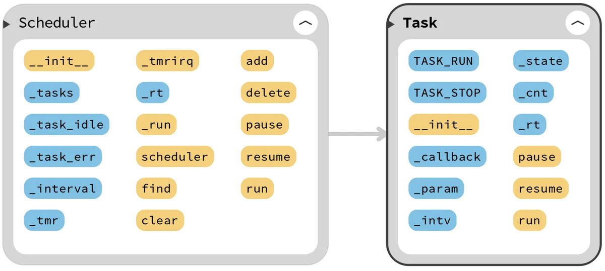
3.2.3 Task Scheduling Application Experiment
All the code for the following experiments is open-source in the resource package we provide, and can be found in the elegance-devkit v1\Demo\23 TIMER_Scheduler folder.
Next, we will implement our sample program in main.py, starting by importing the relevant modules:
# Python env   : MicroPython v1.23.0
# -*- coding: utf-8 -*-
# @Time    : 2024/7/11 9:43 AM
# @Author  : Li Qingshui
# @File    : main.py
# @Description : Timer class experiment, using a timer to schedule tasks
# Code reference: https://github.com/micropython-Chinese-Community/micropython-simple-scheduler/tree/main

# ======================================== Import Modules ========================================

# Import hardware-related modules
from machine import Timer
# Import the task scheduler
from Scheduler import Scheduler, Task
# Import the time module
import time
# Garbage collection module
import gc
# Import system-related modules
import sys
Then define some variables: the global variable time_start is used to record the task start time, and RunCnt is used to record the execution count of the callback function:
# ======================================== Global Variables ============================================

# Task start time
time_start = time.ticks_us()
# Method execution count
RunCnt = 0
Then define a timing decorator function to measure the running time of the program:
# Timing decorator, used to measure function run time
def timed_function(f: callable, *args: tuple, **kwargs: dict) -> callable:
    """
    Timing decorator, used to measure and print function/method run time.

    Args:
        f (callable): The function/method to be passed in
        args (tuple): Any number of positional arguments passed to function/method f
        kwargs (dict): Any number of keyword arguments passed to function/method f

    Returns:
        callable: Returns the timed function
    """
    myname = str(f).split(' ')[1]

    def new_func(*args: tuple, **kwargs: dict) -> any:
        t: int = time.ticks_us()
        result = f(*args, **kwargs)
        delta: int = time.ticks_diff(time.ticks_us(), t)
        print('Function {} Time = {:6.3f}ms'.format(myname, delta / 1000))
        return result

    return new_func
Then we define task_callback task callback function, which is used to perform specific operations when each task is executed, and this function accepts one parameter task_id that represents the ID of the current task. The main execution logic of this function is as follows:
- Calculate the time difference from the task start time to the current time and convert it into milliseconds
- Output the number of task runs, task running time and task ID
- Increment the task run count by 1
- Perform different operations according to the number of task runs:
- If the task has run 5 times, pause Task 2, create a new Task 3 (which executes once every 1000 milliseconds), add it to the scheduler, and delete Task 1
- If the task has run 8 times, resume Task 2
# Use the @timed_function decorator to measure task run time
@timed_function
def task_callback(task_id: int) -> None:
    """
    Task callback function, used to print task information and manage task state.

    Args:
        task_id (int): Task ID, used to identify the current task.

    Returns:
        None
    """
    global time_start, RunCnt, sc, task1, task2
    # Calculate the time difference from the start time to now
    time_now = (time.ticks_us() - time_start) / 1000

    # Output the task run count, task run time and task ID
    print('{} - {:.2f} ms: task {} is running'.format(RunCnt, time_now, task_id))

    # Increment the task run count by 1
    RunCnt = RunCnt + 1

    # Check the task run count
    if RunCnt == 5 :
        # Pause task 2
        sc.pause(task2)
        print('pause task 2')
        # Create task 3, executed every 1000ms
        task3 = Task(task_callback, 3, interval=1000, state=Task.TASK_RUN)
        # Add task 3
        sc.add(task3)
        print('add task 3')
        # Delete task 1
        sc.delete(task1)
        print('delete task 1')

    # Check the task run count
    if RunCnt == 8:
        # Resume task 2
        sc.resume(task2)
Then two callback functions are defined: task_idle_callback () and task_err_callback ():
- Idle Task Callback function: The task_idle_callback function is invoked when there are no tasks to be executed in the scheduler. Inside this function, it first checks whether the number of bytes of currently available heap RAM is less than 230000. If so, it indicates that the memory may be insufficient, so the garbage collection function (gc.collect ()) is manually triggered to release memory that is no longer in use. The function serves to help the system perform self-optimization when memory is tight.
- Exception callback function: The task_err_callback function is invoked when an exception occurs during task execution. Inside this function, sys.print_exception (e) is used to print the detailed information of the exception. After that, the function enters an infinite loop, continuously printing "task run error" so that the problem can be detected and handled in a timely manner when an exception arises. This function serves to provide error handling and debugging information when a task execution error occurs.
# Idle task callback function
def task_idle_callback() -> None:
    """
    Idle task callback function, used to manually trigger garbage collection when memory is low.

    Args:
        None

    Returns:
        None
    """
    # When the available heap RAM is less than 230000 bytes, manually trigger garbage collection
    if gc.mem_free() < 230000:
        # Manually trigger garbage collection
        gc.collect()

# Exception callback function
def task_err_callback(e: Exception) -> None:
    """
    Exception callback function, used to print exception information and handle task errors.

    Args:
        e (Exception): The caught exception object.

    Returns:
        None
    """
    while True:
        sys.print_exception(e)
        print('task run error')
Next, we create a task and a scheduler, add the task to the scheduler, and then start task scheduling:
# ======================================== Initialization ==========================================

# Power-on delay of 3 s
time.sleep(3)
# Print debug information
print("FreakStudio : Using Timer to implement a simple task scheduler")

# Create task 1, executed every 500ms
task1 = Task(task_callback, 1, interval=500, state=Task.TASK_RUN)
# Create task 2, executed every 1000ms
task2 = Task(task_callback, 2, interval=1000, state=Task.TASK_RUN)

# Create the task scheduler with a timer period of 100ms
sc = Scheduler(Timer(-1), interval=100, task_idle=task_idle_callback, task_err=task_err_callback)

# Add tasks
sc.add(task1)
sc.add(task2)

# ========================================  Main Program  ============================================

# Delay 2s, wait for the program to finish flashing before opening the terminal
time.sleep(2)
# Start scheduling
sc.scheduler()
Burn the code, and then open the terminal, where you can see the tasks running in the set order:
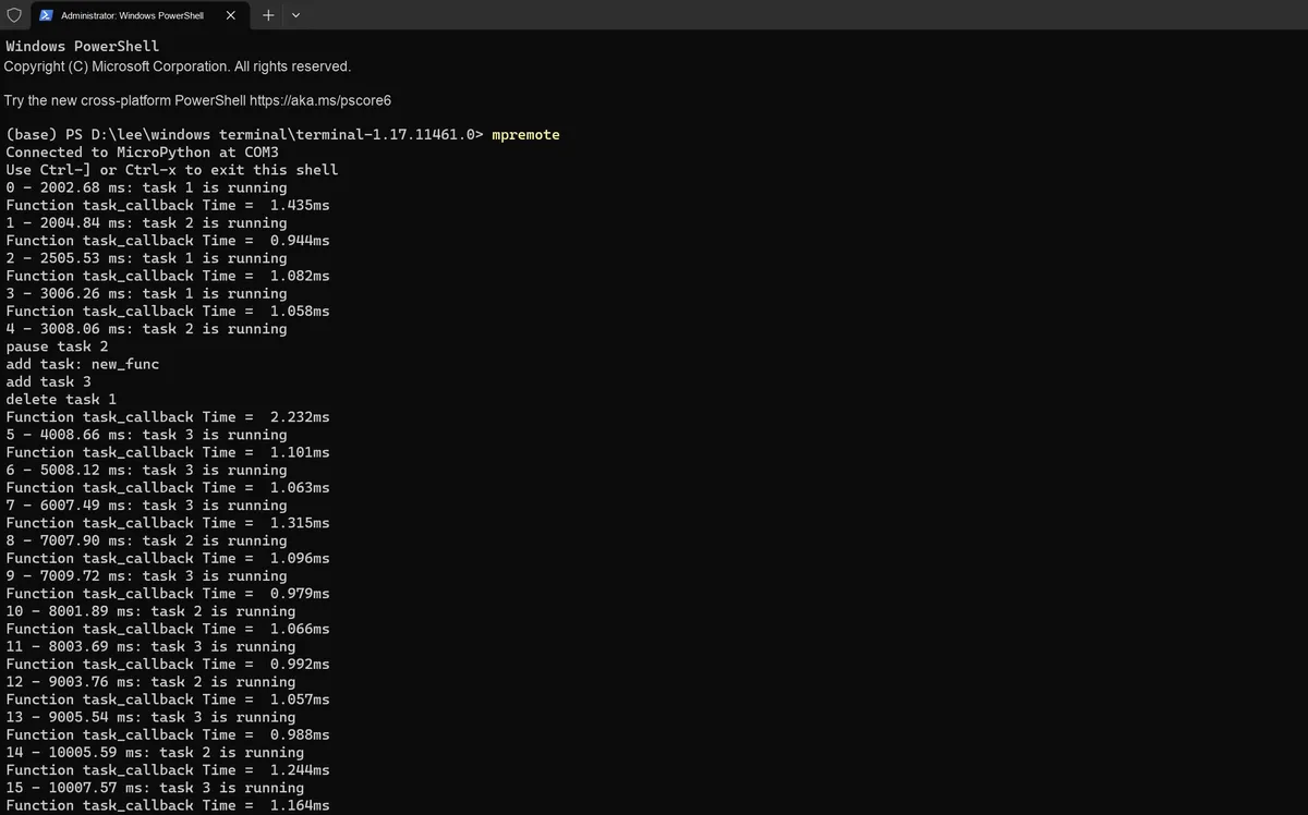
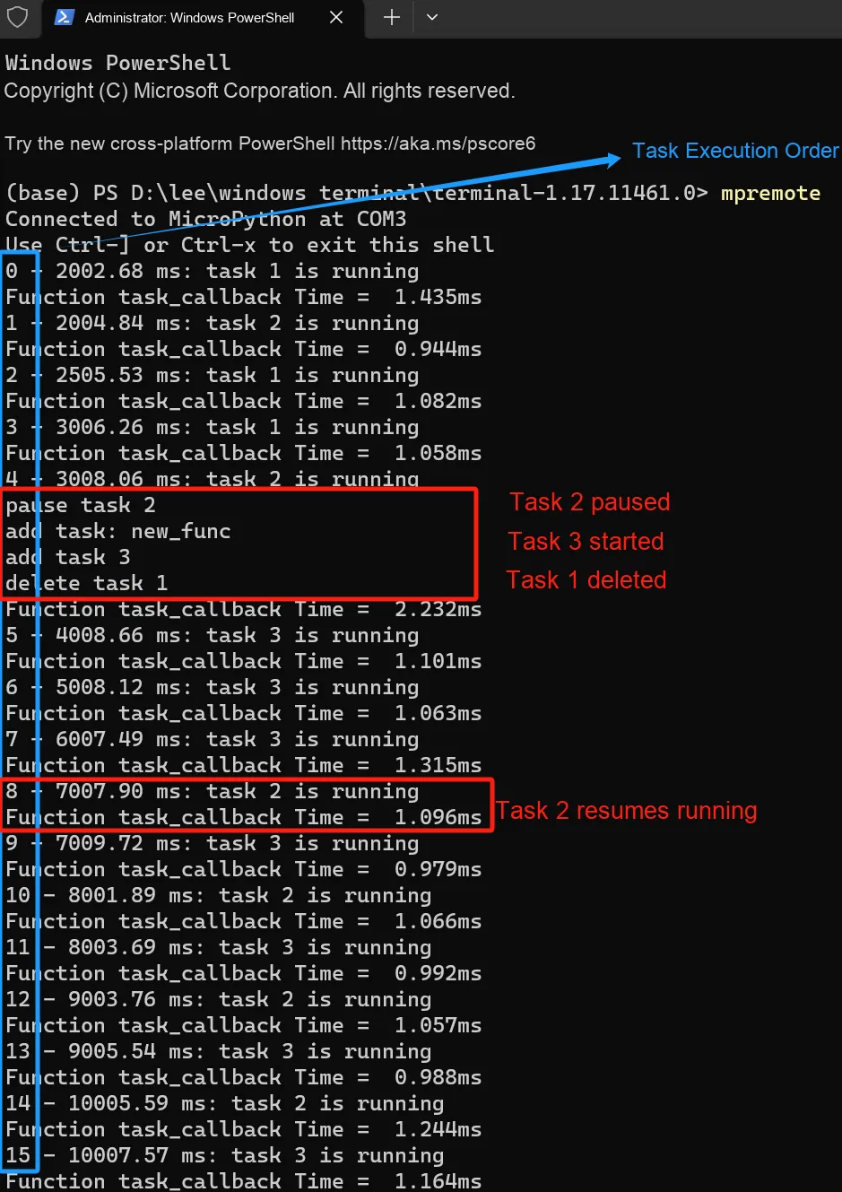
3.2 Application Experiment.mp4 5.5 MB
The execution Sequence Diagram of Task 1, Task 2, Task 3 and the idle task is as follows:
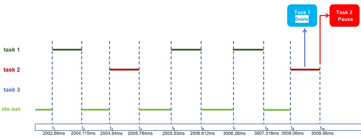
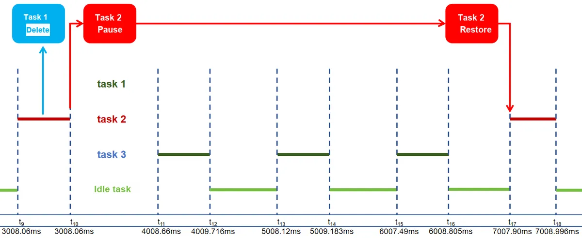
3.3 Timer Reads the Status of the Rotary Encoder
Here, we need to insert the Fengya No. 1 Board - Universal Compatible Expansion Board into the Fengya No. 1 Board - LCD Screen Human-Machine Interaction Board, and turn on the RE-CLK, RE-DT, and RE-SW on the DIP switch SWITCH2. The physical connection diagram is shown below:
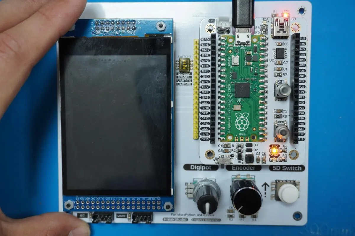
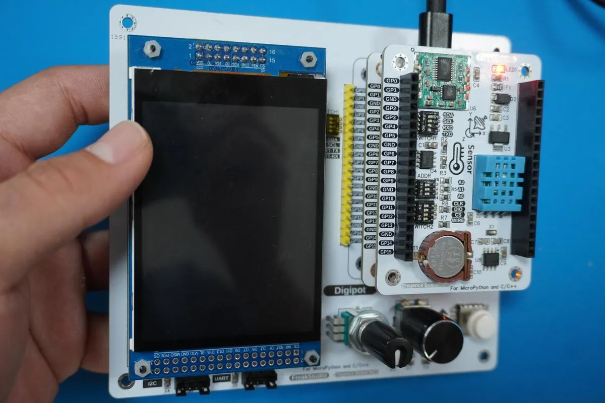
The wiring conditions of the components are as follows:
EC11 Pin Functions | Raspberry Pi Pico Pins | Description |
VCC (+3.3V) |
| Power supply voltage, connected to the 3.3V power output of the Pico |
GND |
| common ground |
Phase A |
| Encoder rotation signal A, for phase detection |
Phase B |
| Encoder rotation signal B, for phase detection |
Pushbutton SW |
| Encoder pushbutton switch, outputs low level when pressed |
All the code for the following experiments is open-source in the resource package we provide, which can be found in the elegance-devkit v1\Demo\24 TIMER_RotaryEncoder folder.
Previously, we mentioned in the GPIO experiment that the count value of the rotary encoder sometimes jumps by several units with each single rotation. This is mainly because the rotary encoder is a mechanical device: when the user rotates it, the contact points will repeatedly make and break contact within a short period, causing signal jitter and thus generating redundant counting pulses.
In the following code, we use a software timer to implement debouncing for the rotary encoder: we judge the encoder signals collected multiple times within a short period, and only consider the signal valid when the same encoder signal is detected for several consecutive times. The code is shown as follows:
# Python env   : MicroPython v1.23.0
# -*- coding: utf-8 -*-
# @Time    : 2024/9/19 7:46 PM
# @Author  : Li Qingshui
# @File    : main.py
# @Description : Timer class experiment, read the value of a rotary encoder and use a timer for software debouncing

# ======================================== Import Modules =========================================

# Import hardware-related modules
from machine import Pin, Timer
# Import time-related modules
import time

# ======================================== Global Variables ============================================

# ======================================== Functions ============================================

# ======================================== Custom Classes ============================================

# EC11 rotary encoder class
class EC11Encoder:
    """
    EC11Encoder class, used to process the signals of an EC11 rotary encoder.

    This class reads the A-phase signal, B-phase signal and button signal of the rotary encoder through GPIO pins, and supports detecting the rotation direction and determining the button state.
    Debouncing ensures signal stability, and the class provides queries for the rotation count and the button state.

    Attributes:
        pin_a (Pin): GPIO pin instance for the A-phase signal.
        pin_b (Pin): GPIO pin instance for the B-phase signal.
        pin_btn (Pin): GPIO pin instance for the button signal.
        rotation_count (int): Rotation counter that records the number of rotation steps (positive means clockwise, negative means counterclockwise).
        button_pressed (bool): Button state, True means the button is pressed, False means the button is not pressed.
        debounce_timer_a (Timer): Debounce timer instance for the A-phase signal.
        debounce_timer_btn (Timer): Debounce timer instance for the button signal.
        debouncing_a (bool): Debouncing state flag of the A-phase signal.
        debouncing_btn (bool): Debouncing state flag of the button signal.
    """

    def __init__(self, pin_a: int, pin_b: int, pin_btn: int) -> None:
        """
        Initialize the EC11 rotary encoder class.

        Args:
            pin_a (int): GPIO pin number for the A-phase signal.
            pin_b (int): GPIO pin number for the B-phase signal.
            pin_btn (int): GPIO pin number for the button signal.
        """
        # Initialize the GPIO pins of phase A and phase B, set to input mode
        self.pin_a = Pin(pin_a, Pin.IN)
        self.pin_b = Pin(pin_b, Pin.IN)
        # Initialize the button pin, set to input mode, and enable the internal pull-up resistor
        self.pin_btn = Pin(pin_btn, Pin.IN, Pin.PULL_UP)

        # Initialize the counter used to record the number of rotation steps
        self.rotation_count = 0
        # Button state, used to record whether the button is pressed
        self.button_pressed = False

        # Debounce related: timers
        # A-phase debounce timer
        self.debounce_timer_a   = Timer(-1)
        # Button debounce timer
        self.debounce_timer_btn = Timer(-1)

        # Flag indicating whether debouncing is in progress
        # A-phase debounce flag
        self.debouncing_a = False
        # Button debounce flag
        self.debouncing_btn = False

        # Set up interrupt handling for the A-phase pin, detect only the rising edge (to avoid duplicate counting)
        self.pin_a.irq(trigger=Pin.IRQ_RISING, handler=self._handle_rotation)
        # Set up interrupt handling for the button pin, detect button press (falling edge) and release (rising edge)
        self.pin_btn.irq(trigger=Pin.IRQ_FALLING | Pin.IRQ_RISING, handler=self._handle_button)

    def _handle_rotation(self, pin: Pin) -> None:
        """
        Interrupt callback function, used to detect the rising edge of the A phase and determine the direction based on the B-phase state.

        Args:
            pin (Pin): A-phase signal pin instance that triggered the interrupt.

        Returns:
            None
        """
        # If debouncing is in progress, return directly
        if self.debouncing_a:
            return

        # Start the debounce timer, run the check after a 1ms delay
        self.debouncing_a = True
        self.debounce_timer_a.init(mode=Timer.ONE_SHOT, period=1, callback=self._check_debounce_a)

    def _check_debounce_a(self, t: Timer) -> None:
        """
        Debounce timer callback function, used to detect whether the A phase is stable at a high level.

        Args:
            t (Timer): Timer instance that triggered the callback.

        Returns:
            None
        """
        # After 1ms the A phase is still high, confirmed as valid
        if self.pin_a.value() == 1:
            # Get the current state of the B phase (high or low level)
            current_state_b = self.pin_b.value()

            # On the A-phase rising edge, check the B-phase state to determine the rotation direction
            if current_state_b == 0:
                # Clockwise rotation, counter increases by 1
                self.rotation_count += 1
            else:
                # Counterclockwise rotation, counter decreases by 1
                self.rotation_count -= 1

        # Reset the debouncing state
        self.debouncing_a = False

    def _handle_button(self, pin: Pin) -> None:
        """
        Interrupt callback function, used to detect button press and release.

        Args:
            pin (Pin): Button pin instance that triggered the interrupt.

        Returns:
            None
        """
        # If debouncing is in progress, return directly
        if self.debouncing_btn:
            return

        # Start the debounce timer, run the check after a 5ms delay
        self.debouncing_btn = True
        self.debounce_timer_btn.init(mode=Timer.ONE_SHOT, period=5, callback=self._check_debounce_btn)

    def _check_debounce_btn(self, t: Timer) -> None:
        """
        Button debounce timer callback function, used to detect whether the button is stable.

        Args:
            t (Timer): Timer instance that triggered the callback.

        Returns:
            None
        """
        if self.pin_btn.value() == 0:
            # Button pressed, update the state
            self.button_pressed = True
        else:
            # Button released, update the state
            self.button_pressed = False

        # Reset the rotary encoder count value to zero
        self.reset_rotation_count()
        # Reset the debouncing state
        self.debouncing_btn = False

    def get_rotation_count(self) -> int:
        """
        Get the total number of rotations (positive means clockwise, negative means counterclockwise).

        Args:
            None

        Returns:
            int: Current rotation count value.
        """
        return self.rotation_count

    def reset_rotation_count(self) -> None:
        """
        Reset the rotation counter, clearing the number of rotation steps to zero.

        Args:
            None

        Returns:
            None
        """
        self.rotation_count = 0

    def is_button_pressed(self) -> bool:
        """
        Return whether the button is pressed.

        Args:
            None

        Returns:
            bool: True means the button is pressed, False means the button is not pressed.
        """
        return self.button_pressed

# Terminal progress bar class
class ProgressBar:
    """
    Terminal progress bar class, used to display an updatable progress bar in the terminal.

    This class shows the progress of the current task by drawing a progress bar in the terminal. It supports dynamic updates of the progress bar and allows the user to
    customize the maximum value and the length of the bar. The bar uses green for the completed part and red for the remaining part.

    Attributes:
        max_value (int): Maximum value of the progress bar, representing the total progress of the task. When the current progress reaches this value, the bar shows 100%.
        bar_length (int): Total length of the progress bar, used to control its width. Defaults to 50.

    Methods:
        update(current_value: int) -> None: Updates the progress bar display; takes the current progress value.
        reset() -> None: Resets the progress bar to 0%, showing an all-red bar.
    """

    def __init__(self, max_value: int, bar_length: int = 50) -> None:
        """
        Initialize the progress bar.

        Args:
            max_value (int): Maximum value of the progress bar. The bar shows 100% when this value is reached.
            bar_length (int): Total length of the progress bar. Defaults to 50.
        """
        self.max_value = max_value
        self.bar_length = bar_length

    def update(self, current_value: int) -> None:
        """
        Update the progress bar.

        Calculates and updates the progress bar display based on the current value, ensuring the current value does not exceed the maximum value.

        Args:
            current_value (int): Current value of the progress bar.
        """
        if current_value > self.max_value:
            current_value = self.max_value
        if current_value < 0:
            current_value = 0

        progress = current_value / self.max_value
        block = int(self.bar_length * progress)

        # Green indicates progress, red indicates the remainder
        bar = '\033[92m' + '█' * block + '\033[91m' + '-' * (self.bar_length - block) + '\033[0m'
        print(f"\r[{bar}]", end='')

    def reset(self) -> None:
        """
        Reset the progress bar.

        Resets the progress bar to 0%, i.e. all red.
        """
        print(f"\r\033[91m[{'-' * self.bar_length}]\033[0m", end='')

# ======================================== Initialization ==========================================

# Power-on delay of 3 s
time.sleep(3)
# Print debug information
print("FreakStudio : Using GPIO read Rotary Encoder value, use software debounce by timer")

# Create an EC11 rotary encoder object, using GPIO26 and GPIO27 as phase A and phase B, and GPIO28 as the button
# If you want to change the rotation direction in which the encoder count increases (for example, from counterclockwise increasing to clockwise increasing)
# just swap the values of the pin_a and pin_b parameters when initializing the encoder object
encoder = EC11Encoder(pin_a=26, pin_b=27, pin_btn=28)
# Create the terminal progress bar object to display progress; 20 rotations reach 100%
progress_bar = ProgressBar(max_value=20)

# ========================================  Main Program  ===========================================

# Get the rotation count and button state in the main loop
while True:
    # Get the rotation count
    current_rotation = encoder.get_rotation_count()
    print(f"Rotation count: {current_rotation}")
    # Update the progress bar
    progress_bar.update(current_rotation)
    # When the button is pressed, reset the progress bar
    if encoder.is_button_pressed():
        progress_bar.reset()
    # Update every 10ms
    time.sleep_ms(10)
The basic logic of timer-based debouncing is as follows:
- Rotary Encoder Debouncing: When triggered by the rising edge of Phase A, the rotation count value will not be adjusted immediately; instead, a 1ms one-shot timer is started. After 1ms, check whether Phase A is still at high level: if it is, the current trigger is valid; otherwise, it is regarded as jitter and the current trigger will be ignored.
- Key debouncing: When the key state changes (pressed or released), start a timer, wait for 5ms before checking the key state to ensure the key is stably at low or high level, then update the key state
Meanwhile, we define debounce_timer_btn and debouncing_btn debounce flags. After an interrupt is triggered, the interrupt callback function will not be executed again during the callback period of the first interrupt trigger, so as to prevent repeated interrupt triggering during the debounce period.
Burn the code, open the terminal, and the output is as follows:
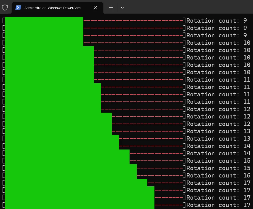
It can be seen that when we rotate the encoder this time, there is no longer the inaccuracy of the rotation counter caused by jitter as before.
3.3 Application Experiment.mp4 47.0 MB
3.5 PWM Signal Control for LED Breathing Light
All codes for the following experiments are open-source and can be found in the material package we provide, under the folder elegance-devkit v1\Demo\26 PWM_LED.
Here, we use PWM signals to control the onboard LED breathing lamp and print the PWM duty cycle. The code is as follows:
# Python env   : MicroPython v1.23.0
# -*- coding: utf-8 -*-
# @Time    : 2024/7/10 10:42 PM
# @Author  : Li Qingshui
# @File    : main.py
# @Description : PWM timer experiment, use PWM to implement a breathing light

# ======================================== Import Modules ========================================

# Import hardware-related modules
from machine import Pin, PWM, Timer
# Import time-related modules
import time

# ======================================== Global Variables ============================================

# PWM duty cycle parameter coefficient
pwm_duty = 0
# Duty cycle
value    = 0

# ======================================== Functions ============================================

def breathing(t:Timer) -> None:
    '''
    Breathing light function, implements the LED breathing effect by periodically adjusting the PWM duty cycle.

    This function is called periodically by a timer and dynamically adjusts the PWM duty cycle so that the LED brightness goes from dim to bright and back to dim, forming a breathing effect.

    Args:
        t (machine.Timer): Timer instance used to trigger the breathing light effect.

    Returns:
        None
    '''
    # Declare global variables
    global pwm_duty,value,LED

    # Adjust the LED duty cycle, the duty cycle is value / 65535
    value = int(abs(32000- pwm_duty*1000))
    LED.duty_u16(value)

    # Calculate the next duty cycle from the current duty cycle
    pwm_duty = (pwm_duty + 1) % 64

    # Print the PWM duty cycle
    print('PWM duty :', LED.duty_u16() / 65535)

# ======================================== Custom Classes ============================================

# ======================================== Initialization ==========================================

# Power-on delay of 3 s
time.sleep(3)
# Print debug information
print('FreakStudio:Using PWM to control LED')

# Configure the breathing LED pin
LED = PWM(Pin(25), freq=100, duty_u16=0)

# Create a timer object
timer = Timer(-1)
# Timer initialization: periodic mode, callback function is breathing, executed once every 100ms
timer.init(period=100, mode=Timer.PERIODIC, callback=breathing)

# ========================================  Main Program  ============================================

# Main program
while True:
    pass
As you can see, we use a timer to call the breathing function every 100ms, and this function continuously adjusts the duty cycle of the LED to achieve the breathing light effect. It should be noted here that we have declared a global variable in the breathing method to ensure normal operation:
# Declare global variables
global pwm_duty,value,LED
global keyword
The global keyword is used because Python is a dynamically typed language, where variables can be reassigned inside a function without prior type declaration. Without the global keyword, operations on a variable inside a function will create a new local variable instead of modifying the global one. This may lead to unexpected behavior, such as modifying a global variable inside a function only to find that the variable remains unchanged outside the function.
Using the global keyword can explicitly tell the Python interpreter that what we want to access inside the function is a global variable rather than creating a new local variable. This can avoid potential errors and ensure the readability and maintainability of the code.
After burning the code, we can see that the LED realizes the breathing light effect, gradually dimming from bright to dark and then brightening from dark to bright:
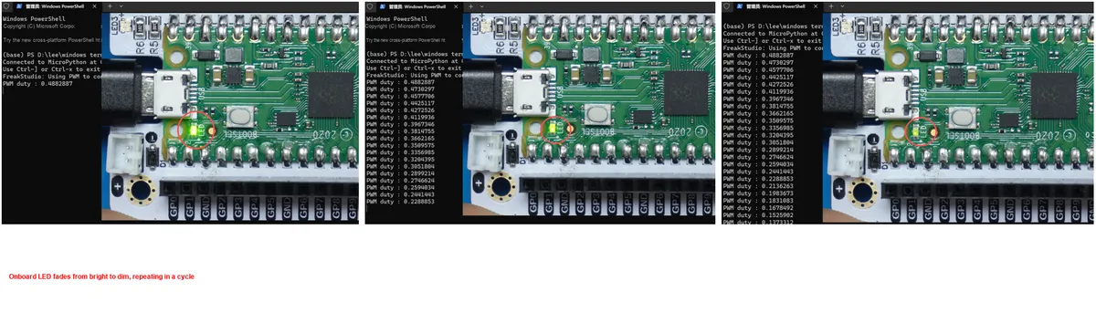
Meanwhile, the terminal outputs the data of the PWM duty cycle:
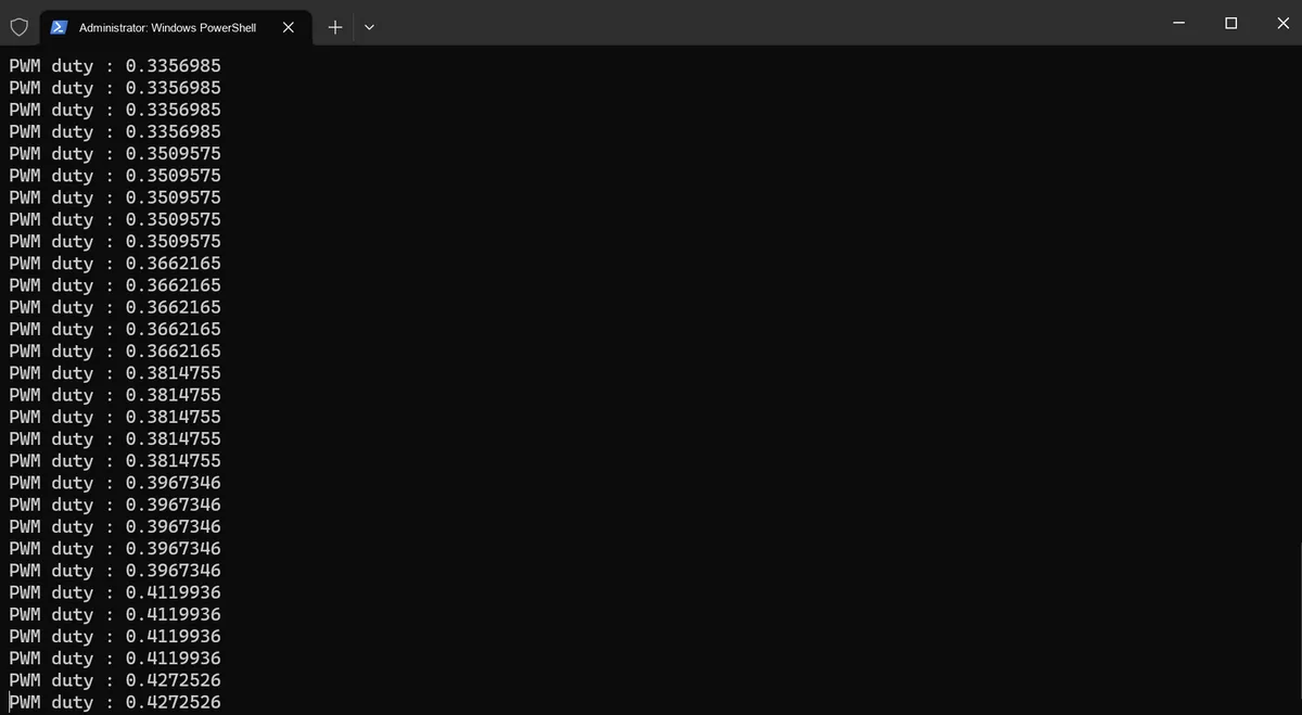
3.5 Application Experiment.mp4 72.6 MB
3.6 PWM Signal Control of RGB LED
3.6.1 Basics of RGB LED
An RGB LED (Red, Green, Blue Light-Emitting Diode) is a light-emitting device composed of three LEDs of different colors: red, green and blue. By adjusting the brightness of these three colors, it can generate light of various colors; RGB LEDs are widely used in scenarios such as display screens, decorative lighting and indicator lights.
An RGB LED typically integrates three independent LED chips, each responsible for emitting light of one of the three primary colors: red, green and blue. These chips can be controlled independently, so a wide range of colors can be mixed by combining different brightness levels: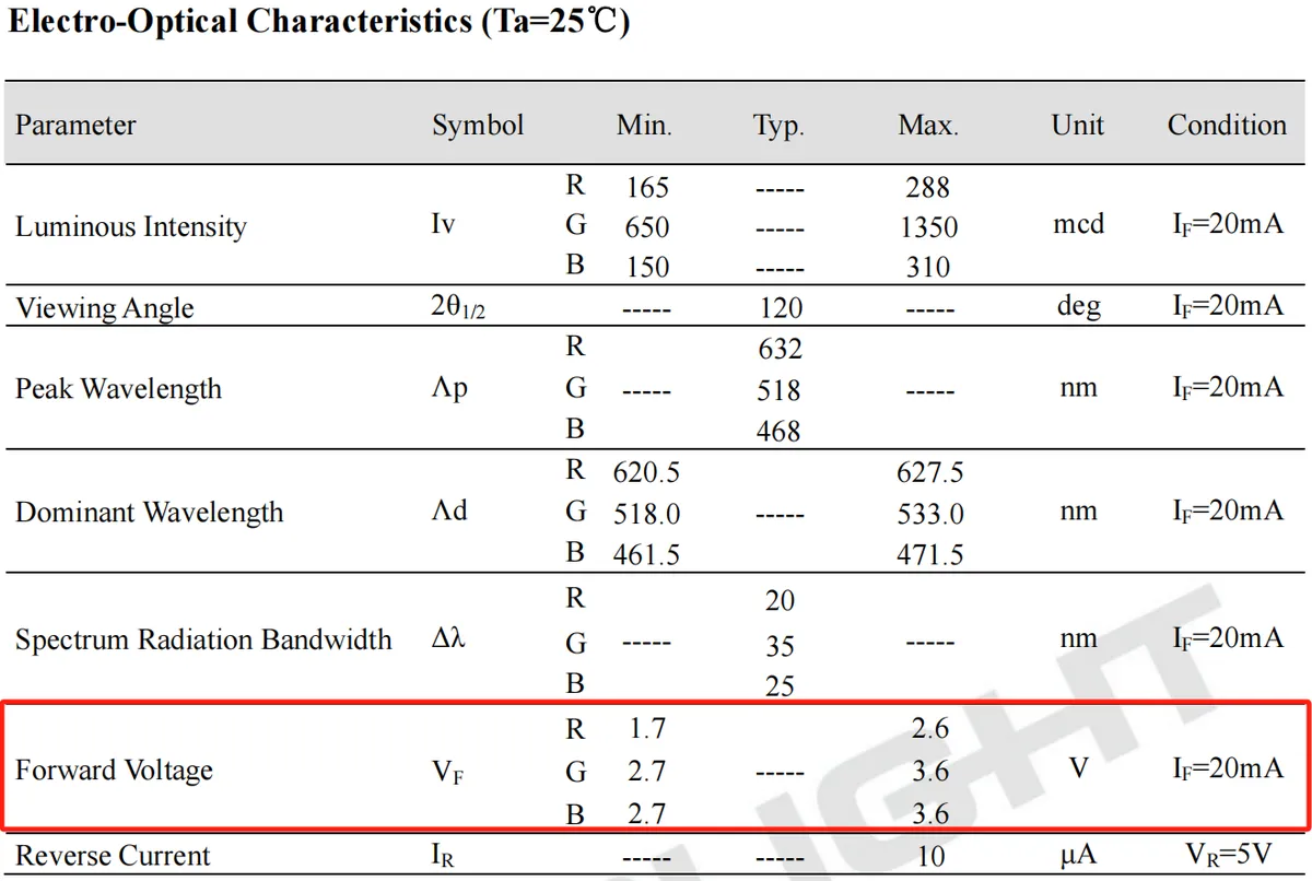
- Red (R): Emits red light and typically operates at a relatively low voltage
- Green (G): Emits green light, with a medium operating voltage
- Blue (B): Emits blue light and typically operates at a relatively high voltage
An RGB LED can generate various colors by mixing red, green and blue light. We can use Pulse Width Modulation (PWM) to precisely control the brightness of each LED, and the brightness of each color can be adjusted by changing the duty cycle of the voltage (0~100%), thus realizing rich color variations.
RGB LEDs can be divided into the following two types according to their structure: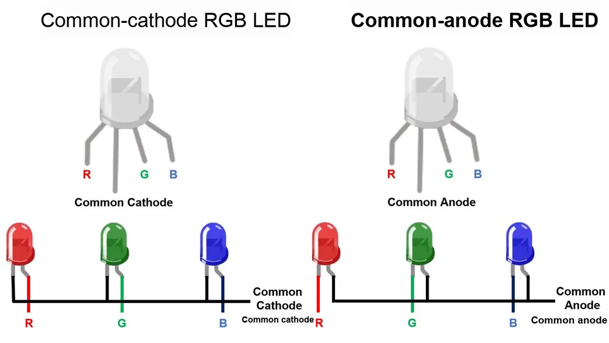
- Common cathode: The cathodes of all LEDs are connected together, and their anodes are respectively connected to different control terminals of the circuit
- Common Anode: The anodes of all LEDs are connected together, and their cathodes are respectively connected to different control terminals of the circuit
The parameters of an RGB LED reflect its electrical and optical properties, which not only determine the luminous efficacy, color and brightness of the LED, but also affect its application in circuits:
- Forward Voltage (VF): Forward voltage refers to the voltage difference between the two electrodes when an LED is forward conducting; LEDs of different colors have varying operating voltage ranges due to differences in their materials.
- Maximum Forward Current (IF): The maximum forward current refers to the maximum current allowed to pass through an LED during normal operation, with a common value of 20mA; exceeding this current may damage the LED, cause overheating, or shorten the LED's service life.
- Luminous Intensity (Iv): Luminous intensity is usually expressed in millicandelas (mcd), which describes the brightness of the light emitted by an LED. The luminous intensity depends on the magnitude of the current — the higher the current, the higher the luminous intensity of the LED.
- Wavelength: The wavelength of an LED determines the color of the light it emits, and the wavelength range of an RGB LED represents its color; the difference in wavelength is determined by the material of the LED. Since photons of different wavelengths have different energies, LEDs of different colors require different operating voltages.
- Reverse Current (IR): Reverse current refers to the current flowing through an LED when the LED is reverse-biased. Generally, the reverse current of an LED is extremely small, with a typical value on the order of microamps (e. g., 10μA); if the reverse current is excessively large, it may cause damage to the LED.
Taking the electrical parameters of the R6GHBHW-A01 type RGB LED as an example, as shown in the following figure:
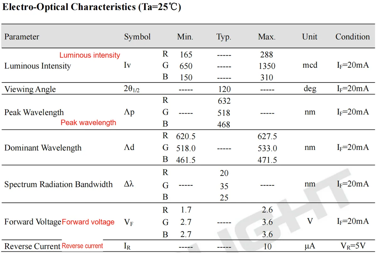
Here, we need to add current-limiting resistors to the RGB LED diodes to ensure that the LEDs will not be damaged due to excessive current. The calculation formula for the current-limiting resistor is as follows:
The meanings of the respective parameters are as follows:
- Vin: Power supply voltage, usually the supply voltage of the LED circuit
- VF: Forward Voltage of an LED. The VF value varies for LEDs of different colors.
- IF: The operating current of an LED, which is typically 20mA (i. e. 0.02A)
3.6.2 PWM Signal Control of RGB LED
Here, we need to insert the Fengya No. 1 Board - Environment and Storage Acquisition Board into the Fengya No. 1 Board - Universal Compatible Expansion Board, and meanwhile turn on the PWM_B, PWM_G and PWM_R options of the SWITCH2 DIP switch on the Fengya No. 1 Board - Environment and Storage Acquisition Board. The physical connection diagram is shown as follows:
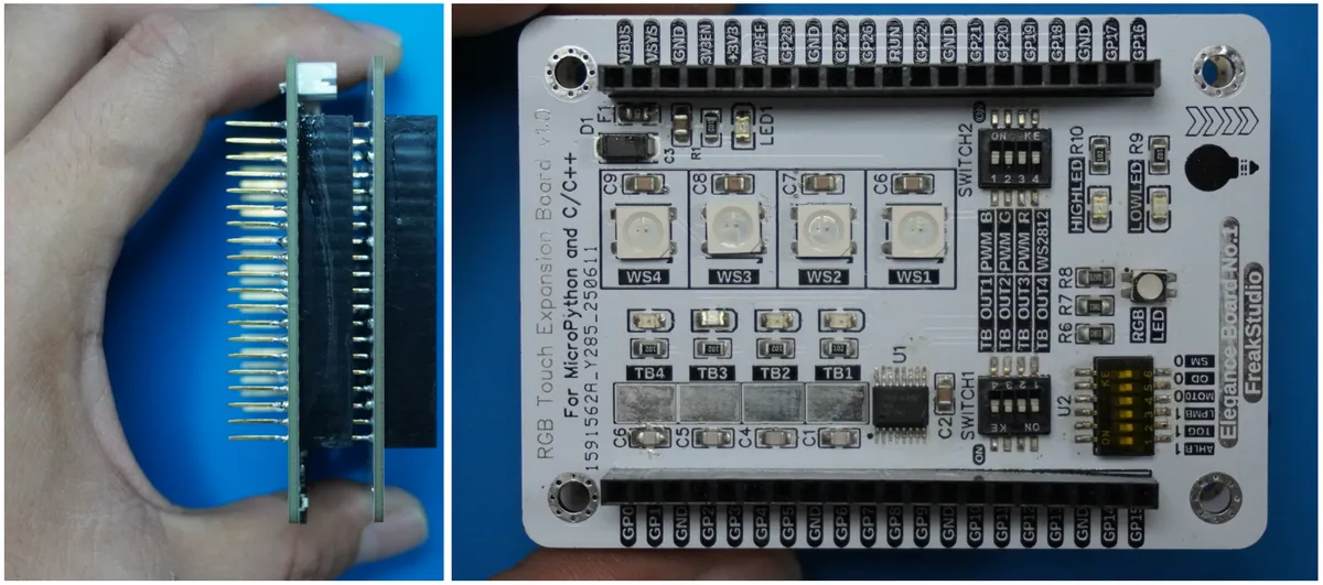
The pin connections are shown in the following table:
LED Color | LED Pin Functions | Pico Pin Numbering (GPIO) | Note |
red | R pin | GPIO19 | Output control of red light brightness |
Green | G pin | GPIO20 | Output control of green light brightness |
blue | Pin B | GPIO21 | Output control of blue light brightness |
All the code for the following experiments is open-source and can be found in the resource package we provide under the elegance-devkit v1\Demo\27 PWM_RGBLED folder.
In the following code, we use the PWM module to control the GPIO pins of the Raspberry Pi Pico to output PWM signals, thereby driving the RGB LED. The sample code is as follows:
# Python env   : MicroPython v1.23.0
# -*- coding: utf-8 -*-
# @Time    : 2024/9/20 3:18 PM
# @Author  : Li Qingshui
# @File    : main.py
# @Description : PWM class usage, drive an RGB LED to produce light of different colors

# ======================================== Import Modules =========================================

# Import hardware-related modules
from machine import Pin, PWM
# Import time-related modules
import time

# ======================================== Global Variables ============================================

# Define a mapping table from color RGB values to PWM duty cycles (common colors)
COLOR_PWM_VALUES = {
    'red': (255, 0, 0),         # Red
    'green': (0, 255, 0),       # Green
    'blue': (0, 0, 255),        # Blue
    'yellow': (255, 255, 0),    # Yellow
    'cyan': (0, 255, 255),      # Cyan
    'magenta': (255, 0, 255),   # Magenta
    'white': (255, 255, 255),   # White
    'black': (0, 0, 0),         # Turn off the LED
}

# ======================================== Functions ============================================

# Convert an 8-bit value (0-255) to a 16-bit PWM value (0-65535)
def map_to_pwm(value: int) -> int:
    """
    Map an 8-bit color value (0-255) to a 16-bit PWM duty cycle (0-65535).

    Args:
        value (int): Color value between 0-255.

    Returns:
        int: PWM duty cycle mapped to the range 0-65535.
    """
    return int(value * 65535 / 255)

# ======================================== Custom Classes ============================================

# RGB LED control class
class RGBLed:
    """
    RGB LED control class, used to drive an RGB LED through PWM to produce light of different colors.

    This class encapsulates the control logic of an RGB LED and supports adjusting the brightness of the red, green and blue channels through PWM,
    thereby displaying a variety of colors. In addition, it supports setting the LED color directly by color name.

    Attributes:
        red_pwm (PWM): PWM instance of the red LED.
        green_pwm (PWM): PWM instance of the green LED.
        blue_pwm (PWM): PWM instance of the blue LED.

    Methods:
        __init__(self, red_pin: int, green_pin: int, blue_pin: int):
            Initialize an RGB LED class instance.

        set_color(self, red_val: int, green_val: int, blue_val: int) -> None:
            Set the color of the RGB LED.

        set_color_by_name(self, color_name: str) -> None:
            Set the color of the RGB LED by color name.
    """

    def __init__(self, red_pin: int, green_pin: int, blue_pin: int):
        """
        Initialize the RGB LED.

        Args:
            red_pin (int): Pin number the red LED is connected to.
            green_pin (int): Pin number the green LED is connected to.
            blue_pin (int): Pin number the blue LED is connected to.
        """
        # Initialize the three PWM channels for red, green and blue
        self.red_pwm = PWM(Pin(red_pin))
        self.green_pwm = PWM(Pin(green_pin))
        self.blue_pwm = PWM(Pin(blue_pin))

        # Set the PWM frequency (typical value is 1000Hz)
        self.red_pwm.freq(1000)
        self.green_pwm.freq(1000)
        self.blue_pwm.freq(1000)

    def set_color(self, red_val: int, green_val: int, blue_val: int) -> None:
        """
        Set the color of the RGB LED.

        Args:
            red_val (int): Red RGB value, range 0-255.
            green_val (int): Green RGB value, range 0-255.
            blue_val (int): Blue RGB value, range 0-255.

        Returns:
            None
        """
        # Map the 8-bit color values to 16-bit PWM values and set the duty cycle
        self.red_pwm.duty_u16(map_to_pwm(red_val))
        self.green_pwm.duty_u16(map_to_pwm(green_val))
        self.blue_pwm.duty_u16(map_to_pwm(blue_val))

    def set_color_by_name(self, color_name: str) -> None:
        """
        Set the color of the RGB LED by color name.

        Args:
            color_name (str): Color name, such as 'red', 'green', 'blue', etc.

        Returns:
            None
        """
        # Get the RGB value corresponding to the color
        # Get the value for the specified key from the dictionary, return the default value (0, 0, 0) if the key is not found
        color_values = COLOR_PWM_VALUES.get(color_name.lower(), (0, 0, 0))
        # Set the color of the RGB LED
        # Use Python's unpacking operator to pass the three values in the tuple respectively to
        # the three parameters red_val, green_val and blue_val of the set_color() method
        self.set_color(*color_values)

# ======================================== Initialization ==========================================

# Power-on delay of 3 s
time.sleep(3)
# Print debug information
print("FreakStudio : Use PWM to drive a RGB LED")
# Initialize the RGB LED class: red pin is 2, green pin is 3, blue pin is 4
rgb_led = RGBLed(red_pin=2, green_pin=3, blue_pin=4)

# ========================================  Main Program  ===========================================

# Set to a color with medium red, brightest green and dim blue
rgb_led.set_color(128, 255, 64)
# Delay 3s
time.sleep(3)

# Loop to control the RGB LED to change colors
while True:
    # Set to red and delay 1s
    rgb_led.set_color_by_name('red')
    time.sleep(1)
    # Set to green and delay 1s
    rgb_led.set_color_by_name('green')
    time.sleep(1)
    # Set to blue and delay 1s
    rgb_led.set_color_by_name('blue')
    time.sleep(1)
    # Set to yellow and delay 1s
    rgb_led.set_color_by_name('yellow')
    time.sleep(1)
    # Set to cyan and delay 1s
    rgb_led.set_color_by_name('cyan')
    time.sleep(1)
    # Set to magenta and delay 1s
    rgb_led.set_color_by_name('magenta')
    time.sleep(1)
    # Set to white and delay 1s
    rgb_led.set_color_by_name('white')
    time.sleep(1)
    # Set to black and delay 1s
    rgb_led.set_color_by_name('black')
    time.sleep(1)
Here, we first define a global dictionary that stores the RGB values of common colors, where each color corresponds to an RGB tuple; for example, red is (255,0, 0), and then we define a map_to_pwm function that maps RGB values (ranging from 0 to 255) to PWM values (ranging from 0 to 65535).
Next, we defined an RGB LED control class to encapsulate the control logic of the RGB LED. In the initialization method, we pass the numbers of the red, green, and blue pins connected to the RGB LED, initialize these pins to the PWM output mode respectively, set their PWM frequency to 1000Hz, and define two methods:
set_color_by_name ()method: Sets the color of the RGB LED by color name. It looks up the RGB value corresponding to the color name from the global dictionaryCOLOR_PWM_VALUES, and returns(0,0, 0)by default if no match is found, which turns off the LEDset_color ()method: Used to set the color of the RGB LED, which accepts three parameters (the duty cycles of red, green and blue, ranging from 0 to 255). It usesmap_to_pwm ()to map the RGB values to a 16-bit PWM duty cycle, and sets the PWM value of each color channel via theduty_u16 ()method
Burn the code, and you will see the on-board RGB LED cycle through and emit lights of different colors.
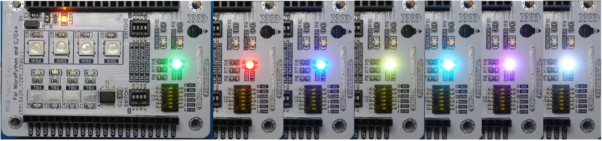
3.6 Application Experiment.mp4 21.8 MB
3.7 PWM Signal Driven Buzzer
3.7.1 Basic Knowledge of Buzzer
A buzzer is an electronic component designed to generate sound, which is widely used in various devices to emit warning tones, prompt tones or other sound effects. According to different working principles, buzzers mainly fall into the following types: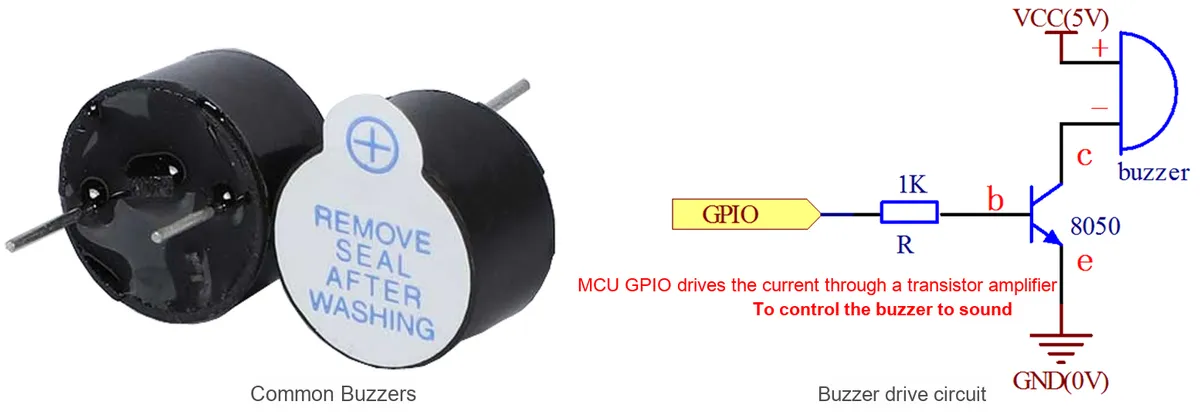
- Active Buzzer: An active buzzer has an integrated oscillation circuit inside to generate a fixed-frequency oscillation signal, which drives the piezoelectric buzzer to produce sound via the piezoelectric effect. Simply put, when voltage is applied, the piezoelectric material undergoes mechanical deformation to generate sound; there are also some active buzzers that operate on the electromagnetic vibration principle – when current flows through the coil, a magnetic field is generated, which causes an iron piece or diaphragm to vibrate, thus producing sound.
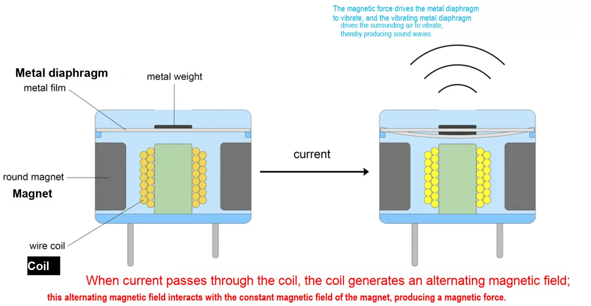
- Passive Buzzer: A passive buzzer has no internal oscillation circuit. It consists of a coil, an iron plate or a diaphragm, and requires an external signal to drive it to produce sound.
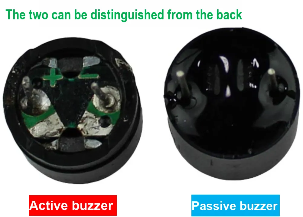
In practical applications, the two have different focuses:
- Active buzzer: It is suitable for scenarios requiring simple and fixed sound, but its drawback is that the frequency of the sound it generates is fixed and cannot be adjusted.
- Passive Buzzer: We can adjust the frequency and duty cycle of the external signal to change the sound frequency and pitch produced by the buzzer, which is suitable for scenarios that require generating multiple tones or audio effects, such as music playback, alarm systems, etc.
3.7.2 PWM Signal Drives Buzzer to Output MIDI Music
In the following experiment, we need to insert the Fengya No. 1 Board - Universal Compatible Expansion Board into the Fengya No. 1 Board - OLED Display and Interaction Expansion Board, and at the same time turn on the Fengya No. 1 Board - OLED Display and Interaction Expansion Board 's SWITCH1 DIP switch' s BUZZER option:
In the following code, we use a PWM signal to drive a passive buzzer to realize the function of playing the MIDI music *Twinkle Twinkle Little Star*. MIDI (Musical Instrument Digital Interface) is a protocol for communication between electronic musical instruments, computers and other audio devices. For MIDI music, different musical notes can correspond to signals of different frequencies; for example, the frequency corresponding to MIDI number 60 (C4) is 261Hz;By adjusting the duty cycle of the PWM signal, the volume of the music can be controlled. Then we adjust the duration of each musical note and play each note in the specified sequence, so that the buzzer can generate the corresponding MIDI music.
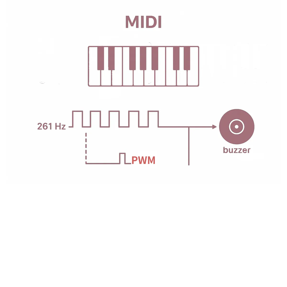
All the code for the following experiments is open-source and can be found in the resource package we provide elegance-devkit v1\Demo\28 PWM_Buzzer folder.
Here, we use the GPIO9 of the Raspberry Pi Pico to connect to the signal input terminal of the buzzer, and the sample code is shown below:
# Python env   : MicroPython v1.23.0
# -*- coding: utf-8 -*-
# @Time    : 2024/9/19 9:09 PM
# @Author  : Li Qingshui
# @File    : main.py
# @Description : PWM class usage, drive a buzzer to play MIDI music

# ======================================== Import Modules =========================================

# Import hardware-related modules
from machine import Pin, PWM
# Import time-related modules
import time

# ======================================== Global Variables ============================================

# Mapping from notes to frequencies
NOTE_FREQS = {
    'C4': 261, 'D4': 293, 'E4': 329, 'F4': 349, 'G4': 392, 'A4': 440, 'B4': 493,
    'C5': 523, 'D5': 587, 'E5': 659, 'F5': 698, 'G5': 784, 'A5': 880, 'B5': 987,
    'C3': 130, 'D3': 146, 'E3': 164, 'F3': 174, 'G3': 196, 'A3': 220, 'B3': 246
}

# Melody and rhythm of Twinkle Twinkle Little Star: each note and its duration
MELODY = [
    ('C4', 400), ('C4', 400), ('G4', 400), ('G4', 400), ('A4', 400), ('A4', 400), ('G4', 800),
    ('F4', 400), ('F4', 400), ('E4', 400), ('E4', 400), ('D4', 400), ('D4', 400), ('C4', 800),
    ('G4', 400), ('G4', 400), ('F4', 400), ('F4', 400), ('E4', 400), ('E4', 400), ('D4', 800),
    ('G4', 400), ('G4', 400), ('F4', 400), ('F4', 400), ('E4', 400), ('E4', 400), ('D4', 800),
    ('C4', 400), ('C4', 400), ('G4', 400), ('G4', 400), ('A4', 400), ('A4', 400), ('G4', 800),
    ('F4', 400), ('F4', 400), ('E4', 400), ('E4', 400), ('D4', 400), ('D4', 400), ('C4', 800)
]

# ======================================== Functions ============================================

# ======================================== Custom Classes ============================================

# Buzzer class
class Buzzer:
    """
    Buzzer class, used to drive a buzzer with PWM to play notes and melodies.

    This class encapsulates the buzzer control logic and supports playing a single note or a melody. By adjusting the frequency and duty cycle with PWM,
    it can produce sounds of different pitches and durations.

    Attributes:
        buzzer (PWM): PWM instance of the buzzer, used to control frequency and duty cycle.

    Methods:
        __init__(self, pin: int):
            Initialize the buzzer class instance.

        play_tone(self, frequency: int, duration: int) -> None:
            Play a note.

        play_melody(self, melody: list) -> None:
            Play a melody.
    """

    def __init__(self, pin: int):
        """
        Initialize the buzzer.

        Args:
            pin (int): GPIO pin number the buzzer is connected to.
        """
        # Set up PWM to drive the buzzer
        self.buzzer = PWM(Pin(pin))
        # Initial frequency is 2000
        self.buzzer.freq(2000)
        # Initial duty cycle is 0
        self.buzzer.duty_u16(0)

    def play_tone(self, frequency: int, duration: int) -> None:
        """
        Play a note.

        Args:
            frequency (int): Frequency of the note (Hz).
            duration (int): Duration of the note (ms).

        Returns:
            None
        """
        # Set the buzzer frequency
        self.buzzer.freq(frequency)
        # Set duty cycle to 50%
        self.buzzer.duty_u16(32768)
        # Duration
        time.sleep_ms(duration)
        # Stop sounding
        self.buzzer.duty_u16(0)

    def play_melody(self, melody: list) -> None:
        """
        Play a melody.

        Args:
            melody (list): List of notes and durations of the melody; each element is a tuple (note, duration).
                           note is the note name (e.g. 'C4'), and duration is the duration (ms).

        Returns:
            None
        """
        for note, duration in melody:
            # Get the frequency from the note
            frequency = NOTE_FREQS.get(note, 0)
            if frequency:
                # Play the note
                self.play_tone(frequency, duration)
            # Interval between notes
            time.sleep_ms(10)

# ======================================== Initialization ==========================================

# Power-on delay of 3 s
time.sleep(3)
# Print debug information
print("FreakStudio : Use PWM to drive a buzzer to play MIDI music")
# Initialize the buzzer object
buzzer = Buzzer(pin=9)

# ========================================  Main Program  ===========================================

# Play the music in a loop
while True:
    # Play the melody "Für Elise"
    buzzer.play_melody(MELODY)
In the above code, we first declare a dictionary NOTE_FREQS to store musical note names (e. g., 'C4') and their corresponding frequencies in hertz, then define a MELODY list to store musical notes and their corresponding durations in milliseconds, which is the melody data for *Twinkle Twinkle Little Star*.
Then a custom Buzzer class is defined to control the buzzer, which has the following methods:
play_tonemethod: used to play a musical note with specified frequency and durationplay_melodymethod: Used to iterate through a melody list, play the corresponding tone for each musical note, and add a short interval between each musical note
In the main program section, we create an Buzzer class instance, connect it to the GP22 pin, and then play the melody "Twinkle Twinkle Little Star" in an infinite loop; after flashing the code, you can hear the buzzer emit sound according to the predefined melody data, realizing the function of playing MIDI music.
3.7 Application Experiment.mp4 35.6 MB
References
- RP2040 (Raspberry Pi Pico) General-purpose Timer & RTC
https://www.taterli.com/7561
- 0x01 Timer
https://www.ruanx.net/rp2040-note-3/
- Looking for an example explaining Alarm pools
https://forums.raspberrypi.com/viewtopic.php?t=349734
- Essentials of Microcontroller Use Learning about Peripherals: Timers
https://www.renesas.com/us/en/support/engineer-school/mcu-programming-peripherals-02-timer
- Interesting PWM on Raspberry Pi RP2040 microcontroller
https://www.electronicsweekly.com/blogs
- RP2040 Study Notes (2): Various Low-Speed Peripherals
https://www.ruanx.net/rp2040-note-2/
- RP2040 (Raspberry Pi Pico) PWM
https://www.taterli.com/7548
- ISD91200 Series Technical Reference Manual
https://www.manualslib.com/manual/1897471/Nuvoton-Isd91200-Series.html?page=176
- Timers in MicroPython
https://www.coderdojotc.org/micropython/advanced-labs/13-timers/
- mpy-lib/keyboard/mechanical-button/single-button/
https://github.com/micropython-Chinese-Community/mpy-lib/tree/master/keyboard/mechanical-button
- Understanding Difference between Active and Passive Buzzer and How to use it with Arduino
https://circuitdigest.com/microcontroller-projects/understanding-difference-between-active-and-passive-buzzer-with-arduino
Version Record
Version Number | Modifier | Time | Content |
v1.0.0 | Li Zisheng | 2025/09/17 | Initialize the document, based on MicroPython version v1.23.0. |
v1.0.1 | Li Zisheng | 2025/12/05 | Some images have been modified. |
v1.1.0 | Li Zisheng | 2025/12/15 | Modified the complete image. |
v1.1.1 | Li Zisheng | 2025/12/21 | Optimized some of the documents. |