In the previous article, we introduced the I2C Communication Protocol, which is an on-board communication protocol suitable for single-master multi-slave or multi-master multi-slave architectures. In this article, we will introduce another on-board communication protocol - SPI.
1.1.1 Introduction to SPI Serial Peripheral Interface
SPI, short for Serial Peripheral Interface, is as the name suggests a serial peripheral device interface. It is a synchronous data communication standard operating in full-duplex mode, named by the former Motorola company. The SPI data rate typically ranges from 1 to 70 MHz, with byte lengths varying from 8 bits and 12 bits to multiples of these values.
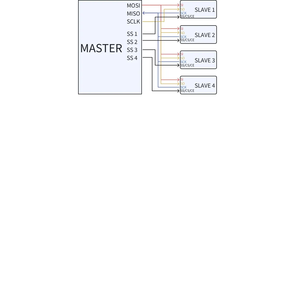
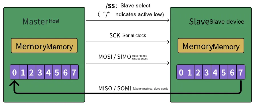
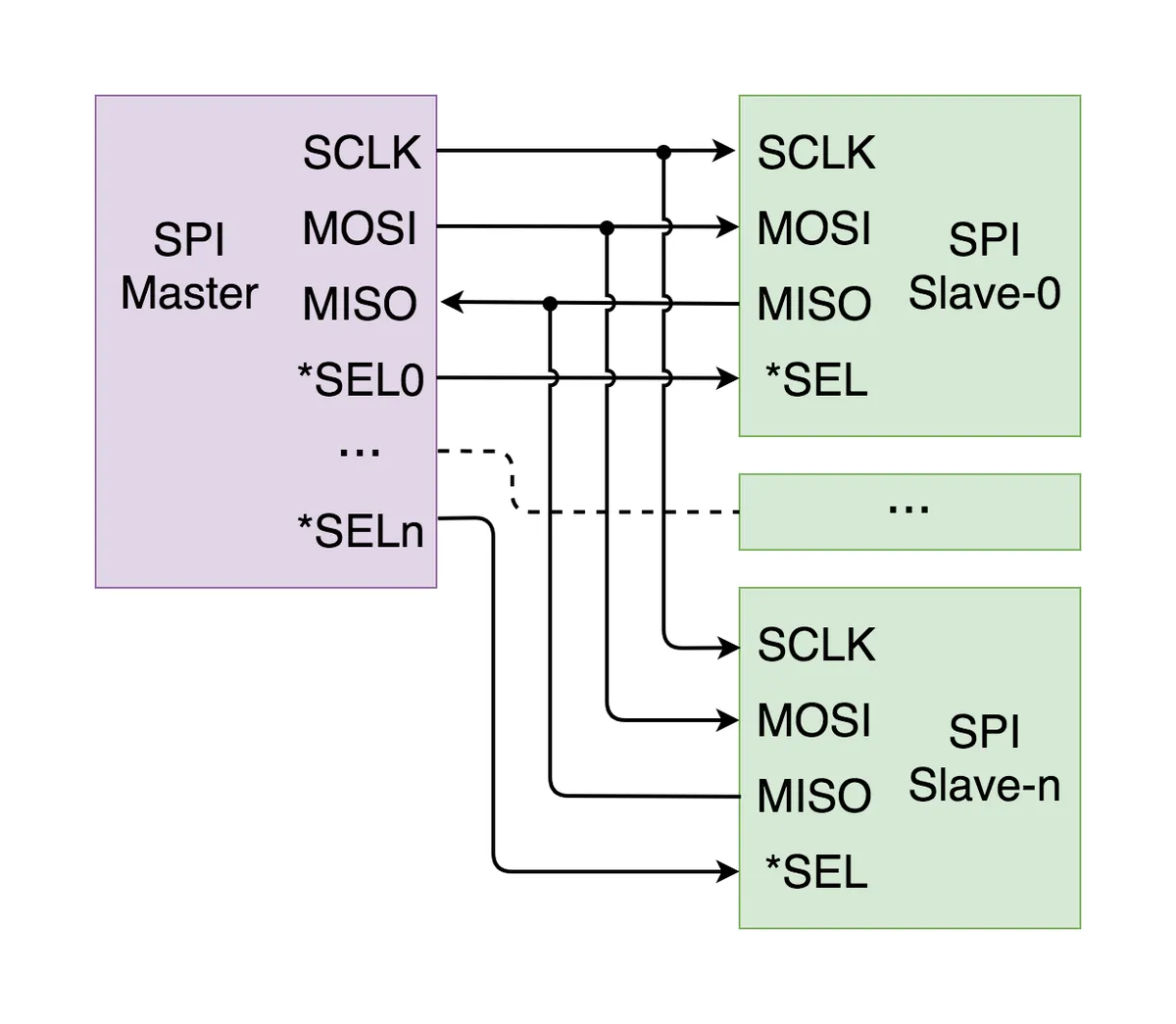
SPI is a single-master Communication Protocol, which means that only one central device in the bus can initiate communication. When SPI operates in master-slave mode, there is typically one master device and one or more slave devices. When multiple devices are present, devices are selected or deactivated via chip select signals. Typically, SPI in standard mode uses 3 communication buses and 1 chip select line, which are defined as follows:
abbreviation
Full name
Function
CS/nSS
Chip Select
The slave device chip select/enable signal is controlled by the master device and is active low.
SCLK
Serial Clock
Clock signal, generated by the master device
MOSI/PICO
Main Out, Sub In
(master out, slave in)
Peripheral In,Controller Out
Master device data input, slave device data output
MISO/POCI
Main In, Sub Out
(master in, slave out)
Peripheral Out,Controller In
Master device data output, slave device data input
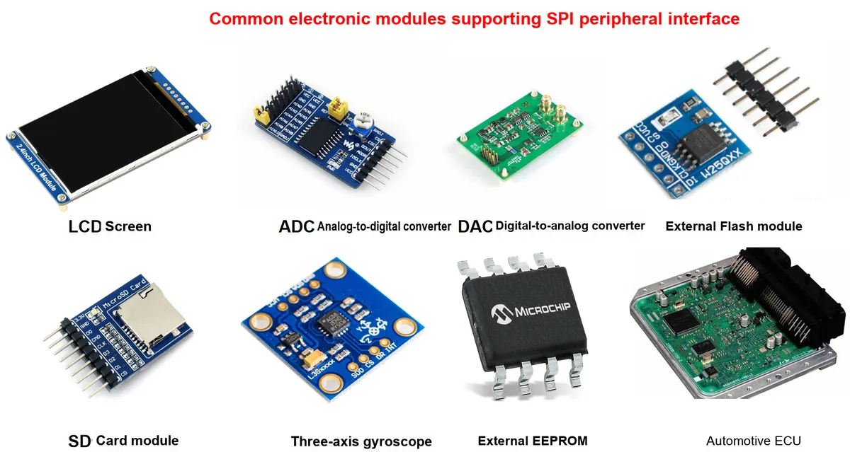
SPI interface is mainly applied between EEPROM, FLASH, real-time clock, AD converter, as well as digital signal processors and digital signal decoders. The common electronic modules supporting SPI peripheral interfaces are as follows:
1.1.2 Development History of SPI (Serial Peripheral Interface)
1.1.2.1 Serial Communication vs. Parallel Communication
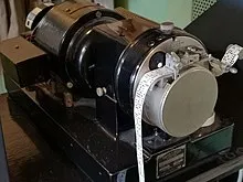
Here, let’s start with the early computers. As everyone knows, when computers were first invented, they typically used punched paper tape to store and execute programs:
Creed Model 6S/2 5-hole paper tape reader
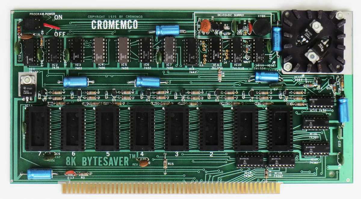
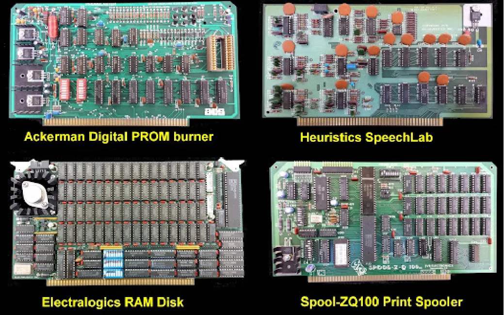
Paper tape was inconvenient for storage and suffered from severely limited reading speed. With the continuous development of electronic computer technology, Cromemco introduced the first viable alternative to punch tape for program storage in 1976 — the Bytesaver, a programmable memory board that could be used on MITS Altair and S-100 bus microcomputer systems. The Bytesaver featured slots for 8 UV-erasable EPROMs, offering up to 8KB of storage capacity. EPROMs could be programmed via the Bytesaver or read as computer memory.
Photo of the Bytesaver, the first viable alternative to storing programs on punched paper tape; it reduced the load time for Microsoft 8K Basic from 7 minutes (Teletype Model 33 tape reader) to under one second
At that time, people still needed to connect multiple address lines and data lines to the memory to read and write data in a parallel communication manner, and might also require multiple clocks and control lines, as well as buffer and bus latch devices to hold data when transferring it between chips, making data reading and writing extremely complicated and inconvenient.
Microcomputer systems developed in the late 1980s, such as the S-100, VME and PCI, adopted wide parallel buses to accelerate processing. While such wide parallel buses offer high communication speeds, they are inconvenient for wiring and impose extremely strict requirements on the timing synchronization of individual signals.
Circuit unit of a microcomputer system developed in the late 1980s
In the late 20th century, with the invention of serial buses such as I2C and SPI, we only need a small number of data lines and clock lines to realize communication between devices, which features simple protocols and convenient wiring.
The so-called serial Communication Protocol refers to a communication mode in which data is transmitted bit by bit in the form of data bits between devices through a small number of data signal lines (generally less than 8), ground lines and control signal lines.
Here is a quote from the renowned director Woody Allen on his understanding of time:
"Time is the thing that nature uses to stop everything from happening at once. "
- Woody Allen, director, representative works include *Manhattan*, *Hannah and Her Sisters*, *Vicky Cristina Barcelona*, etc.
We can simply explain serial communication as "when not everything needs to happen simultaneously, data can be transmitted over a single wire in a time-division manner".
Compared with parallel Communication Protocol, serial communication can save the hardware cost of data lines (especially in long-distance scenarios) and the wiring area of PCB. Meanwhile, compared with parallel communication, serial communication features stronger anti-interference capability, longer communication distance, and lower requirements for clock synchronization.
1.1.2.2 Introduction of the SPI Serial Peripheral Interface
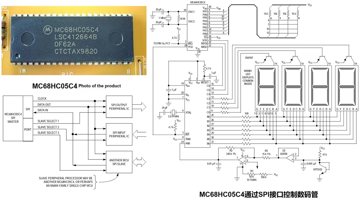
The SPI protocol was defined by Motorola in 1983 for three MC68HCXX series processors, and its functions were described in the 1984 manual; the MC68HC05C4 was one of the first microcontrollers to integrate SPI into hardware.
SPI actually lacks a formal and unified standard:
Different transmission word lengths are common
Some devices do not use chip select, but instead use other methods to manage the entry into and exit from the protocol finite-state machine.
Chip select is sometimes active-high instead of active-low.
Some devices transmit the least significant bit first
The signal level depends entirely on the chips involved
Meanwhile, the SPI electrical specifications also vary from device to device.
The timing of some devices differs from the CPOL/CPHA modes of Motorola.
At the same time, some other devices require additional flow control signal lines or insertion of dummy bytes when using SPI.
The AN991 "Using the Serial Peripheral Interface to Communicate Between Multiple Microcomputers" revised by NXP in 2002 is currently regarded as an unofficial official SPI standard.
1.1.3 Introduction to the SPI Serial Peripheral Interface Protocol
1.1.3.1 Protocol Layer of SPI Serial Peripheral Interface
1. Overview of SPI Communication Process
When communicating via SPI, the entire process can be simplified as follows:
Initialization: The master initializes SPI communication by configuring parameters such as clock speed, data format, and chip select pins.
Chip Select: The master device selects the slave device it intends to communicate with by activating its corresponding Slave Select (SS) pin.
Clock Signal: The master device generates clock pulses (SCLK) to synchronize data transmission between itself and the selected slave device.
Data Transmission (Master to Slave): The master device transmits data (bits) serially over the Master Out Slave In (MOSI) line, with each bit synchronized to the clock signal.
Data Reception (from Slave to Master): The slave receives data on its MOSI line, and simultaneously sends its own data back to the master on the MISO (Master In, Slave Out) line.
Data Exchange: The master device and slave device exchange data in full-duplex mode, which means they can transmit and receive data simultaneously.
Communication Termination: Once the required data exchange is completed, the master device disables the chip select pin, indicating the end of communication with the slave device.
2.Key Essentials of the SPI Protocol
The basic key points of the SPI protocol can be summarized as follows:
The Slave Select (SS) signal essentially acts as the start and end signal for SPI communication: a high-to-low transition of the nSS signal serves as the start signal for SPI communication; conversely, a low-to-high transition of the nSS signal marks the end of SPI communication. When a slave device detects that its own nSS pin is pulled low, it recognizes that it has been selected by the master and prepares to communicate with the master.
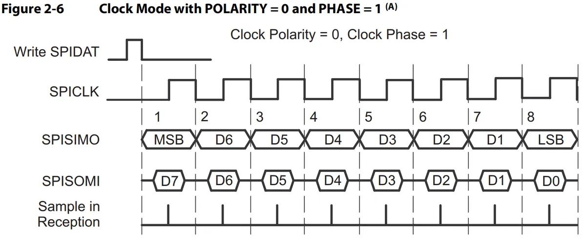
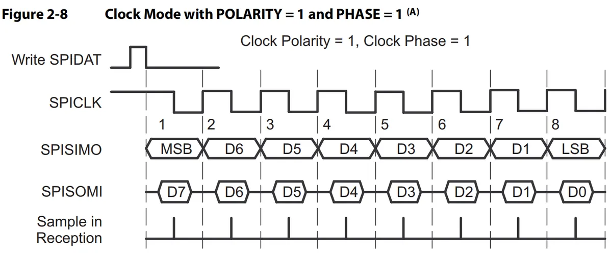
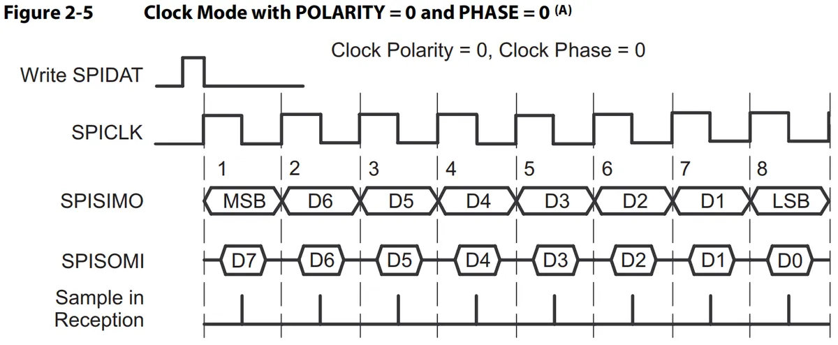
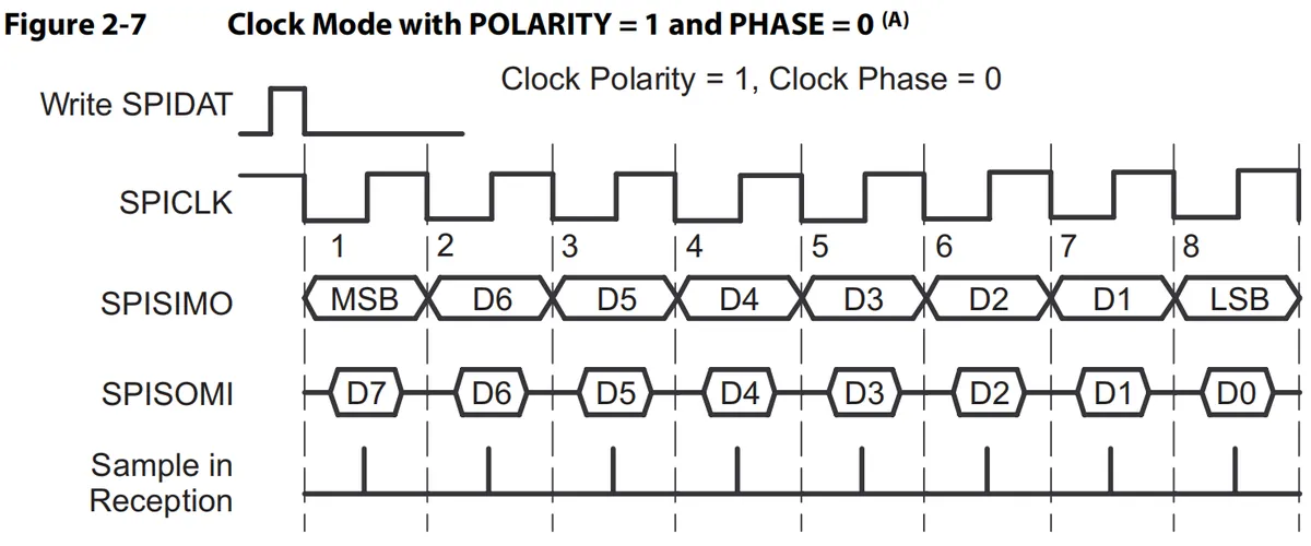
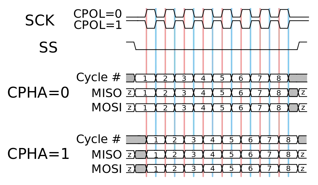
Data synchronization is actually governed by the SCLK signal on the host, and the transmission of data bits must be synchronized with the clock signal: the clock signal, via Clock Polarity (CPOL) and Clock Phase (CPHA), controls when data is exchanged between two SPI devices and when the received data is sampled.
Wherein:
CPOL Clock Polarity: This configuration determines the idle state of the clock signal
CPOL = 0: SCLK is at low level when idle
CPOL = 1: SCLK is at high level when idle
CPHA Clock Phase: determines when data is sampled and when shifting occurs within each clock cycle
CPHA = 0: Sampling is performed on the odd edges of SCLK
CPHA = 1: Sampling is performed on the even edges of SCLK.
Data transmission usually involves a data exchange. When the master sends data to the slave, the slave also sends data to the master. Unlike the UART serial port or I2C bus we discussed earlier, the SPI protocol does not distinguish between data receivers and transmitters. Instead, full-duplex data transmission occurs during each SPI clock cycle, where both the master and the slave transmit and receive data simultaneously (the master transmits one bit of data on the MOSI line for the slave to read, while the slave transmits one bit of data on the MISO line for the master to read).Even if only one-way data transmission is performed, for example, the master only sends valid data to the slave and the master does not care about the data sent by the slave, such an order must still be maintained. This means that no matter what data is received, something must actually be sent.
Actually, the full-duplex transmission of SPI is implemented by shift registers, which achieves the purpose of exchanging master and slave data through shifting within 8 clock cycles:
When generating the clock signal, the master synchronously outputs its shift register via the MOSI line. Meanwhile, the slave reads the first bit from the master at the MOSI pin, stores it into memory, and then outputs the last bit of data via the MISO line. The master node reads the first bit of the data sent by the slave at the MISO pin and stores it into memory for later processing. This entire process continues until all data bits have been exchanged, after which the master sets the clock to an idle state and disables the slave via the chip select (CS) signal.
3. Clock Polarity and Phase Relationship
The following lists the data acquisition conditions of the SPI bus under different configurations of clock polarity and phase:
When CPHA = 1, sampling is performed on the even edges of SCLK:
When CPOL = 0, SCLK is at a low level when idle, the data signal changes on the rising edge and is sampled on the falling edge.
The input data is latched on the rising edge of SCLK
When CPOL = 1, SCLK is at a high level when idle, the data signal changes on the falling edge and is read on the rising edge
The input data is latched on the falling edge of SCLK
When CPHA = 0, sampling is performed on the odd edges of SCLK:
When CPOL = 0, SCLK is at a low level in the idle state, the data signal changes on the falling edge and is sampled on the rising edge.
The input data is latched on the rising edge of SCLK
When CPOL = 1, SCLK is at a high level in the idle state, the data signal changes on the rising edge and is sampled on the falling edge.
The input data is latched on the rising edge of SCLK
By configuring CPOL and CPHA, we can achieve a 180-degree phase shift of the clock signal and a data transmission delay of half a clock cycle.
1.1.3.2 Electrical Specifications of SPI Serial Peripheral
1. Connection Mode of SPI Serial Peripheral
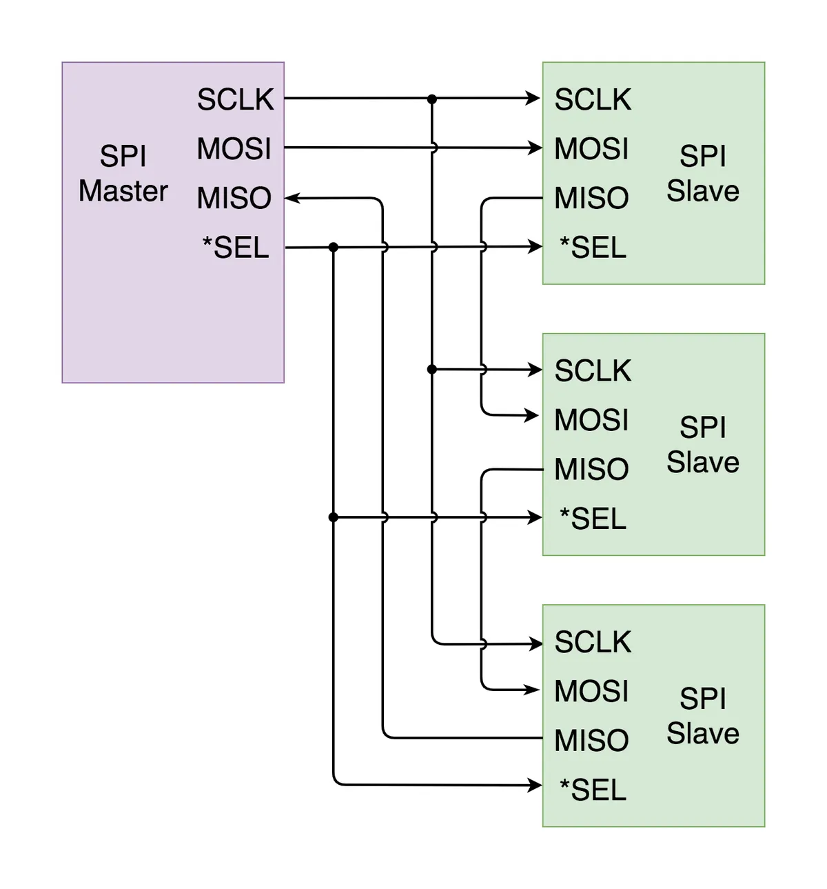
SPI serial peripheral has the following two connection modes for one master and multiple slaves:
Master and independent slave architecture
In this case, the master must provide multiple independent slave chip select signals, and typically only one slave communicates with the master at a time in such a system. This architecture is commonly used in Data Acquisition systems, where multiple analog-to-digital converters (ADCs) and digital-to-analog converters (DACs) need to be connected individually.
Daisy-chained slave structure
A daisy-chain slave requires the master to provide a unique slave select signal; this architecture mandates that all slaves be enabled simultaneously. Data is initiated by the master as usual, and then sequentially transferred through all the slaves. Typical applications include cascaded multi-channel input serializers and output drivers in industrial-grade I/O modules.
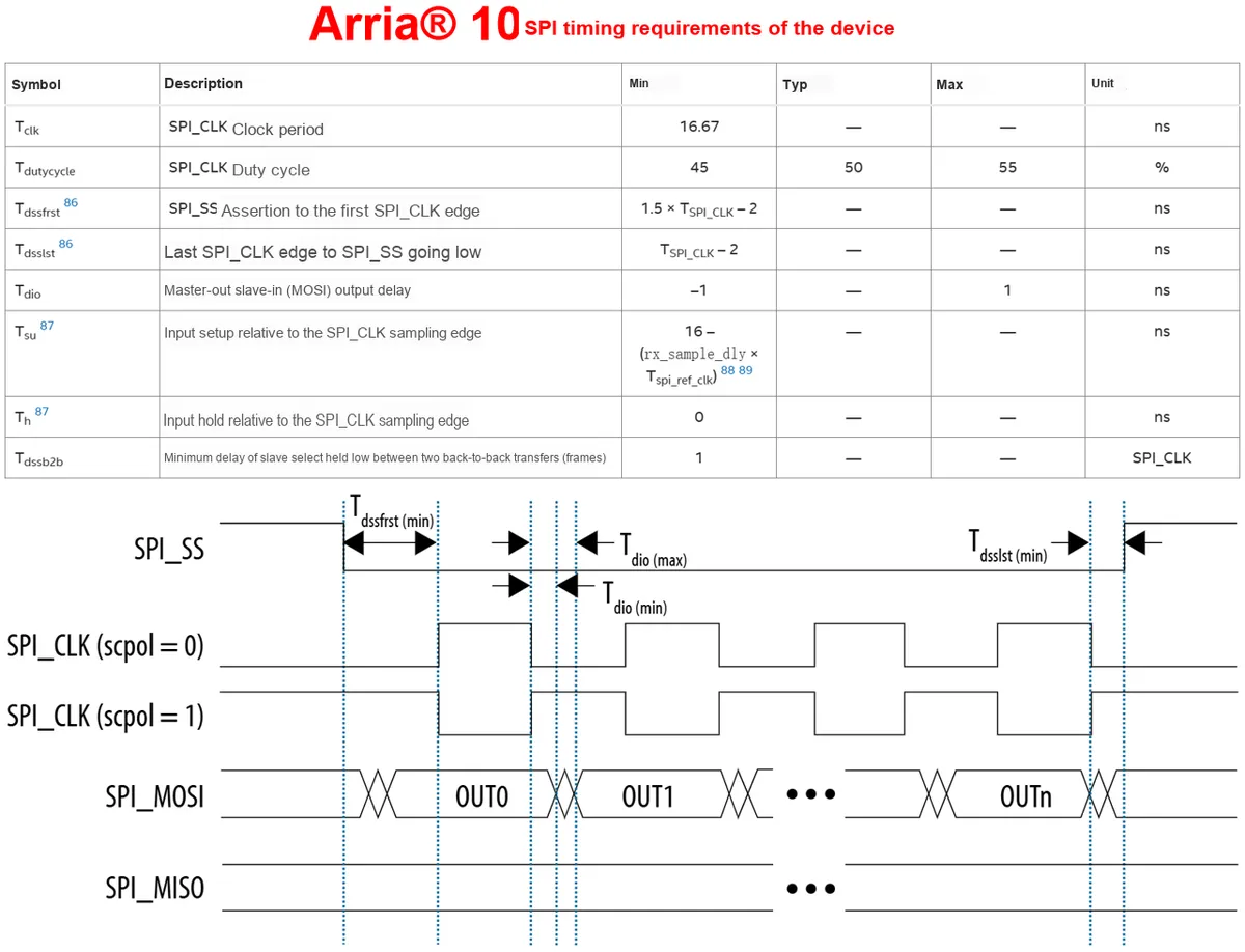
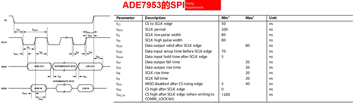
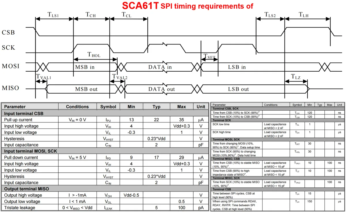
2. Timing of SPI Serial Peripheral
The SPI serial peripherals of different chips have different timing requirements. Below we list the SPI serial peripheral timing requirements of several common chips.
The basic parameters include the CS to SCLK edge, SCLK cycle, SCLK low pulse width, SCLK high pulse width, data output valid time after SCLK edge, data input setup time before SCLK edge, data input hold time after SCLK edge, data output fall time, data output rise time, SCLK rise time, SCLK fall time, MISO disable time after CS rising edge, CS high time after SCLK edge, CS high time after SCLK edge, etc.Different chips may use slightly different names for the above parameters, which will not be introduced one by one here. Those who are interested can refer to the relevant manuals by themselves.
1.1.4 Advantages and Disadvantages of the SPI Protocol
For UART serial communication, it has the following drawbacks:
Since serial ports operate on asynchronous communication without a synchronization clock line, devices using serial ports must set the same data rate in advance. In addition, the clock rates of the serial port's receiver and transmitter need to be approximately consistent; otherwise, data garbling may occur. Meanwhile, when transmitting a piece of 8-bit data, there are at least two synchronization bits (i. e., one start bit and one stop bit), which means that transmitting every 8 valid data bits requires the transmission time of 10 bits, resulting in low transmission efficiency.
The core drawback of UART is that it is only suitable for communication between two devices. Although multiple devices can be connected to a single serial port through external circuit design, bus contention will inevitably arise.
In addition, the UART communication rate is not high, and the UART peripherals of most chips only support a maximum rate of 230400 bits/s.
Simply put, serial communication is suitable for scenarios where only two devices are transmitting data.
Compared with UART serial communication, SPI uses separate data lines and clock lines to enable synchronization between the transmitting and receiving devices, and has the following advantages:
High Speed: Compared with other serial Communication Protocols such as I2C or UART, SPI is renowned for its high-speed data transmission capability, which makes it suitable for applications requiring fast data exchange.
Full-duplex communication: SPI supports full-duplex communication, which enables simultaneous data transmission and reception between the master device and multiple slave devices. This feature improves the efficiency of data exchange.
Direct Communication: SPI enables direct communication between the master and slaves without requiring complex addressing schemes. Each slave device is assigned a dedicated Slave Select (SS) pin, which facilitates such direct communication.
Low overhead: Compared with other Communication Protocols, the SPI protocol has the minimum overhead, which achieves efficient data transmission and reduces the processing burden on the microcontroller.
However, the SPI Communication Protocol also has the following drawbacks:
Limited number of connections: SPI is essentially a master-slave protocol, which limits the number of devices that can be connected to a single bus. Each slave device requires a dedicated Slave Select (SS) pin, which may restrict the scalability of the system.
No built-in error checking: Unlike some other protocols such as I2C, SPI does not incorporate a built-in error checking mechanism. Therefore, it relies on higher-level protocols or additional hardware to ensure data integrity and error detection.
Complex Bus Management: In systems with multiple slave devices, managing the Slave Select (SS) signals can become complicated. Ensuring proper timing and synchronization among multiple slaves may require careful design considerations.
Limited cable length: Due to signal integrity issues at higher frequencies, SPI communication is generally limited to relatively short cable lengths. Longer cable lengths will cause signal attenuation and interference, thereby affecting data reliability.
Not suitable for multi-master configuration: SPI does not support multi-master configurations where multiple devices act as masters on the same bus, and this limitation restricts its applicability in systems requiring dynamic or decentralized control.
No acknowledgment mechanism: There is no acknowledgment mechanism to confirm whether data has been received.
1.1.5 Types of SPI Protocol
The SPI protocol can be subdivided into the following types:
Standard SPI:
This is the most common SPI type, which is characterized in that a single master device communicates with one or more slave devices via separate chip select lines. It operates in full-duplex mode, allowing simultaneous data transmission and reception.
Single-wire SPI (SSI):
SSI uses a shared chip select line for all connected slave devices, which simplifies hardware configuration.
Multi-master SPI:
Multiple master devices share communication with one or more slave devices. Each master station can initiate communication independently, thus enabling more complex network configurations.
Daisy-chain SPI:
Daisy-chain SPI allows multiple slave devices to be connected in a daisy-chain configuration, with data passing through each slave device in sequence. This reduces the number of required chip select lines, making it suitable for applications with limited pins. However, delays may be introduced as data propagates through the chain.
QSPI:
It enhances the standard SPI by increasing the data transfer rate through the use of four data lines (MOSI, MISO, and two clock lines). This parallel data transmission enables faster communication, making it an ideal choice for high-speed applications such as flash memory and displays.
SPI Bus:
The SPI bus is a variant of the SPI protocol, which adopts a shared data bus to allow multiple master and slave devices to communicate via the same set of data lines. It utilizes additional control signals for arbitration and synchronization to ensure orderly communication in a multi-device environment.
eSPI:
eSPI is an advanced version of SPI designed for modern computing systems. It delivers features including higher data rates, expanded address space, and additional functionalities for system management and security. It is commonly used in embedded systems, servers and networking devices.
1.2 Basic Structure and Concepts of SPI Peripherals
1.2.1 Basic Structure of SPI Peripheral
The SPI peripheral of the Raspberry Pi Pico is based on the SSP (Synchronous Serial Port) controller, which is a slave module of the AMBA Advanced Microcontroller Bus Architecture and connects the AMBA to the APB peripheral bus.
SSP supports the SPI protocol, synchronous serial protocol and Microwire protocol, and the protocol it uses can be changed by configuring the corresponding registers.
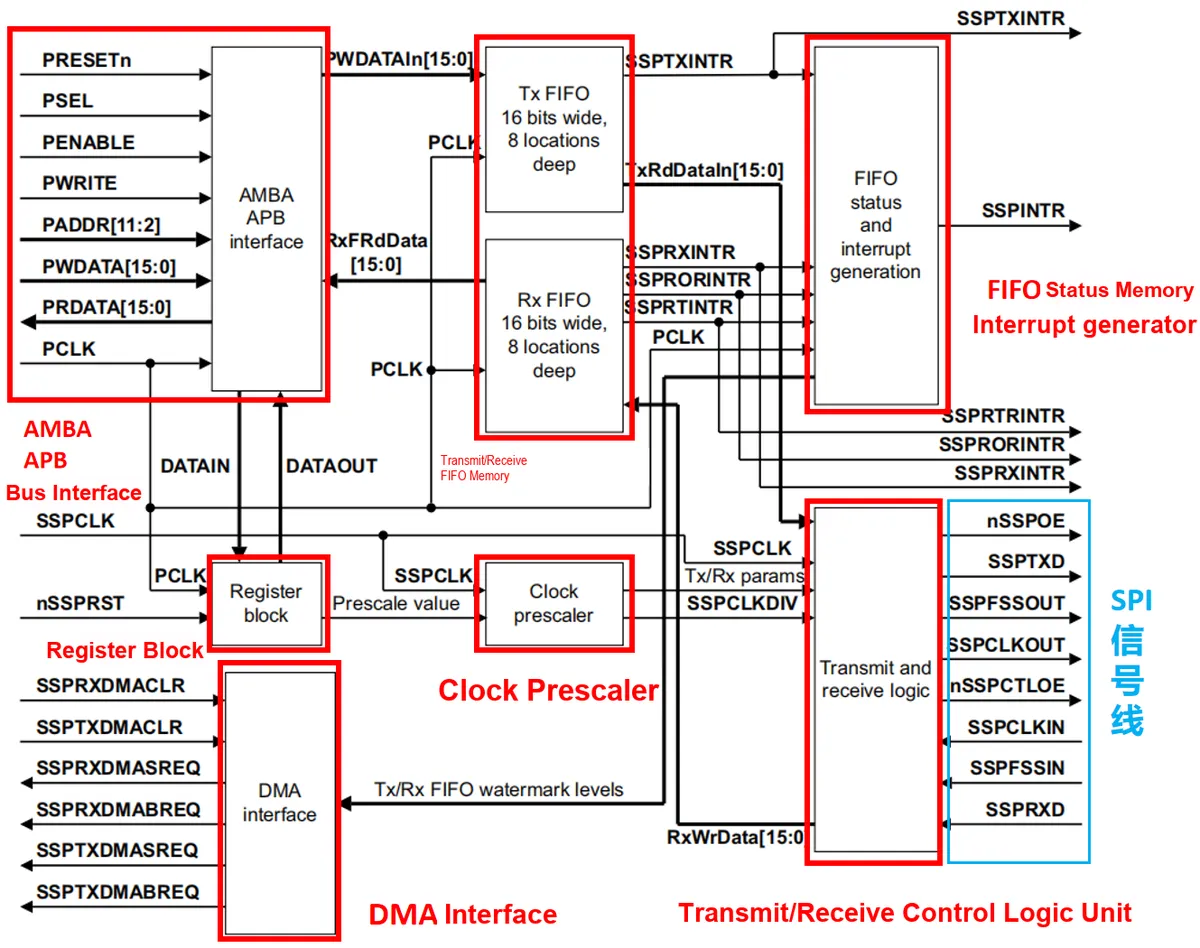
The SSP structure diagram is as follows:
It can be divided into the following parts:
AMBA APB Bus Interface: The CPU accesses status and control registers and acquires data via the AMBA APB interface.
Register block: The register block stores the data that the CPU reads from and writes to registers via the AMBA APB interface.
Clock prescaler: The SSP incorporates a programmable bit rate clock divider and prescaler, which converts the input peripheral clock SSPCLK/clk_peri into the serial output clock SSPCLKOUT, supporting bit rates of 2MHz and higher depending on the frequency selection. Note that clk_sys is used as the APB bus clock, and clk_sys is also referred to as PCLK.
Transmit and Receive FIFO Memory: The internal FIFO memory can independently store up to 8 pieces of 16-bit data in transmission and reception respectively.
Transmit FIFO: The data written by the CPU via the AMBA APB interface will be stored in this buffer, waiting to be read by the transmit-receive control logic unit; after that, the transmit-receive control logic unit completes the parallel-to-serial data conversion, and then transmits the data through the SSPTXD pin.
Receive FIFO: The serial data received from the SSPRXD pin is read by the transceive control logic unit, then converted from serial to parallel, and the parallel data is stored in a buffer to wait for the CPU to read it via the AMBA APB interface.
Transmit-receive control logic unit: It is mainly responsible for SPI data transmission and reception related tasks, such as the mutual conversion between serial data and parallel data, data transmission and reception with external devices, and generation of control signals.
FIFO Status Memory and Interrupt Generator:
SSP can generate four independently maskable, active-high interrupts, which can also be combined into a single output that connects to the interrupt controller of the RP2040.
SSPTXINTR: Request to send buffer service
SSPRXINTR: Request Receive Buffer Service
SSPRORINTR: Indicates the overflow condition in the receive FIFO
SSPRTINTR: Indicates that the set receive timeout period is reached when data exists in the receive FIFO
DMA Interface: The SSP provides an interface connected to the DMA controller
Here, the meanings of the signal lines connecting the transmit-receive control logic unit to the external devices are as follows:
Signal Name
Signal Line Function Description
SSPFSSOUT
(SPI-CS)
Chip select output in host mode
SSPCLKOUT
(SPI-SCLK)
Clock output in host mode, clock input in slave mode
SSPRXD
(SPI-MISO)
Host data receiving end
SSPTXD
(SPI-MOSI)
Host Data Transmitter
nSSPCTLOE
Controls the SSPCLKOUT and SSPFSSIN signals, active low:
1 = Slave Mode: SSPFSSIN serves as the clock signal input for the slave device
0 = Master Mode: SSPCLKOUT acts as the clock signal output of the master
SSPFSSIN
Chip select input in slave mode
SSPCLKIN
Clock signal input in slave mode
nSSPOE
Controls the SSPTXD line. Active low:
1 = TX output is disabled
0 = TX output enabled
Here, you can see that the signal lines of the SSP are not completely identical to the SPI signal lines we discussed earlier, because the SSP bus needs to be compatible with other protocols in addition to the SPI protocol. There is no need to worry about this during use; when we use MicroPython to control SPI peripherals, all these signal lines will be assigned to the corresponding pins.
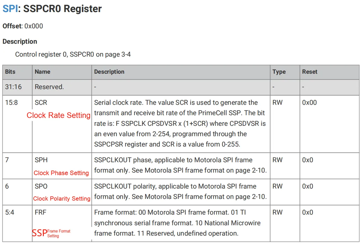
1.2.2 Registers Related to SPI Peripherals
The registers of SPI0 and SPI1 start from the base addresses SPI0_BASE 0x4003c000 and SPI1_BASE 0x40040000 respectively.
1.2.2.1 SPI Clock Frequency Division
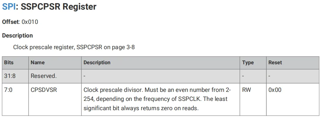
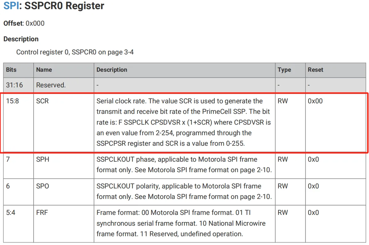
We can use the SSPCPSR register to adjust the clock division coefficient of SSPCLK, and by programming the SSPCR0 control register, we can further divide the divided clock by a factor of 1 to 256 to generate the serial output clock SSPCLKOUT.
The frequency of the SSPCLKOUT serial output clock is determined by the following formula:
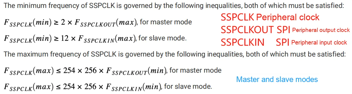
When setting the frequency of the serial output clock SSPCLKOUT, the following constraints shall be noted:
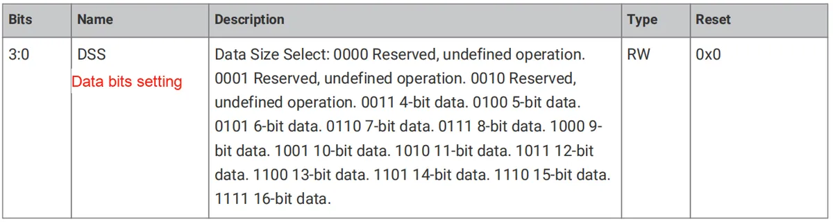
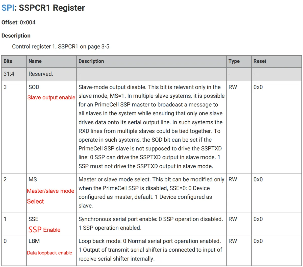
1.2.2.2 SPI Communication Parameter Setting
We can set the relevant parameters for SPI communication by using the control registers SSPCR0 and SSPCR1:
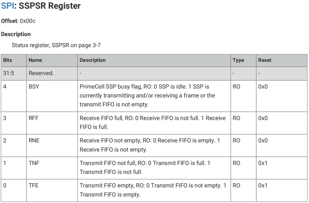
1.2.2.3 FIFO Memory Configuration and Status Access
The status of the FIFO memory can be obtained by accessing the SSPSR register:
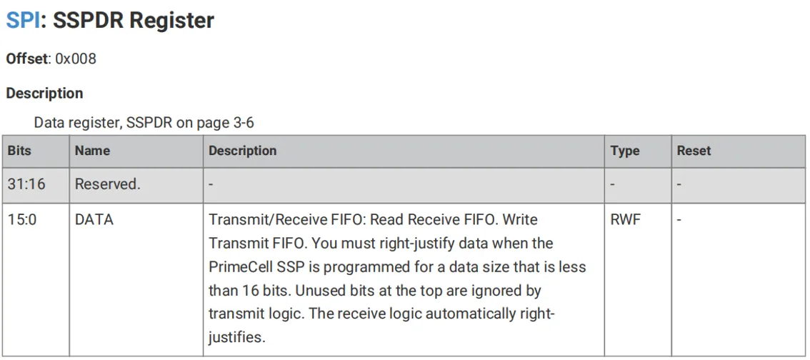
FIFO data can be read or FIFO data transmission can be controlled by accessing the SSPDR register:
1.2.2.4 SPI Interrupt Configuration
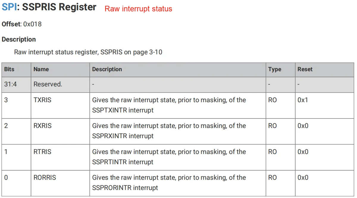
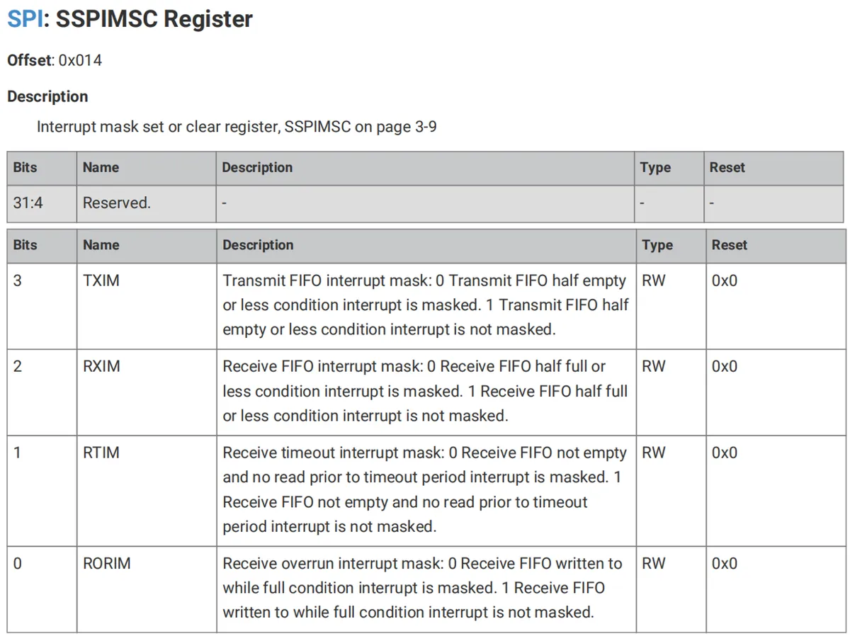
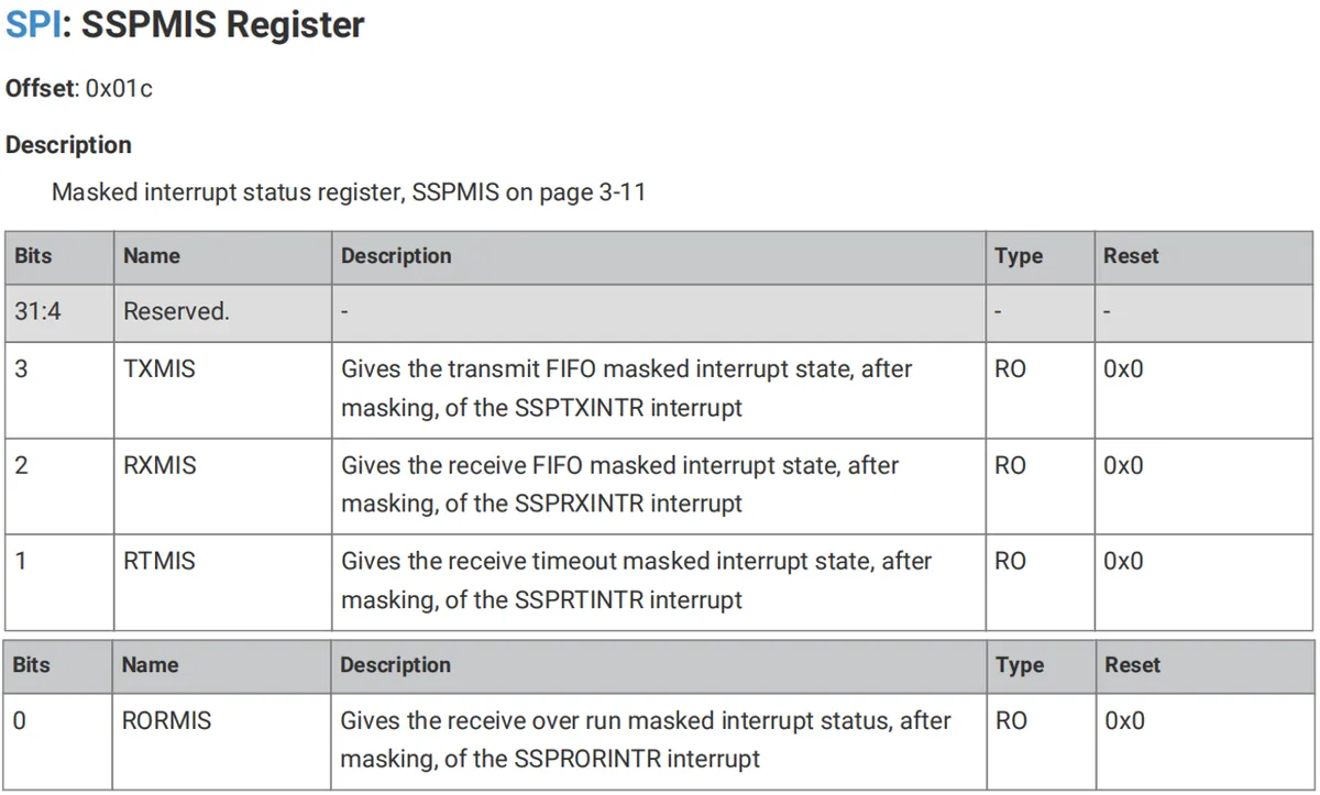
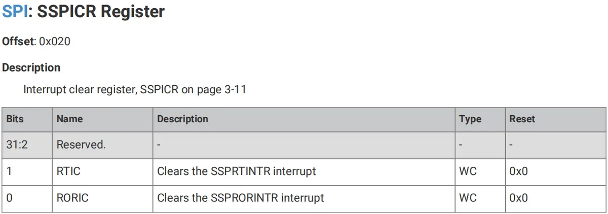
SPI interrupt-related settings can be adjusted by configuring the SSPIMSC, SSPRIS, SSPMIS, and SSPICR registers:
Obtain the raw peripheral interrupt status by accessing SSPRIS:
Set or read the interrupt mask by accessing the SSPIMSC register:
Obtain the masked interrupt status by accessing the SSPMIS register:
Clear the interrupt by accessing the SSPICR register:
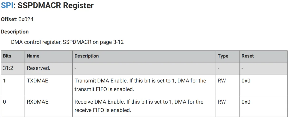
1.2.2.5 DMA Controller
Enable or disable the DMA for data reception or transmission by accessing the SSPDMACR register:
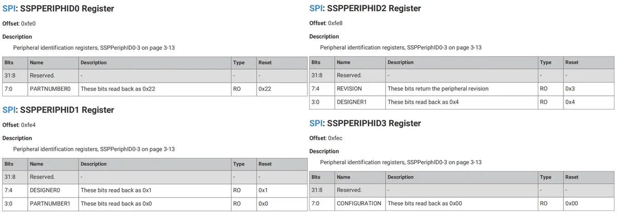
1.2.2.6 Peripheral Identification Register
Peripheral identification registers provide the standard information required for all components compliant with the generic ID register specification. They identify peripherals within a specific namespace. A set of peripheral ID registers consists of eight registers.
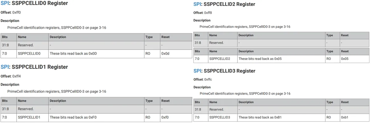
1.2.2.7 PrimeCell Identification Register
The PrimeCell identification registers are four 8-bit registers spanning the address locations 0xFF0 to 0xFFC; they can be regarded as a 32-bit register, and these registers can be used as a standard cross-peripheral identification system.
1.3 Overview of SPI for Raspberry Pi Pico
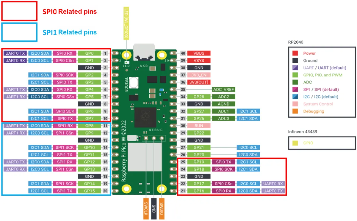
The RP2040 has two separate and identical SPI peripherals: SPI0 and SPI1, each of which supports the following functions:
Master or Slave Mode
16-bit Tx FIFO memory and 16-bit Rx FIFO memory with a depth of 8 bytes
Interrupts related to FIFO or indicating error conditions
from the DMA driver
Programmable Clock Rate
The programmable data size ranges from 4 to 16 bits
2. Software Control Method
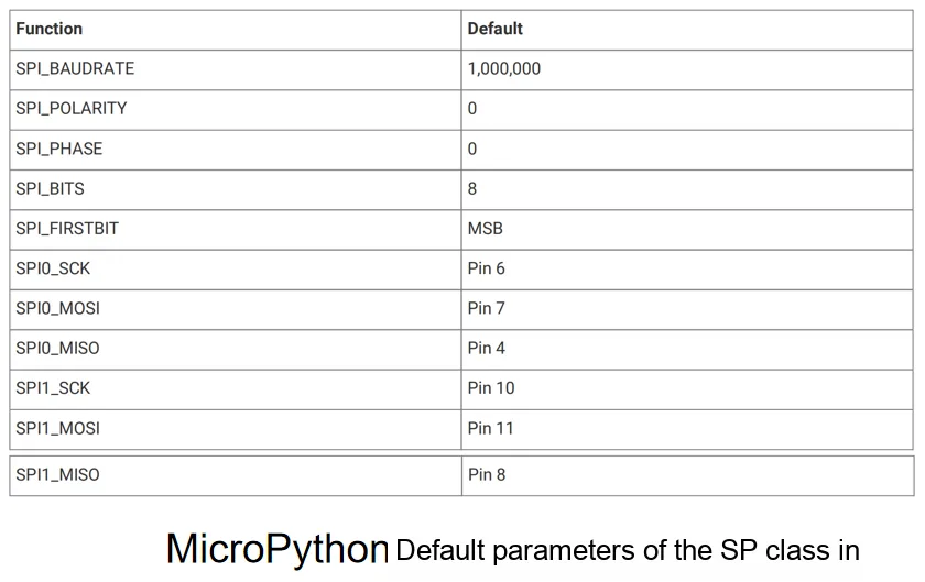
We can use the machine.SPI class to control the SPI hardware peripheral for data transmission with external devices, and we can also use the machine.SoftSPI class to generate a software-emulated I2C for data transmission with external devices. The differences between software SPI and hardware SPI are as follows:
SPI Type
Principle
Operating Speed
Portability
hardware SPI
Control the SPI peripheral of the Raspberry Pi Pico to implement the communication function
Fast
It's not that great; the SPI peripheral interface requires specific pins.
Software SPI
Communication functions are implemented by simulating SPI timing through GPIO control.
Slow
High, any pin can be used as an SPI interface
2.1 Constructor method of the machine.SPI class
The constructor of the machine.SPI class is as follows:
class machine.SPI(id, ...)
Construct an SPI object with the given parameters
The meanings of the parameters are as follows:
id - identifies a specific SPI peripheral; can be set to 0 or 1 on Raspberry Pi Pico
Without additional parameters, the SPI object is created but not initialized; if the extra parameters in the initialization method are provided, the initialization will be completed.
2.2 machine.SoftSPI Class Constructor
The constructor of the machine.SoftSPI class is as follows:
class machine.SPI(baudrate=500000, *, polarity=0, phase=0, bits=8, firstbit=MSB, sck=None, mosi=None, miso=None)
Construct a software SPI object with the given parameters
The parameters are defined as follows:
baud rate - SCK clock rate
polarity - clock polarity, selectable options:
0 - SCLK is at low level when idle
1 - SCLK is at a high level when idle
Phase - Clock phase, options available:
0 - Sampling is performed on the odd edges of SCLK
1 - Sampling is performed on the even edges of SCLK
bits - the number of bits of valid data transmitted per time; 8-bit data is a parameter supported by all hardware
firstbit - Select whether to use big-endian or little-endian, available options:
SoftSPI.MSB - Set the first bit as the most significant bit
SoftSPI.LSB - Set the first bit as the least significant bit
sck - Pass in a Pin object as the pin for SCLK
mosi - Pass in a Pin object as the MOSI pin
miso - Pass in a Pin object as the MISO pin
2.3 Other Methods of the SPI Class
The machine.SPI class and machine.SoftSPI class can implement I2C communication using the following methods:
Initialize the SPI bus with the given parameters; the initialization method is as follows:
baud rate - SCK clock rate
polarity - clock polarity, selectable options:
0 - SCLK is at low level when idle
1 - SCLK is at high level when idle
Phase - clock phase, optional:
0 - Sampling is performed on the odd edges of SCLK
1 - Sample on the even edges of SCLK
bits - the number of bits of valid data transmitted per time; 8-bit data is a parameter supported by all hardware
firstbit - Select whether to use big-endian or little-endian, available options:
SoftSPI.MSB - Set the first bit as the most significant bit
SoftSPI.LSB - Set the first bit as the least significant bit
sck - Pass in a Pin object as the pin for SCLK
mosi - Pass in a Pin object as the MOSI pin
miso - Pass in a Pin object as the MISO pin
pins - Tuple of Pin instances corresponding to SCLK, MOSI, and MISO
SPI.deinit()
Disable the SPI bus
SPI.read(nbytes, write=0)
Reads nbytes bytes, and continuously writes the specified single byte at the same time; the default value of write is 0x00, and returns a bytes object containing the read data.
SPI.readinto(buf, write=0)
Reads nbytes bytes, stores them in the buf buffer, and continuously writes the specified single byte; the default value for write is 0x00, with no return value.
SPI.write(buf)
Writes the buf containing the bytes to be sent, with no return value
SPI.write_readinto
(write_buf, read_buf)
Writes to write_buf containing the bytes to be sent, and simultaneously reads len (read_buf) bytes of data and stores them in read_buf; no return value.
According to https://github.com/micropython/micropython/issues/3700 and other references, we found that the machine.SPI class in MicroPython only supports master mode and cannot run as a slave device.
3. Application Examples
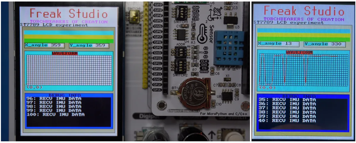
3.1 Experiment of Controlling LCD Screen to Display Gyroscope Data via SPI
3.1.1 Introduction to LCD Screens
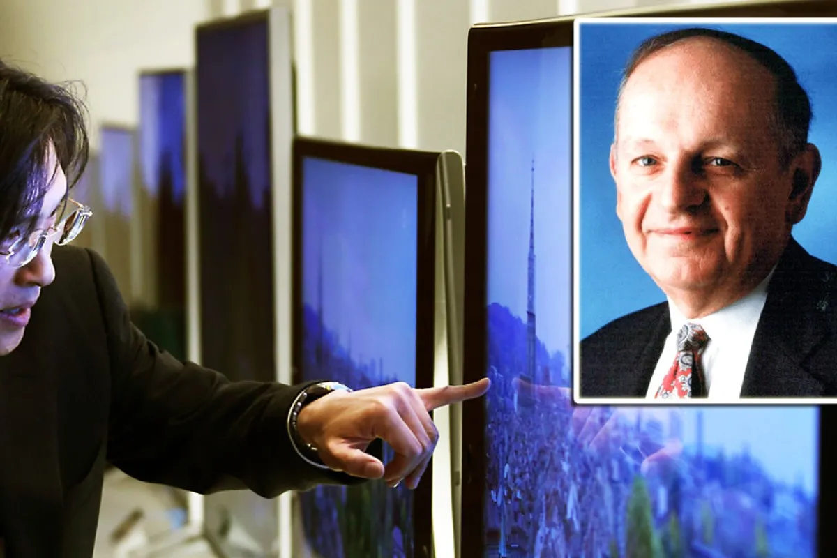
LCD (Liquid Crystal Display), short for liquid crystal display, the first LCD screen was invented in 1968 by George Heilmeier of the US Radio Corporation (RCA), which required an operating temperature of approximately 80°C. Since then, the dream of a flat-panel TV that hangs on the wall like a painting has been born.
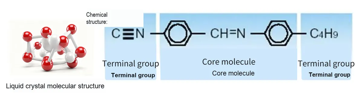
LCD realizes the display function with the help of liquid crystal, which is a special substance between solid and liquid. As an organic compound, liquid crystal is in a liquid state under normal conditions, but its molecular arrangement is as regular as that of solid crystals, hence the name liquid crystal.
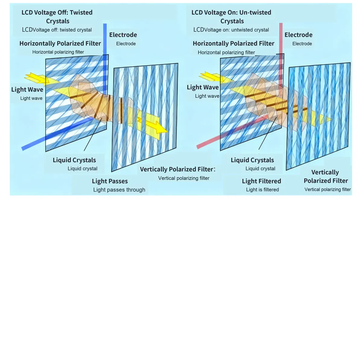
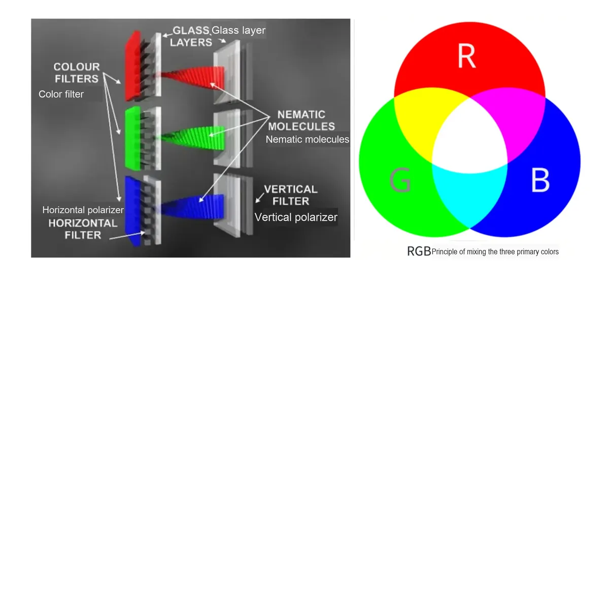
When an electric field is applied to liquid crystal, its molecular arrangement will change, thereby altering the propagation of light. Combined with a polarizer, liquid crystal can control the transmittance of light. When further paired with a color filter, adjusting the magnitude of the voltage applied to the liquid crystal will change the light transmission of a specific color.
Based on this principle, a display structure with controllable output intensities of red, green and blue light is fabricated. Three such display structures form one display unit, and by controlling the intensities of red, green and blue, this unit can produce mixed outputs of different colors. Such a display unit is called a pixel, which means a pixel contains three display units of R, G and B, and various colors can be mixed by adjusting the proportion of the three colors.
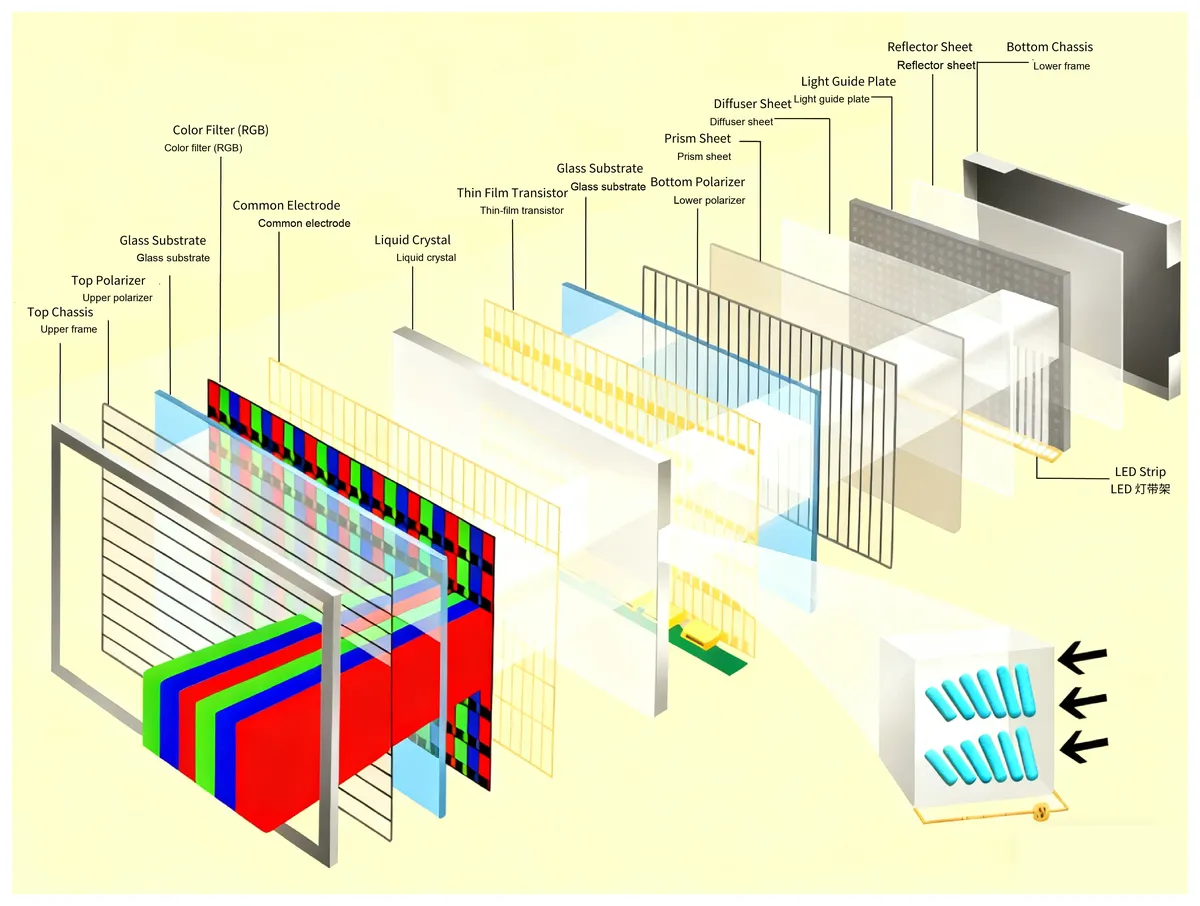
For TFT LCD screens, they consist of five components: backlight unit, polarizer, liquid crystal display panel, integrated circuit, and flexible printed circuit. Since liquid crystals do not emit light, a backlight is required to provide a light source; the function of the polarizer is to convert unpolarized natural light into polarized light and control which light patterns can pass through the liquid crystal panel; the integrated circuit is used to adjust and control parameters such as the phase, peak value, and frequency of the potential signals on the transparent electrodes to establish a driving electric field, ultimately realizing the information display on the screen; the flexible printed circuit board is used to connect the liquid crystal panel and output the interface that the motherboard needs to match;A liquid crystal panel consists of a color filter (CF) and a thin-film transistor array (TFT array). It is a liquid crystal package embedded between two glass substrates, which applies pixel voltages to the liquid crystal to achieve the desired color display.
Figure 3-5 Schematic of TFT LCD screen structure
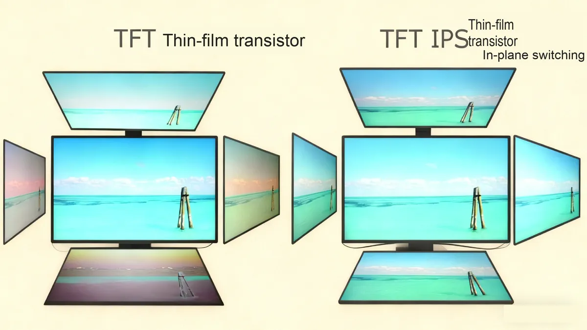
LCD liquid crystal displays feature the advantages of low power consumption, small size, large information carrying capacity and eye-friendliness. At present, LCD screens are widely used in consumer electronics, medical devices, wearable devices, automotive electronics and other fields. The basic parameters of an LCD monitor include pixels, resolution, color depth, monitor size, etc.Currently, the widely used type of LCD is IPS TFT LCD, commonly known as "Super TFT". As a technology upgraded from TFT, it adjusts the arrangement of liquid crystal molecules. Compared with ordinary TFT screens, it boasts advantages such as a wide viewing angle, accurate color reproduction, no watermarks when touched, and eco-friendly power saving.
Schematic comparison of viewing angles of TFT and TFT IPS LCD screens
3.1.2 Introduction to ST7789 Chip
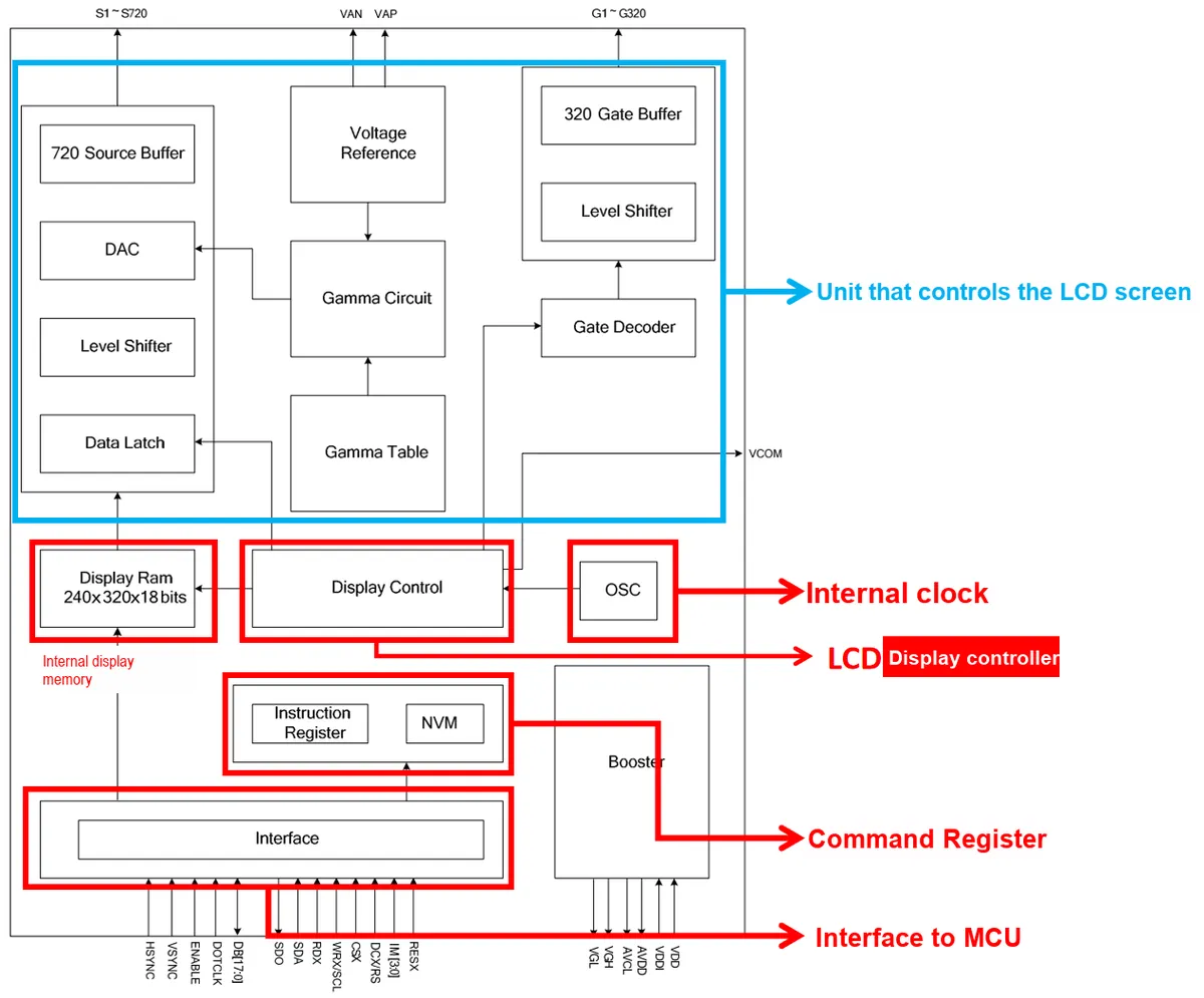
The ST7789 is a commonly used control chip for TFT LCD screens. Devices supporting this chip can be directly connected to an external microprocessor, and it is compatible with 8-bit/9-bit/16-bit/18-bit parallel interfaces as well as 3-wire SPI and 4-wire SPI serial interfaces. It supports LCD screens with a maximum resolution of 240x320, can perform read/write operations on display data RAM, and features the advantages of low power consumption, simple hardware connection, and diverse interfaces.
The following is the block diagram of the ST7789 unit:
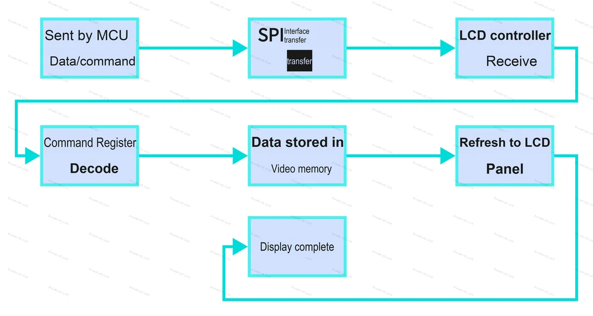
The workflow of the ST7789 controlling the LCD screen display can be simplified as follows:
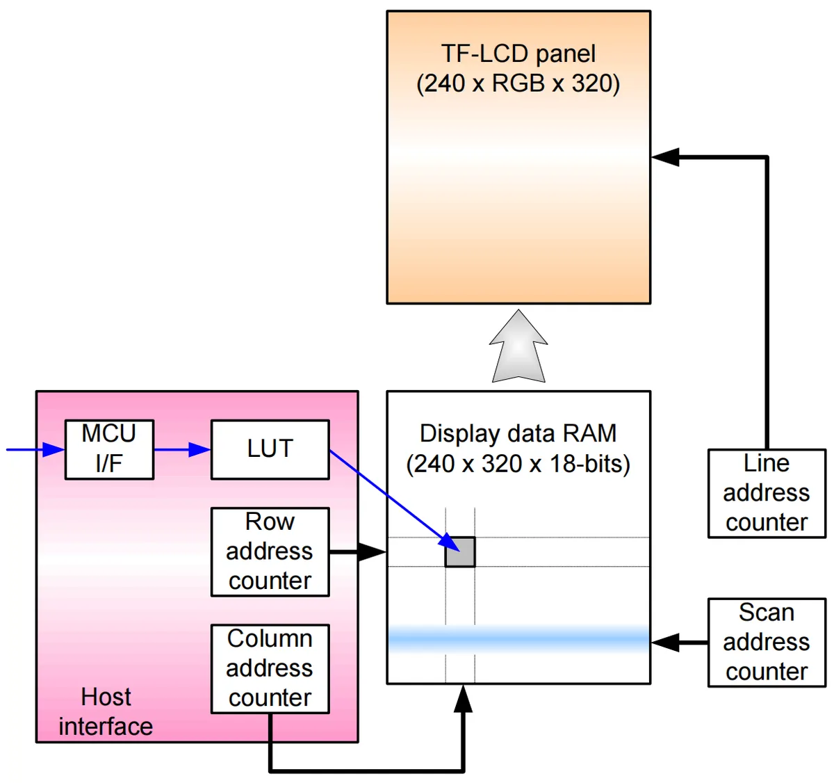
The liquid crystal controller communicates with the single-chip microcomputer via the SPI interface. The single-chip microcomputer sends the data to be displayed and the corresponding control instructions to the liquid crystal controller through the exported SPI interface, and the instruction register decodes the received instructions and data. The data will be stored in the internal display memory of the ST7789, and then the liquid crystal controller executes the corresponding instructions to continuously refresh the content of the display memory to the corresponding position of the liquid crystal panel, so as to complete the display function of the LCD screen.
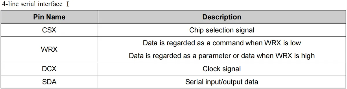
When we use 4-wire SPI to control the LCD screen, the communication signal definitions of the ST7789 are as follows:
The meanings of the respective signal lines are as follows:
CSX - Chip Select Pin
WRX - When WRX is at high level, it indicates data writing; when WRX is at low level, it indicates command writing
DCX - Clock Signal
SDA - Serial data input and output are combined into one, meaning MISO and MOSI share the same line
The LCD screen also supports 3-wire SPI protocol for control:
Three-wire SPI and four-wire SPI that are easily confused
For most commercially available LCD screens that use the SPI protocol, their SPI interface is not the standard 4-wire SPI (with four signal lines: CS, MOSI, MISO, CLK), but a dedicated SPI interface. In most cases of such 4-wire SPI implementations, the MOSI and MISO lines are combined into a single SDA signal line, or the MISO line is not utilized at all.
And it should be noted that the difference between 4-wire SPI and 3-wire SPI for LCD screens using the SPI protocol is as follows: 4-wire SPI has a WRX signal line to indicate whether the master is sending a control command or data selection, while 3-wire SPI does not have a WRX signal line, but uses an extra bit in the data to indicate whether it is a command or data. Therefore, the common effective data bit of 3-wire SPI is 9 bits, which is one more data bit than that of 4-wire SPI, rather than what is described in most textbooks that 3-wire SPI has no MISO, or MISO is collinear with MOSI.
Some LCD screens that use the 4-wire SPI protocol adopt separate MOSI/SDI and MISO/SDO signal lines, strictly speaking, this type of SPI protocol should be referred to as 5-wire SPI, which consists of five signal lines: CS, MOSI, MISO, WRX and SCLK.
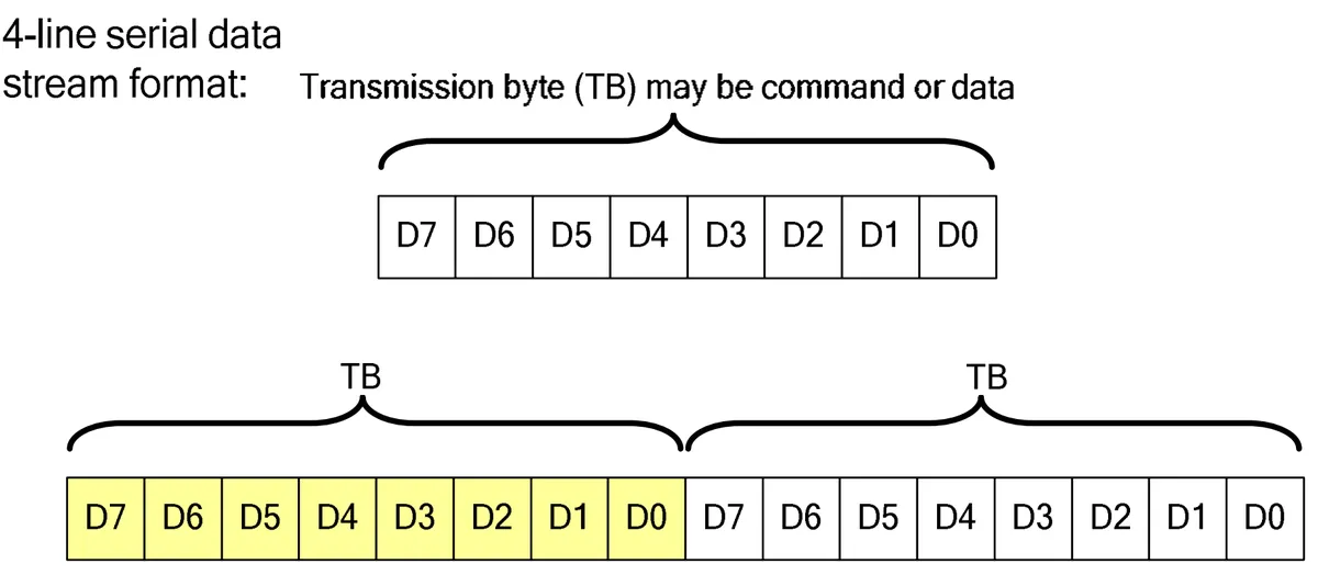
The data format is as follows, in MSB big-endian order:
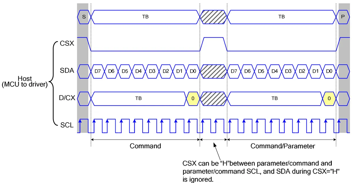
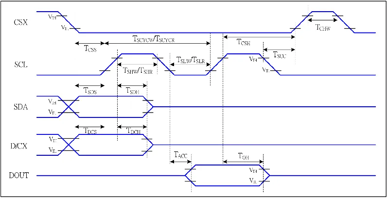
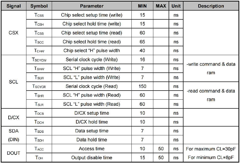
The write timing when the number of valid data bits is 8 is as follows:
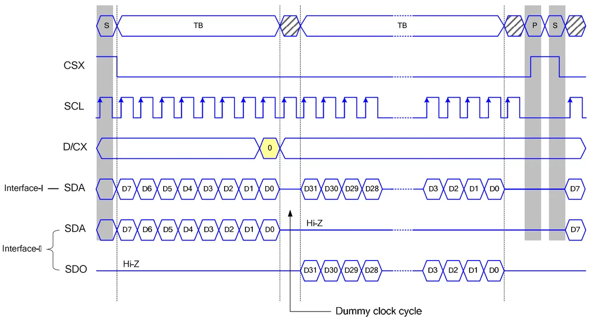
The read timing when the number of valid data bits is 8 is as follows:
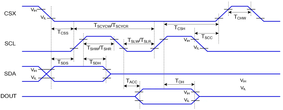
The timing sequence of the 4-wire SPI protocol is as follows:
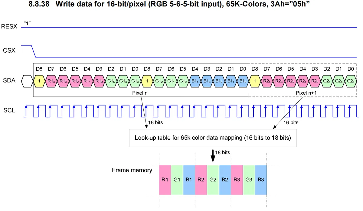
ST7789 supports input color formats of 12-bit, 16-bit and 18-bit per pixel, namely three color formats: RGB444, RGB565 and RGB666. Here we use RGB565, the most commonly used RGB color format, which stores pixel information in 2 bytes (16 bits, capable of representing 2^16 = 65536 colors, i. e., 65K), where the R channel occupies 5 bits, the G channel occupies 6 bits, and the B channel occupies 5 bits.
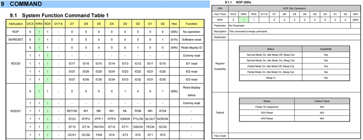
Meanwhile, the ST7789 chip integrates a large number of internal registers for controlling various parameters, including sleep settings, color format, screen orientation, RGB order, color inversion, display mode, gamma correction, display on/off and other parameter configurations, which can be referred to in the official datasheet of the ST7789.
Here, given the large number of internal registers and diverse instructions of the ST7789, we will not conduct an in-depth discussion on it. In the next section, we directly provide the corresponding driver code for you to call directly. When using MicroPython to control the display of the LCD screen, the focus should be on interface rendering rather than low-level register operations. Therefore, we do not elaborate on the ST7789-related content at length here, and readers only need to have a basic understanding of it.
3.1.3 Experiment on Controlling LCD Screen Display
3.1.3.1 Experimental Preparation
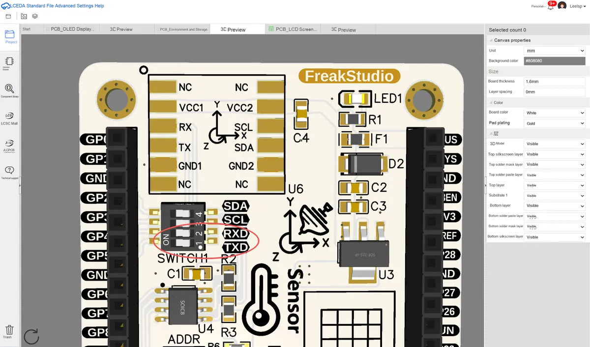
Here, we need to Fengya No.1 Board - Universal Compatible Expansion Board inserted into the Fengya No.1 Board - LCD screen human-machine interaction board , and then the Fengya No.1 Board - Environment and Storage Acquisition Board inserted into the Fengya No.1 Board - Universal Compatibility Expansion Board , while opening the Fengya No.1 Board - Environment and Storage Acquisition Board on the SWITCH1 DIP switch RXD and TXD options, the physical connection diagram is shown below:
The meaning of the signal lines led out from the LCD screen and their pin connections to the Raspberry Pi Pico are as follows:
Pin Name
Pin Functions
Connect the Pico pins
VCC/VDD
The LCD screen is powered by 3.3V.
3V3_OUT
GND
Power Ground
GND
CS
Chip select pin, active low enable
GP6
RST
Reset terminal, enabled at low level
GP8
DC/WRX
Data/Command Select Pin:
Low level: Send command
High level: Send register parameters or display data
GP7
SDA/SDI
SPI data input terminal
GP11
SCL
SPI clock signal terminal
GP10
BLK/BL
The backlight control terminal supports control via PWM or high/low level signals
GP9
The connection between the gyroscope and the Raspberry Pi Pico pins is as follows:
Pin Name
Pin Functions
Connect the Pico pins
VCC
The serial gyroscope is powered by 5V.
+5V
RX
Serial Port Gyroscope Receiver - Raspberry Pi Pico Serial Port Transmitter
GP4
TX
Serial port gyroscope transmitter - Raspberry Pi Pico serial port receiver
GP5
GND
Power Ground
GND
Fengya No. 1 Board - Notes for Use of LCD Screen Human-Machine Interaction Board
Please note that the pin headers matched with the long female header of the Elegant Style No. 1 Board - Universal Compatible Expansion Board are longer than conventional pin headers. When connecting, there is no need to fully insert the pin headers into the female header of the Elegant Style No. 1 Board - LCD Screen Human-Machine Interaction Board. Forcible full insertion may cause abnormal pin contact or mechanical interference due to the excessively long pin headers, which will instead affect the stability of the electrical connection.
Here’s a practical tip to check whether the connection is normal: after insertion, observe the power indicator lights on the two boards — if the brightness of the power indicator on the LCD screen human-machine interaction board is basically consistent with that on the universal compatible expansion board, it indicates that the insertion depth is appropriate and the electrical connection is normal; if there is a significant difference in brightness between the two (e. g., one is too dim or does not light up), it may be caused by poor contact due to too deep or too shallow insertion, and you need to adjust the insertion depth appropriately before trying again.
All the code for the following experiments is open-source in the resource package we provide, and can be found in the folder elegance-devkit v1\Demo\20 SPI_LCD_ShowIMUData.
3.1.3.2 Explanation of the Code for the ST7789 Driver Section
For this part of the code, we referred to the open-source project st7789py_mpy developed by russhughes: https://github.com/russhughes/st7789py_mpy/blob/master/lib/st7789py.py
This open-source code provides a complete interface for controlling and operating the ST7789 LCD screen, which can be used to develop various embedded projects based on ST7789 LCDs. Here, since the tutorial focuses on applying MicroPython for application-layer development of embedded devices and is limited by length, readers can refer to the details and procedures related to ST7789 command transmission on their own; we have added detailed comments to the code in accordance with the ST7789 datasheet.
Next, let's take a look at the code. First, the relevant modules are imported in the project:
# Python env   : MicroPython v1.23.0
# -*- coding: utf-8 -*-
# @Time    : 2024/7/7 AM 12:02
# @Author  : Li Qingshui
# @File    : st7789.py
# @Description : Class implementation of the LCD screen driver chip ST7789
# Reference: russhughes st7789py_mpy: https://github.com/russhughes/st7789py_mpy/blob/master/lib/st7789py.py

# ======================================== Import Modules ========================================

# Hardware-related modules
from micropython import const
import machine
import micropython
# Time-related modules
import time
# Module related to mathematical calculations
from math import sin, cos
# Module related to packing and unpacking
import struct
Next, the code defines a series of constants and global variables for storing the commands and data of the ST7789:
# ======================================== Global Variables ============================================

# ST7789 command list

# Software reset command, used to initialize the LCD
_ST7789_SWRESET = b"\x01"
# Enter sleep mode command
_ST7789_SLPIN   = b"\x10"
# Exit sleep mode command
_ST7789_SLPOUT  = b"\x11"
# Normal mode command
_ST7789_NORON   = b"\x13"
# Turn off screen inversion command
_ST7789_INVOFF  = b"\x20"
# Turn on screen inversion command
_ST7789_INVON   = b"\x21"
# Turn off screen display command
_ST7789_DISPOFF = b"\x28"
# Turn on screen display command
_ST7789_DISPON  = b"\x29"
# Set column address range command
_ST7789_CASET   = b"\x2a"
# Set row address range command
_ST7789_RASET   = b"\x2b"
# Write memory command
_ST7789_RAMWR   = b"\x2c"
# Set vertical scan direction command
_ST7789_VSCRDEF = b"\x33"
# Set color mode command
_ST7789_COLMOD  = b"\x3a"
# Set memory access control command
_ST7789_MADCTL  = b"\x36"
# Set vertical offset command
_ST7789_VSCSAD  = b"\x37"
# Set memory control command
_ST7789_RAMCTL  = b"\xb0"

# MADCTL bit definitions
_ST7789_MADCTL_MY   = const(0x80)  # Specifies that pixel data is read from bottom to top
_ST7789_MADCTL_MX   = const(0x40)  # Specifies that pixel data is read from right to left
_ST7789_MADCTL_MV   = const(0x20)  # Specifies that pixel data scrolls from top to bottom
_ST7789_MADCTL_ML   = const(0x10)  # Specifies that pixel data scrolls from left to right
_ST7789_MADCTL_BGR  = const(0x08)  # Specifies that the pixel data order is BGR
_ST7789_MADCTL_MH   = const(0x04)  # Reserved bit, unused
_ST7789_MADCTL_RGB  = const(0x00)  # Specifies that the pixel data order is RGB

# Constant definitions
RGB = const(0x00)  # Specifies that the pixel data order is RGB
BGR = const(0x08)  # Specifies that the pixel data order is BGR

# Color mode definitions
_COLOR_MODE_65K     = const(0x50)  # 65K color mode
_COLOR_MODE_262K    = const(0x60)  # 262K color mode
_COLOR_MODE_12BIT   = const(0x03)  # 12-bit color mode
_COLOR_MODE_16BIT   = const(0x05)  # 16-bit color mode
_COLOR_MODE_18BIT   = const(0x06)  # 18-bit color mode
_COLOR_MODE_16M     = const(0x07)  # 16 million color mode

# Color definitions
BLACK   = const(0x0000)  # Black
BLUE    = const(0x001F)  # Blue
RED     = const(0xF800)  # Red
GREEN   = const(0x07E0)  # Green
CYAN    = const(0x07FF)  # Cyan
MAGENTA = const(0xF81F)  # Magenta
YELLOW  = const(0xFFE0)  # Yellow
WHITE   = const(0xFFFF)  # White

# Encoded pixel format definitions
_ENCODE_PIXEL = const(">H")             # Big-endian byte order, two bytes represent one pixel value
_ENCODE_PIXEL_SWAPPED = const("<H")     # Little-endian byte order, two bytes represent one pixel value
_ENCODE_POS = const(">HH")              # Big-endian byte order, two bytes represent the x and y coordinates
_ENCODE_POS_16 = const("<HH")           # Little-endian byte order, two bytes represent the x and y coordinates

# Constants for setting the buffer size and number of bits

# Buffer size of at least 128 bytes, for 8-bit-wide fonts
# Buffer size of at least 256 bytes, for 16-bit-wide fonts
_BUFFER_SIZE = const(257)

# Bit definitions
_BIT7 = const(0x80)  # Bit 7
_BIT6 = const(0x40)  # Bit 6
_BIT5 = const(0x20)  # Bit 5
_BIT4 = const(0x10)  # Bit 4
_BIT3 = const(0x08)  # Bit 3
_BIT2 = const(0x04)  # Bit 2
_BIT1 = const(0x02)  # Bit 1
_BIT0 = const(0x01)  # Bit 0

# Dictionary that stores the rotation information for each screen size
_DISPLAY_240x320 = (
    (0x00, 240, 320, 0, 0, False),
    (0x60, 320, 240, 0, 0, False),
    (0xc0, 240, 320, 0, 0, False),
    (0xa0, 320, 240, 0, 0, False))

_DISPLAY_240x240 = (
    (0x00, 240, 240,  0,  0, False),
    (0x60, 240, 240,  0,  0, False),
    (0xc0, 240, 240,  0, 80, False),
    (0xa0, 240, 240, 80,  0, False))

_DISPLAY_135x240 = (
    (0x00, 135, 240, 52, 40, False),
    (0x60, 240, 135, 40, 53, False),
    (0xc0, 135, 240, 53, 40, False),
    (0xa0, 240, 135, 40, 52, False))

_DISPLAY_128x128 = (
    (0x00, 128, 128, 2, 1, False),
    (0x60, 128, 128, 1, 2, False),
    (0xc0, 128, 128, 2, 1, False),
    (0xa0, 128, 128, 1, 2, False))

# Index into the rotation table
_WIDTH = const(0)
_HEIGHT = const(1)
_XSTART = const(2)
_YSTART = const(3)
_NEEDS_SWAP = const(4)

# Supported displays (physical width, physical height, rotation table)
_SUPPORTED_DISPLAYS = (
    (240, 320, _DISPLAY_240x320),
    (240, 240, _DISPLAY_240x240),
    (135, 240, _DISPLAY_135x240),
    (128, 128, _DISPLAY_128x128))

# Tuple of commands to send during initialization, in the format command, data, delay in ms
_ST7789_INIT_CMDS = (
    ( b'\x11', b'\x00', 120),               # Exit sleep mode
    ( b'\x13', b'\x00', 0),                 # Turn on the display
    # Parameter 0a means the row scan direction is bottom to top, 82 means the column scan direction is right to left
    ( b'\xb6', b'\x0a\x82', 0),             # Set display function control
    # Parameter 55 means the weights of red, green and blue are 5, 6 and 5 respectively
    ( b'\x3a', b'\x55', 10),                # Set the pixel format to 16 bits per pixel (RGB565)
    # Parameter 0c means the start row, 0c means the end row, 00 means the start column, 33 means the end column
    ( b'\xb2', b'\x0c\x0c\x00\x33\x33', 0), # Set gate control
    # Parameter 35 means the VGS voltage
    ( b'\xb7', b'\x35', 0),                 # Set gate control
    # Parameter 28 means the VCOM voltage
    ( b'\xbb', b'\x28', 0),                 # Set VCOMS setting
    ( b'\xc0', b'\x0c', 0),                 # Set power control 1
    ( b'\xc2', b'\x01\xff', 0),             # Set power control 2
    ( b'\xc3', b'\x10', 0),                 # Set power control 3
    ( b'\xc4', b'\x20', 0),                 # Set power control 4
    ( b'\xc6', b'\x0f', 0),                 # Set VCOM control 1
    ( b'\xd0', b'\xa4\xa1', 0),             # Set power control A
    # Set the positive polarity gamma curve, used to adjust the brightness of red, green and blue
    ( b'\xe0', b'\xd0\x00\x02\x07\x0a\x28\x32\x44\x42\x06\x0e\x12\x14\x17', 0),
    # Set the negative polarity gamma curve, used to adjust the brightness of red, green and blue
    ( b'\xe1', b'\xd0\x00\x02\x07\x0a\x28\x31\x54\x47\x0e\x1c\x17\x1b\x1e', 0),
    ( b'\x21', b'\x00', 0),                 # Enable display inversion
    ( b'\x29', b'\x00', 120)                # Turn on the display, wait 120 ms
)
Next, the code defines the color565 function, which is used to convert the red, green, and blue channel values (0-255) into 16-bit BGR565 encoding. However, after practical application, it is found that this part of the function cannot operate normally. When using the LCD screen, you can directly use the color BGR565 encoding constants defined in our LCD class.
# ======================================== Functions ============================================

def color565(red: int, green: int = 0, blue: int = 0) -> int:
    """
    Convert red, green and blue channel values (0-255) to a 16-bit BGR565 encoding.

    Args:
        red (int): Red channel value, range 0 to 255 (MicroPython built-in type: int).
        green (int, optional): Green channel value, range 0 to 255, default 0 (MicroPython built-in type: int).
        blue (int, optional): Blue channel value, range 0 to 255, default 0 (MicroPython built-in type: int).

    Returns:
        int: BGR565 encoded value of the corresponding color (16-bit integer, MicroPython built-in type: int).

    Raises:
        ValueError: Raised if any color channel value is not in the range 0 to 255.
    """
    if isinstance(red, (tuple, list)):
        # If a tuple or list is passed in, take the first three elements as the red, green and blue values
        red, green, blue = red[:3]
    # Limit the BGR values to the range 0-255
    r = max(0, min(red, 255))
    g = max(0, min(green, 255))
    b = max(0, min(blue, 255))
    # Calculate the RGB565 encoding; the formula for BGR565 encoding is as follows:
    # R = (Red & 0b11111000) >> 3
    # G = (Green & 0b11111100) >> 2
    # B = (Blue & 0b11111000) >> 3
    # Combine the new BGR values into a 16-bit 565 encoding
    return (b & 0x1F) << 11 | (g & 0x3F) << 5 | (r & 0x1F)
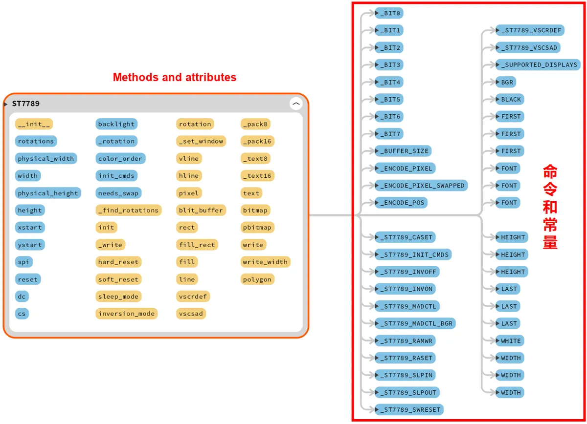
Next, a class named ST7789 is defined, which includes methods such as initialization, data writing, color mode setting, text drawing, and graphics rendering.
In the class's initialization method, it will check whether the screen size and rotation angle are supported, and then find the corresponding rotation information based on the screen size and rotation angle. Next, initialize the control pins, and perform hard reset and soft reset operations. After that, initialize the screen according to the provided parameters, including setting display function control, pixel format, gating control, etc. Here, the static private method _find_rotations of the class is defined to find the supported rotation information according to the screen size and rotation angle.
# ST7789 LCD screen controller chip class
class ST7789:
    """
    ST7789 driver class, encapsulating the low-level interface for communicating with ST7789-series display controllers and basic graphics/text drawing functions.

    This class directly operates the SPI and control pins (DC/RESET/CS/backlight), implementing the initialization sequence, register writes,
    window setting, and basic drawing operations such as pixels/rectangles/lines/polygons, and provides stable low-level support for higher-level UI classes (such as LCD).

    Attributes:
        spi (machine.SPI): SPI instance used to communicate with the display. (MicroPython built-in type: machine.SPI)
        dc (machine.Pin): Data/command select pin instance. (MicroPython built-in type: machine.Pin)
        reset (machine.Pin | None): Reset pin instance or None. (MicroPython built-in type: machine.Pin / None)
        cs (machine.Pin | None): Chip select pin instance or None. (MicroPython built-in type: machine.Pin / None)
        backlight (machine.Pin | None): Backlight pin instance or None. (MicroPython built-in type: machine.Pin / None)
        width (int): Current logical width (in pixels, changes with rotation). (MicroPython built-in type: int)
        height (int): Current logical height (in pixels, changes with rotation). (MicroPython built-in type: int)
        physical_width (int): Physical width of the screen (in pixels). (MicroPython built-in type: int)
        physical_height (int): Physical height of the screen (in pixels). (MicroPython built-in type: int)
        xstart (int): Column offset (MicroPython built-in type: int).
        ystart (int): Row offset (MicroPython built-in type: int).
        rotations (tuple): Supported rotation table (each entry contains MADCTL/width/height/xstart/ystart/needs_swap). (MicroPython built-in type: tuple)
        init_cmds (tuple): Command sequence used to initialize the display (command,data,delay_ms). (MicroPython built-in type: tuple)
        needs_swap (bool): Indicates whether the byte order needs to be swapped when writing pixels (MicroPython built-in type: bool).
        color_order (int): Pixel byte order flag (e.g. BGR/RGB constants). (MicroPython built-in type: int)
        _rotation (int): Current rotation index 0-3. (MicroPython built-in type: int)

    Methods:
        __init__(self, spi: machine.SPI, width: int, height: int,
                 reset: machine.Pin = None, dc: machine.Pin = None, cs: machine.Pin = None,
                 backlight: machine.Pin = None, rotation: int = 0,
                 color_order: int = BGR, custom_init: tuple = None, custom_rotations: tuple = None) -> None:
            Constructor; initializes pins/state, performs a hardware reset and initializes the display with init_cmds.
            Raises:
                ValueError: If the resolution is not supported or a required pin (e.g. dc) is missing.

        _find_rotations(width: int, height: int) -> tuple | None:
            Static method; looks up the supported rotations table by physical size, returns None if not found.

        init(self, commands: tuple) -> None:
            Send the initialization command sequence in order. Each item in commands has the format (command: bytes, data: bytes, delay_ms: int).

        _write(self, command: bytes = None, data: bytes = None) -> None:
            Low-level write: handles the CS/DC pins and sends command/data over SPI (command or data may be None).

        hard_reset(self) -> None:
            Hardware reset: performs the timing sequence using the reset pin (including the necessary delays) and releases CS at the end.

        soft_reset(self) -> None:
            Software reset: sends the SWRESET command and waits.

        sleep_mode(self, value: bool) -> None:
            Enter/exit sleep (SLPIN/SLPOUT); value=True means enter sleep.

        inversion_mode(self, value: bool) -> None:
            Turn display inversion on/off (INVON/INVOFF); value indicates whether to enable it.

        rotation(self, rotation: int) -> None:
            Apply a rotation index: updates MADCTL/width/height/xstart/ystart/needs_swap and writes MADCTL.

        _set_window(self, x0: int, y0: int, x1: int, y1: int) -> None:
            Restrict subsequent pixel writes to a rectangular area, writing addresses to CASET/RASET and sending RAMWR.

        pixel(self, x: int, y: int, color: int) -> None:
            Write a single pixel at (x,y), choosing the pixel byte order according to needs_swap.

        hline / vline / rect / fill_rect / fill (various shape drawing):
            Basic shape drawing methods; fill_rect writes in chunks using _BUFFER_SIZE to limit memory usage.

        blit_buffer(self, buffer: bytes | bytearray | memoryview, x: int, y: int, width: int, height: int) -> None:
            Write a pixel buffer already arranged in the current pixel byte order to the screen (supports bytes/bytearray/memoryview).

        line(self, x0: int, y0: int, x1: int, y1: int, color: int) -> None:
            Draw a line using the Bresenham algorithm.

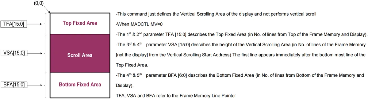
        vscrdef(self, tfa: int, vsa: int, bfa: int) -> None:
            Set the vertical scroll area (TFA/VSA/BFA); parameters are in pixels.

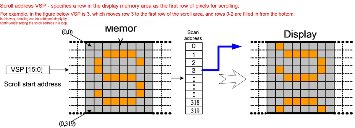
        vscsad(self, vssa: int) -> None:
            Set the vertical scroll start address (Vertical Scroll Start Address).

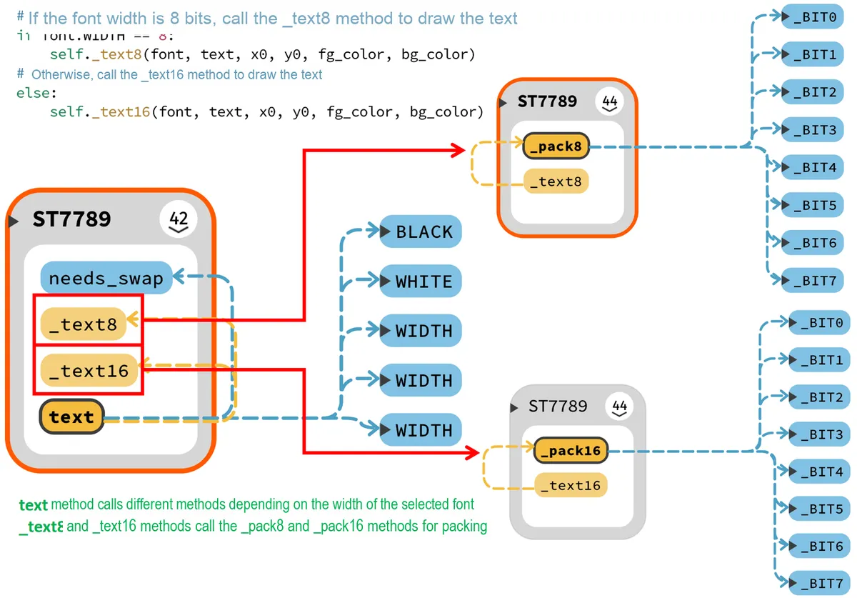
        _pack8 / _pack16 (viper optimized functions):
            High-performance internal packing functions, used to convert glyph data into a pixel buffer (used by _text8/_text16).
            **Important**: Due to limitations of @micropython.viper, `bytearray`, `bytes`, `memoryview` or return type annotations must not be used in the function signature,
            as these annotations cause a ViperTypeError. The return value type (e.g. returns bytearray) can be described in the docstring, but do not write it into the signature.

        _text8(self, font, text: str, x0: int, y0: int, fg_color: int, bg_color: int) -> None:
            Text drawing implementation based on 8-wide glyphs (calls _pack8 + blit_buffer).

        _text16(self, font, text: str, x0: int, y0: int, fg_color: int, bg_color: int) -> None:
            Text drawing implementation based on 16-wide glyphs (calls _pack16 + blit_buffer).

        text(self, font, text: str, x0: int, y0: int, color: int = WHITE, background: int = BLACK) -> None:
            High-level text interface: automatically switches between _text8/_text16 according to font.WIDTH, and adjusts the byte order when necessary.

        bitmap / pbitmap:
            Bitmap drawing methods: bitmap packs the entire bitmap at once (uses more memory), pbitmap draws row by row to save memory.

        write(self, font, string: str, x: int, y: int, fg: int = WHITE, bg: int = BLACK) -> None:
            Write character by character using a converted TrueType-style font (supports variable-width fonts and fonts with offset tables).

        write_width(self, font, string: str) -> int:
            Calculate and return the pixel width required to draw a string (used for layout/alignment).

        polygon(self, points: list, x: int, y: int, color: int, angle: float = 0.0, center_x: int = 0, center_y: int = 0) -> None:
            Draw a closed polygon, with optional rotation; raises ValueError when points has fewer than 3 items.

    Usage Notes:
        - For internal functions decorated with @micropython.viper (such as _pack8/_pack16), do not use complex type annotations in the signature,
          it is recommended to use annotations only for integer parameters (int), and describe the other parameters and the return type in the docstring.
        - All externally visible interfaces are documented using common MicroPython built-in types (int/bytes/bytearray/memoryview/str/list/tuple/machine.Pin/machine.SPI).
        - On memory-constrained devices, prefer row-by-row or chunked drawing (pbitmap / fill_rect chunks) to avoid allocating a huge buffer at once.
        - If a Viper compile error occurs (e.g. ViperTypeError), check the annotations of the decorated function and remove the unsupported type annotations.
    """

    def __init__(self, spi: 'machine.SPI', width: int, height: int, reset: 'machine.Pin' = None,
                 dc: 'machine.Pin' = None, cs: 'machine.Pin' = None, backlight: 'machine.Pin' = None,
                 rotation: int = 0, color_order: int = BGR,
                 custom_init: tuple = None, custom_rotations: tuple = None) -> None:
        """
        Initialization method of ST7789.

        Args:
            spi (machine.SPI): Configured SPI instance used to communicate with the display (MicroPython built-in type: machine.SPI).
            width (int): Physical width of the screen (in pixels). (MicroPython built-in type: int)
            height (int): Physical height of the screen (in pixels). (MicroPython built-in type: int)
            reset (machine.Pin, optional): Reset pin instance; pass None if not needed. Default None. (MicroPython built-in type: machine.Pin)
            dc (machine.Pin, optional): Data/command pin instance. **Required** (a ValueError is raised if not provided). Default None. (MicroPython built-in type: machine.Pin)
            cs (machine.Pin, optional): Chip select pin instance; can be provided if used. Default None. (MicroPython built-in type: machine.Pin)
            backlight (machine.Pin, optional): Backlight pin instance; if provided, it is initialized and turned on. Default None. (MicroPython built-in type: machine.Pin)
            rotation (int, optional): Rotation index value (0-3), indicating the display orientation. Default 0. (MicroPython built-in type: int)
            color_order (int, optional): Specifies the order of the pixel data (e.g. BGR/RGB constants). Default BGR. (MicroPython built-in type: int)
            custom_init (tuple, optional): Tuple of custom initialization commands; if provided, it overrides the default initialization commands. Default None. (MicroPython built-in type: tuple)
            custom_rotations (tuple, optional): Tuple of custom rotation information; if provided, it overrides the automatically looked-up rotation table. Default None. (MicroPython built-in type: tuple)

        Returns:
            None: The constructor does not return a value. (MicroPython built-in type: None)

        Raises:
            ValueError: Raised when the given width x height is not in the list of supported displays; the message contains the list of supported resolutions.
            ValueError: Raised when the required dc pin is not provided ("dc pin is required.").
        """

        # Find the supported rotation information based on the screen size and rotation angle
        self.rotations = custom_rotations or self._find_rotations(width, height)
        if not self.rotations:
            supported_displays = ", ".join(
                [f"{display[0]}x{display[1]}" for display in _SUPPORTED_DISPLAYS]
            )
            raise ValueError(
                f"Unsupported {width}x{height} display. Supported displays: {supported_displays}"
            )

        # Check whether the DC pin was provided; if not, raise a ValueError exception
        if dc is None:
            raise ValueError("dc pin is required.")

        # Set the physical and logical size of the screen
        self.physical_width = self.width = width
        self.physical_height = self.height = height
        self.xstart = 0
        self.ystart = 0
        self.spi = spi
        self.reset = reset
        self.dc = dc
        self.cs = cs
        self.backlight = backlight
        # Calculate and set the rotation angle
        self._rotation = rotation % 4
        self.color_order = color_order
        # If custom initialization commands are provided, use them; otherwise use the default commands
        self.init_cmds = custom_init or _ST7789_INIT_CMDS

        # Initialize the control pins
        self.cs.init(self.cs.OUT, value=1)
        self.dc.init(self.dc.OUT, value=0)
        self.reset.init(self.reset.OUT, value=1)
        # If a backlight pin is provided, initialize it
        if backlight is not None:
            self.backlight.init(self.backlight.OUT, value=1)

        # Hard reset the display
        self.hard_reset()
        # Initialize twice
        self.init(self.init_cmds)
        self.init(self.init_cmds)
        # Set the rotation angle
        self.rotation(self._rotation)
        # Flag whether pixel data needs to be swapped
        self.needs_swap = False
        # Fill the screen with white
        self.fill(0x0)

    @staticmethod
    def _find_rotations(width: int, height: int) -> 'tuple | None':
        """
        Find the supported rotation information based on the physical and logical size of the screen.

        Args:
            width (int): Screen width (pixels). (MicroPython built-in type: int)
            height (int): Screen height (pixels). (MicroPython built-in type: int)

        Returns:
            tuple | None: If a match is found, returns the rotation table for that display specification (tuple, MicroPython built-in type: tuple).
                          If not found, returns None (MicroPython built-in type: None).

        """
        for display in _SUPPORTED_DISPLAYS:
            if display[0] == width and display[1] == height:
                return display[2]
        return None
static methods of a class
In the ST7789 class, all methods except those decorated with @staticmethod are instance methods, which means these methods are messages sent to the object and all invoke the properties within the object. Actually, not all methods we write in a class need to be instance methods; there are some methods in the class that do not require accessing object properties, for example, in _find_rotations, the process of finding supported rotation information based on the physical and logical dimensions of the screen does not need to use object properties.
It can be said that a static method is essentially the function we have learned; the only difference between it and a function is that a static method is defined in the class scope (the class namespace), whereas a function is defined in the scope of the program (the global namespace). A static method has no special parameters such as self or cls, so the Python interpreter will not bind any of the parameters it contains to a class or object. Precisely because of this, a static method of a class cannot call any class attributes or class methods.
Static methods need to be decorated with the @staticmethod decorator. A static method can be called either via the class name or via a class instance.
Private methods and private attributes of a class
An important feature of Object Oriented programming is data encapsulation. When we write code, we usually do not want other modules to directly access the data of this module, but only access the data by calling our interface function, which is the principle of high cohesion and low coupling. In Python, we can change the access permissions of attributes and methods by naming them with two underscores at the beginning. In Python, there are only two types of access permissions for attributes and methods, namely public and private. For private attributes or private methods, external access is not allowed:
Private attribute format of a class:__private_attrs Starting with two underscores, this declares the attribute as private, which cannot be used or directly accessed outside the class. When used in methods inside the class, it is written as __private_attrs
Format of a class's private method:__private_method: starts with two underscores, indicating that the method is private and cannot be called outside the class; to call it within the class, use self.__private_methods
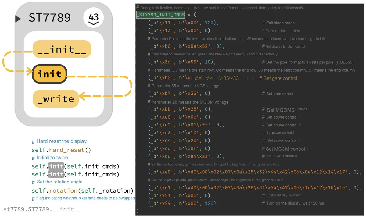
Here, after a hard reset of the display, the originally defined initialization command is sent (if no user-defined initialization command is available):
def init(self, commands: tuple) -> None:
    """
    Initialize the screen.

    Args:
        commands (tuple): Tuple of initialization commands. Each element should be a 3-tuple: (command_bytes, data_bytes, delay_ms).
                          - command_bytes (bytes): Command byte sequence (MicroPython built-in type: bytes)
                          - data_bytes (bytes): Data byte sequence sent immediately after the command (MicroPython built-in type: bytes)
                          - delay_ms (int): Number of milliseconds to wait after sending the command (MicroPython built-in type: int)
                      The overall type is tuple (MicroPython built-in type: tuple), for example:
                      ((b'\x01', b'', 150), (b'\x11', b'', 255), ...)

    Returns:
        None: This method returns no value. (MicroPython built-in type: None)

    Raises:
        TypeError: If commands is not an iterable sequence of 3-tuples, the caller may receive this exception (the implementation raises it during iteration/unpacking).
    """
    for command, data, delay in commands:
        self._write(command, data)
        time.sleep_ms(delay)

def _write(self, command: bytes = None, data: bytes = None) -> None:
    """
    Write data or a command to the screen.

    Args:
        command (bytes, optional): Command byte sequence to send; pass None if there is no command. Default None. (MicroPython built-in type: bytes or None)
        data (bytes, optional): Data byte sequence to send; pass None if there is no data. Default None. (MicroPython built-in type: bytes or None)

    Returns:
        None: This method returns no value. (MicroPython built-in type: None)

    Notes:
        - If a chip select pin (self.cs) exists, it is pulled low before sending to select the device; data/command selection is controlled by the dc pin.
        - This method assumes self.spi, self.dc, and self.cs have all been initialized as needed and that the corresponding methods (on/off/write) can be called safely.
    """
    if self.cs:
        # Set the CS pin low to select the device
        self.cs.off()
    if command is not None:
        # Set the DC pin low to send a command
        self.dc.off()
        # Send the command bytes to the device
        self.spi.write(command)
    if data is not None:
        # Set the DC pin high to send data
        self.dc.on()
        # Send the data bytes to the device
        self.spi.write(data)
        if self.cs:
            # Set the CS pin high to end the data transfer
            self.cs.on()
Then, the ST7789 class also defines other methods, including:
hard_reset: Hard reset the screen
soft_reset: Soft reset the screen
sleep_mode: Enable or disable the display sleep mode
inversion_mode: sets whether the screen display is inverted
rotation : Set display rotation
_set_window : Sets the window area, which is used to update the pixel data on the screen
vline, hline, pixel, blit_buffer, rect, fill_rect, fill, line: draw graphics of different shapes
vscrdef , vscsad : Set the vertical scrolling area and the starting address
_pack8, _pack16: Pack the character index, foreground color and background color into a byte array of pixel values
text, bitmap, pbitmap, write, write_width: used for drawing text and bitmaps
polygon : Draw a closed polygon
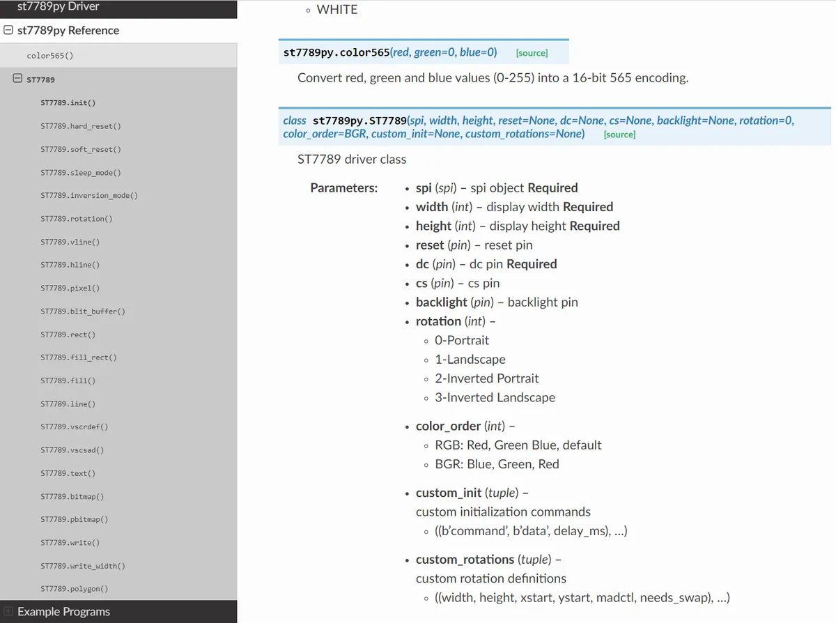
We can check the input parameters and the implemented display effects of these methods via the following link:
Next, we will introduce these methods one by one as follows:
hard_reset () is used to perform a hard reset on the ST7789 LCD screen. A hard reset is implemented by sending a sequence of level signals to the screen's RESET pin; this process forces the screen controller to restart, thereby restoring it to its initial state.
def hard_reset(self) -> None:
    """
    Hard reset the screen: generate the full reset sequence through the reset pin and wait for the chip to start up.

    Args:
        None

    Returns:
        None: This method returns no value. (MicroPython built-in type: None)

    Notes:
        - When a chip select pin (self.cs) exists, CS is pulled low before the reset to select the device, and pulled high after the reset completes to end the transfer.
        - Assumes self.reset and self.cs have been correctly initialized as machine.Pin instances providing on()/off() methods.
    """
    if self.cs:
        # Set the CS pin low to select the device
        self.cs.off()
    if self.reset:
        # Set the RESET pin high to begin resetting the screen
        self.reset.on()
    # Wait 10 milliseconds
    time.sleep_ms(10)
    if self.reset:
        # Set the RESET pin low to end resetting the screen
        self.reset.off()
    time.sleep_ms(10)
    if self.reset:
        # Set the RESET pin high to wake up the chip
        self.reset.on()
    # Wait 120 milliseconds to ensure the chip is fully initialized
    time.sleep_ms(120)
    if self.cs:
        # Set the CS pin high to end the data transfer
        self.cs.on()
soft_reset method is used to issue commands to perform a soft reset on the LCD screen. A soft reset is a non-destructive reset method for the ST7789 screen controller, which does not affect the content displayed on the screen nor cause data loss. In practical applications, a soft reset is typically used when configuration changes to the screen controller are required or to restore default settings.
def soft_reset(self) -> None:
    """
    Soft reset the screen: send the software reset command so that the display controller performs its reset procedure.

    Args:
        None

    Returns:
        None: This method returns no value. (MicroPython built-in type: None)

    Notes:
        - This method sends the _ST7789_SWRESET command to the device and waits a fixed delay to ensure it takes effect.
        - Assumes self._write is available and can correctly send commands to the display.
    """
    # Reset the LCD by sending the software reset command
    self._write(_ST7789_SWRESET)
    time.sleep_ms(150)
sleep_mode The method is used to enable or disable the display sleep mode, and can put the screen controller into a low-power state.
def sleep_mode(self, value: bool) -> None:
    """
    Enable or disable display sleep mode (Sleep In / Sleep Out).

    Args:
        value (bool): If True, enable sleep mode (send SLPIN); if False, exit sleep mode (send SLPOUT).
                      (MicroPython built-in type: bool)

    Returns:
        None: This method returns no value. (MicroPython built-in type: None)
    """
    if value:
        self._write(_ST7789_SLPIN)
    else:
        self._write(_ST7789_SLPOUT)
The inversion_mode method is used to set whether the screen display is inverted. Display inversion means that the color of the pixels on the screen is the opposite of their normal display. For example, a red pixel normally displays as red, while in inversion mode, it displays as green.
def inversion_mode(self, value: bool) -> None:
    """
    Set whether the screen display is inverted (Display Inversion On/Off).

    Args:
        value (bool): True turns on screen inversion (INVON), False turns off screen inversion (INVOFF).
                      (MicroPython built-in type: bool)

    Returns:
        None: This method returns no value. (MicroPython built-in type: None)
    """
    if value:
        self._write(_ST7789_INVON)
    else:
        self._write(_ST7789_INVOFF)
rotation is used to set the flip mode, including landscape display, portrait display, landscape flip, and portrait flip.
def rotation(self, rotation: int) -> None:
    """
    Set and apply the display rotation/flip mode (update the MADCTL register and adjust the logical width/height/offsets).

    Args:
        rotation (int): Rotation index (0-3), representing:
                       - 0: Portrait (default)
                       - 1: Landscape
                       - 2: Inverted Portrait
                       - 3: Inverted Landscape
                       (MicroPython built-in type: int)

    Returns:
        None: This method returns no value. (MicroPython built-in type: None)

    Raises:
        IndexError: If self.rotations is empty or has an incorrect structure, indexing may raise an exception (this is normally validated during initialization to avoid this case).
    """

    # Calculate the index after rotation
    rotation %= len(self.rotations)
    # Update the current rotation value
    self._rotation = rotation
    # Get the parameters after rotation
    (
        madctl,
        self.width,
        self.height,
        self.xstart,
        self.ystart,
        self.needs_swap,
    ) = self.rotations[rotation]

    # Set the MADCTL register according to the color order
    if self.color_order == BGR:
        madctl |= _ST7789_MADCTL_BGR
    else:
        madctl &= ~_ST7789_MADCTL_BGR
    # Write the MADCTL register
    self._write(_ST7789_MADCTL, bytes([madctl]))
_set_window method is used to set the window area and update the pixel data on the screen to the specified rectangular area. This function accepts four parameters: x0, y0, x1 and y1, which respectively represent the abscissa of the upper left corner, the ordinate of the upper left corner, the abscissa of the lower right corner and the ordinate of the lower right corner of the window area.
def _set_window(self, x0: int, y0: int, x1: int, y1: int) -> None:
    """
    Set the window area and update the pixel data on the screen within the specified rectangular area.

    Args:
        x0 (int): X coordinate of the top-left corner of the window area, in the range [0, self.width). (MicroPython built-in type: int)
        y0 (int): Y coordinate of the top-left corner of the window area, in the range [0, self.height). (MicroPython built-in type: int)
        x1 (int): X coordinate of the bottom-right corner of the window area, in the range [x0, self.width). (MicroPython built-in type: int)
        y1 (int): Y coordinate of the bottom-right corner of the window area, in the range [y0, self.height). (MicroPython built-in type: int)

    Returns:
        None: This method returns no value. (MicroPython built-in type: None)

    Notes:
        - If the provided coordinates are invalid (not satisfying x0 <= x1 <= self.width or y0 <= y1 <= self.height),
          this method performs no write operation and returns immediately.
        - Uses struct.pack to pack the coordinates in the format specified by _ENCODE_POS (usually big-endian, 2 bytes per item) and sends them to the CASET/RASET registers.
    """
    #  Check whether the input parameters are valid
    if x0 <= x1 <= self.width and y0 <= y1 <= self.height:
        # Write the column address range to the CASET register
        self._write(
            _ST7789_CASET,
            # The _ENCODE_POS variable is used as the pack format string, which specifies the byte order and size of each integer
            # _ENCODE_POS indicates big-endian byte order, with each integer taking two bytes
            # Pack the last two arguments according to the pack format string for transmission
            struct.pack(_ENCODE_POS, x0 + self.xstart, x1 + self.xstart),
        )
        # Write the row address range to the RASET register
        self._write(
            _ST7789_RASET,
            struct.pack(_ENCODE_POS, y0 + self.ystart, y1 + self.ystart),
        )
        # Start writing pixel data to display memory
        self._write(_ST7789_RAMWR)
The following methods are those we commonly use in drawing, including drawing horizontal line segments, vertical line segments, line segments, rectangles, filled rectangles, etc. , all of which are implemented by _write method to send corresponding data and commands to the ST7789 chip.
def vline(self, x: int, y: int, length: int, color: int) -> None:
    """
    Draw a vertical line at the specified position.

    Args:
        x (int): Starting X coordinate of the line (MicroPython built-in type: int).
        y (int): Starting Y coordinate of the line (MicroPython built-in type: int).
        length (int): Height of the line (in pixels) (MicroPython built-in type: int).
        color (int): Color value, 16-bit 565 encoding (MicroPython built-in type: int).

    Returns:
        None: This method returns no value. (MicroPython built-in type: None)
    """
    self.fill_rect(x, y, 1, length, color)

def hline(self, x: int, y: int, length: int, color: int) -> None:
    """
    Draw a horizontal line at the specified position.

    Args:
        x (int): Starting X coordinate of the line (MicroPython built-in type: int).
        y (int): Starting Y coordinate of the line (MicroPython built-in type: int).
        length (int): Width of the line (in pixels) (MicroPython built-in type: int).
        color (int): Color value, 16-bit 565 encoding (MicroPython built-in type: int).

    Returns:
        None: This method returns no value. (MicroPython built-in type: None)
    """
    self.fill_rect(x, y, length, 1, color)

def pixel(self, x: int, y: int, color: int) -> None:
    """
    Draw a single pixel at the specified position.

    Args:
        x (int): X coordinate of the pixel. (MicroPython built-in type: int)
        y (int): Y coordinate of the pixel. (MicroPython built-in type: int)
        color (int): Pixel color, 16-bit 565 encoding (MicroPython built-in type: int)

    Returns:
        None: This method returns no value. (MicroPython built-in type: None)

    Notes:
        - Calls _set_window to restrict the window to a single-pixel area, then sends the pixel in the packing format selected by self.needs_swap.
    """
    # Set the window area
    self._set_window(x, y, x, y)
    # Write the pixel data
    self._write(
        None,
        # Pack the color value color into a big-endian or little-endian byte string, depending on the value of self.needs_swap
        struct.pack(
            _ENCODE_PIXEL_SWAPPED if self.needs_swap else _ENCODE_PIXEL, color
        ),
    )

def blit_buffer(self, buffer: 'bytes | bytearray | memoryview', x: int, y: int, width: int, height: int) -> None:
    """
    Draw an image from a buffer at the specified position.

    Args:
        buffer (bytes | bytearray | memoryview): Image buffer to draw, organized in pixel order (MicroPython built-in type: bytes/bytearray/memoryview).
        x (int): Starting X coordinate of the image on the screen (MicroPython built-in type: int).
        y (int): Starting Y coordinate of the image on the screen (MicroPython built-in type: int).
        width (int): Width of the image (pixels) (MicroPython built-in type: int).
        height (int): Height of the image (pixels) (MicroPython built-in type: int).

    Returns:
        None: This method returns no value. (MicroPython built-in type: None)

    Notes:
        - Assumes the length of buffer matches width*height*(bytes_per_pixel).
        - This method does not strictly validate the buffer length; the caller must ensure data integrity.
    """
    # Set the window area
    self._set_window(x, y, x + width - 1, y + height - 1)
    # Draw an image from a buffer
    self._write(None, buffer)

def rect(self, x: int, y: int, w: int, h: int, color: int) -> None:
    """
    Draw a rectangle outline.

    Args:
        x (int): X coordinate of the top-left corner of the rectangle (MicroPython built-in type: int).
        y (int): Y coordinate of the top-left corner of the rectangle (MicroPython built-in type: int).
        w (int): Rectangle width (pixels) (MicroPython built-in type: int).
        h (int): Rectangle height (pixels) (MicroPython built-in type: int).
        color (int): Rectangle outline color, 16-bit 565 encoding (MicroPython built-in type: int).

    Returns:
        None: This method returns no value. (MicroPython built-in type: None)
    """
    self.hline(x, y, w, color)
    self.vline(x, y, h, color)
    self.vline(x + w - 1, y, h, color)
    self.hline(x, y + h - 1, w, color)

def fill_rect(self, x: int, y: int, width: int, height: int, color: int) -> None:
    """
    Draw a filled rectangle.

    Args:
        x (int): X coordinate of the top-left corner of the rectangle (MicroPython built-in type: int).
        y (int): Y coordinate of the top-left corner of the rectangle (MicroPython built-in type: int).
        width (int): Rectangle width (pixels) (MicroPython built-in type: int).
        height (int): Rectangle height (pixels) (MicroPython built-in type: int).
        color (int): Rectangle fill color, 16-bit 565 encoding (MicroPython built-in type: int).

    Returns:
        None: This method returns no value. (MicroPython built-in type: None)

    Notes:
        - Uses the constant _BUFFER_SIZE to send the pixels in chunks to save memory.
        - Selects the byte-order format for packing pixels, _ENCODE_PIXEL or _ENCODE_PIXEL_SWAPPED, according to self.needs_swap.
    """
    # Set the window area
    self._set_window(x, y, x + width - 1, y + height - 1)
    # Calculate the number of pixels in the rectangle and split it into chunks of size _BUFFER_SIZE
    # The divmod() function combines the division and remainder operations and returns a tuple containing the quotient and the remainder
    # chunks is the number of full chunks, rest is the number of remaining pixels that do not fill a chunk
    chunks, rest = divmod(width * height, _BUFFER_SIZE)
    # Pack the color value color into a pixel value
    # If self.needs_swap is true, pack using the _ENCODE_PIXEL_SWAPPED format
    # Otherwise, pack using the _ENCODE_PIXEL format
    pixel = struct.pack(
        _ENCODE_PIXEL_SWAPPED if self.needs_swap else _ENCODE_PIXEL, color
    )
    # Pull DC high to indicate data is being sent
    self.dc.on()
    # If there are full blocks, do the following
    if chunks:
        # Create a byte string containing multiple pixel values
        data = pixel * _BUFFER_SIZE
        # Write the current block's data to the device
        for _ in range(chunks):
            self._write(None, data)
    # If there are remaining pixels that do not fill a block, do the following
    if rest:
        # Write the remaining pixels' data to the device
        self._write(None, pixel * rest)

def fill(self, color: int) -> None:
    """
    Fill the entire screen with the specified color.

    Args:
        color (int): Fill color, 16-bit 565 encoding (MicroPython built-in type: int).

    Returns:
        None: This method returns no value. (MicroPython built-in type: None)
    """
    self.fill_rect(0, 0, self.width, self.height, color)

def line(self, x0: int, y0: int, x1: int, y1: int, color: int) -> None:
    """
    Draw a straight line (implemented with the Bresenham algorithm).

    Args:
        x0 (int): X coordinate of the start point (MicroPython built-in type: int).
        y0 (int): Y coordinate of the start point (MicroPython built-in type: int).
        x1 (int): X coordinate of the end point (MicroPython built-in type: int).
        y1 (int): Y coordinate of the end point (MicroPython built-in type: int).
        color (int): Line color, 16-bit 565 encoding (MicroPython built-in type: int).

    Returns:
        None: This method returns no value. (MicroPython built-in type: None)

    Notes:
        - If the line's slope is greater than 1, x/y are swapped to reduce the number of loop iterations (steep optimization).
    """
    # Check whether the line's slope is greater than 1; if so, swap x0 and y0 to optimize the computation
    steep = abs(y1 - y0) > abs(x1 - x0)
    if steep:
        x0, y0 = y0, x0
        x1, y1 = y1, x1
    # Ensure x0 is less than or equal to x1 so that points are processed in order
    if x0 > x1:
        x0, x1 = x1, x0
        y0, y1 = y1, y0
    # Calculate dx and dy, the increments along the x axis and y axis
    dx = x1 - x0
    dy = abs(y1 - y0)
    # Initialize the error value err, used to calculate the y coordinate at each step
    err = dx // 2
    # Determine the y-axis step from the slope, so that the y coordinate increases or decreases
    ystep = 1 if y0 < y1 else -1
    # While x0 is less than or equal to x1, loop to draw the line
    while x0 <= x1:
        # If the slope is greater than 1, draw points in the order y0, x0; otherwise draw points in the order x0, y0
        if steep:
            self.pixel(y0, x0, color)
        else:
            self.pixel(x0, y0, color)
        # Update the error value err
        err -= dy
        # If the error value is less than 0, the y coordinate needs to increase; update y0 and adjust the error value
        if err < 0:
            y0 += ystep
            err += dx
        # Increase the x coordinate to prepare for drawing the next point
        x0 += 1
vscrdef and vscsad are both functions used to configure the vertical scrolling feature of the ST7789 LCD screen:
vscrdef function is used to set the vertical scrolling area, and it accepts three parameters: tfa represents the top fixed area, vsa represents the vertical scrolling area, and bfa represents the bottom fixed area. These parameters define which rows should be regarded as fixed and which rows should be scrolled and displayed on the screen. The implementation of this function is to pack these values into a byte string and use the self._write () method to write them into the registers of the ST7789
vscsad function is used to set the vertical scroll start address, and it accepts one parameter: vssa, which represents the vertical scroll start address. This parameter defines the first line in the frame memory that is written to the display after the top fixed area. The implementation of this function is to pack this value into a byte string and use the self._write () method to write it to the register of the ST7789 LCD screen
These two functions are usually used to implement dynamic display effects on the screen, such as scrolling subtitles or images.
def vscrdef(self, tfa: int, vsa: int, bfa: int) -> None:
    """
    Set the vertical scroll display areas (Top Fixed Area / Vertical Scroll Area / Bottom Fixed Area).

    Example (for a 135x240 screen): tfa=40, vsa=240, bfa=40.

    Args:
        tfa (int): Height of the top fixed area, in pixels (MicroPython built-in type: int).
        vsa (int): Height of the vertical scroll area, in pixels (MicroPython built-in type: int).
        bfa (int): Height of the bottom fixed area, in pixels (MicroPython built-in type: int).

    Returns:
        None: This method returns no value. (MicroPython built-in type: None)
    """
    # Write the screen's vertical scroll start address, vertical scroll end address and buffer address to the registers of the ST7789 LCD
    self._write(_ST7789_VSCRDEF, struct.pack(">HHH", tfa, vsa, bfa))

def vscsad(self, vssa: int) -> None:
    """
    Set the vertical scroll start address (Vertical Scroll Start Address), which defines which row of frame memory is displayed first.

    Args:
        vssa (int): Vertical scroll start address (MicroPython built-in type: int).

    Returns:
        None: This method returns no value. (MicroPython built-in type: None)

    Example:
        for line in range(40, 280, 1):
            tft.vscsad(line)
            utime.sleep(0.01)
    """
    # Write the vertical scroll start address to the registers of the ST7789 LCD
    self._write(_ST7789_VSCSAD, struct.pack(">H", vssa))
Then, regarding the methods related to character display, a byte array packing method is first defined. The _pack8 and _pack16 methods are used to pack the character index (i. e., the font data), foreground color, and background color into a byte array of pixel values. Both of them are static methods, which means they can be called without creating an instance of the class:
_pack8 function is used to pack character indices, foreground colors and background colors into a byte array of 8-bit pixel values. It accepts four parameters: glyphs is a module containing glyph data for all characters, idx is the index of the character to be processed, fg_color is the foreground color, and bg_color is the background color. The implementation process of the function is as follows:
Create a byte array buffer with a size of 128 bytes.
Convert the buffer into a pointer bitmap pointing to 16-bit integers.
Convert glyphs into a pointer glyph that points to an 8-bit integer.
Iterate over 64 consecutive 8-bit pixels, fetch the byte data of the current character from the glyph, and set the pixel value at the corresponding position in the bitmap according to each bit of the byte.
Returns the packed byte array of pixel values.
_pack16 function is used to pack the character index, foreground color and background color into a byte array of 16-bit pixel values. It accepts four parameters: glyphs is a module containing the glyph data of all characters, idx is the character index to be processed, fg_color is the foreground color, and bg_color is the background color. The implementation process of the function is as follows:
Create a byte array buffer with a size of 256 bytes.
Convert the buffer into a bitmap that is a pointer to 16-bit integers.
Convert glyphs to a glyph pointer that points to an 8-bit integer.
Iterate through 128 consecutive 16-bit pixels, retrieve the glyph data of the current character from the glyph, and set the pixel value at the corresponding position in the bitmap according to each bit of the glyph.
Returns the packed byte array of pixel values.
# Use the Viper code emitter
@micropython.viper
# Static method decorator; static methods are usually used to implement class-related functionality but do not need to access instance variables or methods
@staticmethod
def _pack8(glyphs, idx: int, fg_color: int, bg_color: int):
    """
    Pack the given character index, foreground color and background color into a byte array of 8-bit pixel values (for an 8x8 glyph or each half of an 8x16 glyph).
    @micropython.viper does not support advanced type annotations in the function signature such as bytearray, union types (bytes | bytearray | memoryview) or return type annotations (-> bytearray)

    Args:
        glyphs (bytes | bytearray | memoryview): Glyph table containing the glyph data of the characters (MicroPython built-in types: bytes/bytearray/memoryview).
        idx (int): Starting index offset in the glyph table of the character to process (MicroPython built-in type: int).
        fg_color (int): Foreground color (used where the pixel is 1) (MicroPython built-in type: int).
        bg_color (int): Background color (used where the pixel is 0) (MicroPython built-in type: int).

    Returns:
        bytearray: Returns a byte array containing the packed pixel values (128 bytes long), which can be used directly with blit (MicroPython built-in type: bytearray).

    Notes:
        - This function is optimized with viper and assumes the ptr8/ptr16 type-cast functions are available for speed.
    """
    # Create a byte array buffer of 128 bytes
    buffer  = bytearray(128)
    # Ignore PyCharm's warnings about ptr16 and ptr8
    # Cast buffer to a pointer to 16-bit integers, bitmap
    bitmap  = ptr16(buffer)
    # Cast glyphs to a pointer to 8-bit integers, glyph
    glyph   = ptr8(glyphs)

    # # Iterate over 64 consecutive 8-bit pixels
    for i in range(0, 64, 8):
        # # Get the byte data of the current character from glyph
        byte = glyph[idx]
        # Set the pixel values at the corresponding positions in bitmap according to each bit of the byte
        # If the current bit is 1, the pixel value is the foreground color; otherwise it is the background color
        bitmap[i] = fg_color if byte & _BIT7 else bg_color
        bitmap[i + 1] = fg_color if byte & _BIT6 else bg_color
        bitmap[i + 2] = fg_color if byte & _BIT5 else bg_color
        bitmap[i + 3] = fg_color if byte & _BIT4 else bg_color
        bitmap[i + 4] = fg_color if byte & _BIT3 else bg_color
        bitmap[i + 5] = fg_color if byte & _BIT2 else bg_color
        bitmap[i + 6] = fg_color if byte & _BIT1 else bg_color
        bitmap[i + 7] = fg_color if byte & _BIT0 else bg_color
        # Process the next character
        idx += 1

    # Return the byte array of packed pixel values
    return buffer

@micropython.viper
@staticmethod
def _pack16(glyphs, idx: int, fg_color: int, bg_color: int):
    """
    Pack the given character index, foreground color and background color into a byte array of 16-bit pixel values (for 16-wide characters, packing 128 16-bit pixels at a time -> 256 bytes).
    @micropython.viper does not support advanced type annotations in the function signature such as bytearray, union types (bytes | bytearray | memoryview) or return type annotations (-> bytearray)

    Args:
        glyphs (bytes | bytearray | memoryview): Glyph table (MicroPython built-in types: bytes/bytearray/memoryview).
        idx (int): Starting byte index in the glyph table (MicroPython built-in type: int).
        fg_color (int): Foreground color (MicroPython built-in type: int).
        bg_color (int): Background color (MicroPython built-in type: int).

    Returns:
        bytearray: Returns a byte array containing the packed pixel values (256 bytes long), which can be used directly with blit (MicroPython built-in type: bytearray).
    """

    # Create a byte array buffer of 256 bytes
    buffer = bytearray(256)
    # Ignore PyCharm's warnings about ptr16 and ptr8
    bitmap = ptr16(buffer)
    glyph = ptr8(glyphs)

    # Iterate over 128 consecutive 16-bit pixels
    for i in range(0, 128, 16):
        # Get the glyph data of the current character
        byte = glyph[idx]

        # Set the color of the pixels according to each bit of the glyph
        bitmap[i] = fg_color if byte & _BIT7 else bg_color
        bitmap[i + 1] = fg_color if byte & _BIT6 else bg_color
        bitmap[i + 2] = fg_color if byte & _BIT5 else bg_color
        bitmap[i + 3] = fg_color if byte & _BIT4 else bg_color
        bitmap[i + 4] = fg_color if byte & _BIT3 else bg_color
        bitmap[i + 5] = fg_color if byte & _BIT2 else bg_color
        bitmap[i + 6] = fg_color if byte & _BIT1 else bg_color
        bitmap[i + 7] = fg_color if byte & _BIT0 else bg_color
        # Update the character index
        idx += 1

        # Get the glyph data of the next character
        byte = glyph[idx]
        bitmap[i + 8] = fg_color if byte & _BIT7 else bg_color
        bitmap[i + 9] = fg_color if byte & _BIT6 else bg_color
        bitmap[i + 10] = fg_color if byte & _BIT5 else bg_color
        bitmap[i + 11] = fg_color if byte & _BIT4 else bg_color
        bitmap[i + 12] = fg_color if byte & _BIT3 else bg_color
        bitmap[i + 13] = fg_color if byte & _BIT2 else bg_color
        bitmap[i + 14] = fg_color if byte & _BIT1 else bg_color
        bitmap[i + 15] = fg_color if byte & _BIT0 else bg_color
        # Update the character index
        idx += 1

    return buffer
Here, we use @micropython.viper as a decorator, and the Viper code emitter will generate ARM-Thumb machine code for each bytecode, and further optimize certain operations such as integer arithmetic.
When MicroPython compiles code, it processes each function individually (classes are functions, as are lambdas and list comprehensions). Functions emerge from the parsing phase and then enter the compiler, which passes the Python function three times.
In the first phase, the compiler collects information about variables and their scopes (local or global), and determines the emitter type by looking for special types of function decorators.
In the second phase, it calculates the stack usage and code offsets
In the third stage, the code is transmitted by the required transmitter
Both the ptr16 and ptr8 pointer types are used, and pointers provide direct access to the data stored in memory. Subscript notation is used to access items, but slicing is not supported: pointers can only return a single item. The purpose of using pointers is to provide fast random access to data stored in contiguous memory locations, such as data stored in objects that support the buffer protocol and memory-mapped peripheral registers in microcontrollers. It should be noted that programming with pointers is dangerous: no bounds checking is performed, and the compiler takes no measures to prevent buffer overflow errors.
Then comes the code related to character rendering. Here, we use the text method to draw characters, and the text method will select different rendering methods according to the width and height of the font: the _text8 method and the _text16 method. The implementation process of the _text8 function is as follows:
Iterate through each character in the text
Convert characters to ASCII codes
Check whether the character is within the range supported by the font and whether the current position does not exceed the screen range
Select the drawing method according to the font height: if the font height is 8, draw 8x8-pixel characters; if the font height is 16, draw 16x16-pixel characters
Iterate through each line, calculate the index of the current character in the font, and pack the character data into an 8-bit binary format
Draw the packed character data on the screen
Update the starting column of the next character
The implementation process of the _text16 function is similar to that of _text8.
def _text8(self, font, text: str, x0: int, y0: int, fg_color: int = WHITE, bg_color: int = BLACK) -> None:
    """
    Used to draw characters with a width of 8 (height 8 or 16).

    Args:
        font (module | object): Font module/object, which must contain the FIRST, LAST, WIDTH, HEIGHT, FONT constants/attributes (MicroPython built-in types: module/object).
        text (str): The text string to draw. (MicroPython built-in type: str)
        x0 (int): Column at which to start drawing (MicroPython built-in type: int).
        y0 (int): Row at which to start drawing (MicroPython built-in type: int).
        fg_color (int, optional): Foreground color (default WHITE). (MicroPython built-in type: int)
        bg_color (int, optional): Background color (default BLACK). (MicroPython built-in type: int)

    Returns:
        None: This method returns no value. (MicroPython built-in type: None)
    """

    # Iterate over each character in the text
    for char in text:
        # Convert the character to its ASCII code
        ch = ord(char)
        # Check whether the character is within the range supported by the font and the current position is not beyond the screen
        if (
            font.FIRST <= ch < font.LAST
            and x0 + font.WIDTH <= self.width
            and y0 + font.HEIGHT <= self.height
        ):
            # Choose the drawing method according to the font height
            if font.HEIGHT == 8:
                # Draw an 8x8-pixel character
                passes = 1
                size = 8
                each = 0
            else:
                # Draw a 16x16-pixel character
                passes = 2
                size = 16
                each = 8
            # Iterate over each row
            for line in range(passes):
                # Calculate the index of the current character in the font
                idx = (ch - font.FIRST) * size + (each * line)
                # Pack the character data into 8-bit binary format
                buffer = self._pack8(font.FONT, idx, fg_color, bg_color)
                # Draw the packed character data on the screen
                self.blit_buffer(buffer, x0, y0 + 8 * line, 8, 8)
            # Update the starting column of the next character
            x0 += 8

def _text16(self, font, text: str, x0: int, y0: int, fg_color: int = WHITE, bg_color: int = BLACK) -> None:
    """
    Used to draw characters with a width of 16 (height 16 or 32).

    Args:
        font (module | object): Font module/object, which must contain the FIRST, LAST, WIDTH, HEIGHT, FONT constants/attributes (MicroPython built-in types: module/object).
        text (str): The text string to draw. (MicroPython built-in type: str)
        x0 (int): Column at which to start drawing (MicroPython built-in type: int).
        y0 (int): Row at which to start drawing (MicroPython built-in type: int).
        fg_color (int, optional): Foreground color (default WHITE). (MicroPython built-in type: int)
        bg_color (int, optional): Background color (default BLACK). (MicroPython built-in type: int)

    Returns:
        None: This method returns no value. (MicroPython built-in type: None)
    """
    # Iterate over each character in the text
    for char in text:
        # Convert the character to its ASCII code
        ch = ord(char)
        # Check whether the character is within the range supported by the font and the current position is not beyond the screen
        if (
            font.FIRST <= ch < font.LAST
            and x0 + font.WIDTH <= self.width
            and y0 + font.HEIGHT <= self.height
        ):
            # Decide how many rows to draw according to the font height
            each = 16
            if font.HEIGHT == 16:
                passes = 2
                size = 32
            else:
                passes = 4
                size = 64

            # Iterate over each row
            for line in range(passes):
                # Calculate the index of the current character in the font
                idx = (ch - font.FIRST) * size + (each * line)
                # Pack the character data into a buffer of 16-bit bytes
                buffer = self._pack16(font.FONT, idx, fg_color, bg_color)
                # Draw the buffer on the screen
                self.blit_buffer(buffer, x0, y0 + 8 * line, 16, 8)
        # Move to the position of the next character
        x0 += 16

def text(self, font, text: str, x0: int, y0: int, color: int = WHITE, background: int = BLACK) -> None:
    """
    Draw text at the specified position.

    Args:
        font (module | object): Font module/object to use, which must contain attributes such as WIDTH and HEIGHT. (MicroPython built-in types: module/object)
        text (str): The text string to write. (MicroPython built-in type: str)
        x0 (int): Column at which to start drawing (MicroPython built-in type: int)
        y0 (int): Row at which to start drawing (MicroPython built-in type: int)
        color (int, optional): Foreground color (default WHITE), 16-bit 565 encoding. (MicroPython built-in type: int)
        background (int, optional): Background color (default BLACK), 16-bit 565 encoding. (MicroPython built-in type: int)

    Returns:
        None: This method returns no value. (MicroPython built-in type: None)

    Notes:
        - Adjust the byte order of the foreground and background colors according to self.needs_swap, then choose _text8 or _text16 according to the font width.
    """
    # Adjust the byte order of the foreground and background colors depending on whether byte swapping is currently needed
    fg_color = color if self.needs_swap else ((color << 8) & 0xFF00) | (color >> 8)
    bg_color = (
        background
        if self.needs_swap
        else ((background << 8) & 0xFF00) | (background >> 8)
    )
    # If the font width is 8 bits, call the _text8 method to draw the text
    if font.WIDTH == 8:
        self._text8(font, text, x0, y0, fg_color, bg_color)
    # Otherwise, call the _text16 method to draw the text
    else:
        self._text16(font, text, x0, y0, fg_color, bg_color)
bitmap methods and pbitmap methods are both used for drawing bitmaps on the ST7789 LCD screen. Their main difference lies in the drawing method: bitmap function draws the entire bitmap at one time, while the pbitmap function draws only one line at a time.
The implementation process of the bitmap function is as follows:
Obtain the width, height, size, bit depth, starting bit, color palette of the bitmap and whether byte order swapping is required
Create a buffer for storing the byte value of each pixel
Traverse each row of the bitmap, and for each row, traverse every pixel in the current row, extract the pixel color from the bitmap, and swap the high and low bits of the color value according to the byte order of the current device
Write the processed pixel data into the buffer
Set the window area and write the data in the buffer to the screen
The implementation process of the pbitmap method is similar to that of bitmap, except that it only draws one row at a time. Specifically, it iterates over each row of the bitmap; for each row, it iterates over every pixel in the current row, extracts the pixel color from the bitmap, and swaps the high and low bits of the color value according to the byte order of the current device. It then writes the processed pixel data to the buffer. Finally, it sets the window area and writes the data in the buffer to the screen.
def bitmap(self, bitmap, x: int, y: int, index: int = 0) -> None:
    """
    Draw a bitmap at the specified position (packs the whole bitmap into memory at once and writes it out).

    Args:
        bitmap (module | object): Bitmap module/object, which must contain attributes such as WIDTH, HEIGHT, BPP, PALETTE and BITMAP. (MicroPython built-in types: module/object)
        x (int): X coordinate at which drawing starts. (MicroPython built-in type: int)
        y (int): Y coordinate at which drawing starts. (MicroPython built-in type: int)
        index (int, optional): Bitmap palette index offset, default 0. (MicroPython built-in type: int)

    Returns:
        None: This method returns no value. (MicroPython built-in type: None)

    Notes:
        - Each pixel takes two bytes (16-bit), and the generated buffer size is width*height*2 bytes.
        - The caller must ensure the drawing area does not exceed the display range, or accept that it will be truncated.
    """
    # Bitmap width
    width = bitmap.WIDTH
    # Bitmap height
    height = bitmap.HEIGHT
    # X coordinate where drawing ends
    to_col = x + width - 1
    # Y coordinate where drawing ends
    to_row = y + height - 1
    # If the drawing area exceeds the screen range, return directly
    if self.width <= to_col or self.height <= to_row:
        return

    # Bitmap size
    bitmap_size = height * width
    # Buffer length, each pixel takes two bytes
    buffer_len = bitmap_size * 2
    # Number of bits per pixel of the bitmap
    bpp = bitmap.BPP
    # If index > 0, start from the corresponding palette index; otherwise start from the first palette index
    bs_bit = bpp * bitmap_size * index  # if index > 0 else 0
    # Bitmap palette
    palette = bitmap.PALETTE
    # Flag indicating whether byte order swapping is needed
    needs_swap = self.needs_swap
    # Create buffer
    buffer = bytearray(buffer_len)

    for i in range(0, buffer_len, 2):
        color_index = 0
        for _ in range(bpp):
            color_index = (color_index << 1) | (
                (bitmap.BITMAP[bs_bit >> 3] >> (7 - (bs_bit & 7))) & 1
            )
            bs_bit += 1

        # Get the color value corresponding to the current pixel
        color = palette[color_index]
        if needs_swap:
            # Split the color value into two bytes, low byte first
            buffer[i] = color & 0xFF
            # High byte last
            buffer[i + 1] = color >> 8
        else:
            # Split the color value into two bytes, high byte first
            buffer[i] = color >> 8
            # Low byte last
            buffer[i + 1] = color & 0xFF

    # Set the window area
    self._set_window(x, y, to_col, to_row)
    # Write the data in the buffer to the screen
    self._write(None, buffer)

def pbitmap(self, bitmap, x: int, y: int, index: int = 0) -> None:
    """
    Draw a bitmap at the specified position row by row (saves memory, writes one row at a time).

    Args:
        bitmap (module | object): Bitmap module/object, which must contain attributes such as WIDTH, HEIGHT, BPP, PALETTE and BITMAP. (MicroPython built-in types: module/object)
        x (int): X coordinate at which drawing starts. (MicroPython built-in type: int)
        y (int): Y coordinate at which drawing starts. (MicroPython built-in type: int)
        index (int, optional): Bitmap palette index offset, default 0. (MicroPython built-in type: int)

    Returns:
        None: This method returns no value. (MicroPython built-in type: None)
    """
    # Get the bitmap's width, height, size, bit depth, start bit, palette, and whether byte order needs to be swapped
    width = bitmap.WIDTH
    height = bitmap.HEIGHT
    bitmap_size = height * width
    bpp = bitmap.BPP
    bs_bit = bpp * bitmap_size * index  # if index > 0 else 0
    palette = bitmap.PALETTE
    needs_swap = self.needs_swap
    # Create a byte array twice the bitmap width to store the byte values of each pixel
    buffer = bytearray(bitmap.WIDTH * 2)

    # Iterate over each row of the bitmap
    for row in range(height):
        # Iterate over each pixel in the current row
        for col in range(width):
            color_index = 0
            # Extract pixel colors from MSB to LSB
            for _ in range(bpp):
                color_index <<= 1
                color_index |= (
                    bitmap.BITMAP[bs_bit // 8] & 1 << (7 - (bs_bit % 8))
                ) > 0
                bs_bit += 1
            color = palette[color_index]
            # Swap the high and low bytes of the color value according to the current device's byte order
            if needs_swap:
                buffer[col * 2] = color & 0xFF
                buffer[col * 2 + 1] = color >> 8 & 0xFF
            else:
                buffer[col * 2] = color >> 8 & 0xFF
                buffer[col * 2 + 1] = color & 0xFF
        # Calculate the coordinates after the current row is drawn
        to_col = x + width - 1
        to_row = y + row
        # If the current coordinates are within the current device's display range, draw the row
        if self.width > to_col and self.height > to_row:
            self._set_window(x, y + row, to_col, to_row)
            self._write(None, buffer)
write method is used to write a string in TrueType font starting from the specified column and row on the ST7789 LCD screen. TrueType font is a kind of vector font, which uses mathematical formulas to describe the shape of characters, so it can be scaled infinitely without distortion. Compared with bitmap fonts, TrueType fonts have higher clarity and smaller file sizes.
The implementation process of the write method is as follows:
Create a byte array buffer with a length of buffer_len, which is used to store the pixel data of characters.
Calculate the high-order and low-order bytes of the foreground color and the background color.
Iterate through each character in the string.
Attempts to retrieve the index of the current character in the font mapping table.
Calculate the offset of the character based on the index and obtain the bitmap data of the character.
Get the width of the character.
Calculate the length of the data that needs to be written to the buffer.
Iterate through each pixel of the character, and set the pixel values in the buffer according to the bitmap data.
Calculate the end column and row position of the character on the display screen.
Check whether the current character is within the drawable area of the display screen.
If the character is within the drawable area, set the window region and write the buffer data.
Update the line position of the current character.
If a character that cannot be found in the font mapping table is encountered, the character will be ignored.
def write(self, font, string: str, x: int, y: int, fg: int = WHITE, bg: int = BLACK) -> None:
    """
    Write a string on the display starting at the specified column and row, using a converted TrueType-style font.

    Args:
        font (module | object): Converted font object; must include attributes such as HEIGHT, MAX_WIDTH, MAP, OFFSET_WIDTH, OFFSETS, WIDTHS, BITMAPS. (MicroPython built-in type: module/object)
        string (str): The text string to write. (MicroPython built-in type: str)
        x (int): Column to start drawing at (MicroPython built-in type: int)
        y (int): Row to start drawing at (MicroPython built-in type: int)
        fg (int, optional): Foreground color, default is WHITE. (MicroPython built-in type: int)
        bg (int, optional): Background color, default is BLACK. (MicroPython built-in type: int)

    Returns:
        None: This method returns no value. (MicroPython built-in type: None)
    """
    buffer_len = font.HEIGHT * font.MAX_WIDTH * 2
    # Create a byte array `buffer` of length `buffer_len` to store the character's pixel data
    buffer = bytearray(buffer_len)
    # Calculate the high and low bytes of the foreground and background colors
    fg_hi = fg >> 8
    fg_lo = fg & 0xFF

    bg_hi = bg >> 8
    bg_lo = bg & 0xFF

    # Iterate over each character in the string
    for character in string:
        try:
            # Try to get the index of the current character in the font map
            char_index = font.MAP.index(character)
            # Calculate the character's offset from the index and get the character's bitmap data
            offset = char_index * font.OFFSET_WIDTH
            bs_bit = font.OFFSETS[offset]
            if font.OFFSET_WIDTH > 1:
                bs_bit = (bs_bit << 8) + font.OFFSETS[offset + 1]

            if font.OFFSET_WIDTH > 2:
                bs_bit = (bs_bit << 8) + font.OFFSETS[offset + 2]
            # Get the character's width
            char_width = font.WIDTHS[char_index]
            # Calculate the length of data to write to the buffer
            buffer_needed = char_width * font.HEIGHT * 2

            # Iterate over each pixel of the character and set the pixel values in the buffer according to the bitmap data
            for i in range(0, buffer_needed, 2):
                if font.BITMAPS[bs_bit // 8] & 1 << (7 - (bs_bit % 8)) > 0:
                    buffer[i] = fg_hi
                    buffer[i + 1] = fg_lo
                else:
                    buffer[i] = bg_hi
                    buffer[i + 1] = bg_lo

                bs_bit += 1
            # Calculate the end column and row position of the character on the display
            to_col = x + char_width - 1
            to_row = y + font.HEIGHT - 1
            # Check whether the current character is within the drawable area of the display
            if self.width > to_col and self.height > to_row:
                # Set the window area and write the buffer data
                self._set_window(x, y, to_col, to_row)
                self._write(None, buffer[:buffer_needed])
            # Update the row position of the current character
            x += char_width

        except ValueError:
            # If a character is not found in the font map, ignore it
            pass
write_width The method is used to calculate the width occupied on the display screen by a string rendered in a specific font. Its main function is to compute the width required for the text before drawing it, so as to reserve sufficient space on the screen. This is extremely useful for scenarios such as dynamic text display or text alignment.
def write_width(self, font, string: str) -> int:
    """
    Calculate the total width (in pixels) occupied when drawing a string with the specified font.

    Args:
        font (module | object): Font module/object; must include MAP and WIDTHS. (MicroPython built-in type: module/object)
        string (str): The string to measure. (MicroPython built-in type: str)

    Returns:
        int: Pixel width occupied by the string. (MicroPython built-in type: int)
    """
    # Initialize width to 0
    width = 0

    # Iterate over each character in the string
    for character in string:
        try:
            # Find the corresponding character index in the font's MAP attribute
            char_index = font.MAP.index(character)
            # If successful, add the character width to the total width
            width += font.WIDTHS[char_index]
        # If the index does not exist (i.e., the character is not in the font), skip the character
        except ValueError:
            pass

    # Return the calculated width
    return width
polygon method is used to draw closed polygons on the ST7789 LCD screen, and it accepts seven parameters: points is a list containing the vertices of the polygon, x and y are the coordinates of the polygon's center point respectively, color is the fill color of the polygon, angle is the rotation angle of the polygon (defaulting to 0 degrees), and center_x and center_y are the X and Y coordinates of the polygon's rotation center respectively (defaulting to 0).
The workflow it implements is as follows:
Check whether the number of points of the polygon is less than 3, and throw a ValueError exception if it is
If there is a rotation angle, calculate the coordinates of the rotated point; otherwise, directly add the offset to the point coordinates.
Iterate through the list of rotated points, and draw the line segments between adjacent points in sequence
@micropython.native
def polygon(self, points, x: int, y: int, color: int, angle: float = 0.0, center_x: int = 0,
            center_y: int = 0) -> None:
    """
    Draw a closed polygon.

    Args:
        points (list): List of points to draw, each point is an (x, y) tuple. (MicroPython built-in type: list/tuple)
        x (int): Overall X offset of the polygon. (MicroPython built-in type: int)
        y (int): Overall Y offset of the polygon. (MicroPython built-in type: int)
        color (int): Drawing color, 16-bit 565 encoding. (MicroPython built-in type: int)
        angle (float, optional): Rotation angle (in radians), default 0. If 0, no rotation is applied. (MicroPython built-in type: float)
        center_x (int, optional): X coordinate offset of the rotation center, default 0. (MicroPython built-in type: int)
        center_y (int, optional): Y coordinate offset of the rotation center, default 0. (MicroPython built-in type: int)

    Returns:
        None: This method returns no value. (MicroPython built-in type: None)

    Raises:
        ValueError: Raised when the number of points in points is less than 3.
    """
    # Check whether the number of polygon points is less than 3; if so, raise a ValueError exception
    if len(points) < 3:
        raise ValueError("Polygon must have at least 3 points.")
    # If there is a rotation angle, calculate the rotated point coordinates
    if angle:
        cos_a = cos(angle)
        sin_a = sin(angle)
        rotated = [
            (
                x
                + center_x
                + int(
                    (point[0] - center_x) * cos_a - (point[1] - center_y) * sin_a
                ),
                y
                + center_y
                + int(
                    (point[0] - center_x) * sin_a + (point[1] - center_y) * cos_a
                ),
            )
            for point in points
        ]
    else:
        # If there is no rotation angle, add the offset directly to the point coordinates
        rotated = [(x + int((point[0])), y + int((point[1]))) for point in points]

    # Iterate over the list of rotated points and draw line segments between each pair of adjacent points
    for i in range(1, len(rotated)):
        self.line(
            rotated[i - 1][0],
            rotated[i - 1][1],
            rotated[i][0],
            rotated[i][1],
            color,
        )
This section of code provides multiple methods for the ST7789 class, including initialization, hardware and software reset, data and command writing, as well as text and graphics rendering. It should be noted that when using this code to control the LCD screen to display text, a font library also needs to be imported. Simply put, the font library stores the dot matrix set of pixel points occupied by the corresponding image file when each character is displayed on the LCD screen.
Here, we have created three font files:
vga1_16x32.py: A font library with a width of 8 pixels and a height of 32 pixels, covering the character range 0x00 - 0x7F
vga1_16x16.py: A font library with a width of 16 pixels and a height of 16 pixels, featuring a character range of 0x00 to 0x7F
vga1_8x8.py: A font library with a width of 8 pixels and a height of 8 pixels, covering the character range 0x00 - 0x7F
The code of the vga1_8x8.py font library file is as follows:
# Python env   : MicroPython v1.23.0
# -*- coding: utf-8 -*-
# @Time    : 2024/7/6 11:43 PM
# @Author  : Li Qingshui
# @File    : vga1_8x8.py
# @Description : vga_8x8 font library
# Reference: russhughes st7789py_mpy: https://github.com/russhughes/st7789py_mpy/blob/master/lib/st7789py.py

# Width is 8 pixels
WIDTH = 8
# Height is 8 pixels
HEIGHT = 8
# The ASCII code of the first ASCII character is 0x20
FIRST = 0x20
# The ASCII code of the last ASCII character is 0x7f
LAST = 0x7f

_FONT =\
b'\x00\x00\x00\x00\x00\x00\x00\x00'\
b'\x18\x3c\x3c\x18\x18\x00\x18\x00'\
b'\x66\x66\x24\x00\x00\x00\x00\x00'\
b'\x6c\x6c\xfe\x6c\xfe\x6c\x6c\x00'\
b'\x18\x3e\x60\x3c\x06\x7c\x18\x00'\
b'\x00\xc6\xcc\x18\x30\x66\xc6\x00'\
b'\x38\x6c\x38\x76\xdc\xcc\x76\x00'\
b'\x18\x18\x30\x00\x00\x00\x00\x00'\
b'\x0c\x18\x30\x30\x30\x18\x0c\x00'\
b'\x30\x18\x0c\x0c\x0c\x18\x30\x00'\
b'\x00\x66\x3c\xff\x3c\x66\x00\x00'\
b'\x00\x18\x18\x7e\x18\x18\x00\x00'\
b'\x00\x00\x00\x00\x00\x18\x18\x30'\
b'\x00\x00\x00\x7e\x00\x00\x00\x00'\
b'\x00\x00\x00\x00\x00\x18\x18\x00'\
b'\x06\x0c\x18\x30\x60\xc0\x80\x00'\
b'\x38\x6c\xc6\xd6\xc6\x6c\x38\x00'\
b'\x18\x38\x18\x18\x18\x18\x7e\x00'\
b'\x7c\xc6\x06\x1c\x30\x66\xfe\x00'\
b'\x7c\xc6\x06\x3c\x06\xc6\x7c\x00'\
b'\x1c\x3c\x6c\xcc\xfe\x0c\x1e\x00'\
b'\xfe\xc0\xc0\xfc\x06\xc6\x7c\x00'\
b'\x38\x60\xc0\xfc\xc6\xc6\x7c\x00'\
b'\xfe\xc6\x0c\x18\x30\x30\x30\x00'\
b'\x7c\xc6\xc6\x7c\xc6\xc6\x7c\x00'\
b'\x7c\xc6\xc6\x7e\x06\x0c\x78\x00'\
b'\x00\x18\x18\x00\x00\x18\x18\x00'\
b'\x00\x18\x18\x00\x00\x18\x18\x30'\
b'\x06\x0c\x18\x30\x18\x0c\x06\x00'\
b'\x00\x00\x7e\x00\x00\x7e\x00\x00'\
b'\x60\x30\x18\x0c\x18\x30\x60\x00'\
b'\x7c\xc6\x0c\x18\x18\x00\x18\x00'\
b'\x7c\xc6\xde\xde\xde\xc0\x78\x00'\
b'\x38\x6c\xc6\xfe\xc6\xc6\xc6\x00'\
b'\xfc\x66\x66\x7c\x66\x66\xfc\x00'\
b'\x3c\x66\xc0\xc0\xc0\x66\x3c\x00'\
b'\xf8\x6c\x66\x66\x66\x6c\xf8\x00'\
b'\xfe\x62\x68\x78\x68\x62\xfe\x00'\
b'\xfe\x62\x68\x78\x68\x60\xf0\x00'\
b'\x3c\x66\xc0\xc0\xce\x66\x3a\x00'\
b'\xc6\xc6\xc6\xfe\xc6\xc6\xc6\x00'\
b'\x3c\x18\x18\x18\x18\x18\x3c\x00'\
b'\x1e\x0c\x0c\x0c\xcc\xcc\x78\x00'\
b'\xe6\x66\x6c\x78\x6c\x66\xe6\x00'\
b'\xf0\x60\x60\x60\x62\x66\xfe\x00'\
b'\xc6\xee\xfe\xfe\xd6\xc6\xc6\x00'\
b'\xc6\xe6\xf6\xde\xce\xc6\xc6\x00'\
b'\x7c\xc6\xc6\xc6\xc6\xc6\x7c\x00'\
b'\xfc\x66\x66\x7c\x60\x60\xf0\x00'\
b'\x7c\xc6\xc6\xc6\xc6\xce\x7c\x0e'\
b'\xfc\x66\x66\x7c\x6c\x66\xe6\x00'\
b'\x3c\x66\x30\x18\x0c\x66\x3c\x00'\
b'\x7e\x7e\x5a\x18\x18\x18\x3c\x00'\
b'\xc6\xc6\xc6\xc6\xc6\xc6\x7c\x00'\
b'\xc6\xc6\xc6\xc6\xc6\x6c\x38\x00'\
b'\xc6\xc6\xc6\xd6\xd6\xfe\x6c\x00'\
b'\xc6\xc6\x6c\x38\x6c\xc6\xc6\x00'\
b'\x66\x66\x66\x3c\x18\x18\x3c\x00'\
b'\xfe\xc6\x8c\x18\x32\x66\xfe\x00'\
b'\x3c\x30\x30\x30\x30\x30\x3c\x00'\
b'\xc0\x60\x30\x18\x0c\x06\x02\x00'\
b'\x3c\x0c\x0c\x0c\x0c\x0c\x3c\x00'\
b'\x10\x38\x6c\xc6\x00\x00\x00\x00'\
b'\x00\x00\x00\x00\x00\x00\x00\xff'\
b'\x30\x18\x0c\x00\x00\x00\x00\x00'\
b'\x00\x00\x78\x0c\x7c\xcc\x76\x00'\
b'\xe0\x60\x7c\x66\x66\x66\xdc\x00'\
b'\x00\x00\x7c\xc6\xc0\xc6\x7c\x00'\
b'\x1c\x0c\x7c\xcc\xcc\xcc\x76\x00'\
b'\x00\x00\x7c\xc6\xfe\xc0\x7c\x00'\
b'\x3c\x66\x60\xf8\x60\x60\xf0\x00'\
b'\x00\x00\x76\xcc\xcc\x7c\x0c\xf8'\
b'\xe0\x60\x6c\x76\x66\x66\xe6\x00'\
b'\x18\x00\x38\x18\x18\x18\x3c\x00'\
b'\x06\x00\x06\x06\x06\x66\x66\x3c'\
b'\xe0\x60\x66\x6c\x78\x6c\xe6\x00'\
b'\x38\x18\x18\x18\x18\x18\x3c\x00'\
b'\x00\x00\xec\xfe\xd6\xd6\xd6\x00'\
b'\x00\x00\xdc\x66\x66\x66\x66\x00'\
b'\x00\x00\x7c\xc6\xc6\xc6\x7c\x00'\
b'\x00\x00\xdc\x66\x66\x7c\x60\xf0'\
b'\x00\x00\x76\xcc\xcc\x7c\x0c\x1e'\
b'\x00\x00\xdc\x76\x60\x60\xf0\x00'\
b'\x00\x00\x7e\xc0\x7c\x06\xfc\x00'\
b'\x30\x30\xfc\x30\x30\x36\x1c\x00'\
b'\x00\x00\xcc\xcc\xcc\xcc\x76\x00'\
b'\x00\x00\xc6\xc6\xc6\x6c\x38\x00'\
b'\x00\x00\xc6\xd6\xd6\xfe\x6c\x00'\
b'\x00\x00\xc6\x6c\x38\x6c\xc6\x00'\
b'\x00\x00\xc6\xc6\xc6\x7e\x06\xfc'\
b'\x00\x00\x7e\x4c\x18\x32\x7e\x00'\
b'\x0e\x18\x18\x70\x18\x18\x0e\x00'\
b'\x18\x18\x18\x18\x18\x18\x18\x00'\
b'\x70\x18\x18\x0e\x18\x18\x70\x00'\
b'\x76\xdc\x00\x00\x00\x00\x00\x00'\
b'\x00\x10\x38\x6c\xc6\xc6\xfe\x00'\

# FONT is created by converting the _FONT byte string to a memoryview object memoryview(_FONT)
FONT = memoryview(_FONT)
First, several constants are defined in this file:
# Width is 8 pixels
WIDTH = 8
# Height is 8 pixels
HEIGHT = 8
# The ASCII code of the first ASCII character is 0x20
FIRST = 0x20
# The ASCII code of the last ASCII character is 0x7f
LAST = 0x7f
Here, we first define the pixel size occupied by each character in the font library when displayed on the LCD screen, which is required for LCD screen display. Then we define the ASCII codes of the first and last ASCII characters in the font library. ASCII is the abbreviation of American Standard Code for Information Interchange, which can be understood as a one-to-one mapping that converts binary data into a character set understandable to humans. So far, a total of 128 characters have been defined in ASCII.
You can click the following link to view the printable ASCII characters: https://www.runoob.com/w3cnote/ascii.html
The ASCII character range mentioned above is 0x00 to 0x7F, which corresponds to the visible characters from the space character ' ' to the tilde character '~'.
The following code defines a byte string named _FONT, which contains the dot matrix data of multiple ASCII characters.
Next, convert the _FONT byte string into a memory view object named FONT.
# The keys of the FONT dictionary are ASCII codes, and the values are the dot-matrix data of the corresponding characters
# The FONT dictionary is created by converting the _FONT byte string to a memoryview object memoryview(_FONT)
FONT = memoryview(_FONT)
memoryview () function returns a memory view object of the given argument. A memory view object refers to a wrapper for data that supports the buffer protocol, allowing Python code to access the data without copying the object. It is commonly used to handle contiguous memory segments, providing users with a way to access and manipulate the underlying memory.Simply put, a memory view object allows you to access data in memory just like you would with an ordinary byte array, but it offers additional functionalities — for instance, it supports slicing operations, which makes it convenient for you to obtain the dot matrix data of any given character.
The code in the two files vga1_16x16.py and vga1_16x32.py is similar, the only difference lies in the byte strings representing the dot-matrix images.
3.1.3.3 Implementation of Custom LCD Class and Controls
In the main.py file, we have customized the LCD class and implemented several display-related controls, such as the variable display control, data waveform display control, and debug information output control:
Variable Display Control: Used to display the name and value of a variable on the LCD screen
Data Waveform Display Control: used to dynamically update waveform data on the LCD screen
Debug Information Output Control: Used to display debug information on the LCD screen, supporting multi-line text
GUI controls
GUI controls (Graphical User Interface Control) are the fundamental building blocks of a Graphical User Interface (GUI). As software components, they are used to create various elements of a graphical interface, such as buttons, text boxes, drop-down lists, sliders, and more. GUI controls are typically embedded into applications by developers to provide a way for users to interact with the program. Users can interact with these controls through operations like clicking, dragging, and entering text to realize specific functions of the program.
The main function of GUI controls is to improve the usability and user experience of programs. By using pre-designed controls, developers can avoid creating complex User Interface from scratch, thus saving time and effort. Meanwhile, controls usually come with a wealth of functional and appearance options, which can be customized as needed to meet diverse requirements.
First, we import the relevant modules:
# Python env   : MicroPython v1.23.0
# -*- coding: utf-8 -*-
# @Time    : 2024/7/6 10:34 AM
# @Author  : Li Qingshui
# @File    : main.py
# @Description : SPI class experiment, using the SPI class to drive an LCD display
# Font file and ST7789 driver file reference
# Reference: russhughes st7789py_mpy: https://github.com/russhughes/st7789py_mpy/blob/master/lib/st7789py.py

# ======================================== Import Modules ========================================

# Hardware-related modules
from machine import Pin, SPI, UART
# MicroPython-related modules
from micropython import const
# Time-related modules
import time
# LCD screen-related modules
from st7789 import ST7789
# Font-related modules
import vga1_16x32 as bigfont
import vga1_16x16 as mediumfont
import vga1_8x8   as smallfont
# Gyroscope-related modules
from IMU import IMU
# Garbage collection module
import gc
import as is a syntax in the Python language used to import modules and assign aliases to them. The as keyword, followed by a variable name, specifies the alias you want to assign to the imported module, which allows you to reference the contents of the module more conveniently without writing the full module name. Import the three modules vga1_16x32, vga1_16x16, and vga1_8x8 respectively, and assign them the aliases bigfont, mediumfont, and smallfont.In this way, in the subsequent code, you can directly use bigfont, mediumfont, and smallfont to reference the content in these three modules without writing the full module names.
Then a global variable is defined:
# ======================================== Global Variables ============================================

# Used to count the number of times the IMU serial gyroscope has received serial data
IMU_RECV_COUNT = 0
The custom LCD class inherits from the ST7789 class. First, several commonly used class constants are defined:
# Custom LCD class
class LCD(ST7789):
    """
    LCD class, inherits from ST7789 and provides enhanced display features.

    This class extends the basic functionality of ST7789, adding custom colors, font size control, text alignment display,
    graphics drawing, and nested display widgets, suitable for embedded applications that need complex interface displays.

    Attributes:
        BLACK (int): Black (0xFFFF)
        WHITE (int): White (0x0000)
        MAGENTA (int): Magenta/light purple (0x07E0)
        RED (int): Red (0x07FF)
        GREEN (int): Green (0xF81F)
        BLUE (int): Blue (0xFFE0)
        CYAN (int): Cyan (0xF800)
        YELLOW (int): Yellow (0x001F)
        YEGR (int): Yellow-green (0xFAEBD7)
        GATES (int): Magenta-blue (0x87CEEB)
        ANWHITE (int): Antique white (0x191970)
        bigsize (int): Large font size (32)
        mediumsize (int): Medium font size (16)
        smallsize (int): Small font size (8)

    Methods:
        __init__(self, spi, width, height, reset=None, dc=None, cs=None, backlight=None, rotation=0):
            Initialize the LCD screen.

        line_center_text(self, text, line, color=BLACK, size=bigsize):
            Display text centered in a line.

        line_left_text(self, text, line, color=BLACK, size=bigsize):
            Display text left-aligned in a line.

        line_right_text(self, text, line, color=BLACK, size=bigsize):
            Display text right-aligned in a line.

        circle(self, x, y, radius, color, fill=False):
            Draw a circle.

    Nested Classes:
        VarShow: variable display widget
        waveformShow: waveform display widget
        InfoShow: debug information display widget
    """
    # Custom color values
    BLACK   = const(0xFFFF)     # Black
    WHITE   = const(0x0000)     # White
    MAGENTA = const(0x07E0)     # Magenta/light purple
    RED     = const(0x07FF)     # Red
    GREEN   = const(0xF81F)     # Green
    BLUE    = const(0xFFE0)     # Blue
    CYAN    = const(0xF800)     # Cyan
    YELLOW  = const(0x001F)     # Yellow
    YEGR    = const(0xFAEBD7)   # Yellow-green
    GATES   = const(0x87CEEB)   # Magenta-blue
    ANWHITE = const(0x191970)   # Antique white

    # Font size
    bigsize, mediumsize, smallsize = 32, 16, 8
Here, if we want to know what color the corresponding color value represents, we can refer to the RGB color table via the following link:
https://www.sojson.com/rgb.html
The screen's width, height, reset pin, data/command pin, chip select pin, and backlight pin are configured in the initialization method:
def __init__(self, spi: object, width: int, height: int, reset: object = None, dc: object = None, cs: object = None, backlight: object = None, rotation: int = 0) -> None:
    """
    Initialize the LCD screen.

    Args:
        spi (object): SPI class instance.
        width (int): Screen width.
        height (int): Screen height.
        reset (object, optional): Reset pin instance, default is None.
        dc (object, optional): Data/command pin instance, default is None.
        cs (object, optional): Chip select pin instance, default is None.
        backlight (object, optional): Backlight pin instance, default is None.
        rotation (int, optional): Screen rotation angle, default is 0.

    Returns:
        None
    """
    # Initialize ST7789, using default values for pixel data order and rotation selection, and using the built-in rotation command
    super().__init__(spi, width, height, reset, dc, cs, backlight, rotation = rotation)
Then, several text display methods are defined, such as line_center_text, line_left_text, and line_right_text:
line_center_text method: used to display text centered in a single line
line_left_text method: displays text left-aligned within a single line
line_right_text method: displays text right-aligned within a single line
def line_center_text(self, text: str, line: int, color: int = BLACK, size: int = bigsize) -> int:
    """
    Display text centered in a line.

    Args:
        text (str): The string to display.
        line (int): Line number, i.e. the y coordinate.
        color (int, optional): Text color value, default is black.
        size (int, optional): Font size, default 32.

    Returns:
        int: Font height, used as the y-coordinate offset for displaying the next line.

    Raises:
        ValueError: If the font size is incorrect.
    """

    # Get the font width and height based on the selected font size
    if size == self.bigsize:
        font        = bigfont
        fontheight  = bigfont.HEIGHT
        fontwitdh   = bigfont.WIDTH
    elif size == self.mediumsize:
        font        = mediumfont
        fontheight  = mediumfont.HEIGHT
        fontwitdh   = mediumfont.WIDTH
    elif size == self.smallsize:
        font        = smallfont
        fontheight  = smallfont.HEIGHT
        fontwitdh   = smallfont.WIDTH
    else:
        raise ValueError("WRONG FONT SIZE")

    # Calculate the x coordinate of the text
    x = int(self.width/2) - int(len(text)/2 * fontwitdh)
    self.text(font, text, x, line, color)

    return fontheight

def line_left_text(self, text: str, line: int, color: int = BLACK, size: int = bigsize) -> int:
    """
    Display text left-aligned in a line.

    Args:
        text (str): The string to display.
        line (int): Line number, i.e. the y coordinate.
        color (int, optional): Text color value, default is black.
        size (int, optional): Font size, default 32.

    Returns:
        int: Font height, used as the y-coordinate offset for displaying the next line.

    Raises:
        ValueError: If the font size is incorrect.
    """

    # Get the font width based on the selected font size
    if size == self.bigsize:
        font        = bigfont
        fontheight  = bigfont.HEIGHT
    elif size == self.mediumsize:
        font        = mediumfont
        fontheight  = mediumfont.HEIGHT
    elif size == self.smallsize:
        font        = smallfont
        fontheight  = smallfont.HEIGHT
    else:
        raise ValueError("WRONG FONT SIZE")

    self.text(font, text, 0, line, color)

    return fontheight

def line_right_text(self, text: str, line: int, color: int = BLACK, size: int = bigsize) -> int:
    """
    Display text right-aligned in a line.

    Args:
        text (str): The string to display.
        line (int): Line number, i.e. the y coordinate.
        color (int, optional): Text color value, default is black.
        size (int, optional): Font size, default 32.

    Returns:
        int: Font height, used as the y-coordinate offset for displaying the next line.

    Raises:
        ValueError: If the font size is incorrect.
    """

    # Get the font width based on the selected font size
    if size == self.bigsize:
        font        = bigfont
        fontheight  = bigfont.HEIGHT
        fontwitdh   = bigfont.WIDTH
    elif size == self.mediumsize:
        font        = mediumfont
        fontheight  = mediumfont.HEIGHT
        fontwitdh   = mediumfont.WIDTH
    elif size == self.smallsize:
        font        = smallfont
        fontheight  = smallfont.HEIGHT
        fontwitdh   = smallfont.WIDTH
    else:
        raise ValueError("WRONG FONT SIZE")

    self.text(font, text, self.width-len(text)*fontwitdh, line, color)

    return fontheight
Next, the circle method is defined for drawing circles, which accepts five parameters: the x-coordinate of the circle's center point, the y-coordinate, the radius, the fill color, and a flag indicating whether to fill the circle. The operating principle and flow of the code are as follows:
First, check whether the circle needs to be filled. If filling is required, create an empty list pixel_list to store the pixel points of the circle.
Use a while loop to draw circles starting from the center, with the radius as the step size. In each iteration of the loop, draw straight lines in four directions: horizontal, vertical, right diagonal, and left diagonal respectively.
If you need to fill a circle, add the currently drawn pixel point to pixel_list
In each iteration, check whether the currently drawn pixel exceeds the boundary of the circle; if it does, break out of the loop.
If you need to fill a circle, use the polygon method to connect the pixels in pixel_list into a polygon and fill it with color.
Finally, if it does not go beyond the boundary, the drawing of the circle is completed
def circle(self, x: int, y: int, radius: int, color: int, fill: bool = False) -> None:
    """
    Draw a circle.

    Args:
        x (int): x coordinate of the circle's center.
        y (int): y coordinate of the circle's center.
        radius (int): Radius of the circle.
        color (int): Fill color of the circle.
        fill (bool, optional): Whether to fill the circle. Defaults to False.

    Returns:
        None
    """

    i, j = 0, 0

    if fill:
        # List to store points
        pixel_list = []

    # Starting from the center, draw the circle using the radius as the step size
    while (i + j != radius) and (i + j != radius + 1):
        self.pixel(x + i, y + radius - j, color)
        self.pixel(x + i, y - radius + j, color)
        self.pixel(x - i, y + radius - j, color)
        self.pixel(x - i, y - radius + j, color)

        self.pixel(x + radius - j, y + i, color)
        self.pixel(x - radius + j, y + i, color)
        self.pixel(x + radius - j, y - i, color)
        self.pixel(x - radius + j, y - i, color)

        if fill:
            pixel_list.append((x + i, y + radius - j))
            pixel_list.append((x + i, y - radius + j))
            pixel_list.append((x - i, y + radius - j))
            pixel_list.append((x - i, y - radius + j))
            pixel_list.append((x + radius - j, y + i))
            pixel_list.append((x - radius + j, y + i))
            pixel_list.append((x + radius - j, y - i))
            pixel_list.append((x - radius + j, y - i))

        if 4 * (i + 1) ** 2 + (2 * radius - 2 * j + 1) ** 2 > 4 * radius ** 2:
            j += 1
        i += 1

    if fill:
        self.polygon(pixel_list, x, y, color = color)
Next, we define three nested classes within the LCD class: the VarShow class, the waveformShow class, and the InfoShow class, which are respectively used for displaying variables, waveforms, and debugging information.
Nested Class
In Python, a nested class refers to another class defined inside a class. Such a class is called an inner class or a nested class, while the class that contains the inner class is called an outer class. An inner class can access all members of the outer class, including private members. This enables the inner class to access the context information of the outer class, thus achieving more flexible and tight encapsulation.
However, it should be noted that a nested class cannot directly access the properties and methods of its enclosing class. If such access is required, you need to pass an instance of the enclosing class as a parameter, or transfer the properties of the enclosing class to the nested class through other means.
For the VarShow class, it includes the following methods:
init method: Initializes the variable display control. This method accepts five parameters: variable name, variable value, x coordinate, y coordinate, and LCD screen object. In this method, it first checks whether the lengths of the variable name and variable value meet the requirements, and then draws the rectangular border, variable name and variable value of the variable display control based on these pieces of information.
update method: Updates the variable value in the variable display control. This method accepts one parameter: the value to be updated. In this method, the original variable value is first cleared, and then the new variable value is drawn.
delete method: Clears the variable display control. This method does not take any parameters. In this method, a white-filled rectangle is drawn to clear the variable display control on the LCD.
# Nested class, variable display widget
class VarShow:
    """
    VarShow class, used to display a variable name and value on the LCD screen, and provides functions to update and delete the displayed content.

    This class encapsulates a variable display widget, used to draw the variable name and value at a specified position, and supports real-time updating of the displayed variable value.
    You can update the variable value by calling the update method, and clear the displayed content by calling the delete method.

    Attributes:
        name (str): Name of the variable, the text displayed on the LCD.
        value (int): Value of the variable, the number displayed on the LCD.
        x (int): Starting x coordinate of the widget, used to position the widget on the LCD screen.
        y (int): Starting y coordinate of the widget, used to position the widget on the LCD screen.
        LCD_obj (LCD): LCD screen object, used to draw graphics and text.

    Methods:
        __init__(self, name, value, x, y, lcd_obj):
            Initialize a VarShow class instance, setting the variable name, value and display position.

        update(self, value):
            Update the variable value in the widget and redraw the variable value.

        delete(self):
            Clear the content of the variable display widget and restore the background color.
    """
    def __init__(self, name: str, value: int, x: int, y: int, lcd_obj: 'LCD') -> None:
        """
        Variable display widget, used to display a variable name and value.

        Args:
            name (str): Variable name.
            value (int): Initial value of the variable.
            x (int): Starting x coordinate of the variable display box.
            y (int): Starting y coordinate of the variable display box.
            lcd_obj (LCD): LCD screen object, used to draw the displayed content on the screen.

        Raises:
            ValueError: Raised if the length of the variable name or variable value exceeds the limit.
        """

        if len(name)*smallfont.WIDTH > 70:
            raise ValueError("NAME LENGTH MUST LESS THAN 8")

        if len(str(value))*smallfont.WIDTH > 30:
            raise ValueError("VALUE LENGTH MUST LESS THAN 7")

        self.name = name
        self.value = value
        self.x = x
        self.y = y
        # A nested class cannot directly use the attributes and methods of the outer class
        # Pass the outer class's attributes to the nested class by passing an instance of the outer class as a parameter or by other means
        self.LCD_obj = lcd_obj

        # Draw the rectangular border of the variable display widget
        self.LCD_obj.rect(self.x, self.y, 100, 14, LCD.BLACK)
        # Draw the variable name, with black font color and cyan background color
        self.LCD_obj.text(smallfont, self.name+':', self.x+2, self.y+2, LCD.BLACK,LCD.CYAN)
        # Draw the variable value, with black font color and white background color
        self.LCD_obj.text(smallfont, str(self.value), self.x+int(len(self.name)*smallfont.WIDTH)+2, self.y+2, LCD.BLACK)

    def update(self, value: int) -> None:
        """
        Update the variable value in the display widget.

        Args:
            value (int): Variable value to be updated.

        Returns:
            None
        """

        # Clear the previous variable value
        self.LCD_obj.fill_rect(self.x+int(len(self.name)*smallfont.WIDTH)+2, # Starting x coordinate of the variable value
                               self.y+2,                                     # Starting y coordinate of the variable value
                               95-int(len(str(self.name))*smallfont.WIDTH),  # Width of the variable value
                               smallfont.HEIGHT,                             # Height of the variable value
                               LCD.WHITE                                     # Fill with white
                               )
        # Draw the variable value, with black font color and white background color
        self.LCD_obj.text(smallfont, str(value), self.x + int(len(self.name) * smallfont.WIDTH) + 10, self.y + 2, LCD.BLACK)

    def delete(self) -> None:
        """
        Clear the variable display widget.

        Returns:
            None
        """
        # Draw a white filled rectangle to clear the variable display widget on the LCD
        # There is no need to destroy the created instance with del; the automatic garbage collection of the gc module is sufficient
        self.LCD_obj.fill_rect(self.x, self.y, 100, 14, LCD.WHITE)
When using this class, you first need to create an instance of the VarShow class, and then call its methods to update variable values or clear the variable display control. For example:
# Create an instance of the VarShow class
var_show = VarShow("Temperature", 25, 0, 0, lcd)
# Update the variable value
var_show.update(30)
# Clear the variable display widget
var_show.delete()
For the waveformShow class, it contains the following methods:
init Method: Initializes the waveform display control. This method accepts six parameters: the x-coordinate of the top-left corner of the waveform display control, the y-coordinate, the width, the height, the title, and the LCD screen object. In this method, it first checks whether the width and height of the waveform display control are multiples of 10, and then draws the filled rectangle, rectangular border, title, and coordinate axes of the waveform display control based on these pieces of information.
setaxis Method: Draws the coordinate axes. This method does not take any parameters. Inside this method, the number of line segments perpendicular to the x-axis and y-axis is calculated, and these line segments are drawn.
update method: Updates the waveform display control. This method accepts three parameters: the value of the data to be updated, the maximum value within the range of this type of data, and the color. In this method, it first checks whether the value of the data to be updated is greater than the maximum value, and throws an exception if it is. Then it determines whether the number of data points exceeds the width of the control, and clears the curve and redraws if it does. Next, it calculates the offset of the points to be drawn from the formy in the waveform display control, and draws the points.
delete method: Clears the waveform display control. This method takes no parameters. Inside this method, a white-filled rectangle is drawn to clear the waveform display control on the LCD.
# Nested class, variable waveform display widget
class waveformShow:
    """
    WaveformShow class, used to display waveform data on the LCD screen and supports real-time updating of the display.

    This class implements the creation and management of the waveform display widget, including drawing the coordinate axes, updating waveform data, and clearing the waveform display.
    Waveform data is displayed as a series of data points, which are mapped proportionally to coordinates on the screen to form a waveform graph.

    Attributes:
        x (int): x coordinate of the top-left corner of the waveform display widget.
        y (int): y coordinate of the top-left corner of the waveform display widget.
        width (int): Width of the waveform display widget.
        height (int): Height of the waveform display widget.
        title (str): Title of the waveform display widget.
        LCD_obj (LCD): LCD screen object, used to draw content on the screen.
        formwidth (int): Width of the waveform coordinate graph (widget width minus margins).
        formheight (int): Height of the waveform coordinate graph (widget height minus margins).
        formx (int): x coordinate of the waveform coordinate graph (starting coordinate within the widget).
        formy (int): y coordinate of the waveform coordinate graph (starting coordinate within the widget).
        lastdata_y (int): y coordinate position of the previous data point.
        nowdata_y (int): y coordinate position of the current data point.
        count (int): Count of the current data point, indicating the number of data points drawn.

    Methods:
        __init__(self, x: int, y: int, width: int, height: int, title: str, LCD_obj: LCD):
            Initialize a WaveformShow class instance, setting the widget position, size, title and LCD object.

        setaxis(self):
            Draw the coordinate axes of the waveform display widget.

        update(self, value: int, max_value: int, color: int):
            Update the waveform display widget and draw a new data point.

        delete(self):
            Clear the waveform display widget by redrawing a white rectangle covering the entire area.
    """

    def __init__(self, x: int, y: int, width: int, height: int, title: str, lcd_obj: 'LCD') -> None:
        """
        Initialize a WaveformShow class instance, setting the widget position, size, title and LCD object.

        Args:
            x (int): x coordinate of the top-left corner of the waveform display widget.
            y (int): y coordinate of the top-left corner of the waveform display widget.
            width (int): Width of the waveform display widget.
            height (int): Height of the waveform display widget.
            title (str): Title of the waveform display widget.
            LCD_obj (LCD): LCD screen object, used to draw content on the screen.

        Raises:
            ValueError: Raised if the width or height of the waveform display widget is not a multiple of 10.
        """

        # Check whether the width and height of the waveform display widget are multiples of 10
        if width % 10 != 0 or height % 10 != 0:
            raise ValueError("WIGHT MUST BE DIVIDED BY 10")

        self.x = x
        self.y = y
        self.width = width
        self.height = height
        self.title = title
        self.LCD_obj = lcd_obj

        # Width, height and x/y coordinates of the waveform coordinate graph
        self.formwidth  = width - 10
        self.formheight = height - 25
        self.formx      = self.x+5
        self.formy      = self.y+10

        # Store the y-axis coordinate position of the previous data point
        self.lastdata_y = self.formy + self.formheight
        # Store the y-axis coordinate position of the current data point
        self.nowdata_y  = 0
        # Record the current number of data points
        self.count      = 0

        # Draw the filled rectangle of the waveform display widget
        self.LCD_obj.fill_rect(self.x, self.y, self.width, self.height, LCD.CYAN)
        # Draw the rectangular border of the waveform display widget
        self.LCD_obj.rect(self.x, self.y, self.width, self.height, LCD.BLACK)
        # Draw the title, with black font color and red background color, with the title positioned in the middle
        self.LCD_obj.text(smallfont, self.title, int(self.width/2)-int(len(self.title)/2 * smallfont.WIDTH), self.y+2, LCD.BLACK,LCD.RED)
        # Draw the coordinate axes
        self.setaxis()

    def setaxis(self) -> None:
        """
        Draw the coordinate axes of the waveform display widget.

        Args:
            None

        Returns:
            None
        """

        # Number of line segments perpendicular to the x-axis
        x_line_number = int(self.formwidth/5)
        # Number of line segments perpendicular to the y-axis
        y_line_number = int(self.formheight/5)

        # Draw the line segments perpendicular to the x-axis
        for i in range(x_line_number+1):
            # Draw the line segments perpendicular to the x-axis
            self.LCD_obj.vline(self.formx+i*5, self.formy, self.formheight, LCD.BLACK)

        # Draw the line segments perpendicular to the y-axis
        for i in range(y_line_number+1):
            # Draw the line segments perpendicular to the y-axis
            self.LCD_obj.hline(self.formx, self.formy+i*5, self.formwidth, LCD.BLACK)

        # Draw the origin string
        self.LCD_obj.text(smallfont, "(0,0)", self.formx, self.formy+self.formheight+2, LCD.RED,LCD.CYAN)
        # Draw a red filled circle at the origin
        self.LCD_obj.circle(self.formx, self.formy+self.formheight, 4, LCD.RED, True)

    def update(self, value: int, max_value: int, color: int) -> None:
        """
        Update the waveform display widget and draw a new data point.

        Args:
            value (int): Value of the data to be updated.
            max_value (int): Maximum value of the data, used for normalized display.
            color (int): Color used to draw the waveform.

        Raises:
            ValueError: Raised if the data value is greater than the maximum value.

        Returns:
            None
        """

        # If the data is greater than the maximum data range value, raise an exception
        if value > max_value:
            raise ValueError("VALUE MUST BE LESS THAN MAX_VALUE")

        # If the number of data points exceeds the widget width, clear the curve and redraw
        if self.count == int(self.formwidth/5):
            self.LCD_obj.fill_rect(self.formx, self.formy, self.formwidth, self.formheight, LCD.WHITE)
            # Reset the coordinate axes
            self.setaxis()
            # Reset the count value to zero
            self.count = 0

        # Offset of the point to be drawn from formy in the waveformShow widget
        pixel_y_offset = int(value/max_value * self.formheight)

        # Draw a point
        if pixel_y_offset >= int(self.formheight/2):
            self.nowdata_y = self.formy + (self.formheight - pixel_y_offset)
        else:
            self.nowdata_y = self.formy + self.formheight - pixel_y_offset

        self.LCD_obj.line(self.formx+self.count*5, self.lastdata_y, self.formx+(self.count+1)*5, self.nowdata_y, color)
        self.lastdata_y = self.nowdata_y
        self.count += 1

    def delete(self) -> None:
        """
        Clear the waveform display widget by redrawing a white rectangle covering the entire area.

        Args:
            None

        Returns:
            None
        """
        # Draw a white filled rectangle to clear the waveform display widget on the LCD
        # There is no need to destroy the created instance with del; the automatic garbage collection of the gc module is sufficient
        self.LCD_obj.fill_rect(self.x, self.y, self.width, self.height, LCD.WHITE)
When using this class, you first need to create an instance of the waveformShow class, and then call its methods to update the waveform data or clear the waveform display control. For example:
# Create an instance of the waveformShow class
wave_show = waveformShow(0, 0, 100, 100, "Waveform", lcd)
# Update the waveform data
wave_show.update(100, 200, LCD.RED)
# Clear the waveform display widget
wave_show.delete()
For the InfoShow class, it includes the following methods:
init method: initializes the debug information output control. This method accepts six parameters: the x-coordinate of the top-left corner of the debug information output control, the y-coordinate, the width, the height, the title, and the LCD screen object. In this method, first, the filled rectangle, rectangular border, title, and debug information output window of the debug information output control are drawn based on these parameters.
The update method: updates the output of debug information. This method accepts two parameters: the text to be updated and the index of the debug information. Inside this method, it first checks whether the number of debug entries exceeds the maximum limit; if it does, the text will be cleared and the drawing will be redone. After that, the text is drawn, and the counter value is incremented by 1.
delete method: Clears the debug information output control. This method takes no parameters. Inside this method, a white-filled rectangle is drawn to clear the debug information output control on the LCD.
# Nested class, debug information output widget
class InfoShow:
    """
    InfoShow class, an output widget used to display debug information on the LCD screen.

    This class encapsulates a debug information output widget, used to display debug information, and supports text updating, content clearing and custom styles. The widget is drawn through the LCD object, and the displayed content can be refreshed through the update method. When the debug information reaches the maximum number of display lines, the widget automatically clears the old text and displays again.

    Attributes:
        x (int): x coordinate of the top-left corner of the widget.
        y (int): y coordinate of the top-left corner of the widget.
        width (int): Width of the widget.
        height (int): Height of the widget.
        title (str): Title of the widget.
        LCD_obj (LCD): LCD screen object, used to draw the widget and display content.
        Infowidth (int): Width of the debug information output window (calculated from the widget width).
        Infoheight (int): Height of the debug information output window (calculated from the widget height).
        Infox (int): x coordinate of the top-left corner of the debug information output window (calculated from the widget's top-left coordinates).
        Infoy (int): y coordinate of the top-left corner of the debug information output window (calculated from the widget's top-left coordinates).
        count (int): Number of debug information lines currently displayed.

    Methods:
        __init__(self, x, y, width, height, title, lcd_obj):
            Initialize an InfoShow class instance, setting the widget's display position, size, title and LCD object.

        update(self, text, text_index):
            Update the text displayed by the debug information output widget; old content is automatically cleared when the maximum number of lines is exceeded.

        delete(self):
            Clear the displayed content of the debug information output widget and redraw the widget background.
    """
    def __init__(self, x: int, y: int, width: int, height: int, title: str, lcd_obj: 'LCD') -> None:
        """
        Initialization of the debug information output widget.

        Args:
            x (int): x coordinate of the top-left corner of the debug information output widget.
            y (int): The y coordinate of the top-left corner of the debug information output widget.
            width (int): Width of the widget.
            height (int): Height of the widget.
            title (str): Title of the widget.
            lcd_obj (LCD): The LCD screen object, used to draw the widget and display content.

        Returns:
            None
        """
        self.x = x
        self.y = y
        self.width = width
        self.height = height
        self.title = title
        self.LCD_obj = lcd_obj

        # Width, height, and x/y coordinates of the debug information output window
        self.Infowidth  = self.width - 10
        self.Infoheight = self.height - 15
        self.Infox      = self.x+5
        self.Infoy      = self.y+10

        # Debug information count
        self.count = 0

        # Draw the filled rectangle of the debug information output widget
        self.LCD_obj.fill_rect(self.x, self.y, self.width, self.height, LCD.BLUE)
        # Draw the rectangle border of the debug information output widget
        self.LCD_obj.rect(self.x, self.y, self.width, self.height, LCD.BLACK)
        # Draw the title, with black font color and red background color, with the title positioned in the middle
        self.LCD_obj.text(smallfont, self.title, int(self.width/2)-int(len(self.title)/2 * smallfont.WIDTH), self.y+2, LCD.BLACK,LCD.BLUE)
        # Draw the debug information output window
        self.LCD_obj.fill_rect(self.Infox, self.Infoy, self.Infowidth, self.Infoheight, LCD.BLACK)

    def update(self, text: str, text_index: int) -> None:
        """
        Update the text displayed by the debug information output widget.

        Args:
            text (str): The debug information text to update.
            text_index (int): The index of the debug information.

        Returns:
            None

        Raises:
            None
        """

        # If the number of debug messages exceeds the maximum, clear the text and redraw
        if self.count == int(self.Infoheight/10) :
            self.LCD_obj.fill_rect(self.Infox, self.Infoy, self.Infowidth, self.Infoheight, LCD.BLACK)
            # Reset the count value to zero
            self.count = 0

        # Draw the text
        self.LCD_obj.text(smallfont, str(text_index)+': ' + text, self.Infox, self.Infoy + self.count*10, LCD.WHITE,LCD.BLACK)

        # Increment the count by 1
        self.count += 1

    def delete(self) -> None:
        """
        Clear the displayed content of the debug information output widget.

        Args:
            None

        Returns:
            None

        Raises:
            None
        """
        # Draw a white filled rectangle to clear the waveform display widget on the LCD
        # There is no need to destroy the created instance with del; the automatic garbage collection of the gc module is sufficient
        self.LCD_obj.fill_rect(self.x, self.y, self.width, self.height, LCD.WHITE)
When using this class, you need to first create an instance of the InfoShow class, and then call its methods to update debug information or clear the debug information output control. For example:
# Create an instance of the InfoShow class
info_show = InfoShow(0, 0, 100, 100, "Debug Info", lcd)
# Update the debug information
info_show.update("This is a debug message.", 1)
# Clear the debug information output widget
info_show.delete()
3.1.3.4 Experimental Phenomena
We first perform some initialization configurations:
# ======================================== Initialization ==========================================

# Delay to wait for the device to initialize
time.sleep(3)
# Print debug information
print("FreakStudio : Using LCD to show IMU data")

# Initialize the SPI class, set the baud rate, polarity, phase, clock pin, and data pin
spi = SPI(0, baudrate=10000000, polarity=0, phase=0, sck=Pin(6), mosi=Pin(7))
# Initialize the LCD screen, and flip the screen both vertically and horizontally
lcd = LCD(spi, 240, 320, reset=Pin(8), dc=Pin(9), cs=Pin(10), backlight=Pin(11), rotation = 2)

# Generate text; offset is the offset used to determine the y coordinate offset for the next line
offset  = 0
offset  = lcd.line_center_text("Freak Studio", 0, lcd.RED, lcd.bigsize)
offset  = lcd.line_center_text("TORCHBEARERS OF CREATION", offset, lcd.MAGENTA, lcd.smallsize) + offset
offset  = lcd.line_left_text("ST7789 LCD experiment", offset, lcd.BLACK, lcd.smallsize) + offset
# Draw the filled rectangle
lcd.fill_rect(5,offset,230,265,LCD.ANWHITE)
# Draw the rectangle border
lcd.rect(5,offset,230,265,LCD.BLACK)
# Draw a filled rectangle
lcd.fill_rect(10,offset+10,220,10,LCD.CYAN)
lcd.fill_rect(10,offset+20,220,10,LCD.YELLOW)
lcd.fill_rect(10,offset+30,220,10,LCD.GREEN)
# Create an instance of the variable display widget for the gyroscope x-axis angle
var1 = LCD.VarShow("X_angle", 0, 10, offset+40, lcd)
# Create an instance of the variable display widget for the gyroscope y-axis angle
var2 = LCD.VarShow("Y_angle", 0, 120, offset+40, lcd)
# Create the waveform display widget
waveformShow = LCD.waveformShow(10, offset+60, 220, 100, "WAVEFORM", lcd)
# Create the debug information output widget
infoShow = LCD.InfoShow(10, offset+165, 220, 90, "DEBUG INFO", lcd)
# The debug information output widget outputs debug information: LCD screen initialized successfully
infoShow.update("LCD SCREEN INIT", 0)

# Create the serial port object, set the baud rate to 115200
uart = UART(1, 115200)
# Initialize the uart object: 8 data bits, no parity bit, 1 stop bit
# Set the UART timeout to 5 ms
uart.init(bits=8,
          parity=None,
          stop=1,
          tx=4,
          rx=5,
          timeout=5)
# Initialize an IMU object
imu = IMU(uart)
# The debug information output widget outputs debug information: serial gyroscope initialized successfully
infoShow.update("UART IMU INIT", 1)

# Set GPIO 25 as the LED output pin, pull-down resistor enabled
LED = Pin(25, Pin.OUT, Pin.PULL_DOWN)
# The debug information output widget outputs debug information: LED initialized successfully
infoShow.update("LED INIT SUNCCESS", 2)

# The debug information output widget outputs debug information: device initialization complete
infoShow.update("DEVICE INIT COMPLETE", 3)

# Delay to wait for device initialization to complete
time.sleep(3)
Including:
Delay waiting for device initialization: The code uses time.sleep (3) function to wait for 3 seconds to ensure that the hardware device has sufficient time to initialize.
Initialize the SPI class: Use the SPI class to initialize an SPI communication interface for communicating with the LCD controller chip. The baud rate, polarity, phase, clock pin and data pin are configured here.
Initialize LCD screen: Use the LCD class to initialize a ST7789 LCD screen. Here, the resolution of the screen, reset pin, data/command pin, CS pin and backlight pin are configured.
Generate text: Use the line_center_text and line_left_text methods to generate text on the LCD screen. These methods display text at the specified position according to the designated font, color and size.
Draw filled rectangles and rectangle borders: Use the fill_rect and rect methods to draw filled rectangles and rectangle borders on the LCD screen.
Generate variable display control instances: Use the VarShow class to generate two variable display control instances, which are respectively used to display the X-axis and Y-axis angles of the gyroscope.
Generate a waveform display control: Use the waveformShow class to create a waveform display control, which is used to display the waveform of gyroscope data.
Create a debug information output control: Use the InfoShow class to create a debug information output control for displaying debug information.
Initialize the serial port object: Use the UART class to initialize a serial communication interface for communicating with the gyroscope.
Initialize IMU object: Use the IMU class to initialize a gyroscope object for reading gyroscope data.
Configure GPIO pins: Use the Pin class to configure a GPIO pin as an LED output pin and enable the pull-down resistor.
Output debug information: Use the update method to output debug information in the debug information output control, indicating that the corresponding hardware device has been initialized successfully.
Next, we perform the following operations in the main program:
Turn on the LED light
Receive gyroscope data
Turn off the LED light
Output a debug message in the debug information output control to indicate that the gyroscope data has been successfully received
Update three variable display controls:
var1 Displays the integer value of the gyroscope's x-axis angle.
var2 Displays the integer value of the y-axis angle of the gyroscope.
waveformShow displays the integer value of the gyroscope's z-axis angle and plots it as a waveform
Check whether the number of bytes of available heap RAM is less than 200000, and if so, manually trigger the garbage collection function
Increment the gyroscope data reception counter by 1. When the counter reaches 1000, reset it to 0.
# ========================================  Main Program  ============================================

while True:
    # Turn on the LED
    LED.on()
    # Receive gyroscope data
    imu.RecvData()
    # Turn off the LED
    LED.off()
    # The debug information output widget outputs debug information: gyroscope data received successfully
    infoShow.update("RECV IMU DATA", IMU_RECV_COUNT + 4)
    # Update the value of the variable display widget for the integer value of the gyroscope x-axis angle
    var1.update(int(imu.angle_x))
    # Update the value of the variable display widget for the integer value of the gyroscope y-axis angle
    var2.update(int(imu.angle_y))
    # Update the value of the waveform display widget for the integer value of the gyroscope z-axis angle
    waveformShow.update(int(imu.angle_z), 360, LCD.RED)

    # When the available heap RAM is less than 200000 bytes, manually trigger garbage collection
    if gc.mem_free() < 200000:
        # Manually trigger garbage collection
        gc.collect()

    # Increment the gyroscope data reception count by 1
    IMU_RECV_COUNT = IMU_RECV_COUNT + 1
    if  IMU_RECV_COUNT == 1000:
        IMU_RECV_COUNT = 0
The running result is as follows, from which we can see that several controls have normally completed the update of data and text information:
As you can see, the several GUI controls we have developed so far are still rather rudimentary. Just imagine these scenarios:
The waveform display control needs to simultaneously display the waveforms of multiple different data and mark the scales on the coordinate axes.
The outer border of the variable display control needs to be modified to a rounded rectangle
The debug information window needs to store multiple previous debug messages and support the page-turning viewing function.
We want a menu bar where different pages can be selected, and each page is equipped with multiple controls featuring distinct functions.
We want the current page to have a scrolling function
All the aforementioned requirements represent very common scenarios in GUI development. In this case, it becomes extremely cumbersome for us to implement GUI control rendering using custom classes; as you can see, when using different controls, we have to constantly adjust their positions by manually modifying the code, which leads to slow development speed and low efficiency. At this point, we need to leverage ready-made GUI frameworks with mature functions and rich GUI components such as lvgl, mgui, and nano GUI for development, which will be covered in our subsequent chapters.
3.2 Implementing Touch Screen via SPI and I2C
3.2.1 Introduction to Touch Chip GT911
3.2.1.1 Introduction to the GT911 Chip
GT911 is a widely used capacitive touchscreen controller, which is mainly applied in touchscreen devices. It communicates with the main control device via the I2C interface and supports multi-touch function. It identifies touch events by detecting capacitance changes: when a finger touches the screen, the capacitance value will change, and the GT911 will sense these changes through its internal circuit.
The GT911 also features the following characteristics:
Multi-touch: GT911 supports the multi-touch function, which can detect multiple touch points simultaneously, with a maximum of 5 touch points supported.
Registers and Data Transmission: The GT911 communicates with the main control device via the I2C bus. Registers store device status, touch point data, and configuration parameters, and the main control device can read the status registers to obtain touch point information.
Interrupt Mechanism: The GT911 supports configurable interrupts; when a touch event occurs, it notifies the main control device via the INT interrupt pin.
Processing Unit: which internally integrates a processor and a signal processing unit, is responsible for analyzing capacitance changes and calculating the coordinates of touch points, and it also undertakes the filtering and calibration of touch data to guarantee touch accuracy.
Power Management: It features an internal low-power design and supports multiple power management modes to extend battery life, making it suitable for portable devices.
The functions of each pin of the GT911 chip are as follows:
3.2.1.2 Internal Structure and Working Principle of the GT911 Chip
The internal structure of the GT911 chip is as follows:
It can be divided into three main parts: the drive unit, the sensing unit, and the processing and storage unit. The functions of each part are as follows:
Drive unit: consisting of a driver circuit and a digital finite-state machine. The driver circuit applies scanning signals to the vertical electrode array on the touch screen through the DRV pin to generate an electric field; the digital finite-state machine controls the entire process of signal acquisition, processing and data transmission, and coordinates the operation between different modules.
Sensing Unit: Consists of an AFE (Analog Front End) and an ADC (Analog-to-Digital Converter). The AFE is responsible for processing the signals received from the capacitance detection channels, while the ADC converts the analog signals transmitted from the AFE into digital signals.
Processing Unit: Consists of a DSP digital signal processor, Turbo 51 cores and memory; the DSP processes the digital signals acquired via the ADC and calculates the touch point coordinates to determine the precise position on the touchscreen. The two 8051 cores, Turbo 51 (M) and Turbo 51 (S), are responsible for signal processing, data processing and communication management, and transmit data with the host MCU or processor via the I²C communication interface to report touch events and coordinate information.
The 14 capacitance detection channels (SEN0 to SEN13) of the GT911 chip are connected to multiple horizontal ITO electrodes of the touch screen, while the 26 DRV channels of the GT911 chip are connected to multiple vertical electrodes, as shown in the following figure:
The GT911 applies a scanning signal to the ITO vertical electrodes via the DRV channel to generate an electric field. When a user touches the screen, the conductivity of the finger alters the electric field between adjacent electrodes, which in turn induces capacitance changes at the corresponding intersection regions (the crosspoints of horizontal and vertical electrodes). These capacitance variations are transmitted to the internal detection circuit of the GT911 chip through the SEN channels. By comparing the capacitance value changes across different SEN channels, the GT911 calculates the specific touch position and multi-touch information (if the user touches multiple points simultaneously).
3.2.1.3 I2C Communication of GT911 Chip
The GT911 provides a standard I²C communication interface for communicating with the main control CPU, with a maximum supported communication rate of 400Kbps. Meanwhile, it also supports two sets of I²C slave device addresses: 0x5D and 0x14 (read and write data bits not included). We can configure its I²C address by controlling the INT and Reset pins of the GT911:
Next, taking the device address 0x5D as an example, we will explain the I2C communication process of the GT911.
When writing data to the GT911, the read-write bit is 0, and the device address and the read-write bit can be combined and regarded as the write operation address 0xBA, the process is as follows:
The main CPU sends a start signal and transmits the write operation address 0xBA, then the GT911 sends an acknowledge signal
The main CPU sends a 16-bit address of the register to specify the register to be written, and the GT911 sends an acknowledge signal.
The main CPU sends 8-bit data to write to the specified register, and the GT911 sends an acknowledge signal.
Finally, the master sends a stop signal to terminate the write operation.
Here, if it is necessary to write to registers with consecutive addresses, the main controller can continuously send multiple 8-bit data in the current write operation, and the register address pointer of the GT911 will automatically increment by 1.
When reading an address from the GT911, the read-write bit is 1, and the device address and the read-write bit can be combined and regarded as a write operation address 0xBB, the process is as follows:
The main CPU sends a start signal and transmits the write operation address 0xBA, then the GT911 sends an acknowledge signal
The main CPU sends a 16-bit address of the register to specify the data register to be read, and the GT911 sends an acknowledge signal.
The main CPU sends a start signal and transmits the read operation address 0xBB, the GT911 sends an acknowledge signal, then outputs the data corresponding to the address, the main CPU reads the data, and sends an acknowledge signal after receiving each byte.
Upon receiving the last byte, the main CPU sends a non-acknowledge signal (NACK) and then a stop signal to terminate the read operation.
The GT911 supports continuous reading of multiple registers: the main controller only needs to send the register address once, and then can continuously read multiple bytes of data until the main controller sends a non-acknowledgment signal (NACK) and a stop signal.
The electrical parameters of I2C communication for GT911 are as follows:
In the official datasheet, the recommended pull-up resistor for I2C is 2KΩ:
Meanwhile, the RST pin responsible for reset requires an external 10KΩ pull-up resistor:
3.2.1.4 Internal Registers of the GT911 Chip
The internal register addresses of GT911 range from 0x8040 to 0x8177, and its registers can be divided into the following three parts according to their functions:
Command Register: 0x8040, write commands to read coordinate status, raw difference values, etc.
Configuration Registers: ranging from 0x8047 to 0x80FE, containing various configuration parameters
Coordinate Information Register: Starting from 0x8140, it provides information including product ID, firmware version, coordinate resolution, etc.
When a touch event occurs, the GT911 sends a pulse signal to the main CPU via the INT pin to notify the CPU to read the touch coordinate information. The main CPU configures the trigger mode by setting the relevant register bits:
Rising Edge Trigger (INT = 0): When a user performs a touch operation, the GT911 outputs a rising edge signal at the INT pin; at this point, the main CPU can respond immediately and read the touch data.
Falling-edge trigger (INT = 1): When the user touches the screen, the GT911 outputs a falling-edge signal; the main CPU must wait for this signal before starting to read the coordinate information
When we need to read which points are being touched, we first need to read the data bits at address 0x814E in the coordinate information register to obtain the number of touch points:
Then sequentially read the ID, X coordinate (split into high and low bytes), and Y coordinate (split into high and low bytes) of the touched point. The coordinate information register of the GT911 chip provides the coordinate values of the 5 pressed points:
3.2.1.5 Low Power Mode of the GT911 Chip
GT911 has the following three operating modes:
Normal Mode: In Normal Mode, the coordinate refresh cycle of the GT911 ranges from 7ms to 10ms, depending on the configuration settings (adjustable in 1ms steps). If no touch event occurs within the set time, the GT911 will automatically enter Green Mode to reduce power consumption; the time range for automatically entering Green Mode when no touch is detected is 0 to 15 seconds, in 1-second steps.
Green Mode: In Green Mode, the scanning period of the GT911 is approximately 40ms. Once a touch action is detected, the GT911 will automatically revert to Normal Mode to enable a rapid response to user input.
Sleep Mode: In sleep mode, the device will not respond to touch operations, and its power consumption is further reduced. We need to send commands via I2C communication to adjust it to enter or exit sleep mode.
To put the GT911 into sleep mode, the main CPU needs to send a command via the I2C bus and pull the INT pin low first. When it is necessary to wake up the GT911, the host outputs a high-level signal to the INT pin for a duration of 2 to 5 ms. After being woken up, the GT911 will quickly return to normal mode and continue providing touch input data:
For specific instructions such as entering sleep mode, adjusting the time range for automatically entering green mode, and the coordinate refresh cycle in normal mode, please refer to the configuration register.
The operating current of the GT911 chip in different modes is as follows:
3.2.2 Implementing Touch Functionality via Custom GT911 Class
In the following code, we implement a class for controlling and managing the GT911 touch controller, namely the GT911 class, which interacts with the I2C communication interface to communicate with the GT911 chip, processes touch events, and provides related functional interfaces for the main program to call.
The sample code is as follows:
# Python env   : MicroPython v1.23.0
# -*- coding: utf-8 -*-
# @Time    : 2024/9/29 2:43 PM
# @Author  : Li Qingshui
# @File    : gt911.py
# @Description : Custom class for the LCD screen touch chip GT911
# Reference code: https://github.com/openmv/openmv/blob/master/scripts/libraries/gt911.py

# ======================================== Import Modules ========================================

# Import pin-related modules
from machine import Pin,I2C
# Time-related modules
import time
# Import micropython-related modules
import micropython
from micropython import const
# Import array-related modules
from array import array

# ======================================== Global Variables ============================================

# ======================================== Functions ============================================

# ======================================== Custom Classes ============================================

# Custom GT911 touch chip class
class GT911:
    """
    GT911 touch controller driver class (custom implementation). It communicates with the GT911 chip over I2C and provides initialization, configuration, touch reading, and interrupt callback support.

    This class encapsulates the register access, reset/initialization timing, configuration refresh, touch point reading, and interrupt scheduling logic required by the GT911,
    and is suitable for MicroPython-based embedded devices (for example, ST7789 display modules that use a touch screen).

    Attributes:
        i2c (machine.I2C): The I2C interface instance used to communicate with the GT911. (MicroPython built-in type: machine.I2C)
        addr (int): The I2C address of the GT911, usually 0x5D or 0x14. (MicroPython built-in type: int)
        int_pin_label (int): The pin number label/number used to construct the interrupt pin. (MicroPython built-in type: int)
        rst_pin_label (int): The pin number label/number used to construct the reset pin. (MicroPython built-in type: int)
        rst_pin (machine.Pin): The reset pin instance (configured as output for the reset timing). (MicroPython built-in type: machine.Pin)
        int_pin (machine.Pin): The interrupt pin instance (input mode, used to detect touch events). (MicroPython built-in type: machine.Pin)
        user_callback (callable | None): The user-registered interrupt callback function; None if not registered. (MicroPython built-in type: callable/None)
        points_data (list): A touch point data array of length 5, where each item is array("H",[id,x,y,size]) used to store the unpacked touch point information. (MicroPython built-in type: list/array)
        width (int): The configured touch area width (pixels). (MicroPython built-in type: int)
        height (int): The configured touch area height (pixels). (MicroPython built-in type: int)
        touch_points (int): The maximum number of supported touch points (1..5). (MicroPython built-in type: int)

    Constants (register address constants, all int):
        COMMAND, CONFIG_START, RESOLUTION_X, RESOLUTION_Y, TOUCH_POINTS, MODULE_SWITCH1,
        REFRESH_RATE, CONFIG_CHKSUM, CONFIG_FRESH, PRODUCT_ID, POINT_INFO, POINT_1
        (See the definitions in the class; all are of type int)

    Methods:
        __init__(self, i2c: I2C, int_pin: int, rst_pin: int, addr: int = 0x5D,
                 width: int = 240, height: int = 320, touch_points: int = 2,
                 reverse_x: bool = False, reverse_y: bool = False,
                 reverse_axis: bool = False, sito: bool = False,
                 refresh_rate: int = 240, user_callback: callable = None) -> None:
            Initialize the GT911 driver, configure the I2C address, reset/interrupt pins, touch area, and register configuration, and refresh the configuration to the device.
            Raises:
                ValueError: Raised when addr is not in (0x5D, 0x14) or touch_points > 5.

        reset(self) -> None:
            Perform the hardware reset timing as required by the GT911:
            - Control the RST/INT levels to select the address
            - Keep the necessary delays, then set INT as input
            Returns None.

        _read_reg(self, reg: int, size: int = 1, buf: bytearray = None) -> bytearray | None:
            Read byte data from the specified register.
            Args:
                reg (int): 16-bit register address.
                size (int): The number of bytes to read (default 1).
                buf (bytearray | None): Optional preallocated buffer; if provided, the read data is written into this buffer and None is returned (filled directly in buf).
            Returns:
                bytearray | None: If buf is not provided, returns a bytearray containing the read data; if buf is provided, writes directly into buf and returns None.
            Notes:
                Uses I2C readfrom_mem / readfrom_mem_into, addrsize=16.

        _write_reg(self, reg: int, val: int, size: int = 1) -> None:
            Write an integer value to the register (packed into 1 or 2 bytes according to size and written, addrsize=16).

        reflash_config(self) -> None:
            Calculate the checksum of the configuration area (starting at CONFIG_START) and write it to CONFIG_CHKSUM, then write CONFIG_FRESH to make the device use the new configuration.

        read_touch(self) -> tuple:
            Read the touch status register and, when there is data, unpack each touch point (up to touch_points).
            Returns:
                tuple: (touch_points: int, points_data: list)
                - touch_points: The number of touch points currently detected (0..touch_points)
                - points_data: The list that stores the unpacked point information (each item is array("H",[id,x,y,size]))
            Notes:
                - This method clears the POINT_INFO status register after reading to allow the next touch report.
                - If touch_points == 0, points_data is cleared to zero to indicate no touch.

        available(self) -> bool:
            Quickly check whether there is a new touch event (by detecting the INT pin level; INT low means data is available).
            Returns:
                bool: True means a touch event is available to read.

        read_id(self) -> bytes:
            Read and return the contents of the PRODUCT_ID register (4 bytes long), used to confirm the chip model/version.

        irq_callback(self, pin: Pin) -> None:
            Interrupt service callback (triggered by hardware IRQ). If the user has registered a user_callback, it is scheduled via micropython.schedule to run in a soft interrupt context.
            Notes:
                - The callback only schedules the user callback for execution and does not perform time-consuming/blocking operations in the IRQ.

    Usage Notes & Implementation Considerations:
        - I2C address: The common GT911 addresses are 0x5D (INT low) or 0x14 (INT high); __init__ controls the INT level at startup according to addr to select the address.
        - addrsize=16: GT911 register access requires 16-bit register addresses (the addrsize=16 parameter of MicroPython I2C is used for this purpose).
        - Memory/buffer: read_touch uses a preallocated list of array("H") to reduce temporary allocations; to improve performance, buf can be reused to avoid frequent allocations.
        - Interrupt: If user_callback is provided, a falling-edge IRQ (Pin.IRQ_FALLING) is registered for int_pin in __init__, and the user callback is invoked via micropython.schedule in irq_callback.
        - Checksum: reflash_config reads the CONFIG_START area (184 bytes), computes the two's complement checksum (~sum + 1), and writes it back to CONFIG_CHKSUM.
        - Error handling: Exceptions that may occur from I2C/hardware (bus errors, pin configuration errors, etc.) are not swallowed internally; callers should catch and handle exceptions as needed for the platform.
        - MicroPython version: This implementation was tested against MicroPython v1.23.0 behavior; some low-level APIs (such as the addrsize parameter of I2C readfrom_mem_into) may differ across ports, so verify on the target board before deployment.
    """
    # Register and corresponding bit-field addresses
    # Command register base address
    COMMAND = const(0x8040)

    # Configuration register start address
    CONFIG_START = const(0x8047)
    # X coordinate output maximum value bit-field address
    RESOLUTION_X = const(0x8048)
    # Y coordinate output maximum value bit-field address
    RESOLUTION_Y = const(0x804A)
    # Output touch point count limit bit-field address
    TOUCH_POINTS = const(0x804C)
    # Mode selection bit-field address
    MODULE_SWITCH1 = const(0x804D)
    # Refresh rate bit-field address
    REFRESH_RATE = const(0x8056)
    # Checksum bit-field address
    CONFIG_CHKSUM = const(0x80FF)
    # Configuration updated flag bit-field address
    CONFIG_FRESH = const(0x8100)

    # Product ID bit-field address
    PRODUCT_ID = const(0x8140)
    # Status bit-field address
    POINT_INFO = const(0x814E)
    # First touch point bit-field address
    POINT_1 = const(0x8150)

    def __init__(self, i2c: I2C, int_pin: int, rst_pin: int, addr: int = 0x5D, width: int = 240, height: int = 320,
                 touch_points: int = 2, reverse_x: bool = False, reverse_y: bool = False, reverse_axis: bool = False,
                 sito: bool = False, refresh_rate: int = 240, user_callback: callable = None) -> None:
        """
        Initialize the GT911 touch controller.

        Args:
            i2c (machine.I2C): The I2C object used to communicate with the GT911.
            int_pin (int): The GPIO pin number of the interrupt pin.
            rst_pin (int): The GPIO pin number of the reset pin.
            addr (int, optional): I2C address, default is 0x5D.
            width (int, optional): Screen touch area width, default is 240.
            height (int, optional): Screen touch area height, default is 320.
            touch_points (int, optional): The maximum number of supported touch points, default is 2.
            reverse_x (bool, optional): Whether to reverse the X axis, default is False.
            reverse_y (bool, optional): Whether to reverse the Y axis, default is False.
            reverse_axis (bool, optional): Whether to reverse the coordinate axes, default is False.
            sito (bool, optional): Whether to swap the X axis and Y axis, default is False.
            refresh_rate (int, optional): Refresh rate, default is 240Hz.
            user_callback (callable, optional): The user-provided interrupt callback function.

        Raises:
            ValueError: If the I2C address is incorrect or the number of touch points is greater than 5.
        """
        # Check whether the input address is 0x5D or 0x14
        if addr not in (0x5D, 0x14):
            raise ValueError('GT911 I2C address must be 0x5D or 0x14')

        # Check whether the number of simultaneous touch points is greater than 5
        if touch_points > 5:
            raise ValueError('GT911 touch points must be less than 5')

        # I2C object passed in
        self.i2c = i2c
        # I2C address of the GT911
        self.addr = addr
        self.int_pin_label = int_pin
        self.rst_pin_label = rst_pin
        # Reset pin, configured as output
        self.rst_pin = Pin(rst_pin, Pin.OUT, value=0)

        # Reset the GT911 chip
        self.reset()
        # Interrupt pin configured as input
        self.int_pin = Pin(self.int_pin_label, Pin.IN)

        # If the user provided an interrupt callback function
        if user_callback is not None:
            # Add the interrupt callback function
            self.user_callback = user_callback
            # Set the INT pin to trigger on the falling edge
            self.int_pin.irq(trigger=Pin.IRQ_FALLING, handler=self.irq_callback)

        # Set the touch screen range
        self._write_reg(GT911.RESOLUTION_X, width, 2)
        self._write_reg(GT911.RESOLUTION_Y, height, 2)
        # Set the maximum number of supported touch points
        self._write_reg(GT911.TOUCH_POINTS, touch_points)
        # Set the axis options in the configuration register: X and Y axes not flipped, invert axes, swap X and Y axes, int_pin generates a falling edge on touch
        self._write_reg(GT911.MODULE_SWITCH1, (int(reverse_y) << 7) | (int(reverse_x) << 6) | (int(reverse_axis) << 3) | (int(sito) << 2) | 0x01)
        # Set the refresh rate
        self._write_reg(GT911.REFRESH_RATE, (1000 * 1000) // (refresh_rate * 250))
        # Send the initialization command
        self._write_reg(GT911.COMMAND, 0x00)
        # Update the configuration
        self.reflash_config()

        # Define the array that records touch point data
        self.points_data = [array("H", [0, 0, 0, 0]) for x in range(5)]

    def reset(self) -> None:
        """
        Reset the GT911 chip and set its state again.

        Control the state of the reset pin according to the I2C address; the reset process includes delays to ensure the GT911 starts correctly.

        Args:
            None
        Returns:
            None
        """
        # Set the reset pin as output and pull it low
        self.rst_pin = Pin(self.rst_pin_label, Pin.OUT, value=0)
        # Set the interrupt pin as output
        int_pin = Pin(self.int_pin_label, Pin.OUT)

        if self.addr == 0x5D:
            # Pull INT low to select address 0x5D
            int_pin.value(0)
        elif self.addr == 0x14:
            # Pull INT high to select address 0x14
            int_pin.value(1)

        # Hold RST low for at least 10 ms
        time.sleep_ms(11)

        # Release the reset pin (set high), the chip starts up
        self.rst_pin.value(1)

        # Hold the INT state for at least 50 ms to ensure the chip recognizes the address
        time.sleep_ms(55)

        # Set the INT pin as input (ready to listen for interrupts)
        self.int_pin = Pin(self.int_pin_label, Pin.IN)
        # Final delay to ensure startup is complete
        time.sleep_ms(100)

    def _read_reg(self, reg: int, size: int = 1, buf: bytearray = None) -> bytearray:
        """
        Read register data.

        Read data from the specified register and return it.

        Args:
            reg (int): Register address.
            size (int, optional): Number of bytes to read, default is 1.
            buf (bytearray, optional): Optional buffer used to store the read data.

        Returns:
            bytearray: The list of read data, or the data stored in the buffer.
        """
        # If a buffer is provided, read the data into the buffer
        if buf is not None:
            self.i2c.readfrom_mem_into(self.addr, reg, buf, addrsize=16)
        else:
            # Otherwise, read the data directly and return it
            return self.i2c.readfrom_mem(self.addr, reg, size, addrsize=16)

    def _write_reg(self, reg: int, val: int, size: int = 1) -> None:
        """
        Write data to a register.

        Write data to the specified register address.

        Args:
            reg (int): Register address.
            val (int): Data to write.
            size (int, optional): Length of the data to write, default is 1 byte.

        Returns:
            None
        """
        # Build the byte array to write according to the number of bytes
        buf = bytes([val & 0xFF]) if size == 1 else bytes([val & 0xFF, val >> 8])
        # Use the I2C writeto_mem method to write data to the device's register
        self.i2c.writeto_mem(self.addr, reg, buf, addrsize=16)

    def reflash_config(self) -> None:
        """
        Refresh the GT911 configuration.

        Calculate the checksum of the configuration data and write it to the corresponding register.

        Args:
            None
        Returns:
            None
        """
        # Calculate the checksum of the configuration data
        checksum = ~sum(self._read_reg(0x8047, 184)) + 1
        # Write the checksum to the CONFIG_CHKSUM register
        self._write_reg(GT911.CONFIG_CHKSUM, checksum)
        # Write 1 to the CONFIG_FRESH register to refresh the configuration
        self._write_reg(GT911.CONFIG_FRESH, 0x01)

    def read_touch(self) -> tuple:
        """
        Read touch point data.

        Get touch point information from the GT911, including the number of touch points and their coordinates.

        Args:
            None

        Returns:
            tuple: (touch_points, touches),
                touch_points (int): Number of touch points currently detected.
                touches (list): List of touch point data, each point contains (id, x, y, size).
        """
        # First read the status register
        status = self._read_reg(GT911.POINT_INFO)[0]
        # The lower 4 bits of the status register indicate the number of touch points
        touch_points = status & 0x0F

        # Read the buffer status data bit (highest bit) of the status register
        ready = (status >> 7) & 1

        # When the buffer status bit is 1 and the number of touch points is greater than 0, unpack the data
        if ready and touch_points > 0:
            for i in range(touch_points):
                # Calculate the start address of each touch point's data; each touch point's data is 8 bytes long
                self._read_reg(GT911.POINT_1 + i * 8, buf=self.points_data[i])
                # Read the data of a single touch point
                self.points_data[i][-1] = self.points_data[i][-1] >> 8
        # Clear the touch status for the next touch
        self._write_reg(GT911.POINT_INFO, 0)

        # If the number of touch points is 0, clear the self.points_data array
        if touch_points == 0:
            # Iterate over each touch point's data array
            for point in self.points_data:
                # Set each touch point's data to 0
                for i in range(len(point)):
                    point[i] = 0

        # Return the number of touch points and the touch point data array
        return touch_points, self.points_data

    def available(self) -> bool:
        """
        Check whether there is a new touch event.

        Args:
            None

        Returns:
            bool: Returns True if there is a new touch event; otherwise returns False.

        Description:
            Determine whether a new touch event has occurred by checking the level of the interrupt pin.
            When the interrupt pin is low, there is a new touch event.
        """
        # When the interrupt pin is low, there is new data
        return self.int_pin.value() == 0

    def read_id(self) -> bytes:
        """
        Read the product ID of the GT911.

        Args:
            None

        Returns:
            bytes: Returns the 4-byte product ID of the GT911 touch chip.

        Description:
            Read the ID register of the GT911 over I2C to get the product ID information.
        """
        # Read the ID register
        id = self.i2c.readfrom_mem(self.addr, GT911.PRODUCT_ID, 4, addrsize=16)[0]
        # Return the ID
        return id

    def irq_callback(self, pin: Pin) -> None:
        """
        Interrupt callback function, used to handle interrupt events.

        Args:
            pin (machine.Pin): The interrupt pin instance.

        Returns:
            None

        Description:
            This callback function is called when the state of the interrupt pin changes.
            If the user defined a callback function, call `micropython.schedule` to schedule it to run as soon as possible.
        """
        # If the user passed in a callback function, schedule it to run as soon as possible
        if self.user_callback is not None:
            micropython.schedule(self.user_callback,0)

# ======================================== Initialization ==========================================

# ========================================  Main Program  ============================================
This class provides the following methods:
Initialize __init__ method: It is mainly used to initialize the GT911 touch controller. First, it verifies the validity of the I2C address and the number of touch points, then configures the reset pin to output mode and resets the GT911 chip. After the GT911 chip is reset, it configures the interrupt pin to input mode and binds the interrupt service routine, then sets the touch screen resolution, supported number of touch points, operating mode and refresh rate, refreshes the configuration to apply the settings, and finally initializes the array for storing touch point data.
Reset reset Method: It is mainly used to reset the GT911 touch controller, and different reset procedures are adopted according to different I2C addresses.
Register Read _read_reg Method: It is mainly used to read the data of the GT911 register. If a buf is provided, the readfrom_mem_into method will be used to read the data into the buffer; otherwise, the readfrom_mem method will be used to read the specified number of bytes of data and return it.
Register Write _write_reg Method: Primarily used to write data to the GT911 registers. It converts val into a corresponding byte array based on the size parameter, then writes the data to the specified register via the writeto_mem method.
Refresh Configuration reflash_config Method: This method is used to refresh the configuration of the GT911 to ensure that all configuration parameters take effect. First, read the 184 bytes of data starting from the configuration register 0x8047, calculate the checksum, and write the calculated checksum to the CONFIG_CHKSUM register; then write CONFIG_FRESH register with 0x01 to refresh the configuration
Read touch points read_touch Method: It is mainly used to read the current touch point data, including the number of touch points and the coordinates of each touch point. First, read the POINT_INFO register to obtain the touch status. The lower 4 bits of the status register indicate the number of touch points, and the highest bit of the status register indicates the buffer status (ready).
If the buffer is ready and the number of touch points is greater than 0, iterate through each touch point, read the corresponding data (8 bytes per touch point), and then update the touch point information in the points_data array
Then clear the status of the POINT_INFO register to prepare for the next touch event, and finally return the number of touch points and the touch point data.
Check touch events available method: Check the level state of the interrupt pin; if it is at low level, it indicates that there is new touch data
Read Product ID read_id Method: Read the first 4 bytes of data from the PRODUCT_ID register and return it.
Interrupt Callback irq_callback Method: An interrupt callback function that is triggered when the falling edge of the interrupt pin occurs. If the user provides a callback function user_callback, its execution will be scheduled via the micropython.schedule method
When using the GT911 class, first pass the I2C instance and address to be used, the reset pin, the interrupt pin, the maximum number of simultaneous touch points supported, and the interrupt callback function. When the user performs a touch operation on the touch screen, the GT911 chip will send a falling edge signal through the INT pin; after the interrupt is triggered, the bound callback function irq_callback will be called, and this callback function will schedule the callback function provided by the user. In the callback function provided by the user, use the read_touch method to read the current touch point information and perform corresponding operations as needed.
3.2.3 Implementation of Custom Button Control
In the following code, we implement a Button class for creating button controls on an LCD screen. This class defines the properties of a button, such as its position, size, color and text, and provides corresponding methods to handle the button's drawing, touch detection, and state changes between pressed and released.
The sample code is shown below; here, we define the Button class by nesting it inside the LCD class:
# Custom LCD class
class LCD(ST7789):
    """
    LCD class, inherits from ST7789 and provides enhanced display features.

    This class extends the basic functionality of ST7789, adding custom colors, font size control, text alignment display,
    graphics drawing, and nested display widgets, suitable for embedded applications that need complex interface displays.

    Attributes:
        BLACK (int): Black (0xFFFF)
        WHITE (int): White (0x0000)
        MAGENTA (int): Magenta/light purple (0x07E0)
        RED (int): Red (0x07FF)
        GREEN (int): Green (0xF81F)
        BLUE (int): Blue (0xFFE0)
        CYAN (int): Cyan (0xF800)
        YELLOW (int): Yellow (0x001F)
        YEGR (int): Yellow-green (0xFAEBD7)
        GATES (int): Magenta-blue (0x87CEEB)
        ANWHITE (int): Antique white (0x191970)
        bigsize (int): Large font size (32)
        mediumsize (int): Medium font size (16)
        smallsize (int): Small font size (8)

    Methods:
        __init__(self, spi, width, height, reset=None, dc=None, cs=None, backlight=None, rotation=0):
            Initialize the LCD screen.

        line_center_text(self, text, line, color=BLACK, size=bigsize):
            Display text centered in a line.

        line_left_text(self, text, line, color=BLACK, size=bigsize):
            Display text left-aligned in a line.

        line_right_text(self, text, line, color=BLACK, size=bigsize):
            Display text right-aligned in a line.

        circle(self, x, y, radius, color, fill=False):
            Draw a circle.

    Nested Classes:
        Button: Button widget
    """
    # Custom color values
    BLACK   = const(0xFFFF)     # Black
    WHITE   = const(0x0000)     # White
    MAGENTA = const(0x07E0)     # Magenta/light purple
    RED     = const(0x07FF)     # Red
    GREEN   = const(0xF81F)     # Green
    BLUE    = const(0xFFE0)     # Blue
    CYAN    = const(0xF800)     # Cyan
    YELLOW  = const(0x001F)     # Yellow
    YEGR    = const(0xFAEBD7)   # Yellow-green
    GATES   = const(0x87CEEB)   # Magenta-blue
    ANWHITE = const(0x191970)   # Antique white

    # Font size
    bigsize, mediumsize, smallsize = 32, 16, 8

    def __init__(self, spi: object, width: int, height: int, reset: object = None, dc: object = None, cs: object = None, backlight: object = None, rotation: int = 0) -> None:
        """
        Initialize the LCD screen.

        Args:
            spi (object): SPI class instance.
            width (int): Screen width.
            height (int): Screen height.
            reset (object, optional): Reset pin instance, default is None.
            dc (object, optional): Data/command pin instance, default is None.
            cs (object, optional): Chip select pin instance, default is None.
            backlight (object, optional): Backlight pin instance, default is None.
            rotation (int, optional): Screen rotation angle, default is 0.

        Returns:
            None
        """
        # Initialize ST7789, using default values for pixel data order and rotation selection, and using the built-in rotation command
        super().__init__(spi, width, height, reset, dc, cs, backlight, rotation = rotation)

    def line_center_text(self, text: str, line: int, color: int = BLACK, size: int = bigsize) -> int:
        """
        Display text centered in a line.

        Args:
            text (str): The string to display.
            line (int): Line number, i.e. the y coordinate.
            color (int, optional): Text color value, default is black.
            size (int, optional): Font size, default 32.

        Returns:
            int: Font height, used as the y-coordinate offset for displaying the next line.

        Raises:
            ValueError: If the font size is incorrect.
        """

        # Get the font width and height based on the selected font size
        if size == self.bigsize:
            font        = bigfont
            fontheight  = bigfont.HEIGHT
            fontwitdh   = bigfont.WIDTH
        elif size == self.mediumsize:
            font        = mediumfont
            fontheight  = mediumfont.HEIGHT
            fontwitdh   = mediumfont.WIDTH
        elif size == self.smallsize:
            font        = smallfont
            fontheight  = smallfont.HEIGHT
            fontwitdh   = smallfont.WIDTH
        else:
            raise ValueError("WRONG FONT SIZE")

        # Calculate the x coordinate of the text
        x = int(self.width/2) - int(len(text)/2 * fontwitdh)
        self.text(font, text, x, line, color)

        return fontheight

    def line_left_text(self, text: str, line: int, color: int = BLACK, size: int = bigsize) -> int:
        """
        Display text left-aligned in a line.

        Args:
            text (str): The string to display.
            line (int): Line number, i.e. the y coordinate.
            color (int, optional): Text color value, default is black.
            size (int, optional): Font size, default 32.

        Returns:
            int: Font height, used as the y-coordinate offset for displaying the next line.

        Raises:
            ValueError: If the font size is incorrect.
        """

        # Get the font width based on the selected font size
        if size == self.bigsize:
            font        = bigfont
            fontheight  = bigfont.HEIGHT
        elif size == self.mediumsize:
            font        = mediumfont
            fontheight  = mediumfont.HEIGHT
        elif size == self.smallsize:
            font        = smallfont
            fontheight  = smallfont.HEIGHT
        else:
            raise ValueError("WRONG FONT SIZE")

        self.text(font, text, 0, line, color)

        return fontheight

    def line_right_text(self, text: str, line: int, color: int = BLACK, size: int = bigsize) -> int:
        """
        Display text right-aligned in a line.

        Args:
            text (str): The string to display.
            line (int): Line number, i.e. the y coordinate.
            color (int, optional): Text color value, default is black.
            size (int, optional): Font size, default 32.

        Returns:
            int: Font height, used as the y-coordinate offset for displaying the next line.

        Raises:
            ValueError: If the font size is incorrect.
        """

        # Get the font width based on the selected font size
        if size == self.bigsize:
            font        = bigfont
            fontheight  = bigfont.HEIGHT
            fontwitdh   = bigfont.WIDTH
        elif size == self.mediumsize:
            font        = mediumfont
            fontheight  = mediumfont.HEIGHT
            fontwitdh   = mediumfont.WIDTH
        elif size == self.smallsize:
            font        = smallfont
            fontheight  = smallfont.HEIGHT
            fontwitdh   = smallfont.WIDTH
        else:
            raise ValueError("WRONG FONT SIZE")

        self.text(font, text, self.width-len(text)*fontwitdh, line, color)

        return fontheight

    def circle(self, x: int, y: int, radius: int, color: int, fill: bool = False) -> None:
        """
        Draw a circle.

        Args:
            x (int): x coordinate of the circle's center.
            y (int): y coordinate of the circle's center.
            radius (int): Radius of the circle.
            color (int): Fill color of the circle.
            fill (bool, optional): Whether to fill the circle. Defaults to False.

        Returns:
            None
        """

        i, j = 0, 0

        if fill:
            # List to store points
            pixel_list = []

        # Starting from the center, draw the circle using the radius as the step size
        while (i + j != radius) and (i + j != radius + 1):
            self.pixel(x + i, y + radius - j, color)
            self.pixel(x + i, y - radius + j, color)
            self.pixel(x - i, y + radius - j, color)
            self.pixel(x - i, y - radius + j, color)

            self.pixel(x + radius - j, y + i, color)
            self.pixel(x - radius + j, y + i, color)
            self.pixel(x + radius - j, y - i, color)
            self.pixel(x - radius + j, y - i, color)

            if fill:
                pixel_list.append((x + i, y + radius - j))
                pixel_list.append((x + i, y - radius + j))
                pixel_list.append((x - i, y + radius - j))
                pixel_list.append((x - i, y - radius + j))
                pixel_list.append((x + radius - j, y + i))
                pixel_list.append((x - radius + j, y + i))
                pixel_list.append((x + radius - j, y - i))
                pixel_list.append((x - radius + j, y - i))

            if 4 * (i + 1) ** 2 + (2 * radius - 2 * j + 1) ** 2 > 4 * radius ** 2:
                j += 1
            i += 1

        if fill:
            self.polygon(pixel_list, x, y, color = color)

    # Nested class, button widget
    class Button:
        """
        Button class, used to create and manage a button widget on the LCD screen.

        This class encapsulates a button widget. The button can display text and respond to touch events. The button can change color when pressed, and provides press and release state switching.

        Attributes:
            lcd (LCD): LCD screen object, used to draw the button.
            x (int): x coordinate of the top-left corner of the button.
            y (int): y coordinate of the top-left corner of the button.
            width (int): Width of the button.
            height (int): Height of the button.
            text (str): Text displayed on the button.
            color (int): Default color of the button.
            pressed_color (int): Color of the button when pressed.
            is_pressed (bool): Pressed state of the button, initially False.

        Methods:
            __init__(self, lcd, x, y, width, height, text, color, pressed_color):
                Initialize a Button class instance and set the button's display properties and position.

            draw(self):
                Draw the button; show the pressed color if the button is pressed, otherwise show the default color.

            is_touched(self, touch_x, touch_y):
                Determine whether the touch point is within the button's area.

            press(self):
                Set the button to the pressed state and redraw the button.

            release(self):
                Set the button to the unpressed state and redraw the button.
        """
        def __init__(self, lcd_obj: 'LCD', x: int, y: int, width: int, height: int, text: str, color: int,
                     pressed_color: int) -> None:
            """
            Initialize a Button class instance and set the button's display properties and position.

            Args:
                lcd_obj (LCD): LCD screen object, used to draw the button.
                x (int): x coordinate of the top-left corner of the button.
                y (int): y coordinate of the top-left corner of the button.
                width (int): Width of the button.
                height (int): Height of the button.
                text (str): Text displayed on the button.
                color (int): Default color of the button.
                pressed_color (int): Color of the button when pressed.
            """
            # Save the LCD instance
            self.lcd = lcd_obj

            # Save the button widget's size and position information
            self.x = x
            self.y = y
            self.width = width
            self.height = height

            # Text displayed on the button
            self.text = text
            # Default color of the button
            self.color = color
            # Color of the button when pressed
            self.pressed_color = pressed_color
            # Pressed state of the button, initially False
            self.is_pressed = False

            # Draw the button
            self.draw()

        def draw(self) -> None:
            """
            Draw the button, showing the button's text and state.

            Returns:
                None
            """
            # If the button is pressed, use the pressed color
            if self.is_pressed:
                fill_color = self.pressed_color
            # Otherwise use the default color
            else:
                fill_color = self.color

            # Draw the button's rectangle fill
            self.lcd.fill_rect(self.x, self.y, self.width, self.height, fill_color)
            # Draw the button's rectangle border
            self.lcd.rect(self.x, self.y, self.width, self.height, LCD.BLACK)

            # Calculate the text position and display it centered
            text_width = len(self.text) * 8
            # Calculate the text's x coordinate so it is horizontally centered in the button
            text_x = self.x + (self.width - text_width) // 2
            # Calculate the text's y coordinate so it is vertically centered in the button, assuming the text height is 8 pixels
            text_y = self.y + (self.height - 8) // 2
            # Draw the text on the button, using a small font, black text color, and the fill color as background
            self.lcd.text(smallfont, self.text, text_x, text_y, LCD.BLACK, fill_color)

        def is_touched(self, touch_x: int, touch_y: int) -> bool:
            """
            Determine whether the touch point is within the button's area.

            Args:
                touch_x (int): x coordinate of the touch point.
                touch_y (int): y coordinate of the touch point.

            Returns:
                bool: Returns True if the touch point is within the button's area; otherwise returns False.
            """
            # Check whether the touch point's x and y coordinates are within the button's area
            return self.x <= touch_x <= self.x + self.width and self.y <= touch_y <= self.y + self.height

        def press(self) -> None:
            """
            Press the button, set the button state to pressed, and redraw the button.

            Returns:
                None
            """
            # Set the button to the pressed state
            if not self.is_pressed:
                self.is_pressed = True
                # Redraw the button, showing the pressed color
                self.draw()

        def release(self) -> None:
            """
            Release the button, set the button state to unpressed, and redraw the button.

            Returns:
                None
            """
            # Set the button to the unpressed state
            if self.is_pressed:
                # Redraw the button and restore the default color
                self.is_pressed = False
                self.draw()
This class has the following methods:
Initialization __init__ method: a constructor function that initializes the button's properties and draws the button; the accepted parameters include an LCD instance, button position, size, text, color, and the color when pressed
Draw shapes draw method: Draw the appearance of the button, including the fill color, border and text, and select the fill color according to the button's is_pressed state, calculate the position of the text in the button to make it centered within the button
Determine if pressed is_touched Method: Determine whether the touch button is pressed by checking whether the x and y coordinates of the touch point are within the bounds of the button, and return True or False
Button Pressed press Method: Handles the button pressed state, mainly by changing the button's display color, setting is_pressed to True, and calling the draw () method to redraw the button to show the color corresponding to the pressed state
Button Release release Method: Handles the state when the button is released, sets is_pressed to False, and calls the draw () method to redraw the button to restore its default color
3.2.4 Experimental Phenomena
In the following code, we use the GT911 chip to acquire and print the current touch point information, and meanwhile create two buttons on the LCD screen; pressing the buttons can realize the control over the on/off of the onboard LED of the Raspberry Pi Pico board.
All the code for the following experiments is open-source and can be found in the resource package we provide under the elegance-devkit v1\Demo\21 SPI_LCD_Button folder.
Here, we need to insert the Fengya No. 1 Board - Universal Compatible Expansion Board into the Fengya No. 1 Board - LCD Screen Human-Machine Interaction Board. The physical connection diagram is shown below:
The connection between the LCD screen and the pins of the Raspberry Pi Pico is shown in the following table:
Pin Name
Pin Functions
Connect the Pico pins
VCC/VDD
The LCD screen is powered by 3.3V.
3V3_OUT
GND
Power Ground
GND
CS
Chip select pin, active low enable
GP6
RST
Reset terminal, enabled at low level
GP8
DC/WRX
Data/Command Select Pin:
Low level: Send command
High level: Send register parameters or display data
GP7
SDA/SDI
SPI data input terminal
GP11
SCL
SPI clock signal terminal
GP10
BLK/BL
The backlight control terminal supports control via PWM or high/low level signals
GP9
The pin connection between the GT911 touch chip and the Raspberry Pi Pico is as follows:
Pin Name
Pin Functions
Connect the Pico pins
VCC/VDD
The touch chip is powered at 3.3V
3V3_OUT
GND
Power Ground
GND
CS/RST
Reset terminal
GP14
INT
Interrupt terminal, active-low trigger
GP15
SCLK
I2C clock line
GP13
MOSI
I2C data line
GP12
The sample code is shown below:
# Python env   : MicroPython v1.23.0
# -*- coding: utf-8 -*-
# @Time    : 2024/9/29 2:21 PM
# @Author  : Li Qingshui
# @File    : main.py
# @Description : SPI experiment, LCD screen with GT911 touch chip to implement a keyboard input experiment

# ======================================== Import Modules ========================================

# Hardware-related modules
from machine import Pin, SPI, I2C, Timer
from micropython import const
# Time-related modules
import time
# LCD screen-related modules
from st7789 import ST7789
# Font-related modules
import vga1_16x32 as bigfont
import vga1_16x16 as mediumfont
import vga1_8x8   as smallfont
# Garbage collection module
import gc
# Import the GT911 touch chip module
from gt911 import GT911

# ======================================== Global Variables ============================================

# The touch chip address is 0x5D
GT911_ADDRESS = 0x5D
# Touch status flag variable, indicating whether a touch event is currently being processed
touch_active = False
# Define a software timer to handle touch events
touch_timer = Timer(-1)
# Declare button 1 and button 2
button1 = None
button2 = None

# ======================================== Functions ============================================

def detect_touch(t: Timer) -> None:
    """
    Read the data from the touch chip and handle touch events.

    This function is called when a touch event is triggered. It first reads the data from the touch chip, then determines whether any touch point is pressed,
    and if so, determines from the touch point position whether button 1 or button 2 was pressed, and controls the LED and button states accordingly.

    Args:
        t (Timer): Timer instance, used to call this function when triggered.

    Returns:
        None
    """
    # Declare global variables
    global touch_active, touch_timer, button1, button2, LED

    # Read the touch point data
    touch_points, touches = gt911_dev.read_touch()

    # If no touch event is being processed
    if not touch_active:
        # Set the touch status to active
        touch_active = True

        # Check whether the current number of touch points is greater than 0
        if touch_points > 0:
            # Iterate over each touch point
            for i in range(touch_points):
                id = i
                x = touches[i][0]
                y = touches[i][1]
                # Print the touch point information
                print("Touch ID:", id, "X:", x, "Y:", y)

            # If button 1 is pressed
            if button1.is_touched(x, y):
                # Turn on the LED
                LED.on()
                # Change the display of the button widget on the LCD screen
                button1.press()

            # If button 2 is pressed
            if button2.is_touched(x, y):
                # Turn off the LED
                LED.off()
                # Change the display of the button widget on the LCD screen
                button2.press()

        # Start the timer, reset the status flag after a 100ms delay
        touch_timer.init(period=100, mode=Timer.ONE_SHOT, callback=reset_touch)

def reset_touch(t: Timer) -> None:
    """
    Reset touch status function.

    This function is triggered by the timer to reset the touch status flag, indicating that a new touch event can be handled. It also releases the button state.

    Args:
        t (Timer): Timer instance, used to call this function when triggered.

    Returns:
        None
    """
    # Declare global variables
    global touch_active, button1, button2

    # Clear the touch status flag, indicating that a new touch event can be handled
    touch_active = False
    # Button released
    button1.release()
    button2.release()

# ======================================== Custom Classes ============================================

# Custom LCD class
class LCD(ST7789):
    """
    LCD class, inherits from ST7789 and provides enhanced display features.

    This class extends the basic functionality of ST7789, adding custom colors, font size control, text alignment display,
    graphics drawing, and nested display widgets, suitable for embedded applications that need complex interface displays.

    Attributes:
        BLACK (int): Black (0xFFFF)
        WHITE (int): White (0x0000)
        MAGENTA (int): Magenta/light purple (0x07E0)
        RED (int): Red (0x07FF)
        GREEN (int): Green (0xF81F)
        BLUE (int): Blue (0xFFE0)
        CYAN (int): Cyan (0xF800)
        YELLOW (int): Yellow (0x001F)
        YEGR (int): Yellow-green (0xFAEBD7)
        GATES (int): Magenta-blue (0x87CEEB)
        ANWHITE (int): Antique white (0x191970)
        bigsize (int): Large font size (32)
        mediumsize (int): Medium font size (16)
        smallsize (int): Small font size (8)

    Methods:
        __init__(self, spi, width, height, reset=None, dc=None, cs=None, backlight=None, rotation=0):
            Initialize the LCD screen.

        line_center_text(self, text, line, color=BLACK, size=bigsize):
            Display text centered in a line.

        line_left_text(self, text, line, color=BLACK, size=bigsize):
            Display text left-aligned in a line.

        line_right_text(self, text, line, color=BLACK, size=bigsize):
            Display text right-aligned in a line.

        circle(self, x, y, radius, color, fill=False):
            Draw a circle.

    Nested Classes:
        Button: Button widget
    """
    # Custom color values
    BLACK   = const(0xFFFF)     # Black
    WHITE   = const(0x0000)     # White
    MAGENTA = const(0x07E0)     # Magenta/light purple
    RED     = const(0x07FF)     # Red
    GREEN   = const(0xF81F)     # Green
    BLUE    = const(0xFFE0)     # Blue
    CYAN    = const(0xF800)     # Cyan
    YELLOW  = const(0x001F)     # Yellow
    YEGR    = const(0xFAEBD7)   # Yellow-green
    GATES   = const(0x87CEEB)   # Magenta-blue
    ANWHITE = const(0x191970)   # Antique white

    # Font size
    bigsize, mediumsize, smallsize = 32, 16, 8

    def __init__(self, spi: object, width: int, height: int, reset: object = None, dc: object = None, cs: object = None, backlight: object = None, rotation: int = 0) -> None:
        """
        Initialize the LCD screen.

        Args:
            spi (object): SPI class instance.
            width (int): Screen width.
            height (int): Screen height.
            reset (object, optional): Reset pin instance, default is None.
            dc (object, optional): Data/command pin instance, default is None.
            cs (object, optional): Chip select pin instance, default is None.
            backlight (object, optional): Backlight pin instance, default is None.
            rotation (int, optional): Screen rotation angle, default is 0.

        Returns:
            None
        """
        # Initialize ST7789, using default values for pixel data order and rotation selection, and using the built-in rotation command
        super().__init__(spi, width, height, reset, dc, cs, backlight, rotation = rotation)

    def line_center_text(self, text: str, line: int, color: int = BLACK, size: int = bigsize) -> int:
        """
        Display text centered in a line.

        Args:
            text (str): The string to display.
            line (int): Line number, i.e. the y coordinate.
            color (int, optional): Text color value, default is black.
            size (int, optional): Font size, default 32.

        Returns:
            int: Font height, used as the y-coordinate offset for displaying the next line.

        Raises:
            ValueError: If the font size is incorrect.
        """

        # Get the font width and height based on the selected font size
        if size == self.bigsize:
            font        = bigfont
            fontheight  = bigfont.HEIGHT
            fontwitdh   = bigfont.WIDTH
        elif size == self.mediumsize:
            font        = mediumfont
            fontheight  = mediumfont.HEIGHT
            fontwitdh   = mediumfont.WIDTH
        elif size == self.smallsize:
            font        = smallfont
            fontheight  = smallfont.HEIGHT
            fontwitdh   = smallfont.WIDTH
        else:
            raise ValueError("WRONG FONT SIZE")

        # Calculate the x coordinate of the text
        x = int(self.width/2) - int(len(text)/2 * fontwitdh)
        self.text(font, text, x, line, color)

        return fontheight

    def line_left_text(self, text: str, line: int, color: int = BLACK, size: int = bigsize) -> int:
        """
        Display text left-aligned in a line.

        Args:
            text (str): The string to display.
            line (int): Line number, i.e. the y coordinate.
            color (int, optional): Text color value, default is black.
            size (int, optional): Font size, default 32.

        Returns:
            int: Font height, used as the y-coordinate offset for displaying the next line.

        Raises:
            ValueError: If the font size is incorrect.
        """

        # Get the font width based on the selected font size
        if size == self.bigsize:
            font        = bigfont
            fontheight  = bigfont.HEIGHT
        elif size == self.mediumsize:
            font        = mediumfont
            fontheight  = mediumfont.HEIGHT
        elif size == self.smallsize:
            font        = smallfont
            fontheight  = smallfont.HEIGHT
        else:
            raise ValueError("WRONG FONT SIZE")

        self.text(font, text, 0, line, color)

        return fontheight

    def line_right_text(self, text: str, line: int, color: int = BLACK, size: int = bigsize) -> int:
        """
        Display text right-aligned in a line.

        Args:
            text (str): The string to display.
            line (int): Line number, i.e. the y coordinate.
            color (int, optional): Text color value, default is black.
            size (int, optional): Font size, default 32.

        Returns:
            int: Font height, used as the y-coordinate offset for displaying the next line.

        Raises:
            ValueError: If the font size is incorrect.
        """

        # Get the font width based on the selected font size
        if size == self.bigsize:
            font        = bigfont
            fontheight  = bigfont.HEIGHT
            fontwitdh   = bigfont.WIDTH
        elif size == self.mediumsize:
            font        = mediumfont
            fontheight  = mediumfont.HEIGHT
            fontwitdh   = mediumfont.WIDTH
        elif size == self.smallsize:
            font        = smallfont
            fontheight  = smallfont.HEIGHT
            fontwitdh   = smallfont.WIDTH
        else:
            raise ValueError("WRONG FONT SIZE")

        self.text(font, text, self.width-len(text)*fontwitdh, line, color)

        return fontheight

    def circle(self, x: int, y: int, radius: int, color: int, fill: bool = False) -> None:
        """
        Draw a circle.

        Args:
            x (int): x coordinate of the circle's center.
            y (int): y coordinate of the circle's center.
            radius (int): Radius of the circle.
            color (int): Fill color of the circle.
            fill (bool, optional): Whether to fill the circle. Defaults to False.

        Returns:
            None
        """

        i, j = 0, 0

        if fill:
            # List to store points
            pixel_list = []

        # Starting from the center, draw the circle using the radius as the step size
        while (i + j != radius) and (i + j != radius + 1):
            self.pixel(x + i, y + radius - j, color)
            self.pixel(x + i, y - radius + j, color)
            self.pixel(x - i, y + radius - j, color)
            self.pixel(x - i, y - radius + j, color)

            self.pixel(x + radius - j, y + i, color)
            self.pixel(x - radius + j, y + i, color)
            self.pixel(x + radius - j, y - i, color)
            self.pixel(x - radius + j, y - i, color)

            if fill:
                pixel_list.append((x + i, y + radius - j))
                pixel_list.append((x + i, y - radius + j))
                pixel_list.append((x - i, y + radius - j))
                pixel_list.append((x - i, y - radius + j))
                pixel_list.append((x + radius - j, y + i))
                pixel_list.append((x - radius + j, y + i))
                pixel_list.append((x + radius - j, y - i))
                pixel_list.append((x - radius + j, y - i))

            if 4 * (i + 1) ** 2 + (2 * radius - 2 * j + 1) ** 2 > 4 * radius ** 2:
                j += 1
            i += 1

        if fill:
            self.polygon(pixel_list, x, y, color = color)

    # Nested class, button widget
    class Button:
        """
        Button class, used to create and manage a button widget on the LCD screen.

        This class encapsulates a button widget. The button can display text and respond to touch events. The button can change color when pressed, and provides press and release state switching.

        Attributes:
            lcd (LCD): LCD screen object, used to draw the button.
            x (int): x coordinate of the top-left corner of the button.
            y (int): y coordinate of the top-left corner of the button.
            width (int): Width of the button.
            height (int): Height of the button.
            text (str): Text displayed on the button.
            color (int): Default color of the button.
            pressed_color (int): Color of the button when pressed.
            is_pressed (bool): Pressed state of the button, initially False.

        Methods:
            __init__(self, lcd, x, y, width, height, text, color, pressed_color):
                Initialize a Button class instance and set the button's display properties and position.

            draw(self):
                Draw the button; show the pressed color if the button is pressed, otherwise show the default color.

            is_touched(self, touch_x, touch_y):
                Determine whether the touch point is within the button's area.

            press(self):
                Set the button to the pressed state and redraw the button.

            release(self):
                Set the button to the unpressed state and redraw the button.
        """
        def __init__(self, lcd_obj: 'LCD', x: int, y: int, width: int, height: int, text: str, color: int,
                     pressed_color: int) -> None:
            """
            Initialize a Button class instance and set the button's display properties and position.

            Args:
                lcd_obj (LCD): LCD screen object, used to draw the button.
                x (int): x coordinate of the top-left corner of the button.
                y (int): y coordinate of the top-left corner of the button.
                width (int): Width of the button.
                height (int): Height of the button.
                text (str): Text displayed on the button.
                color (int): Default color of the button.
                pressed_color (int): Color of the button when pressed.
            """
            # Save the LCD instance
            self.lcd = lcd_obj

            # Save the button widget's size and position information
            self.x = x
            self.y = y
            self.width = width
            self.height = height

            # Text displayed on the button
            self.text = text
            # Default color of the button
            self.color = color
            # Color of the button when pressed
            self.pressed_color = pressed_color
            # Pressed state of the button, initially False
            self.is_pressed = False

            # Draw the button
            self.draw()

        def draw(self) -> None:
            """
            Draw the button, showing the button's text and state.

            Returns:
                None
            """
            # If the button is pressed, use the pressed color
            if self.is_pressed:
                fill_color = self.pressed_color
            # Otherwise use the default color
            else:
                fill_color = self.color

            # Draw the button's rectangle fill
            self.lcd.fill_rect(self.x, self.y, self.width, self.height, fill_color)
            # Draw the button's rectangle border
            self.lcd.rect(self.x, self.y, self.width, self.height, LCD.BLACK)

            # Calculate the text position and display it centered
            text_width = len(self.text) * 8
            # Calculate the text's x coordinate so it is horizontally centered in the button
            text_x = self.x + (self.width - text_width) // 2
            # Calculate the text's y coordinate so it is vertically centered in the button, assuming the text height is 8 pixels
            text_y = self.y + (self.height - 8) // 2
            # Draw the text on the button, using a small font, black text color, and the fill color as background
            self.lcd.text(smallfont, self.text, text_x, text_y, LCD.BLACK, fill_color)

        def is_touched(self, touch_x: int, touch_y: int) -> bool:
            """
            Determine whether the touch point is within the button's area.

            Args:
                touch_x (int): x coordinate of the touch point.
                touch_y (int): y coordinate of the touch point.

            Returns:
                bool: Returns True if the touch point is within the button's area; otherwise returns False.
            """
            # Check whether the touch point's x and y coordinates are within the button's area
            return self.x <= touch_x <= self.x + self.width and self.y <= touch_y <= self.y + self.height

        def press(self) -> None:
            """
            Press the button, set the button state to pressed, and redraw the button.

            Returns:
                None
            """
            # Set the button to the pressed state
            if not self.is_pressed:
                self.is_pressed = True
                # Redraw the button, showing the pressed color
                self.draw()

        def release(self) -> None:
            """
            Release the button, set the button state to unpressed, and redraw the button.

            Returns:
                None
            """
            # Set the button to the unpressed state
            if self.is_pressed:
                # Redraw the button and restore the default color
                self.is_pressed = False
                self.draw()

# ======================================== Initialization ==========================================

# Delay to wait for the device to initialize
time.sleep(3)
# Print debug information
print('FreakStudio : Using LCD with GT911 touch chip to complete keyboard input')

# Initialize the SPI class, set the baud rate, polarity, phase, clock pin, and data pin
spi = SPI(0, baudrate=10000000, polarity=0, phase=0, sck=Pin(6), mosi=Pin(7))
# Initialize the LCD screen, and flip the screen both vertically and horizontally
lcd = LCD(spi, 240, 320, reset=Pin(8), dc=Pin(9), cs=Pin(10), backlight=Pin(11),rotation = 2)

# Generate text; offset is the offset used to determine the y coordinate offset for the next line
offset  = 0
offset  = lcd.line_center_text("Freak Studio", 0, lcd.RED, lcd.bigsize)
offset  = lcd.line_center_text("TORCHBEARERS OF CREATION", offset, lcd.MAGENTA, lcd.smallsize) + offset
offset  = lcd.line_center_text("Touch Keyboard Experiment", offset, lcd.BLACK, lcd.smallsize) + offset
# Draw the filled rectangle
lcd.fill_rect(5,offset,230,265,LCD.YEGR)
# Draw the rectangle border
lcd.rect(5,offset,230,265,LCD.BLACK)

# Create button widget instance button1, position (10, offset + 20), width 80, height 20, display text "LED ON", default color is steel blue, pressed color is antique white
button1 = LCD.Button(lcd, 10, offset + 20, 80, 20, "LED ON",  LCD.GATES, LCD.ANWHITE)
# Create button widget instance button2, position (10, offset + 50), width 80, height 20, display text "LED OFF", default color is green, pressed color is red
button2 = LCD.Button(lcd, 10, offset + 50, 80, 20, "LED OFF", LCD.GREEN, LCD.RED)

# Create a hardware I2C instance using the I2C0 peripheral, clock frequency 400KHz, SDA pin 12, SCL pin 13
i2c_gt911 = I2C(id=0, sda=Pin(12), scl=Pin(13), freq=400000)
# Create a GT911 class instance using the I2C1 peripheral, address 0x5D, supporting a maximum of 2 touch points
gt911_dev = GT911(i2c_gt911, 15, 14, 0x14, touch_points = 5, reverse_x = True, reverse_y = True, user_callback = detect_touch)

# Set GPIO 25 as the LED output pin, pull-down resistor enabled
LED = Pin(25, Pin.OUT, Pin.PULL_DOWN)

# ========================================  Main Program  ============================================

# Infinite loop
while True:
    # Delay 1s
    time.sleep(1)
    # When the available heap RAM is less than 200000 bytes, manually trigger garbage collection
    if gc.mem_free() < 200000:
        # Manually trigger garbage collection
        gc.collect()
We first initialize the LCD screen via the SPI interface, and initialize the GT911 touch screen via the I2C interface; the touch screen has an address of 0x5D, supports up to 5 touch points, and we specify the callback function for touch events as detect_touch, and meanwhile define a software timer to handle the state reset of touch events.
Then we configure GPIO25 as an output pin and enable the pull-down resistor to control the on/off state of the LED. Meanwhile, we use the custom line_center_text method to center the project name and descriptive text on the LCD screen, and draw a filled rectangular area on the screen as the display area for the button control, with a black border color and yellow-green (YEGR) fill color.
Then create a button control on the LCD screen:
Draw a button within the button area at position (10, offset + 20) with dimensions of 80x20 pixels, displaying the text "LED ON"; its default color is cyan (GATES), and the color when pressed is antique white (ANWHITE)
Draw a second button within the button area, positioned at (10, offset + 50), with a size of 80x20 pixels, displaying the text "LED OFF", its default color being green (GREEN), and the color turning red (RED) when pressed
Finally, it enters an infinite loop that runs once every second. The main task of this loop is to keep the program running and manage memory through garbage collection.
When a touch event is detected, detect_touch function is called:
def detect_touch(t: Timer) -> None:
    """
    Read the data from the touch chip and handle touch events.

    This function is called when a touch event is triggered. It first reads the data from the touch chip, then determines whether any touch point is pressed,
    and if so, determines from the touch point position whether button 1 or button 2 was pressed, and controls the LED and button states accordingly.

    Args:
        t (Timer): Timer instance, used to call this function when triggered.

    Returns:
        None
    """
    # Declare global variables
    global gt911_dev, touch_active, touch_timer, button1, button2, LED

    # Read the touch point data
    touch_points, touches = gt911_dev.read_touch()

    # If no touch event is being processed
    if not touch_active:
        # Set the touch status to active
        touch_active = True

        # Check whether the current number of touch points is greater than 0
        if touch_points > 0:
            # Iterate over each touch point
            for i in range(touch_points):
                id = i
                x = touches[i][0]
                y = touches[i][1]
                # Print the touch point information
                print("Touch ID:", id, "X:", x, "Y:", y)

            # If button 1 is pressed
            if button1.is_touched(x, y):
                # Turn on the LED
                LED.on()
                # Change the display of the button widget on the LCD screen
                button1.press()

            # If button 2 is pressed
            if button2.is_touched(x, y):
                # Turn off the LED
                LED.off()
                # Change the display of the button widget on the LCD screen
                button2.press()

        # Start the timer, reset the status flag after a 100ms delay
        touch_timer.init(period=100, mode=Timer.ONE_SHOT, callback=reset_touch)
First, check whether there is an ongoing touch event (the touch_active flag). If not, set it to the active state and read the touch point data; if touch points are detected, iterate through each touch point and call gt911_dev.read_touch () to read and print its ID and coordinates, then check whether button 1 or button 2 is touched. If the corresponding button is touched, perform the corresponding action (such as turning the LED on/off) and update the display state of the button.Finally, start a timer to call reset_touch function after 100 milliseconds to reset the touch state and avoid repeated triggering.
def reset_touch(t: Timer) -> None:
    """
    Reset touch status function.

    This function is triggered by the timer to reset the touch status flag, indicating that a new touch event can be handled. It also releases the button state.

    Args:
        t (Timer): Timer instance, used to call this function when triggered.

    Returns:
        None
    """
    # Declare global variables
    global touch_active, button1, button2

    # Clear the touch status flag, indicating that a new touch event can be handled
    touch_active = False
    # Button released
    button1.release()
    button2.release()
Touch state reset reset_touch function is used to reset the touch state, set the touch_active flag to False, and restore the button state to the unpressed state. The reason why it is necessary to check whether there is a touch event being processed currently is that the same touch event may be detected and processed multiple times, resulting in repeated execution of unnecessary operations.
According to our actual tests, a single touch on the screen generates around 20 interrupt signals within a 100ms period:
We use the touch_active flag to ensure that no other touch events interfere with the current processing during the handling of a touch event, thereby preventing program exceptions or crashes caused by frequent touches or hardware jitter.
Burn the code and open the terminal. When we press any area other than the button, we can see the terminal print the coordinate information of the touch point:
When we press the LED ON button, the button color changes, the LED turns on, and the touch coordinate information is output on the terminal at the same time; when we press the LED OFF button, the button color changes, the LED turns off, and the touch coordinate information is output on the terminal simultaneously: