
Contents
- 1. Hardware Explanation
- 1.1 Basic Concepts of BUS Bus
- 1.2 I2C Inter-Integrated Circuit Bus
- 1.3 Structure and Concepts of I2C Peripherals
- 1.4 Overview of I2C on Raspberry Pi Pico
- 2. Software Control Method
- 2.1 Constructor of the machine.I2C class
- 2.2 machine. Constructor of the SoftI2C class
- 2.3 Other Methods of the I2C Class
- 3. Application Examples
- 3.1 Controlling OLED Screen Display via I2C
- 3.2 Experiment of OLED Screen Displaying Serial Port Gyroscope Data
- 3.3 Extend GPIO Ports via I2C
- 3.4 Reading and Writing External EEPROM via I2C
- References
- Version Record
1. Hardware Explanation
1.1 Basic Concepts of BUS Bus
1.1.1 The Origin and History of the BUS Bus
Early computers were bulky in size and complex in wiring, with all data transmitted through physical cables, as shown in the following figure:
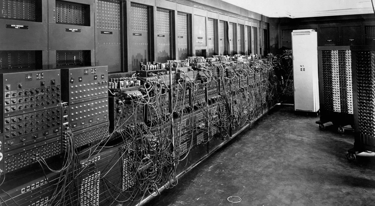

This is the world's first programmable general-purpose computer, ENIAC (Eniac), which was born at the University of Pennsylvania in the US on February 14,1946. ENIAC measures 30.48 meters in length, 6 meters in width and 2.4 meters in height, covering an area of about 170 square meters. It is equipped with 30 operation consoles, weighs 30 long tons, and consists of 17,468 vacuum tubes (electron tubes), 7,200 crystal diodes, 1,500 relays, 70,000 resistors, 10,000 capacitors, 1,500 relays and more than 6,000 switches.It can be seen that its wiring is in a mess, which brings great trouble to the maintenance and repair work.
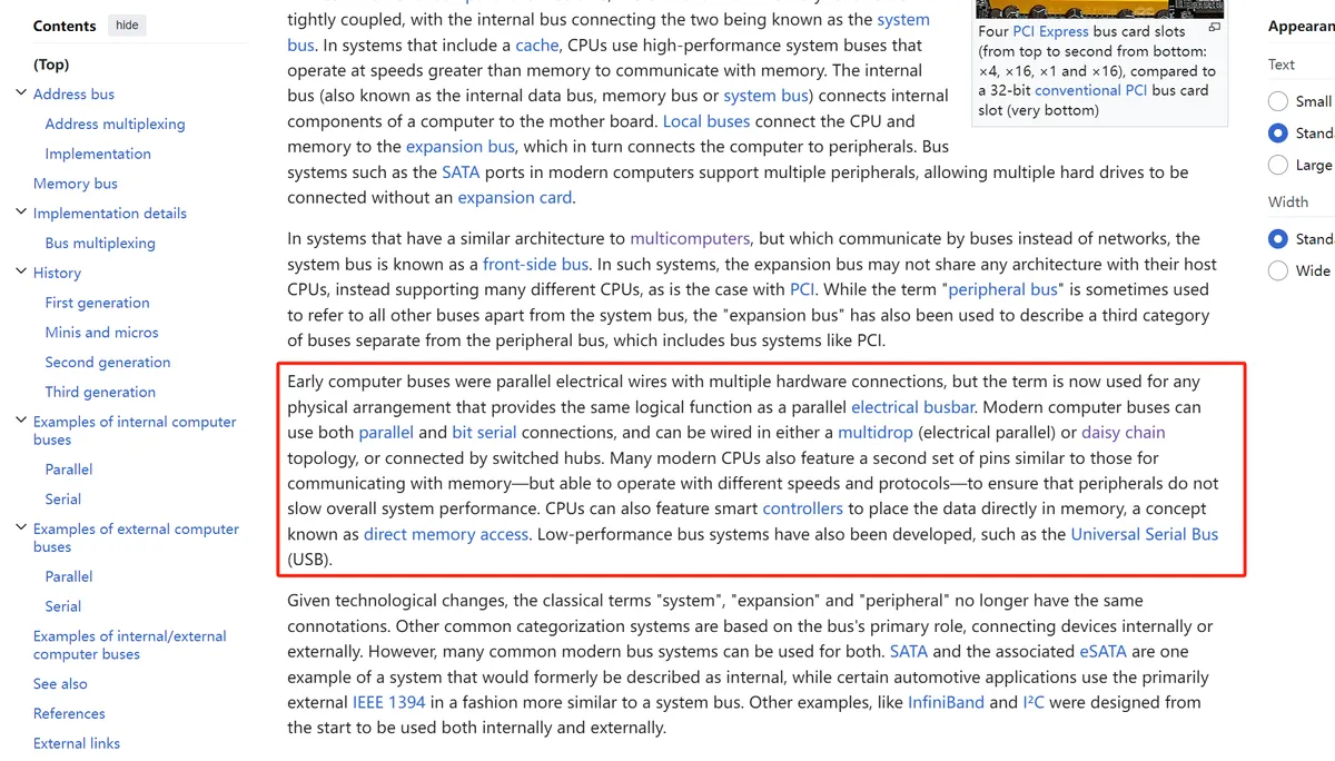
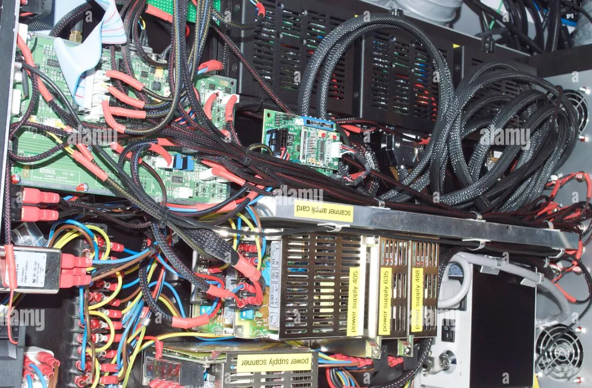
In the subsequent development of computers, people parallelly replicated these large bundles of messy cables onto a common busbar, and this parallel wire row with multiple hardware connections is called a "bus", denoted as BUS (the naming of the word BUS is related to the Latin "omnibus", meaning "for all"). They are also referred to as " digit trunk ", named after power buses or busbars. These buses are used for data transmission between the CPU, memory, and input/output devices. There is almost always one bus dedicated to memory, and one or more separate buses for peripherals.These are accessed via separate instructions, with completely different timings and protocols.
Definition of BUS in Wikipedia:
1.1.2 Modern Meaning of the BUS Bus
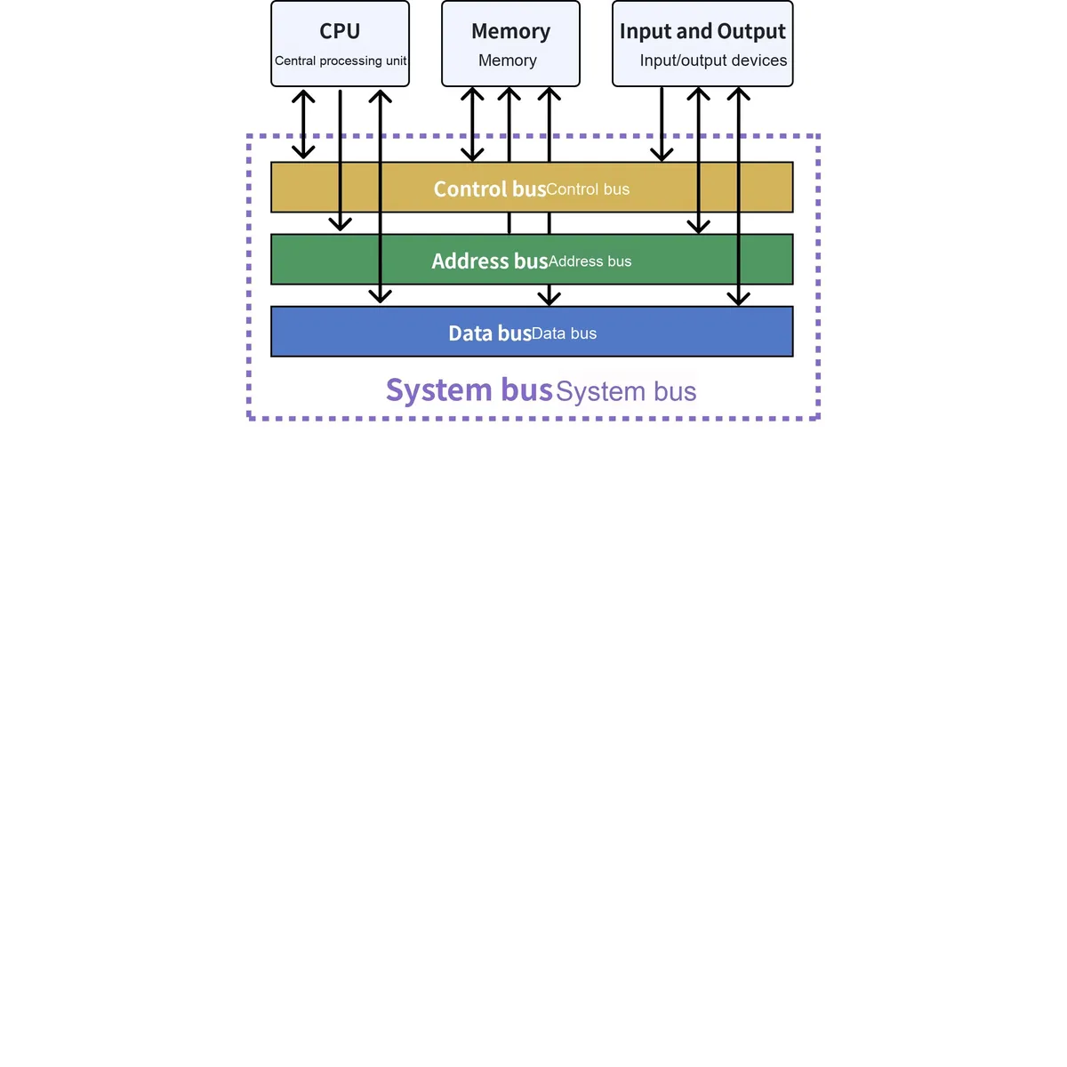
In modern computer architecture, a bus (BUS) is a communication system that transfers data between components inside a computer or between computers. This definition covers all related hardware components (wires, optical fibers, etc.) and software, including Communication Protocol. A computer system generally consists of three main parts: the Central Processing Unit (CPU) that processes data, the memory that stores programs and data to be processed, and I/O (Input/Output) devices that act as peripherals for communication with the outside world.The bus is a common circuit responsible for high-speed data transmission among these three components. Take the computers we use as an example: multi-core CPUs, DDR4 SDRAM for memory, Hard Disk Drive, displays, keyboards and mice all communicate with the CPU via the bus.
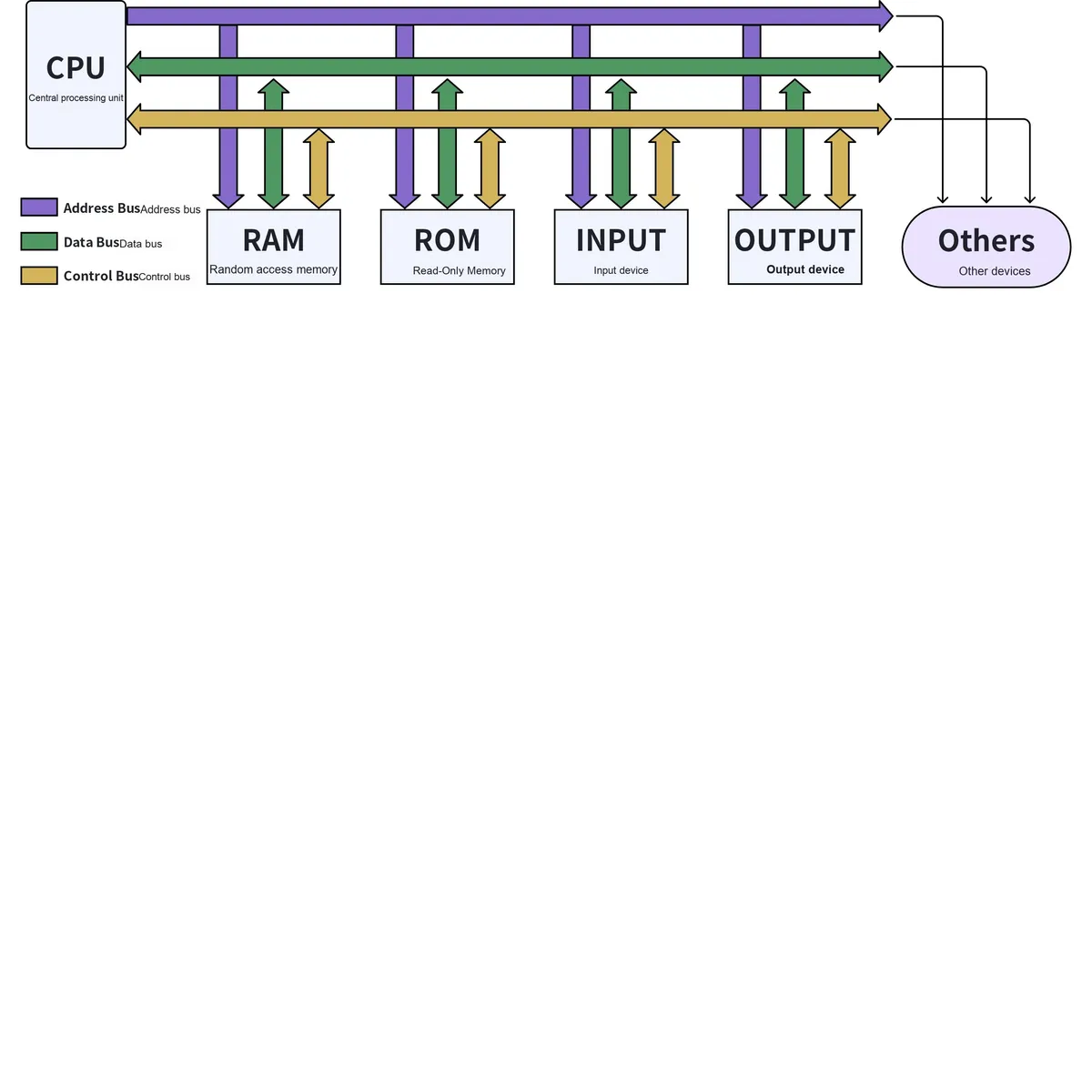
Computers connect various components together via the system bus, enabling information exchange between the internal components of a microcomputer. Under normal circumstances, the signals provided by the CPU need to pass through bus forming circuits to form the system bus. According to the types of information transmitted, computer buses can be divided into data buses, address buses and control buses, which are respectively used to transmit data information, address information and control signals. It can be considered that a computer takes the CPU as the core, with all other components "hanging" on the system bus connected to the CPU.
1.1.3 Features of the BUS Bus
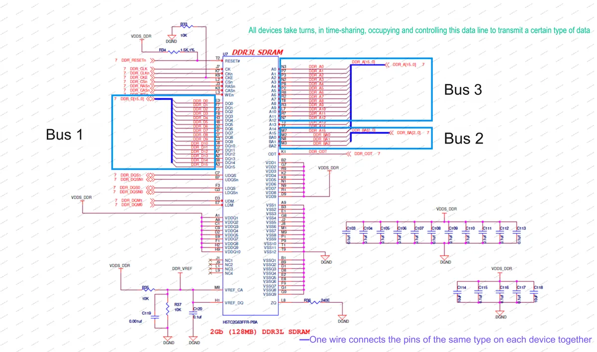
The above is the schematic diagram of DDR3, from which we can see that there are three sets of buses, and each of these three sets is composed of multiple wires.
Returning to the computer example we listed above, a wire connects a corresponding data pin of each device together, so this wire becomes a data line;all devices take turns occupying and controlling this data line in a time-sharing manner to transmit data, so this data line becomes a data bus; there are multiple such data lines, which form multiple data buses, and multiple data buses are referred to as a group (bundle) of data buses. The definitions of the control bus and address bus are similar.
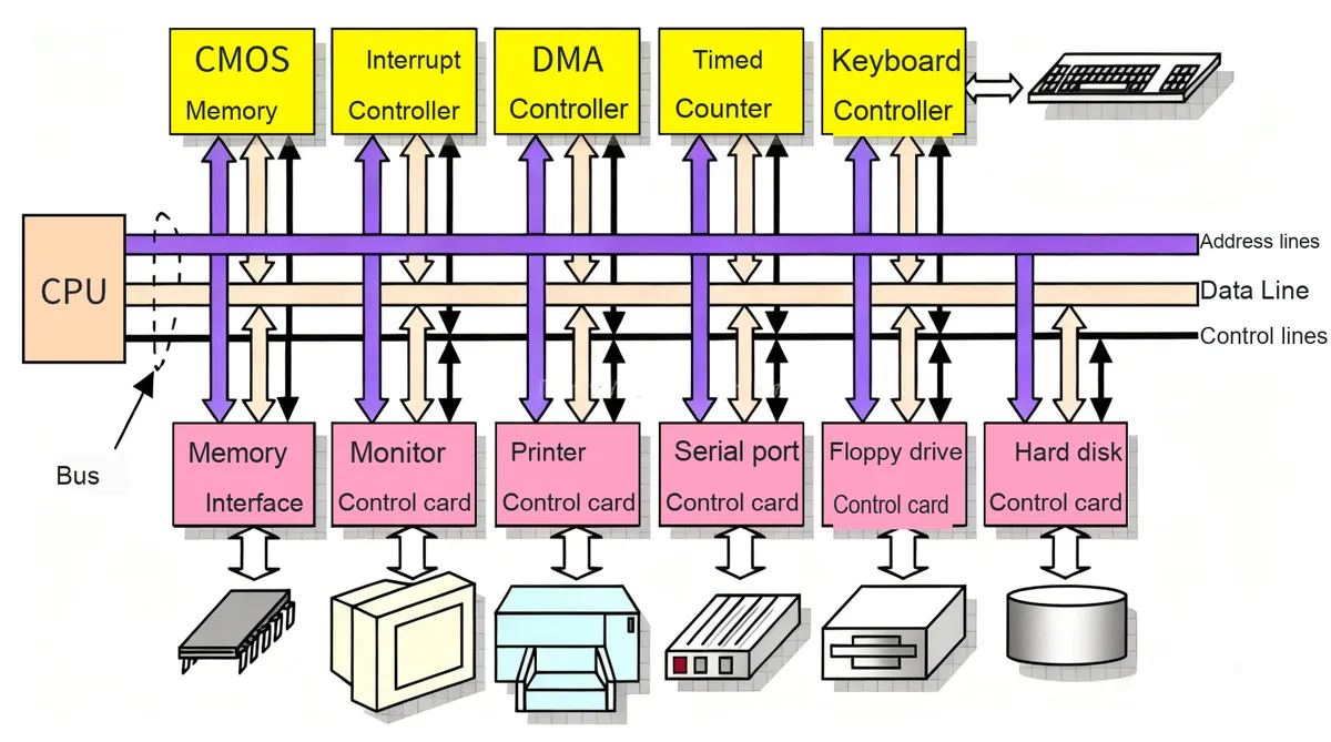
To enable the central processing unit (CPU) of a computer to control and manage peripheral devices such as memory, display, keyboard, mouse, and hard disk, all data lines need to be connected to one common set of lines, all address lines to another separate set, and all control lines to a third distinct set — this forms the data bus, address bus, and control bus, and these three buses are mutually independent of one another.
Each peripheral device takes turns in a time-sharing manner to occupy the data bus and the central processing unit for data transmission, takes turns in a time-sharing manner to occupy the address bus and the central processing unit for address transmission, and takes turns in a time-sharing manner to occupy the control bus and the central processing unit for control signal transmission.
In the scenario of bus communication, the devices participating in communication are clearly divided into two core roles:
- Master: A device that actively initiates bus communication requests, responsible for initiating address transmission and data transmission requests, and also holds the bus occupancy control right; for example, the CPU of Raspberry Pi Pico acts as the master when communicating with on-chip peripherals such as UART and SPI.
- Slave: A device that passively responds to bus communication requests and never initiates communication on its own; it only exchanges data with the host after being selected by the host. For example, the UART peripheral of Pico and external SPI sensors all act as slaves when communicating with the CPU.
From the above, we can summarize the characteristics of the BUS bus as follows:
- A bus is a type of wire used for interconnection and signal transmission that is shared by multiple devices;
- The bus can be applied to scenarios of one master with multiple slaves, multiple masters with one slave, and multiple masters with multiple slaves;
- During bus communication, whether it is a master device or a slave device, only one device can occupy and control the bus to send data externally, and only one device can receive data from outside at the same moment, that is, data transmission is carried out in a one-transmit-one-receive mode (certain broadcast information, handshake protocols, etc. may adopt a one-transmit-multiple-receive mode).
It can be summed up in eight words: multi-pin sharing one line and time-division multiplexing, which means that the pins of the same function of multiple devices are connected to each other, and each device occupies the bus in separate time slots for data transmission.
1.2 I2C Inter-Integrated Circuit Bus
1.2.1 Introduction to I2C Bus
IIC (Inter-Integrated Circuit) is the abbreviation of IICBus, whose Chinese name is integrated circuit bus. It was developed by Philips in the 1980s to enable motherboards, embedded systems or mobile phones to connect low-speed peripheral devices. As a serial communication bus, it only requires two wires to realize communication between multiple digital devices. Featuring few occupied pins, simple hardware implementation and strong scalability, it is widely used in scenarios where a single-chip microcomputer on a single circuit board needs to communicate with multiple external sensors.
All of the following sensor modules communicate with the microcontroller via the IIC protocol
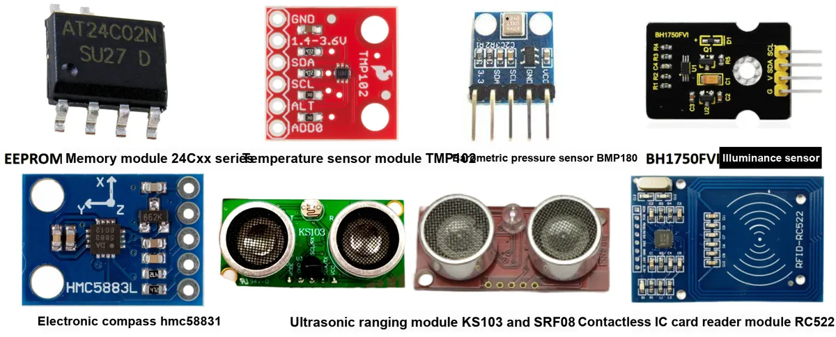
The IIC bus has only two signal lines in total: one is the bidirectional serial data line SDA, and the other is the bidirectional serial clock line SCL. Both SDA and SCL are bidirectional; the data lines of all devices on the IIC bus are connected to the SDA line, and the clock lines of all devices on the IIC bus are connected to the SCL line.
In the I2C bus protocol, communication nodes (sensors or microcontrollers) mounted on the bus are usually identified by 7 address bits, which function like unique identification numbers. Each communication node can act as a master that initiates communication or a slave that responds passively when addressed by the master during communication. One master can communicate with multiple slaves, and multiple masters can also communicate with multiple slaves simultaneously.
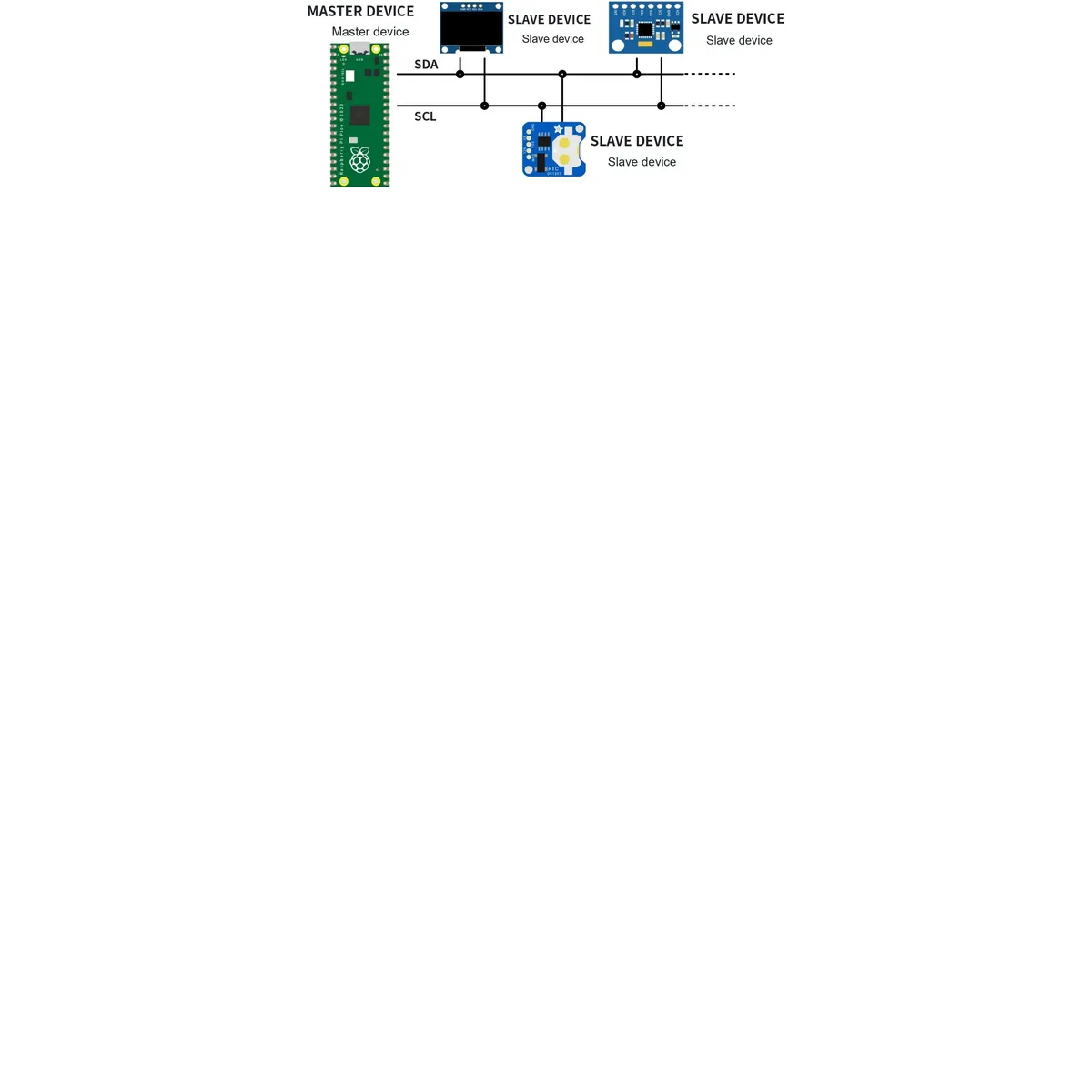
Multiple devices can be connected to the same SDA and SCL lines in a "daisy-chain" configuration. Since each device on the bus has a unique address, the master device can select which specific device to communicate with.
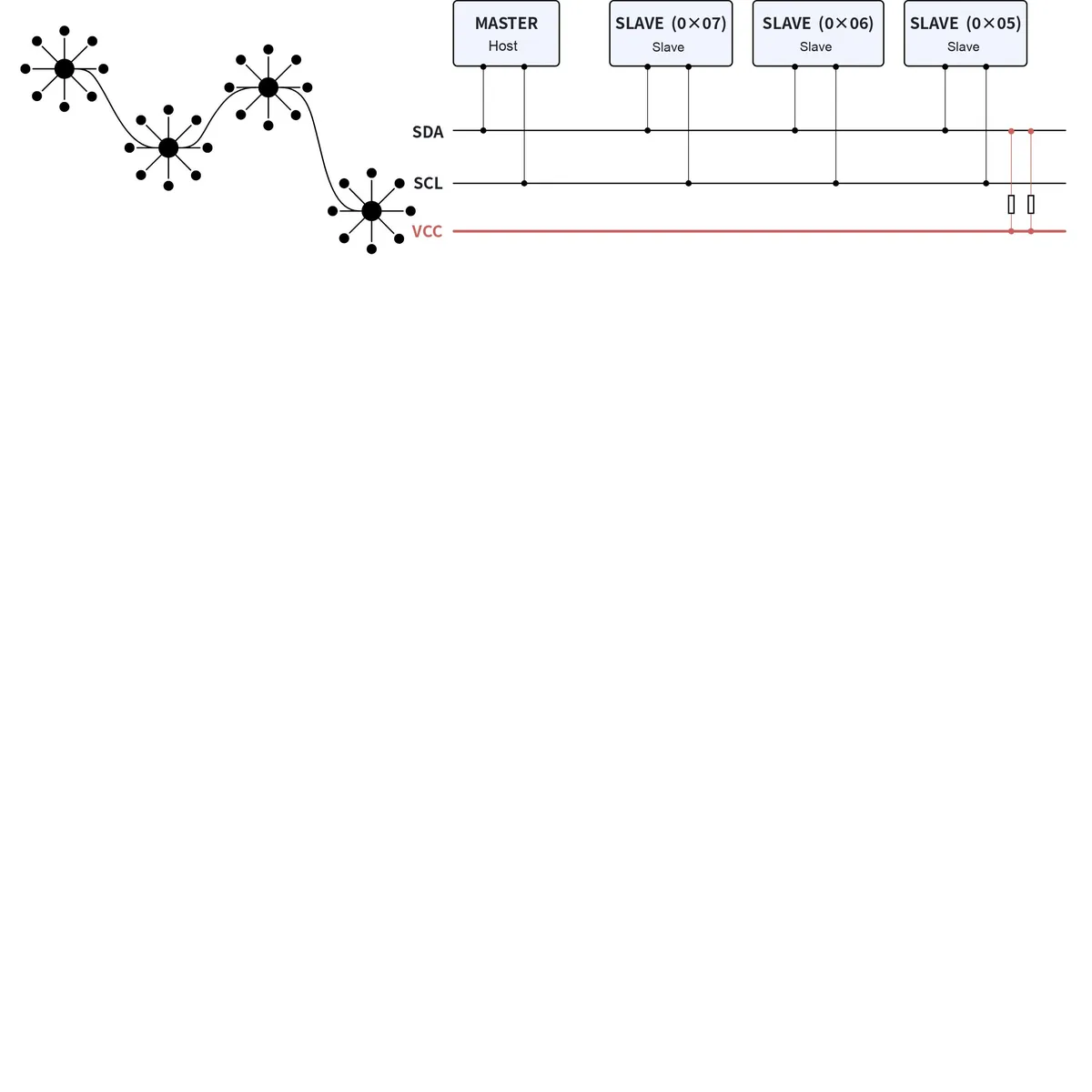
Daisy-chain Topology
At its most fundamental, the term "daisy chain" refers to a garland made by stringing numerous daisies together; in its early days, it was also known as the hand-in-hand connection method, where one person can hold the hands of at most two other people via their two arms (the equivalent of a single chip being able to connect to no more than two other chips via two transmission lines). Later, when the concept evolved into the field of electrical and electronic engineering, a daisy chain came to denote a wiring scheme: for instance, Device A is connected to Device B via a cable, Device B is then connected to Device C via another cable, and Device C is connected to Device D via yet another cable. This connection method does not form a mesh topology, and only adjacent devices can communicate directly — in the example above, Device A cannot communicate directly with Device C, and must instead relay communications through Device B. This approach also does not create any loops.
However, this topology is difficult to implement in PCB design and has gradually evolved into the structure shown in the above figure: first, route a main trunk according to the layout positions of the IIC master device and each IIC slave device, and then route traces from the main trunk to each slave device.
1.2.2 Development History of the I2C Bus
Originally, the I2C bus specification was invented by Philips Semiconductors in 1982, and is widely used to connect low-speed peripheral integrated circuits to processors and microcontrollers for short-distance on-board communication. The original specification only allowed 100kHz communication and provided only 7-bit addresses, limiting the number of devices on the bus to 112 (there are also several reserved addresses that are never used for valid I2C addresses).
After Philips invented the I2C-bus, on the one hand, it developed numerous chips with I2C-bus functionality based on this technology; some of these I2C-bus-enabled chips were for Philips' own use, while the rest were sold to other chip application manufacturers. On the other hand, Philips licensed the patented I2C-bus technology to other chip manufacturers, who integrated this technology into their own chips to equip their products with I2C-bus capabilities as well.Since the mid-1990s, a number of competitors including Siemens, NEC, Texas Instruments, STMicroelectronics, and Motorola have launched compatible I2C products onto the market.
Whether Philips sells I2C-bus chips or I2C-bus patented technologies to external parties, it always provides a complete set of technical documentation and application guidelines simultaneously, so that devices with I2C-bus functions have a unified standard, which is the I2C Bus Specification. In 2016, the semiconductor division under Philips was spun off into an independent new company named NXP Semiconductors, which is now the stakeholder of the I2C Bus Specification.
You can view the current IIC bus specification at the following link:
https://www.nxp.com/docs/en/user-guide/UM10204.pdf
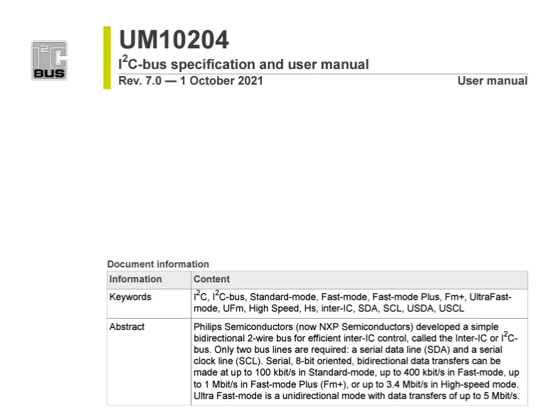
Since October 10,2006, the original I2C patent has expired, so the I2C bus can be used freely without paying patent royalties, though manufacturers still need to pay to obtain I2C slave device addresses assigned by NXP. The I3C specification launched by the MIPI Alliance in 2017 had NXP's participation and contributions. MIPI I3C offers backward compatibility with I2C, higher speed, lower power consumption, and a royalty-free version.
You can refer to the table below for the version changes of the I2C bus:
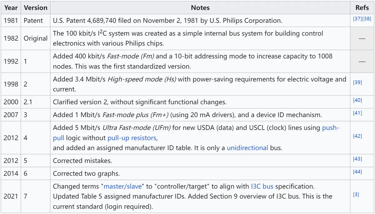
The key changes are as follows:
- First Release Version: Originally first released by Philips in 1982.
- V1.0-1992: removed the content related to slave address software programming; deleted the detailed description of the Low-speed mode; added the Fast-mode with a bit rate up to 400 Kbit/s, which is backward compatible with the 0~100 Kbit/s bit rate of the Standard-mode.
- V2.0-1998: The I2C bus has become a global standard, licensed to more than 50 companies and implemented in over 1000 different ICs. This version adds a High-speed mode with a bit rate of up to 3.4 Mbit/s, which is backward compatible with the Fast-mode and Standard-mode; it adds support for low-voltage devices of 2V or lower while remaining compatible with high-voltage devices; it removes the 0.6V/6mA requirement for the Fast-mode output stage; it adds content specifying that new devices use bus voltage-dependent levels instead of fixed levels; and it adds the application of bidirectional level translators.
- V2.1-2000: Added the function of extending the clock signal SCLH after the repeated start condition in high-speed mode; relaxed some timing parameter requirements in high-speed mode.
- V3.0-20070619: Added Fast-mode Plus, which boosts the drive strength by 10 times and increases the bit rate from 400 Kbit/s (Fast-mode) to 1 Mbit/s, catering to application requirements for longer buses and/or higher speeds.
- V4.0-20120213: Added the unidirectional I2C bus and Ultra Fast-mode with a bit rate up to 5 Mbit/s.
- V6.0-2014: Modified the calculation method of the pull-up resistor.
- V7.0-2021: Updated the list table of I2C chip manufacturer name IDs; updated the term "master/slave" to "controller/target"; added content of the MIPI I3C specification, with an I3C bit rate up to 10 Mbit/s, providing a flexible upgrade solution for I2C and SPI.
1.2.3 Introduction to I2C Protocol
Note that most of this document only describes the I2C protocol in standard mode, and does not cover the minor differences between the I2C protocol in fast mode, fast mode plus, high-speed mode and ultra-fast mode and that in standard mode. Interested readers can refer to the original protocol document by themselves:
https://www.nxp.com/docs/en/user-guide/UM10204.pdf
Before introducing the I2C bus protocol, we need to first understand several related concepts of the I2C protocol:
- Transmitter: A device that transmits data to the I2C bus during this transmission, which can be either a master or a slave.
- Receiver: A device that receives data from the I2C bus during this transmission, which can be either a master or a slave.
- Host: A device that initiates transmission, generates clock signals, and terminates transmission
- Slave: A device addressed by the master
- Arbitration: A selection procedure designed to ensure that when multiple hosts attempt to control the bus simultaneously, only one host is granted bus control and the data on the bus remains uncorrupted.
- Synchronization: The process of synchronizing the clock signals of two or more devices
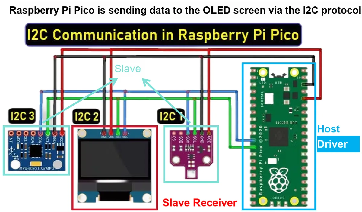
Here, we divide the I2C protocol into two levels: the physical layer and the protocol layer: The physical layer specifies the characteristics of the mechanical and electronic functional parts in the communication system, ensuring the transmission of the original data source in the physical medium. The protocol layer mainly specifies the communication logic, unifying the data packaging and unpacking standards of both the sending and receiving parties. Simply put, the physical layer specifies whether we communicate with our mouths or limbs, and the protocol layer specifies whether we communicate in Chinese or English.
1.2.3.1 Physical Layer of the I2C Protocol
1.2.3.1.1 Communication Interface of the I2C Protocol
IIC is a half-duplex synchronous serial communication protocol. Compared with UART and SPI, it only requires two wires, SCL and SDA, along with the corresponding pull-up resistors.
- SCL Serial Clock Line: The signal line used for clock transmission in I2C communication, which is usually driven by the master device. SCL adopts an open-collector or open-drain output configuration, which means that the I2C bus can only pull SCL down to logic 0, and cannot force SCL to be pulled up to logic 1.
- SDA Serial Data Line: A signal line used for data transmission in I2C communication, which is typically driven by the master device. SDA adopts an open-collector or open-drain output configuration, which means that the I2C bus can only pull SDA down to logic 0, and cannot force SDA to be pulled up to logic 1.
- Pull-up resistor: used to provide a high logic level for the bus, with a default value ranging from 1 to 5.1 kΩ; common selections are 5.1 kΩ(for 5V scenarios) or 4.7 kΩ(for 3.3V scenarios)
It should be noted that most sensor modules or OLED display modules sold on the market are equipped with pull-up resistors for their I2C interfaces. If multiple electronic modules are connected to our I2C bus, it is necessary to remove or adjust the pull-up resistors of some modules to ensure that the equivalent pull-up resistance after parallel connection is 4.7kΩ.
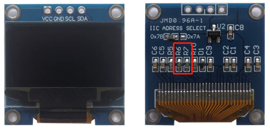
The image above shows a commonly used OLED display module, where R6 and R7 function as pull-up resistors.
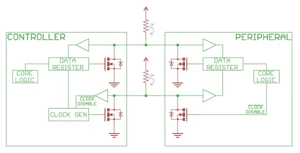
The following figure illustrates the process of the IIC bus being pulled low and pulled high.
- Pull-down: The logic circuit of the device controls the FET to turn on, and the bus is connected to GND through the conducting FET so as to be pulled low.
- Pull-up: The logic circuit of the device controls the FET to turn off, and the bus is connected to VDD via the pull-up resistor Rp, thus being pulled up.
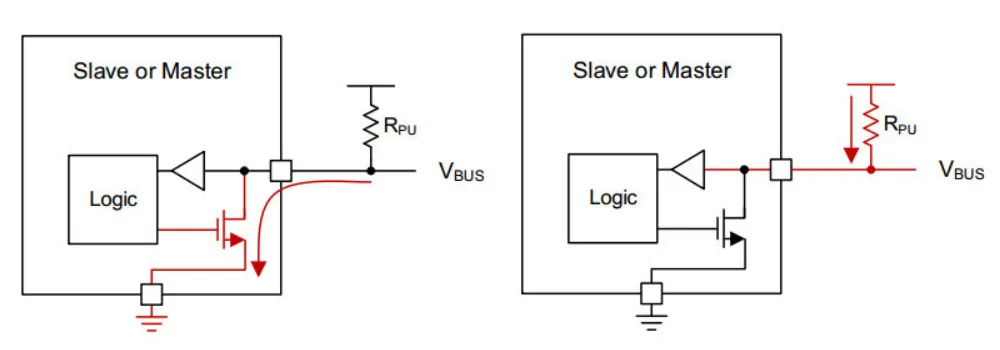
In I2C and other bus-based communication physical layers, open-collector (OC gate) and open-drain (OD gate) are key circuit structures for implementing "bus sharing, level shifting, and wired-AND logic".
When the open-collector output is turned off, it is in a floating state; when it is turned on, it is grounded. The open-drain output requires an external pull-up resistor to achieve a high level.
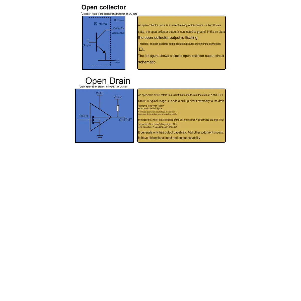
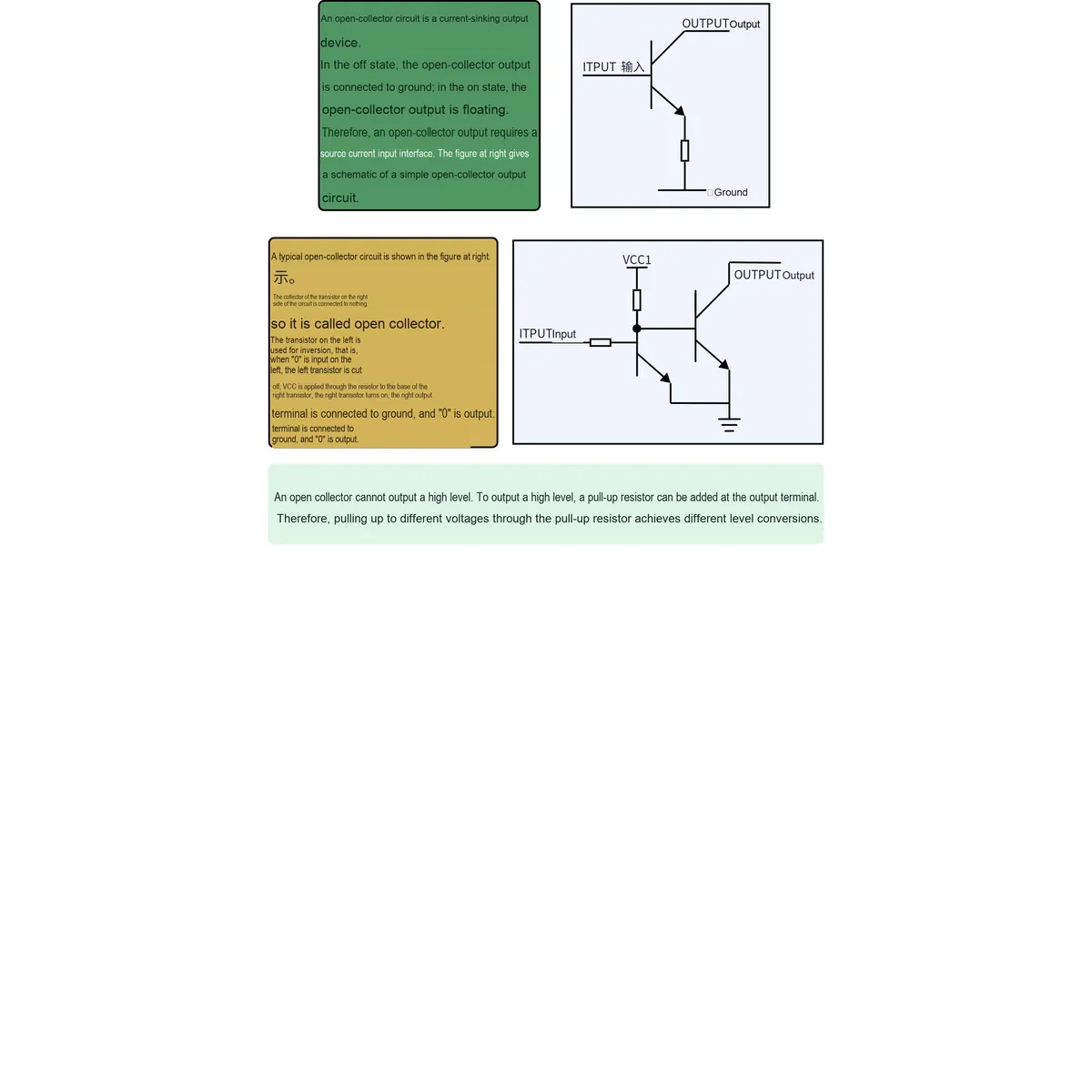
The I2C physical layer uses open-collector output, requiring an external pull-up resistor. For the circuit in the diagram: when the input is "0", the right-side transistor turns on, pulling the output to ground to register a "0"; when the input is "1", the output is pulled up to a "1" level, supporting level translation.
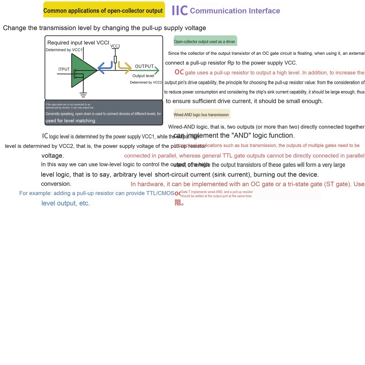
Open-collector circuits have three types of applications:
- Level conversion can be achieved by modifying the pull-up power supply;
- External pull-up for enhanced driving capability;
- Parallel connection of multiple OC gates combined with a pull-up resistor implements wired-AND logic for the bus, supporting multi-device sharing.
Open-drain circuits take MOSFET as the core and are a common structure for I2C. In the diagram, the drain is externally connected to a pull-up resistor: when the MOSFET is turned on, it outputs a "0"; when it is turned off, the pull-up resistor pulls the output to a "high" level. Multiple open-drain pins can be connected in parallel to form a bus (such as I2C 's SDA / SCL), enabling multi-device sharing and level shifting.
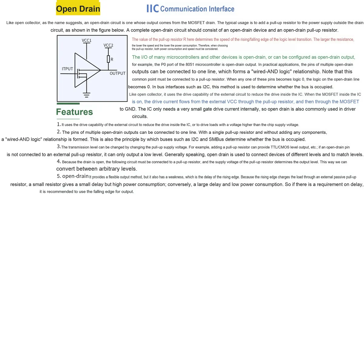
Here, the reason for using an open-collector or open-drain configuration is to prevent overheating or damage to devices caused by short circuits that may occur when performing "wired-AND" on the bus. If a push-pull structure is designed, when some devices output a high level while others output a low level on the SDA or SCL bus at the same time, a short circuit will occur between the pull-up switch transistor connected to the power supply and the pull-down switch transistor connected to the ground, resulting in excessive switch power consumption (if current limiting protection is provided) or burnout of the device.
The following figure is a schematic diagram of short circuit of push-pull output:
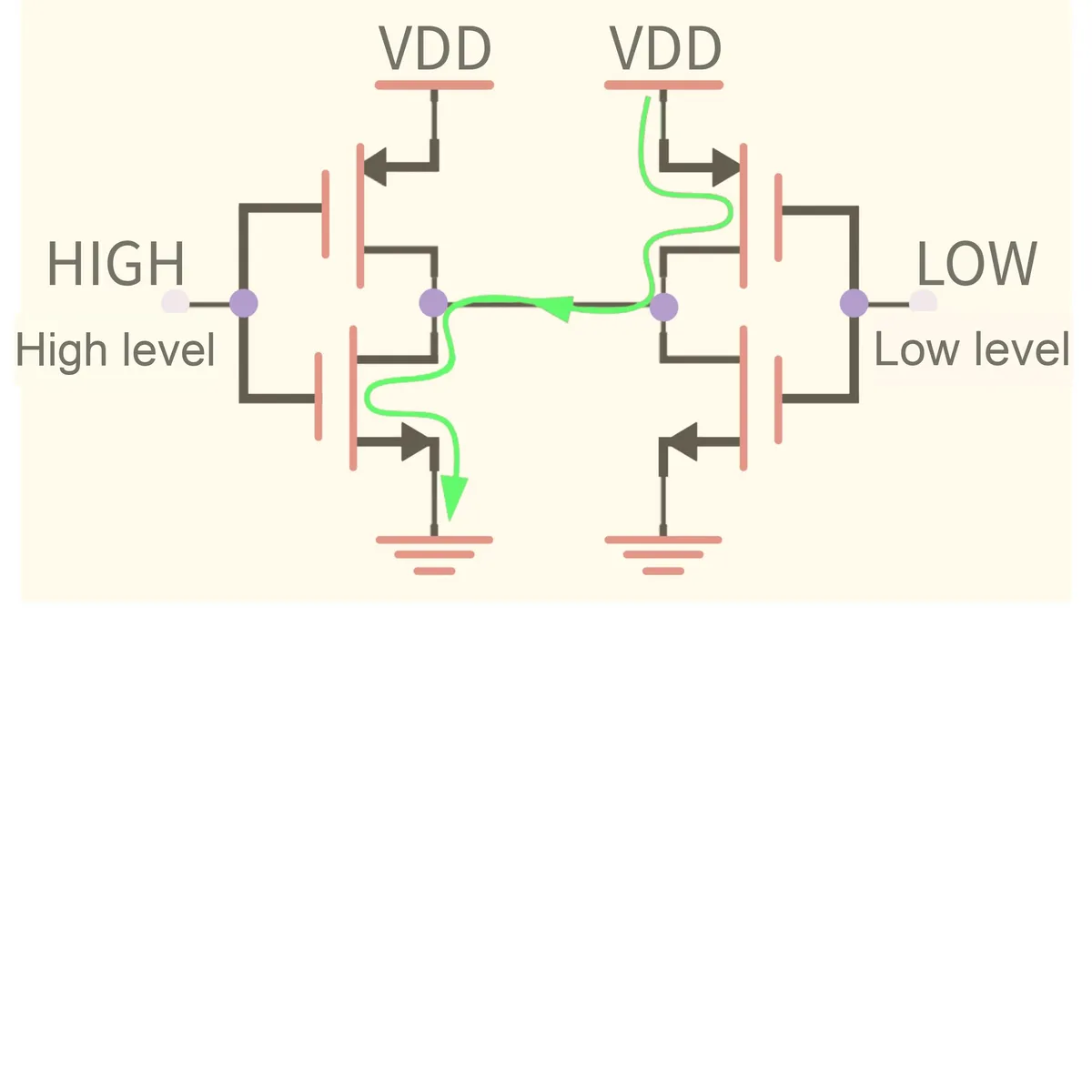
By means of open-collector or open-drain configuration, when one device attempts to drive the line to a high level while another device tries to pull it low, no bus contention will occur, thus eliminating the possibility of driver damage or excessive power consumption in the system. An external pull-up resistor is connected to the bus to restore the signal to a high level when no device is driving the signal low.
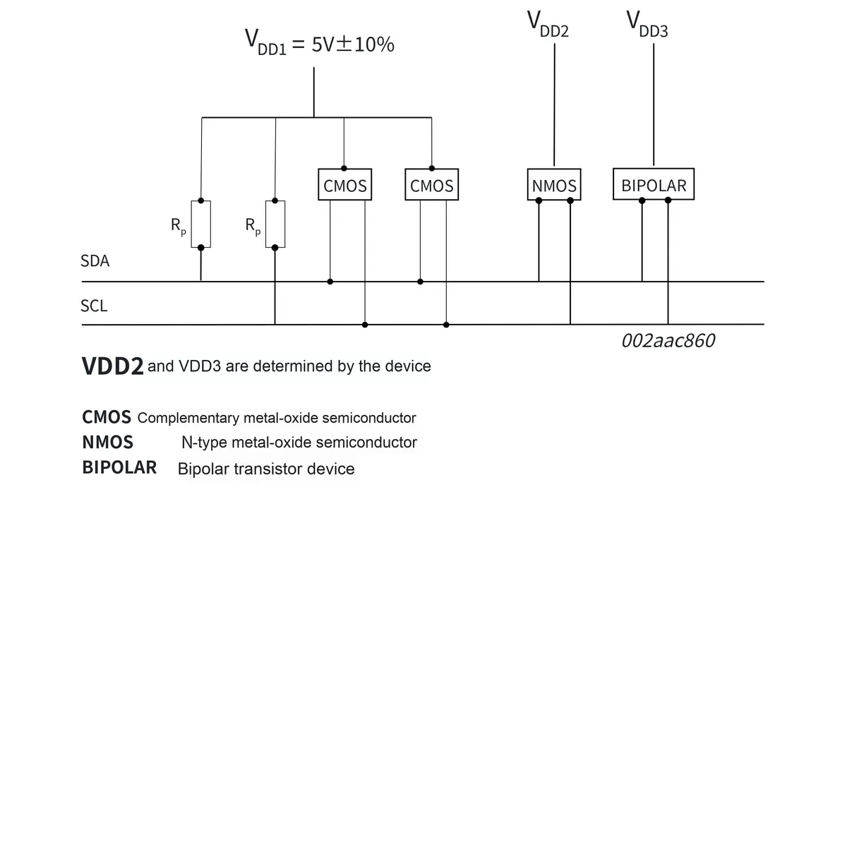
Meanwhile, devices connected to the IIC bus that operate at different supply voltages can be compatible with each other by means of open-collector or open-drain configuration:
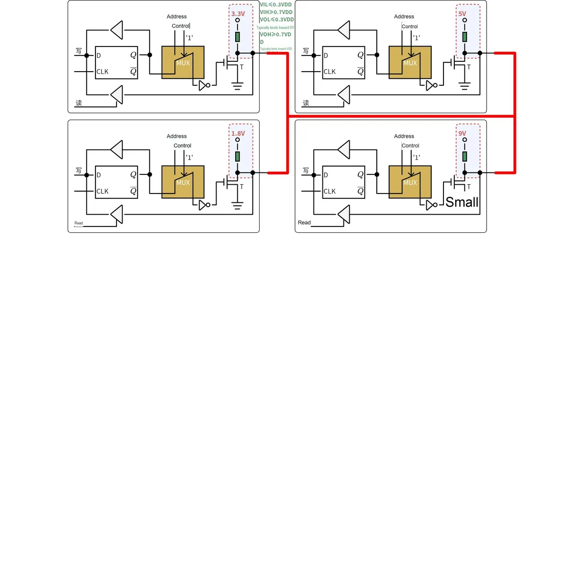
In addition, when we perform communication, usually only a few devices are involved in the communication. The remaining idle devices are pulled to a high-impedance state, which is equivalent to an open circuit, due to the adoption of OD (Open Drain) or OC (Open Collector) configurations. Only the activated devices on the entire I2C bus will communicate normally without interfering with other devices.
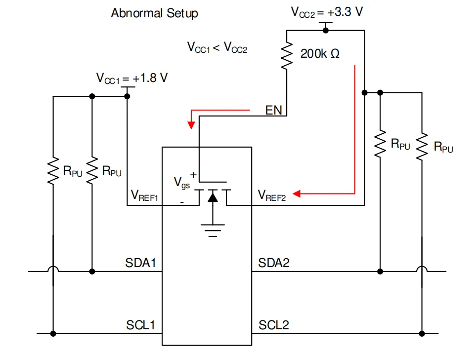
Meanwhile, if there is an excessively large difference in the supply voltage of devices connected to the same I2C bus (e. g., 5V and 2.5V), communication between the two devices may fail. In this case, we can use the PCA9306 bidirectional I2C bus and SMBus voltage level translator to make the connections shown in the following figure, so as to ensure normal communication between the two devices.
1.2.3.1.2 Master-Slave Assignment and Transmit-Receive Relationship in I2C Protocol
Devices transmit information via two buses, namely Serial Data (SDA) and Serial Clock (SCL). Each device (including microcontrollers, LCD drivers, memories, keyboard interfaces, etc.) has a unique address and can operate as either a transmitter or a receiver, depending on its function. For instance, an LCD driver can only act as a receiver, while a memory can function as both a receiver and a transmitter. During data transmission, some devices can serve as masters, while others can act as slaves.A master is a device that initiates data transfers on the bus and generates clock signals to enable such transfers; any addressed device is regarded as a slave.
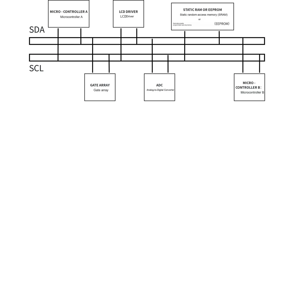
Taking the I2C bus circuit connected to two microcontrollers as shown in the figure as an example, we illustrate the relationship between the master and the slave as well as the relationship between the transmitter and the receiver when data is transmitted between devices.
1. Data transmission between single-chip microcomputers
A single-chip microcontroller can both receive and transmit data. When a given single-chip microcontroller is receiving data, it acts as a receiver; conversely, when it is transmitting data, it functions as a transmitter. That is, in the I2C protocol, the roles of receiver and transmitter depend solely on the direction of data transfer, and these two roles frequently switch during a communication session.
Meanwhile, the single-chip microcomputer can act as a master that initiates data transmission on the bus and generates clock signals to enable the transmission, and can also serve as a passively addressed slave; the master-slave role of the single-chip microcomputer can be changed according to transmission requirements.
- When Microcontroller A acts as the host and Microcontroller B acts as the slave:
- Microcontroller A sends a message to Microcontroller B:
- MCU A (master) addresses MCU B (slave)
- Single-chip microcontroller A (master/transmitter) sends data to single-chip microcontroller B (slave/receiver)
- Microcontroller A terminates the transmission
- Microcontroller A receives information from Microcontroller B:
- MCU A (master) addresses MCU B (slave)
- Microcontroller A (master/receiver) receives data from Microcontroller B (slave/transmitter)
- Microcontroller A terminates the transmission
- Microcontroller A sends a message to Microcontroller B:
- When MCU B acts as the host and MCU A acts as the slave:
- Microcontroller B sends a message to Microcontroller A:
- MCU B (master) addresses MCU A (slave)
- MCU B (master/transmitter) sends data to MCU A (slave/receiver)
- MCU B terminates the transmission
- Microcontroller B receives information from Microcontroller A:
- MCU B (master) addresses MCU A (slave)
- Microcontroller B (master/receiver) receives data from Microcontroller A (slave/transmitter)
- Microcontroller B terminates the transmission
- Microcontroller B sends a message to Microcontroller A:
2. Data transmission between microcontroller A and RAM
A microcontroller can both receive and transmit data, acting as the master that initiates communication and provides the clock signal. A RAM chip can also receive and transmit data, but it cannot initiate communication or supply a clock, functioning solely as a slave device. In this setup, the master-slave roles remain fixed, while the roles of receiver and transmitter are variable.
- Microcontroller A sends information to RAM:
- MCU A (master), addressing RAM (slave)
- Single-chip microcontroller A (master/transmitter) transmits data to RAM (slave/receiver)
- Microcontroller A terminates the transmission
- Microcontroller A receives information from RAM:
- Microcontroller Unit A (controller) addresses RAM (target)
- MCU A (master/receiver) receives data from the RAM (target/transmitter)
- Microcontroller A terminates the transmission
3. Data transmission between the microcontroller and the LCD screen
The single-chip microcomputer is used as the master device for data transmission, while the LCD screen only functions as the slave device for data reception. In this case, the roles of master and slave are fixed, as are the roles of the receiver and transmitter, leading to unidirectional data transmission.
- Microcontroller A sends a message to the LCD:
- MCU A (master) addresses the LCD (slave)
- MCU A (master/transmitter) sends data to the LCD (slave/receiver)
- Microcontroller A terminates the transmission
- Microcontroller A receives information from the LCD:
- Cannot be implemented because the LCD can only receive data
1.2.3.1.3 Physical Topology Structure of the I2C Protocol
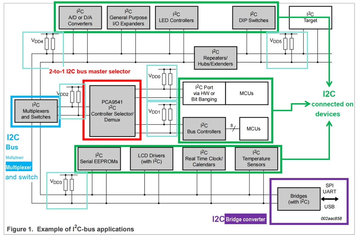
1. Single master and multiple slaves
In an I2C communication bus, multiple I2C communication devices can be connected, each device connected to the bus has a unique address, and the host can use this address to access different devices. The I2C master must first send the address of the I2C slave device it intends to communicate with, and only after receiving a response can it carry out data communication with the slave device.
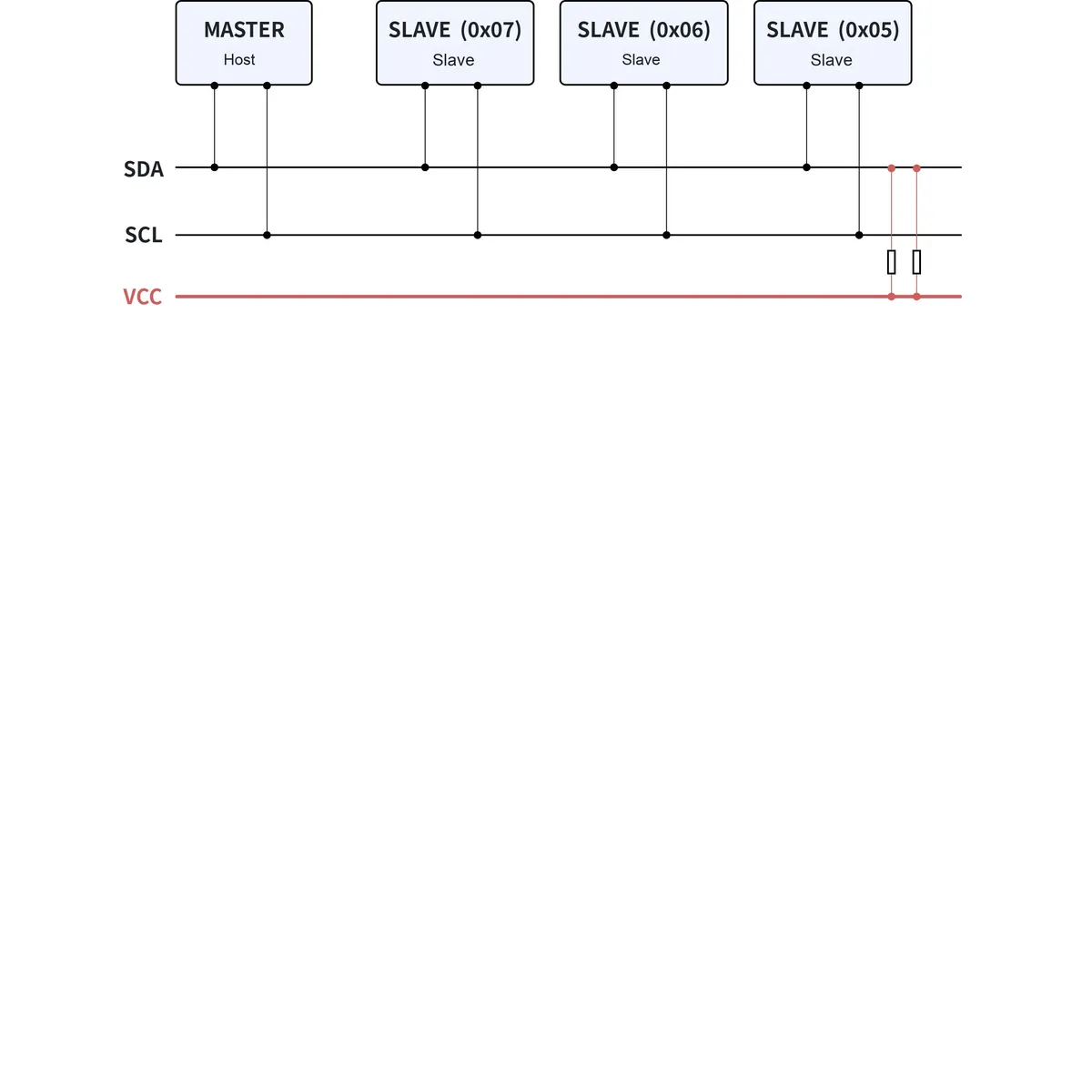
2. Multi-master and Multi-slave
I2C is equipped with collision detection and arbitration circuits. When multiple hosts use the bus simultaneously, an arbitration mechanism is adopted to determine which device will occupy the bus to prevent data conflicts. Meanwhile, to avoid contention, each host must check the status of the SDA line before transmitting data.
- If the SDA line is at a low level, it means that another master device can control the bus, and the master device should wait to send a message
- If the SDA line is at a high level, the message can be transmitted safely
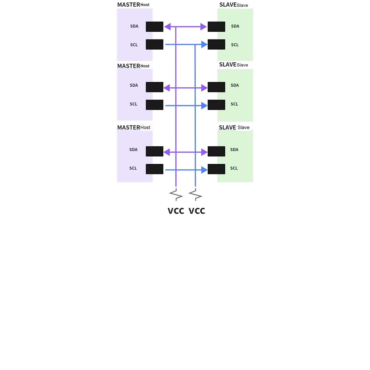
1.2.3.1.4 Communication Rate and Number of Devices of the I2C Protocol
Referring to the definition on Wikipedia, the data transfer rates on the I2C bus can reach up to 100 Kbit/s in standard mode, 400 Kbit/s in fast mode, 1 Mbit/s in fast mode plus, 3.4 Mbit/s in high-speed mode, and 5 Mbit/s in ultra-fast mode:
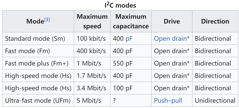
The IIC protocol itself does not strictly limit the number of devices connected to the I2C bus (theoretically, the number of devices that can be connected to IIC depends on the maximum address space that can be represented; in the 7-bit address mode, subtracting the unavailable 0x00 address, it can theoretically support 2^7 -1 = 127 devices), but it specifies the limit value for bus capacitance.
The number of devices connected to the I2C bus is limited by the bus capacitance limit of 400 pF: Capacitance inevitably exists in the semiconductor structures connected to the signal lines, and the more nodes there are, the larger the capacitance will be. Meanwhile, the I2C protocol requires external pull-up resistors for the SCL and SDA pins (there are also resistors and capacitors on the connected lines), and these resistors and capacitors will generate an RC delay effect, which slows down the signal rise time.Given that the I2C protocol stipulates that the rise time of SCL and SDA (i. e., the time taken to transition from logic 0 to logic 1) must be less than 1000 ns, the number of devices connected to the I2C bus inevitably has to be limited.
RC time constant t = R*C
- In an RC circuit, the capacitor voltage Uc always decays monotonically to zero exponentially from its initial value Uc (0), and its time constant τ is:.
- For a quantity that decays exponentially, the time required for its amplitude to decay to 1/e times (approximately 0.37 times) its initial value is defined as the time constant.
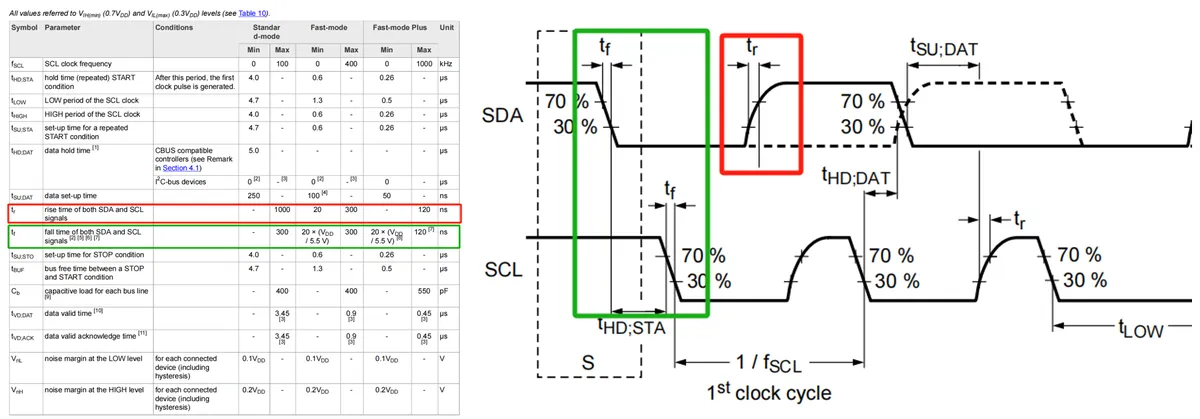
1.2.3.1.5 Logic Level of I2C Protocol
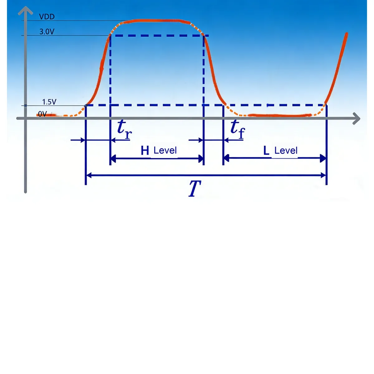
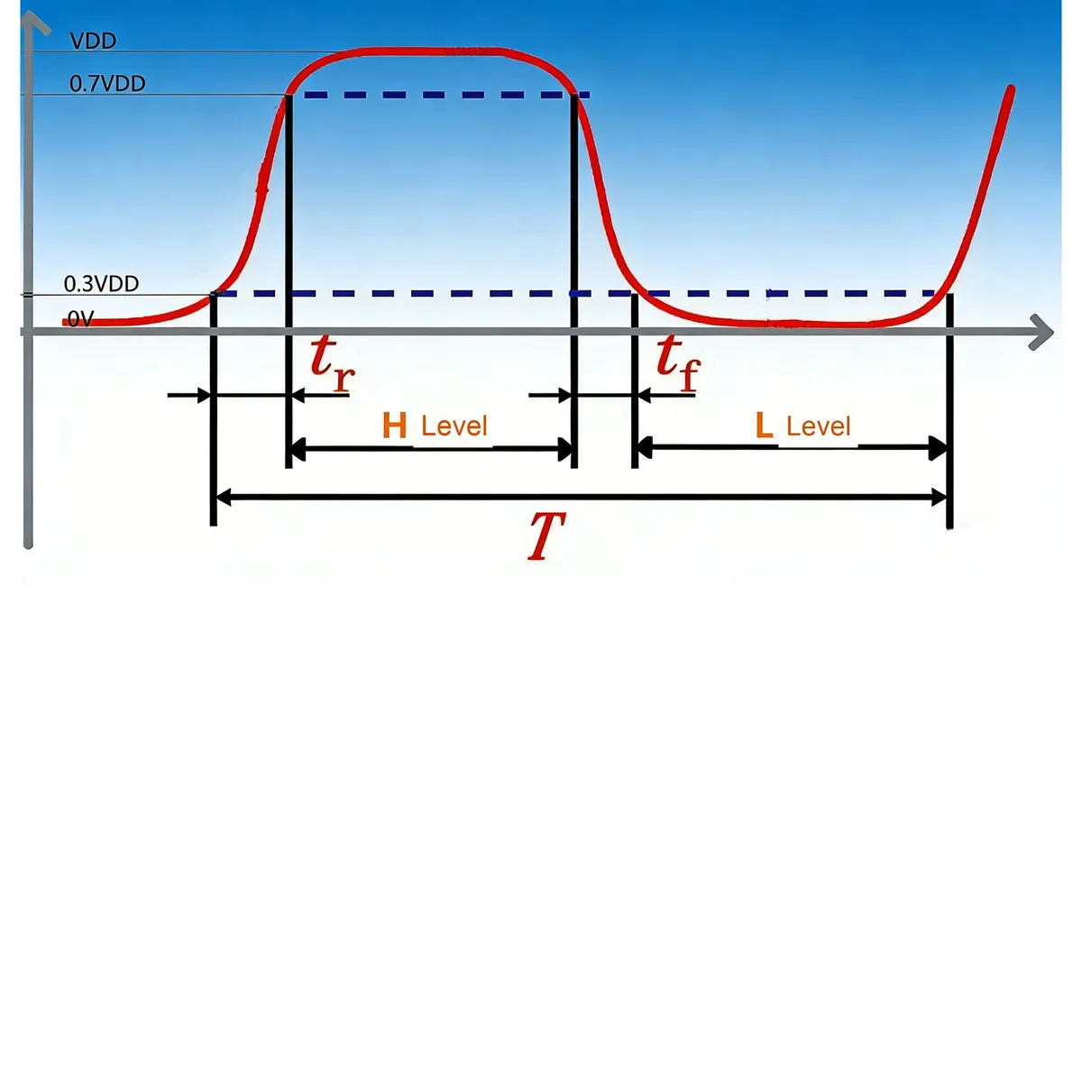
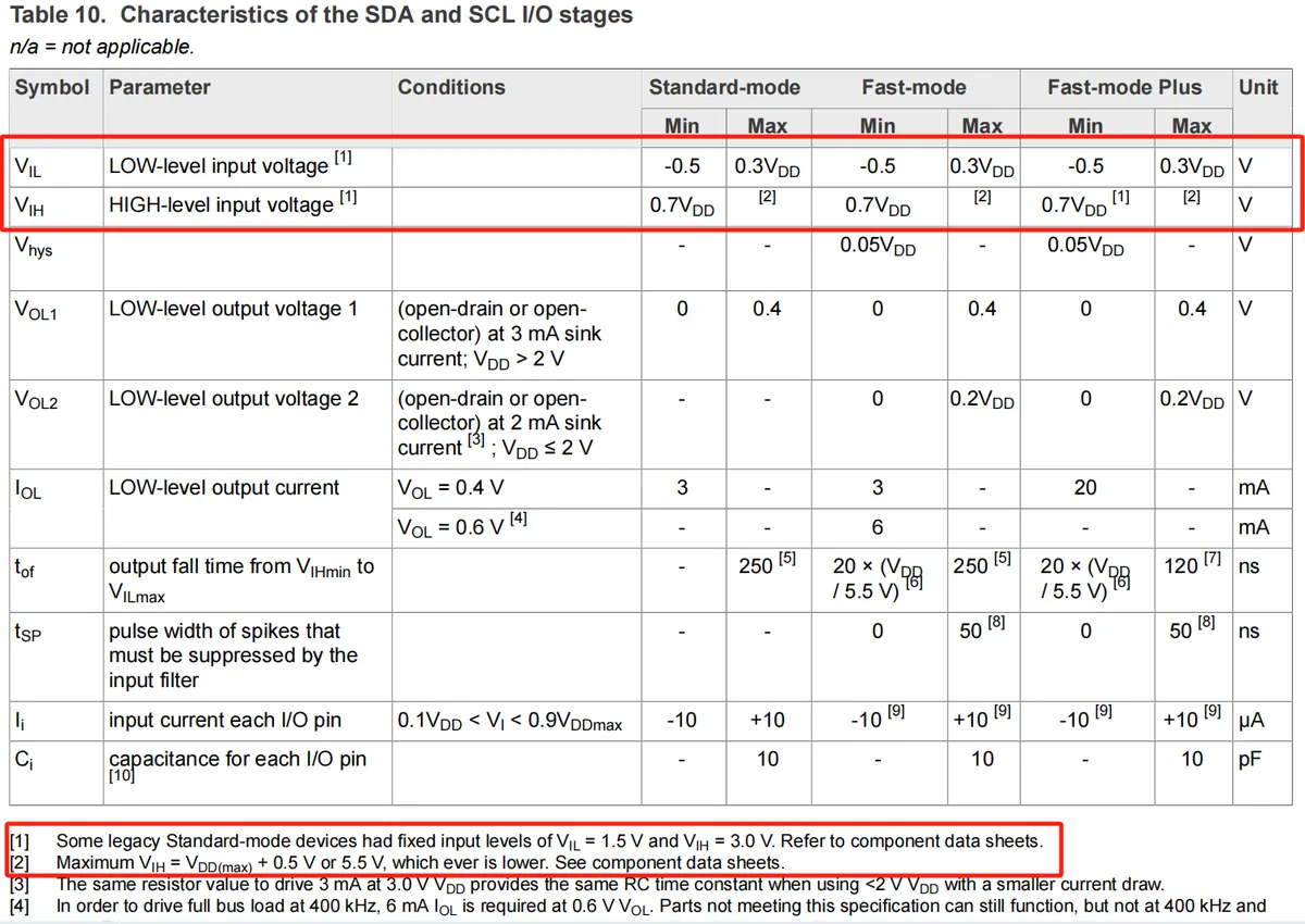
Devices connected to the I2C bus include CMOS devices, NMOS devices, BIPOLAR devices, etc. Their supply voltages vary, and the level thresholds for logic "0"(low) and logic "1"(high) on the SDA and SCL signal lines are also not fixed. The I2C specification sets forth the following two provisions:
- For traditional devices, the input levels are fixed: VIL ≤ 1.5V, VIH ≥ 3.0V
- For new-type devices, the input level depends on the power supply voltage VDD: VIL ≤ 0.3VDD, VIH ≥ 0.7VDD
1.2.3.1.6 Electrical Characteristics of the I2C Protocol
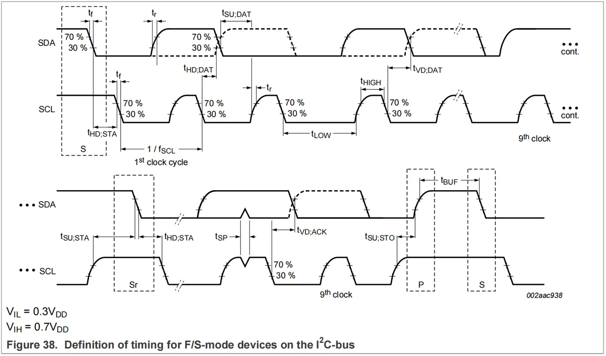
It mainly specifies the electrical characteristics of signals, including signal rise time, signal fall time, start signal hold time, etc. For details, please refer to the figure below:
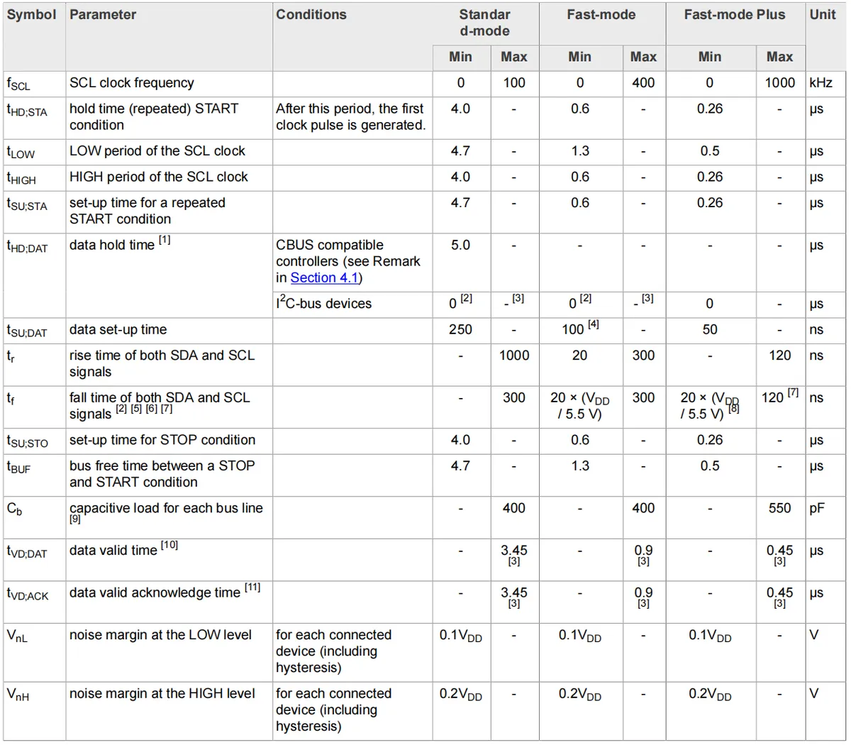
This table lists the relevant parameters of the I2C protocol in standard mode.
1.2.3.2 Protocol Layer of the I2C Protocol
1.2.3.2.1 Data Frame Format of the I2C Protocol
In the I2C protocol, data is transmitted between the master device and the slave device via a single SDA data bus, and the data frame format is defined as follows:
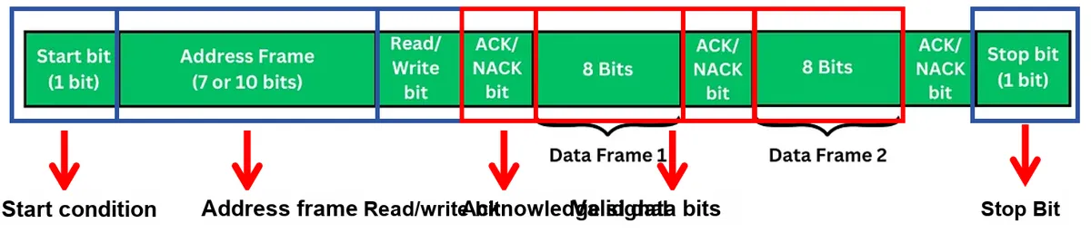
0. Data Validation
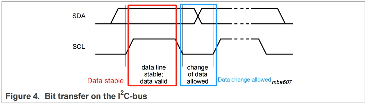
When data is transmitted via the I2C bus, one data bit is transferred during each clock pulse of SCL; while the clock signal SCL is at a high level, the data on the serial data line SDA must remain stable. Only when the signal on the clock line SCL is at a low level, the high or low level state on the data line SDA is allowed to change, and when SCL is at a high level, changes on the data line SDA are defined as control commands (start signal and stop signal).
1. Start Conditions / Stop Conditions
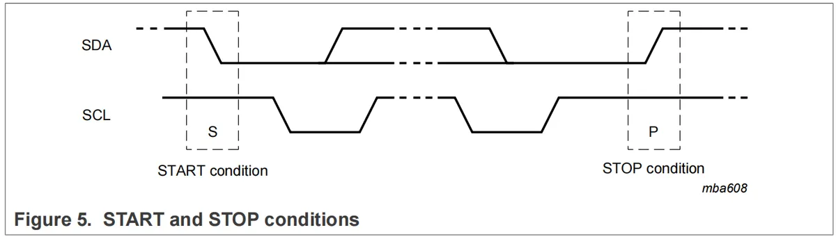
When the bus is in an idle state, both SCL and SDA remain at a high level.
Bus Idle State
Here, it should be noted that when the bus is in an idle state, both the SDA and SCL lines are definitely at a high level. However, when both the SDA and SCL lines are at a high level, the bus is not necessarily in an idle state; for example, when the bus is transmitting the data "1", both SDA and SCL are at a high level, but the bus is not in an idle state at this time. For the bus to be in an idle state, the duration for which the high level is maintained on both SCL and SDA shall be no less than tBUF (tBUF: ≥4.7us for standard mode, ≥1.3us for fast mode, ≥0.5us for fast-mode plus, ≥80ns for ultra-fast mode).
The start signal for I2C communication is initiated by the master device: when SCL remains at a high level, SDA transitions from a high level to a low level. After the start condition is generated, the bus is in a busy state and is exclusively occupied by the master and slave devices involved in this data transmission, making the bus inaccessible to other I2C devices.
Similarly, the stop signal for I2C communication is initiated by the master device: while SCL remains at a high level, SDA transitions from a low level to a high level. After the stop condition is generated, the master and slave devices involved in this data transmission will release the bus, which returns to an idle state once again.
2. Restart Signal
On the IIC bus, the master can transmit multiple bytes of data in one go; after sending the first data byte, it can send another Sr (repeated start signal) to continue occupying the bus. When SCL is at a high level, a high-to-low transition of SDA generates a repeated start signal, which is essentially a start signal.
3. Clock Stretching
Each byte placed on the SDA line must be 8 bits in length. The number of bytes that can be transmitted per transfer is not limited, but it should be noted that there must be an ACK acknowledge signal after each byte. Bytes are transmitted in big-endian order, with the MSB (Most Significant Bit) first and the LSB (Least Significant Bit) last.
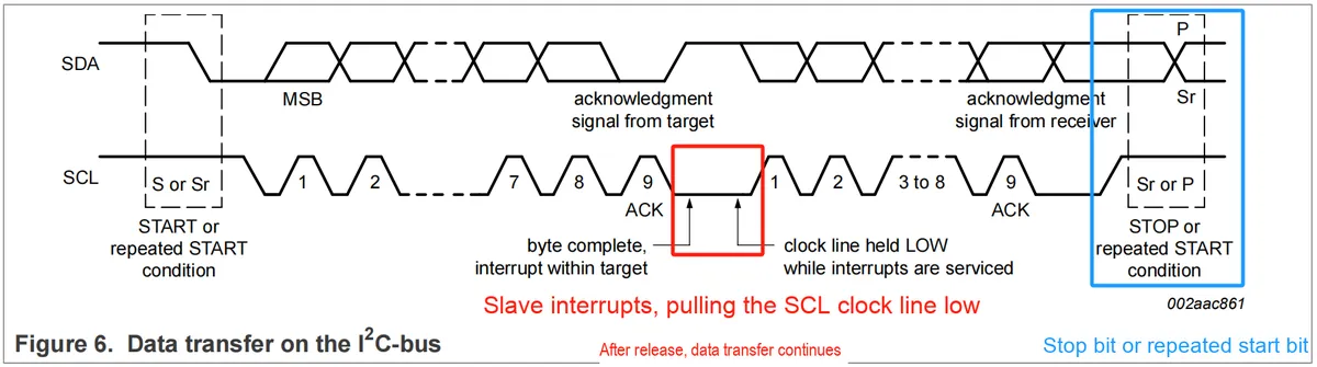
When transmitting a byte, the slave may be able to receive the data byte quickly, but require more time to store/process the received byte or prepare a byte for transmission. If the slave needs to delay the time to receive the next data, for example, after receiving one data, an I2C reception interrupt is generated, and the program jumps to the interrupt service routine for processing, which takes some time, the slave can pull the clock line SCL low and hold it at the low level to force the master to enter a waiting state.Once the interrupt service routine is completed, the slave can release the clock line to allow the master to continue transmitting subsequent data, thus providing the slave with sufficient time to transfer the data bytes it has received or to prepare the data bytes to be transmitted.
4. Slave Address Frame
After the start signal, the first byte consists of 7 or 10 address bits and 1 read/write (R/W) bit, and the address frame serves as the identifier for the slave device on the I2C bus, indicating which slave the master is initiating communication with.
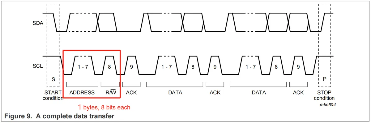
I2C supports both 7-bit addressing and 10-bit addressing:
- For 7-bit addresses: one byte is transmitted to set the 7-bit address, and the 7 address bits plus 1 read/write bit form a single byte that is transmitted over the SDA line.
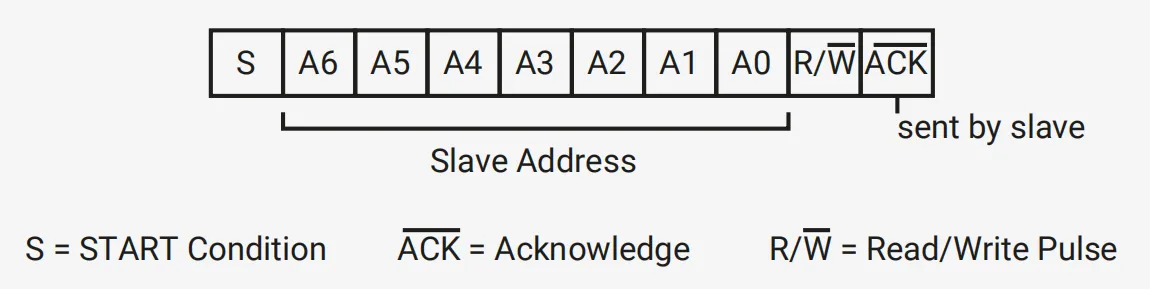
- For 10-bit address bits: two bytes are transmitted to set the 10-bit address. First, for the first byte, the frame header 11110 is frame interpolated before the 9th and 8th bits of the address frame to inform the slave that this is a 10-bit address transmission; the second byte corresponds to bits 7 to 0 of the address frame.

Whether using 7-bit address bits or 10-bit address bits, it is mandatory to wait for the receiver's acknowledgment after the transmission of each byte is completed.
Not all 7-bit address bits/10-bit address bits are available, and some address bits have special meanings and cannot be used:
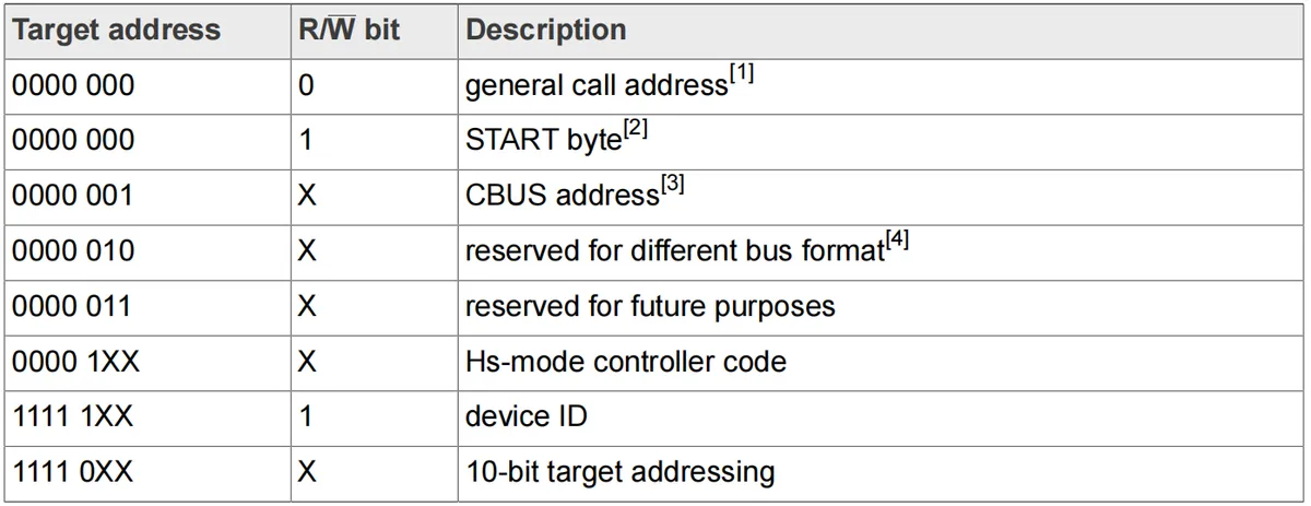
The allocation of these special addresses is determined by the chip design and manufacturer. Specifically, when all address bits are 0 and the transmission direction bit is also 0, it serves as the broadcast call address, which is used for multiple functions such as software reset and writing data to the slave's internal storage space. When the broadcast call address is used, all hosts connected to the I2C bus will be addressed.
5. Read-write bit
The read/write bit is used to indicate whether the host is sending data to the slave or requesting to receive data:
- 0 indicates that the host will start writing data to the slave from the next byte
- 1 indicates that the host will read data from the slave starting from the next byte
6. Acknowledgment Signal
Whenever the transmitter finishes transmitting one byte, the receiver must send an acknowledge (ACK) bit to confirm whether the receiver can successfully receive the data. After the transmitter completes the transmission of one byte of data (along with 8 SCL clock pulses), it releases the SDA line before the arrival of the 9th SCL clock pulse; the receiver then sends an acknowledge bit on SDA, that is, the slave pulls SDA low. Conversely, if SDA remains at a high level at this point, it indicates no acknowledgment, meaning the slave has not received the data from the master.
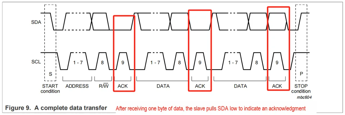
When a NACK (non-acknowledge signal) is received or transmitted, regardless of whether the host acts as a receiver or a transmitter, the host shall either send a stop condition to terminate the data transmission, or transmit a restart signal to proceed with the next data transmission.
7. Data bits
The amount of data that can be sent in each I2C transmission is not limited, but transmission always takes place in units of bytes, and a slave device's acknowledgment must be awaited after each byte is transmitted. In addition, I2C always uses big-endian order, meaning that the MSB (Most Significant Bit) comes first and the LSB (Least Significant Bit) comes last.
1.2.3.2.2 Introduction to Data Transmission Process
Here, taking the case of 7 address bits as an example, we will explain the specific processes of the master sending data to the slave and the slave sending data to the master.
1. The master device sends data to the slave device
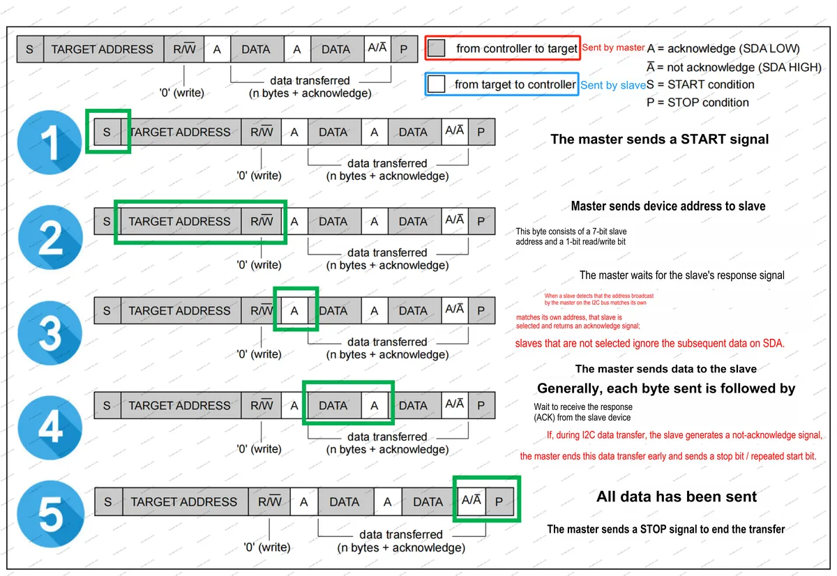
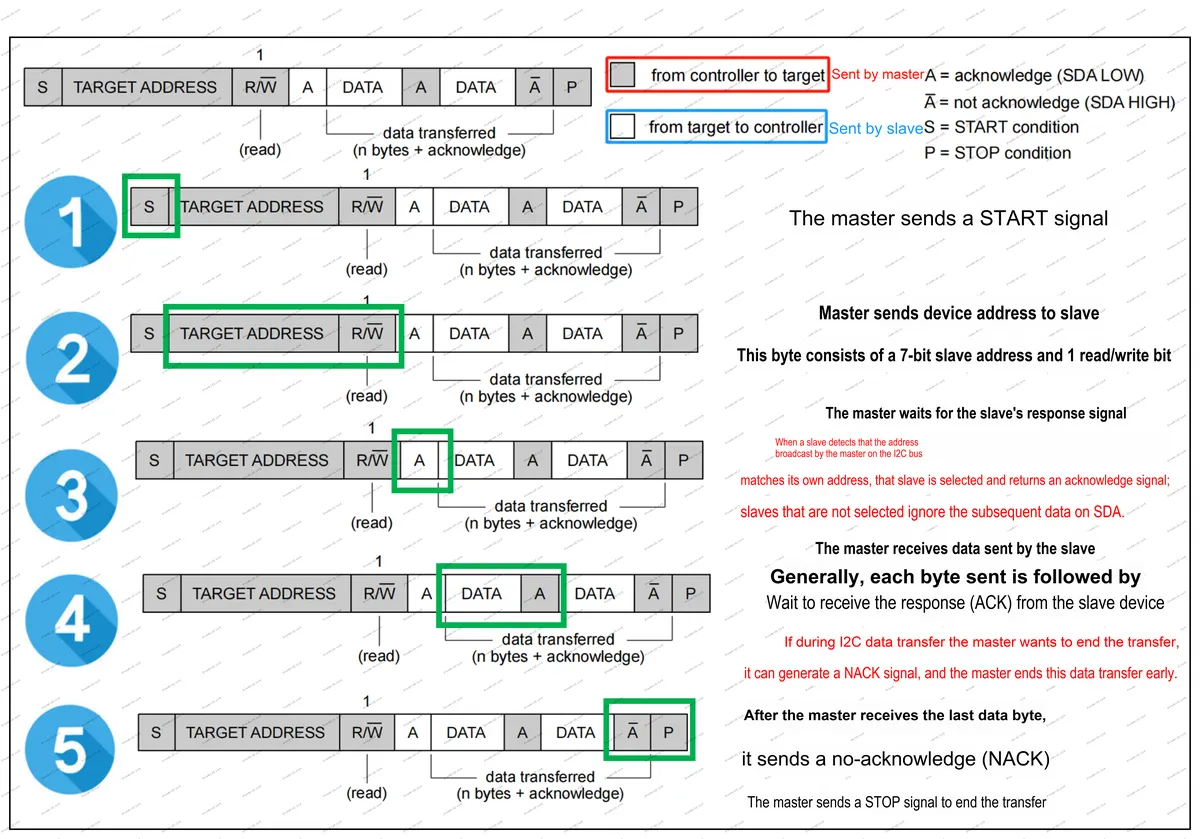
2. The master reads data from the slave
When the master device reads data from the slave device, it first needs to send a signal to the slave to inform the slave that "the master intends to read a certain type of data"(i. e., during the first communication, after the master has transmitted the address bits and the read/write control bits, the master sends an instruction recognizable to the slave, which indicates that the slave will send a specific type of data to the master in the subsequent communication); the process of the first communication follows the aforementioned steps. After that, a new communication session is initiated, in which the master receives the data transmitted by the slave, with the specific process detailed as follows:
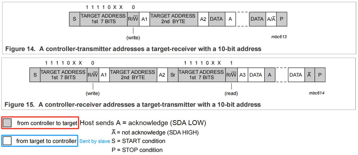
When the address bit is 10 bits, the process of the master sending and receiving data is similar to that with 7 address bits, except that the address is transmitted in two bytes:
1.2.3.2.3 Clock Synchronization
Consider a situation where two hosts are connected to the I2C bus. When the bus is idle, both hosts detect that the SDA line is high and can start data transmission. However, considering the situation we mentioned above, there is only one host on the bus that can control the bus for data transmission. At this time, clock synchronization and bus arbitration are needed to determine which host controls the bus.
Now, let's take a look at the process of clock synchronization. Clock synchronization is completed by the "line and" function between the host's SCL interface and the SCL bus. The so-called "line and" function means that when the SCL interface of one host is set to a low level, no matter what state the SCL interface of the other host is currently in, the SCL bus is presented as a low level (i.e. 0 & 0 = 0, 0 & 1 = 0, 1 & 1 = 1).
In the following figure, the process of clock synchronization between Host 1 and Host 2 is as follows:
- Host 1 first lowers its own SCL interface, and the entire SCL bus presents a low level
- When the SCL interface of host 2 detects the transition from high to low on the SCL bus, host 2 pulls down its own SCL interface
- Master 1 starts counting down the required SCL low-level hold time, and pulls its own SCL interface to a high level once the specified low-level duration elapses (here, the low-level hold time of Master 1 is short, assumed to be t1L); when pulling its own SCL interface low, Master 2 also starts counting down the required SCL low-level hold time, and pulls its own SCL interface to a high level once the specified low-level duration ends (here, the low-level hold time of Master 2 is long, assumed to be t2L).It can be seen that due to the "wired-AND" function, the SCL interface of Master 2 is in a low-level state, the SCL interface of Master 1 enters a high-level waiting state, and the bus remains in a low-level state.
- When both Master 1 and Master 2 transition from a low level to a high level, the SCL bus assumes a high level, and the two masters start counting down their respective required SCL high-level hold times until the specified high-level duration elapses (here, Master 2 has a longer high-level hold time, denoted as t2H, while Master 1 has a shorter high-level hold time, denoted as t1H). Master 1 completes the high-to-low level transition first and enters the waiting state for the next high level.
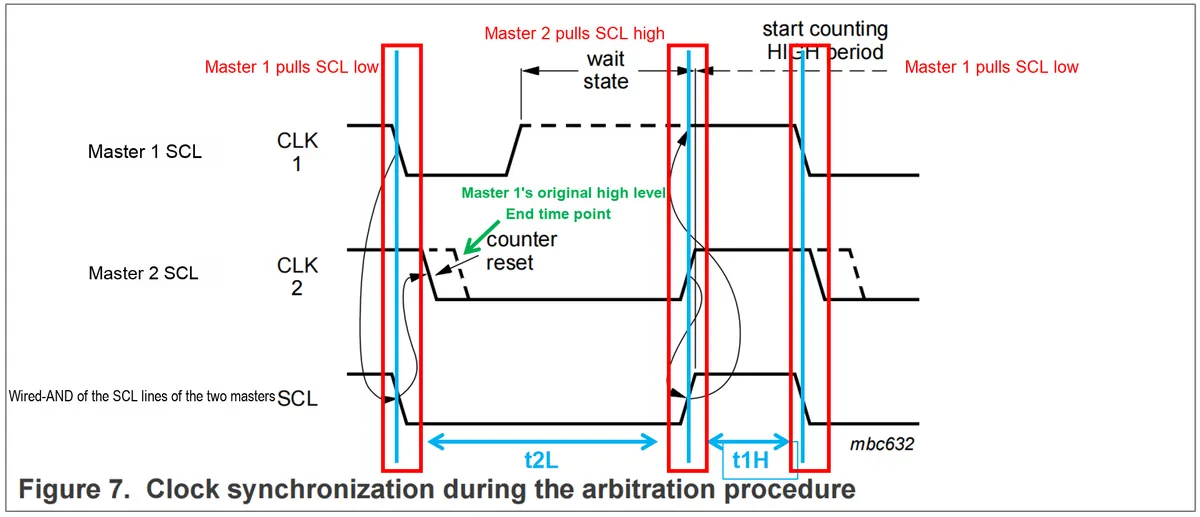
It can be seen that this generates a synchronized SCL bus clock signal, whose low-level hold time is determined by t2L (the low-level hold time of the master with the longest low-level hold time), and whose high-level hold time is determined by t1H (the high-level hold time of the master with the shortest high-level hold time).
1.2.3.2.4 Bus Arbitration
Bus arbitration is only used in multi-master systems and is completed through the coordination of the SDA and SCL lines:
- The SCL line is responsible for clock synchronization: When two hosts are in the idle state, they initiate startup simultaneously. Then each pulls the SCL bus low and releases it to high level according to its own timing requirements, and generates a synchronized clock signal following the procedure described in the previous section.
- The SDA line is responsible for data arbitration: Here, the arbitration of SDA is performed on a bit-by-bit basis. During the transmission of each data bit, when SCL is at a high level, after the SDA interface line of each host outputs a level each time, it will immediately read back the level of the SDA bus to determine whether its own output is consistent with the bus:
- If there is a match: the host wins the arbitration, gains control of the bus, and proceeds with data transmission.
- If there is a discrepancy: then this host has not won the arbitration, loses control over the bus, and the bus is handed over to the arbitration-winning host for data transmission
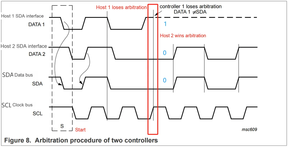
It should be noted that:
- During the arbitration process, the host that wins the arbitration will not lose any data
- A host that fails arbitration can continue generating clock pulses until the byte for which it lost arbitration ends, and may re-initiate arbitration when the bus is idle.
- The arbitration process cannot be completed by a single arbitrator, and multiple arbitrators may be required.
1.2.3.2.5 Broadcast Call Address
The broadcast call address (0000 0000) is used by the master to address each slave connected to the I2C bus simultaneously.
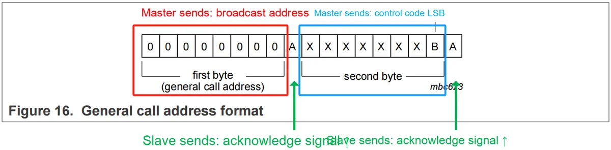
When a host transmits a broadcast call address, it is typically divided into two bytes:
- Broadcast address: The slave to be addressed will automatically send back an acknowledgment signal and then receive the control command byte;
- Control Command: A byte representing a specific control command, with the detailed description as follows:
- When the 8th bit of the second byte B is 0:
- 0000 0110 (06h): Slave hardware reset and write data to the internal storage space of the slave
- 0000 0100 (04h): Write data to the slave's internal storage space
- 0000 0000 (00h): This code is not permitted to be used as the second byte
Except for the three commands listed above, the official has not yet updated and added definitions for the remaining control commands, and the slave device must ignore them.
- When the 8th bit of the second byte B is 1:
The first seven bits represent the address of the master itself. After receiving the first byte and this byte sequence, all addressed slave devices will register the first seven bits of the second byte as the master's address. If this master also has slave functionality, it can switch to the slave role, with its slave address being the registered 7-bit address; the original slave will then become the master and send data to the original master (now acting as a slave).

For example, for a keyboard, since the keyboard scanner does not know exactly what the connected device is, it sends a combined sequence of the first byte "00000000" and the second byte "xxxxxxx1" as a host to initiate a hardware broadcast. The addressed slave device registers the 7-bit address of the keyboard, after which the roles are swapped: the keyboard becomes the slave, and the original slave becomes the host. The new host then uses the 7-bit address of the keyboard as the slave address to address the keyboard, thereby controlling the keyboard and acquiring key values from it. Naturally, these devices that undergo role switching must have both host and slave functions at the same time.
- When the 8th bit of the second byte B is 0:
1.2.3.2.6 Start byte transmission
A single-chip microcontroller can be connected to the I2C bus in two ways:
- Using hardware I2C peripheral: The microcontroller integrates an I2C bus hardware interface. Programmers operate it by configuring internal I2C registers to perform interrupt-based read/write operations or use it in conjunction with DMA, which delivers fast read/write speeds.
- GPIO Software Simulation of I2C: When a microcontroller does not have an integrated I2C bus hardware interface and simulates I2C timing via software emulation, it is necessary to continuously monitor the bus through polling, which leads to high CPU overhead and slow response speed.
When a slave device implemented via software-simulated I2C communicates with a master device using hardware I2C peripheral, a speed difference exists between the two. When the master device with hardware I2C peripheral initiates communication, it will send a start condition/start signal, which has an extremely short duration. At this point, to save CPU overhead, the device with software-simulated I2C will perform polling on the I2C bus at a low speed, which may cause it to miss the start condition, thus resulting in failure to establish communication between the two parties.
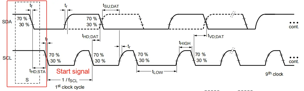
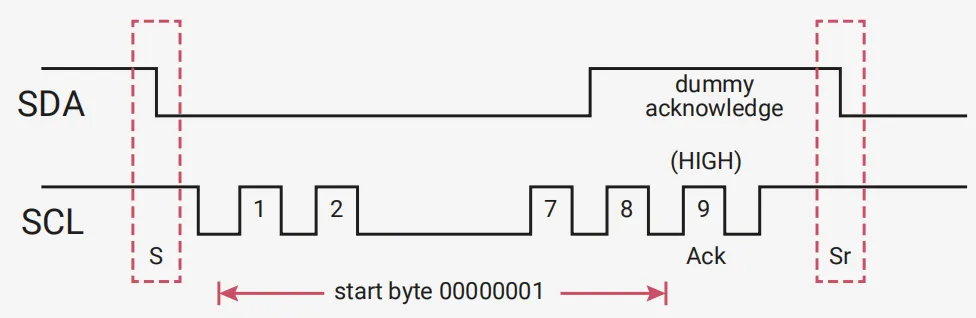
The solution to this problem is to use start byte transmission, which is a special handshake synchronization byte sequence specifically designed to accommodate slow polling of devices. Devices using hardware I2C peripherals send a start byte, which is a much longer start procedure than normal, including a start condition, a start byte (0000 0001), a no-acknowledge clock pulse (NACK) and a restart signal:
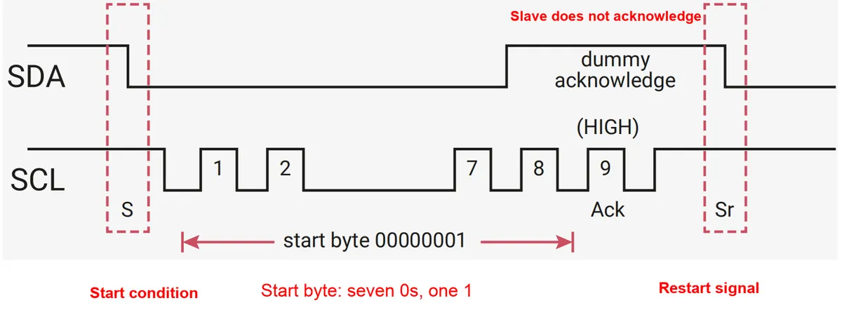
A slave device using software-emulated I2C will switch from a low sampling rate to the correct main sampling rate and start high-speed polling to respond to data from a master device using hardware I2C peripherals as soon as it detects one '0' among the seven '0' s in the start byte. Once the I2C transmission ends, the slave device using software-emulated I2C can resume polling at a slower rate after receiving all data and the stop signal. By using the start byte, the slave device using software-emulated I2C can sample at a lower rate when in the idle state to save CPU usage.
It should be noted that there is an acknowledge-related clock pulse after the start byte, but no device is allowed to send an ACK; this is only to comply with the byte processing format used on the bus, and the slave only needs to send a NACK.
1.2.3.2.7 Bus Clear
Bus clearing refers to eliminating the fault where the bus is stuck at a low level and restoring it to a normal state.
When the SCL bus remains at a low level for an extended period, the bus can be cleared via the following methods:
- Reset I2C peripheral hardware
- Restart the power supply
When the SDA bus remains at a low logic level for an extended period, the bus can be cleared via the following methods:
- The master device sends 9 clock pulses
- Reset I2C peripheral hardware
- Restart the power supply
1.2.3.2.8 Device ID
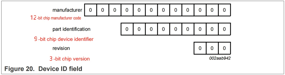
Before shipment, chip manufacturers store the device ID (identification code) in the read-only memory space inside the chip, with address bits from 7C (111 1100) to 7F (111 1111) reserved for the device ID. The device ID contains the following content: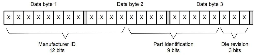
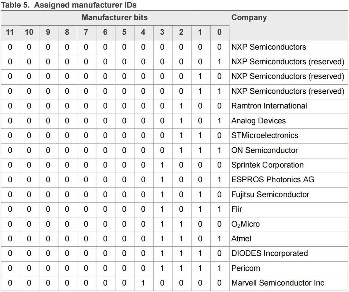
- 12-bit chip manufacturer name code: Each manufacturer has a unique code (e. g., "0000 0000 0000" stands for NXP).
Common chip manufacturers are coded as follows:
- 9-bit Chip Device Identifier: Assigned by the chip manufacturer (e. g. AT24C02).
- 3-digit chip version: Specified by the manufacturer (e. g. RevX)
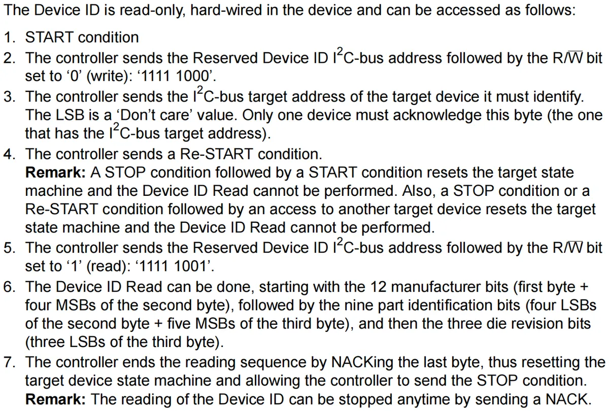
The device ID is read-only and can be accessed in the following ways:
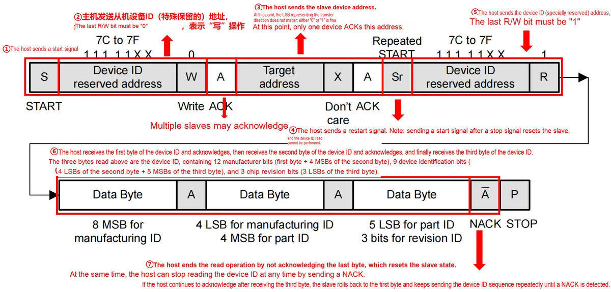
1.2.4 Advantages of the IIC Bus
1.2.4.1 Comparison with UART Serial Communication
For UART serial communication, it has the following disadvantages compared with IIC: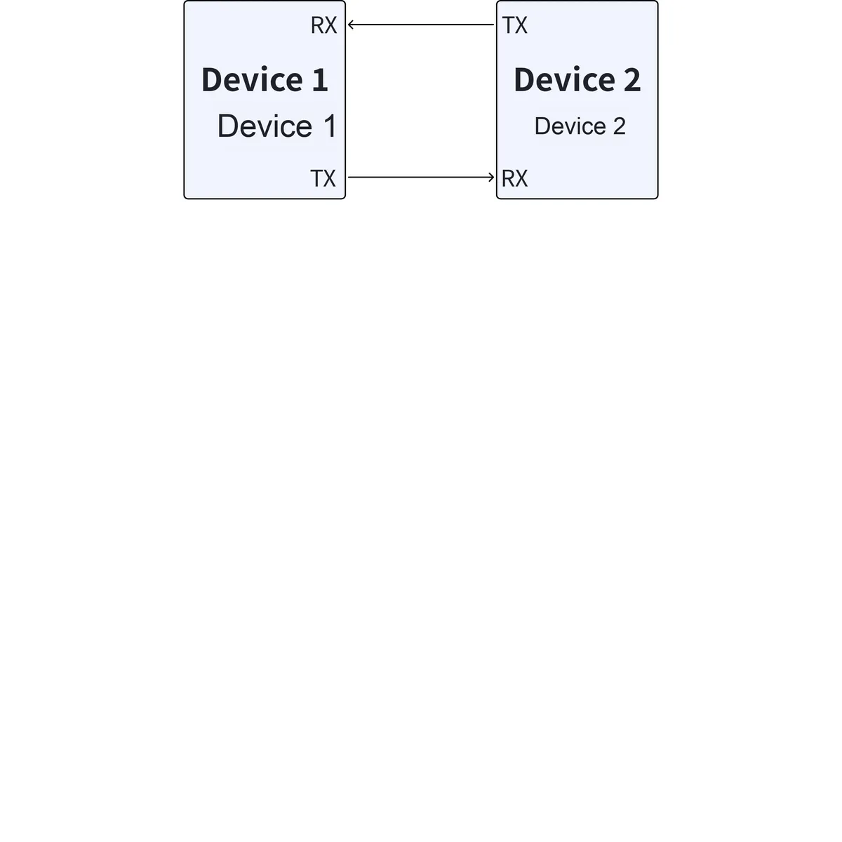
- Since serial ports operate on asynchronous communication without a synchronous clock line, devices using serial ports must be configured with the same data rate in advance. In addition, the clock rates of the receiving end and transmitting end of a serial port need to be approximately consistent, otherwise data garbling may occur. Meanwhile, when transmitting a piece of 8-bit data, there are at least two synchronization bits (i. e., one start bit and one stop bit), which means that transmitting every 8 valid data bits requires the transmission time of 10 bits, resulting in low transmission efficiency.
- The core drawback of UART is that it is only suitable for communication between two devices. Although multiple devices can be connected to a single serial port through external circuit design, the problem of bus contention will inevitably arise.
- In addition, the UART communication rate is relatively low, and the UART peripherals of most chips only support a maximum rate of 230400 bits/s.
Simply put, serial communication is suitable for scenarios where only two devices are transmitting data.
1.2.4.2 Comparison of SPI Serial Peripheral Interface
For the SPI (Serial Peripheral Interface), it has the following shortcomings compared with IIC: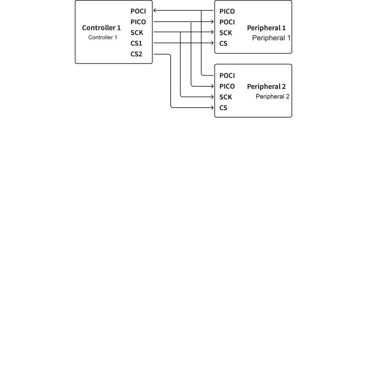
- The most obvious drawback of SPI is the number of pins required. Connecting a microcontroller to a single external device via SPI needs a minimum of four wires, and each additional peripheral device requires an extra chip-select I/O pin on the controller. The large number of connections for each device makes it difficult to route signal lines in a compact PCB layout.
- SPI allows only one master on the bus, but it supports any number of peripherals, limited only by the driving capability of the devices connected to the bus and the number of available chip select pins.
Simply put, SPI is well suited for use in full-duplex communication with high data rates.
1.2.4.3 Advantages and Disadvantages of the IIC Bus
The IIC protocol has the following advantages:
- Adopting the hardware setting mode of device address, it avoids the device chip select line addressing like SPI through software addressing, significantly simplifies the connection between the MCU and peripheral devices, and meanwhile uses a 7-bit or 10-bit addressing scheme, allowing a large number of devices to be connected to the same bus
- Any device that complies with the IIC standard can be connected to the bus regardless of its process or voltage level standard, which facilitates the construction of complex networks.
- I2C communication requires the addressed device to return an acknowledgment message, making the communication relatively reliable. Meanwhile, the I2C protocol incorporates a clock synchronization mechanism between devices on the bus, which helps maintain correct timing and ensure accurate data sampling.
- Multiple hosts are allowed to exist. Any device capable of transmitting and receiving data can act as the bus master. A bus master can control signal transmission and clock frequency, and there can only be one bus master at any point in time.
The IIC protocol has the following drawbacks:
- I2C is not well-suited for long-distance communication. Bus capacitance and resistance limit the bus length, and additional measures may be required to achieve longer-distance communication. Meanwhile, the number of peripheral devices connected to IIC is not unlimited, and there is a limit to the number of extended devices on the bus. The number of extended devices on the bus is not determined by current load, but by capacitive load. The interface of each device on the IIC bus has a certain equivalent capacitance; the more devices there are (extended peripheral devices can be regarded as being connected in parallel to the bus of the main device), the larger the capacitance value, which will cause signal transmission delay.
- Compared with some other Communication Protocols such as SPI (Serial Peripheral Interface), I2C may have a relatively low data transmission rate, and the maximum transmission rate of high-speed IIC lines can reach 400kb/s
- I2C does not have a built-in error checking mechanism. Although it does include acknowledge bits, we have to implement more complex error detection and correction functions at higher protocol layers.
- It is susceptible to interference and does not check for communication errors. When this communication method is used in harsh environments (such as industrial control settings surrounded by high-power equipment) or when the communication line is relatively long (around 10 meters), the transmission rate will slow down significantly.
1.3 Structure and Concepts of I2C Peripherals
1.3.1 Basic Structure of I2C Peripherals
The I2C peripheral of the Raspberry Pi Pico is configured based on the synchronous system DW_apb_i2c IP core, which is a common I2C bus IP core typically applied in embedded systems.
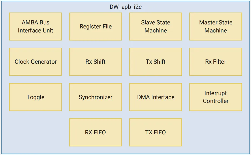
The DW_apb_i2c I2C bus IP core comprises the following components:
- AMBA Bus Interface Unit: APB interface module, which receives 32-bit APB interface signals and converts them into general-purpose interface signals
- Register File: A register module that also serves as a software access interface
- Slave finite-state machine: Slave finite-state machine, which implements slave functions, monitors the bus address, performs address matching and data processing in accordance with the slave protocol.
- Master finite-state machine: A master finite-state machine that implements the master function and generates I2C protocol timings.
- Clock Generator: A clock generation module that generates clock signals, start and stop signals in accordance with timing requirements, performs idle state checking, and ensures data setup and hold; the clock for I2C peripherals is generated by inputting the system clock clk_sys into this clock generation module.
- Rx Shift: RX shift register, which receives serial data from the SDA line and converts it into parallel data stored in the RX_FIFO
- Tx Shift: A TX shift register that processes the parallel data from TX_FIFO and outputs it serially bit by bit to the SDA line of I2C.
- Rx Filter: RX filter, which detects events on the bus such as start events and stop events
- Toggle: Generates a pulse and flips the state, which is used for signal transmission across clock domains
- Synchronizer: Synchronous clock signal
- DMA Interface: DMA interaction interface
- Interrupt Controller: Interrupt controller, which generates and stores interrupt signals
- RX FIFO: Stores the data received by the RX shift register
- TX FIFO: Receive and store the data transmitted by the CPU from the APB bus
1.3.2 Registers Related to I2C Peripherals
The base addresses of the I2C0 and I2C1 registers are 0x40044000 and 0x40048000 respectively, which are defined as I2C0_BASE and I2C1_BASE in the SDK.
The registers for controlling I2C peripherals are shown in the following figure:
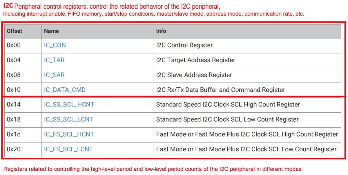
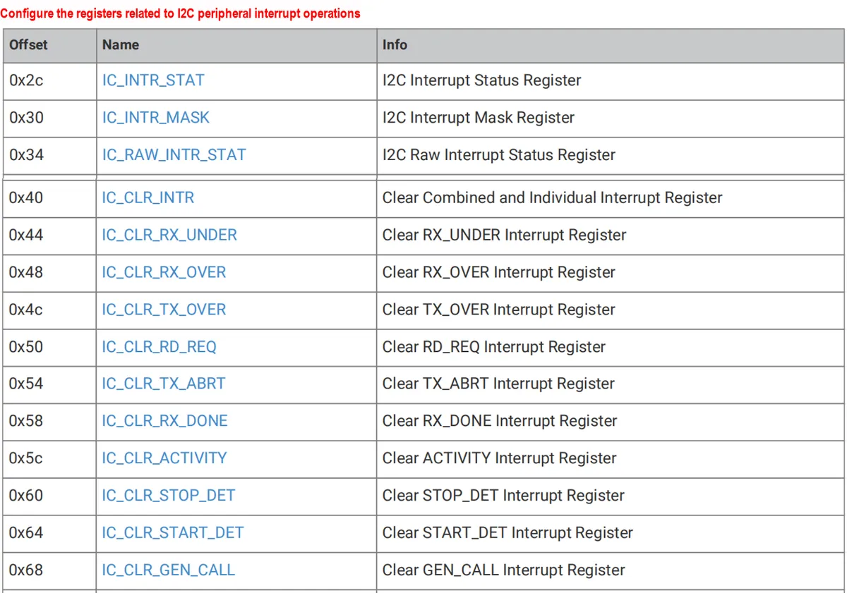
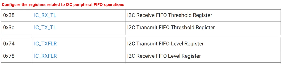
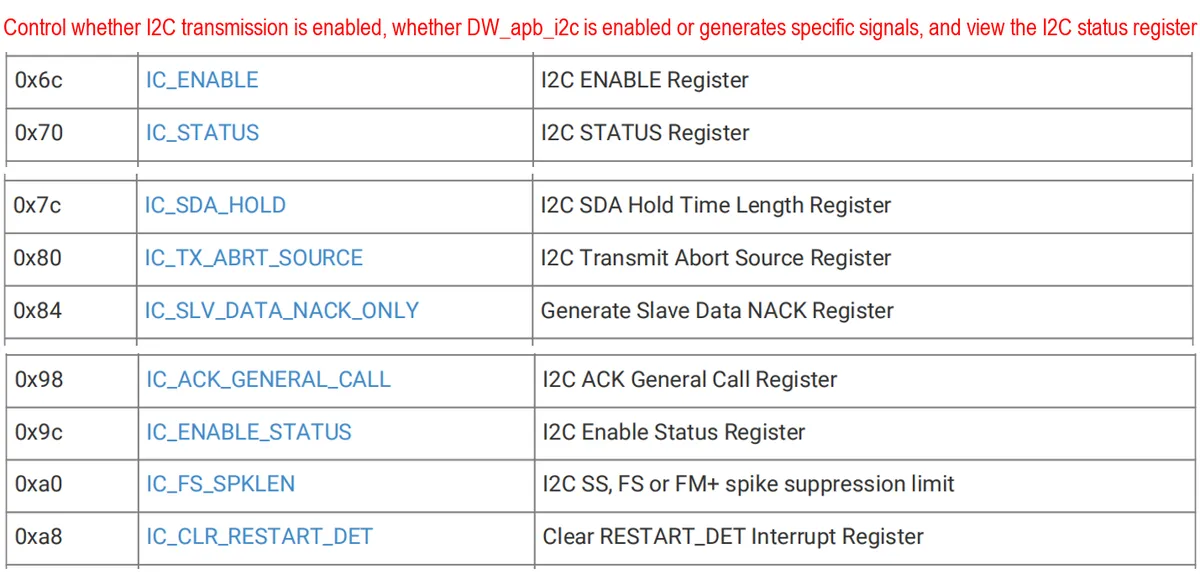

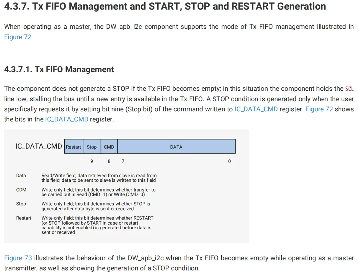
Regarding how to configure these registers during I2C peripheral transmission, since this tutorial uses MicroPython for development, there is basically no need to touch these low-layer related contents, so it will not be described further. Interested readers can refer to Section 4.3 about the I2C peripheral in the RP2040 datasheet:
1.4 Overview of I2C on Raspberry Pi Pico
The Raspberry Pi Pico has two I2C peripherals with identical parameters: I2C0 and I2C1, and the optional SCL and SDA pins are shown in the blue area in the following figure:
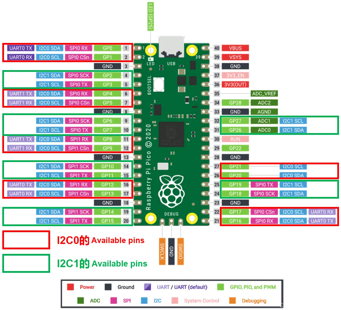
The following table shows all pins available for I2C communication:
I2C peripheral | SDA Pin | SCL pin |
I2C0 | GPIO0, GPIO4, GPIO8, GPIO12, GPIO16, GPIO20 | GPIO1, GPIO5, GPIO9, GPIO13, GPIO17, GPIO21 |
I2C1 | GPIO2, GPIO6, GPIO10, GPIO14, GPIO18, GPIO26 | GPIO3, GPIO7, GPIO11, GPIO15, GPIO19, GPIO27 |
Each I2C peripheral supports the following functions:
- Host mode/Slave mode (Host mode by default), with the default slave address being 0x055
- Supports 3 rate modes:
- Standard mode (0 to 100 Kb/s)
- Fast mode (≤ 400 Kb/s)
- Fast mode plus Enhanced Mode (≤ 1000 Kb/s)
- Supports 7-bit or 10-bit address modes;
- Supports DMA operations and interrupts
- Independent 16-byte receiving FIFO buffer and transmitting FIFO buffer
When using the I2C peripheral, the GPIO pins should be configured as follows:
- Enable the pull-up resistor (note that external pull-up is also required for the circuit, as the pull-up capability of the RP2040 pad cells is not sufficiently strong)
- Enable Schmitt trigger
- slew rate limiting
2. Software Control Method
We can use the machine.I2C class to control the I2C hardware peripheral for data transmission with external devices, or use the machine.SoftI2C class to generate a software-simulated I2C for data transmission with external devices. The differences between software I2C and hardware I2C are as follows:
I2C type | Principle | Operating Speed | Portability |
hardware I2C | Control the I2C peripherals of the Raspberry Pi Pico to implement communication functions | Fast | not high, the SDA interface and SCL interface of I2C peripherals require specific pins |
Software I2C | Communication function is implemented by simulating I2C timing through GPIO control | Slow | High, any pin can be used as the SDA interface and SCL interface of I2C |
2.1 Constructor of the machine.I2C class
The constructor of the machine.I2C class is as follows:
class machine.I2C(id, *, scl, sda, freq=400000, timeout=50000)
Construct an I2C object with the given parameters
The parameters are defined as follows:
- id - Identifies a specific I2C peripheral; can be set to 0 or 1 on the Raspberry Pi Pico
- scl - This should be a Pin object, specifying the pin assigned for SCL
- sda - This should be a Pin pin object, specifying the pin used for SDA
- freq - This should be an integer that sets the maximum frequency of SCL
- timeout - Timeout period, which refers to the maximum time allowed for I2C communication processing (in microseconds)
2.2 machine. Constructor of the SoftI2C class
The constructor of the machine.SoftI2C class is as follows:
class machine.SoftI2C(scl, sda, *, freq=400000, timeout=50000)
Construct a software-emulated I2C object with the given parameters
The parameters are defined as follows:
- scl - This should be a Pin object, specifying the pin assigned for SCL
- sda - Should be a Pin pin object, specifying the pin used for SDA
- freq - This should be an integer that sets the maximum frequency of SCL
- timeout - specifies the maximum duration to extend the waiting clock (i. e. the maximum time that the other communication device holds the SCL bus low), measured in microseconds; a timeout will trigger an OSError (ETIMEDOUT) exception.
2.3 Other Methods of the I2C Class
The machine.I2C class and machine.SoftI2C class can use the following methods to implement I2C communication.
2.3.1 General Method
Method | Description |
I2C.init(scl, sda, *, freq=400000) | Initialize the I2C bus with the given parameters:
It should be noted that for instances created using the hardware I2C class, due to the limitations of the hardware I2C peripheral, the actual clock frequency may be lower than the frequency we set through the initialization method or constructor. We can print an I2C instance to check the actual operating frequency of the I2C. |
I2C.deinit() | Disable the I2C bus; this method is not applicable to the Raspberry Pi Pico. |
I2C.scan() | Scan all slaves mounted on the I2C bus (the scanned slave addresses range from 0x08 to 0x77) and return a list of responsive devices. When the Raspberry Pi Pico, acting as the host, sends its address (including the write bit) on the bus and then pulls the SDA line low, the slave device will respond accordingly. |
2.3.2 Native methods specific to the machine.SoftI2C class
The following methods are used to implement primitive operations for I2C peripherals (such as sending a start bit, stop bit, reading data, and writing data), and are only available in instances of the machine.SoftI2C class.
Method | Description |
I2C.start() | Generate a START condition on the bus (SDA transitions to low while SCL is high). |
I2C.stop() | Generate a STOP condition on the bus (SDA transitions to high while SCL is high). |
I2C.write(buf) | Writes bytes from buf to the bus. Checks whether an ACK acknowledge signal is received after each byte; if a NACK non-acknowledge signal is received, stops transmitting the remaining bytes. This function returns the number of received ACK acknowledge signals. |
I2C.readinto(buf, nack=True, /) | Read bytes from the bus and store them into the pre-declared buf; the number of bytes to be read is the length of buf. After all bytes except the last one are received, an ACK acknowledge signal will be sent on the bus. After the last byte is received
|
2.3.3 Standard Method of I2C Bus
The following method implements the standard approach for the master device to read data from and write data to the slave device.
Method | Description |
I2C.readfrom (addr, nbytes, stop=True, /) | Read n bytes from the slave; the parameters are defined as follows:
|
I2C.readfrom_into (addr, buf, stop=True, /) | After reading len (buf) bytes from the slave, write the data into buf. The parameters are defined as follows:
|
I2C.writeto (addr, buf, stop=True, /) | Writes len (buf) bytes to the slave, with the content being the bytes contained in buf; the parameters are defined as follows:
|
I2C.writevto (addr, vector, stop=True, /) | Writes the bytes of each object in the vector to the slave; the parameters are defined as follows:
If a NACK (non-acknowledge signal) sent by the slave is received while writing the objects contained in the vector to the slave, the transmission of the next byte shall be stopped. This method returns the number of ACK acknowledgment signals sent by the slave device that have been received. |
2.3.4 Memory Read/Write Method of I2C Bus
When read-write storage devices such as external EEPROM (e. g. AT24C02) and external Flash act as slaves mounted on the I2C bus, we usually need to access the address of the slave device and the address of the corresponding register on the slave, and the following methods can be used in this case.
Method | Description |
I2C.readfrom_mem (addr, memaddr, nbytes, *, addrsize=8) | Read n bytes from the slave memory. The meanings of the parameters are as follows:
|
I2C.readfrom_mem_into (addr, memaddr, buf, *, addrsize=8) | Read n bytes from the slave memory and write them into buf; the parameters are defined as follows:
|
I2C.writeto_mem (addr, memaddr, buf, *, addrsize=8) | Write n bytes to the slave memory; the parameters are defined as follows:
|
For the machine.I2C class in MicroPython, the I2C peripheral cannot be used as a slave by default, and we also rarely use an MCU microcontroller as a slave in I2C communication, but this does not mean that we cannot implement the Raspberry Pi Pico as a slave using MicroPython. In fact, we can directly manipulate the underlying registers through MicroPython to use the Raspberry Pi Pico as a slave in the I2C Communication Protocol.
Here we refer to the code related to the Raspberry Pi Pico acting as an I2C Communication Protocol slave in aajshaw's Git repository, the link is as follows:
https://github.com/aajshaw/Raspberry-Pico-I2C-Slave
3. Application Examples
3.1 Controlling OLED Screen Display via I2C
3.1.1 Introduction to OLED Screens
The following are common OLED display modules, which can be used to display graphics and text information. After we burn the program into the microcontroller, we can display the values of variables we are interested in (such as sensor data), the change curves of data, or debug information on the OLED screen to indicate the running status of the program.
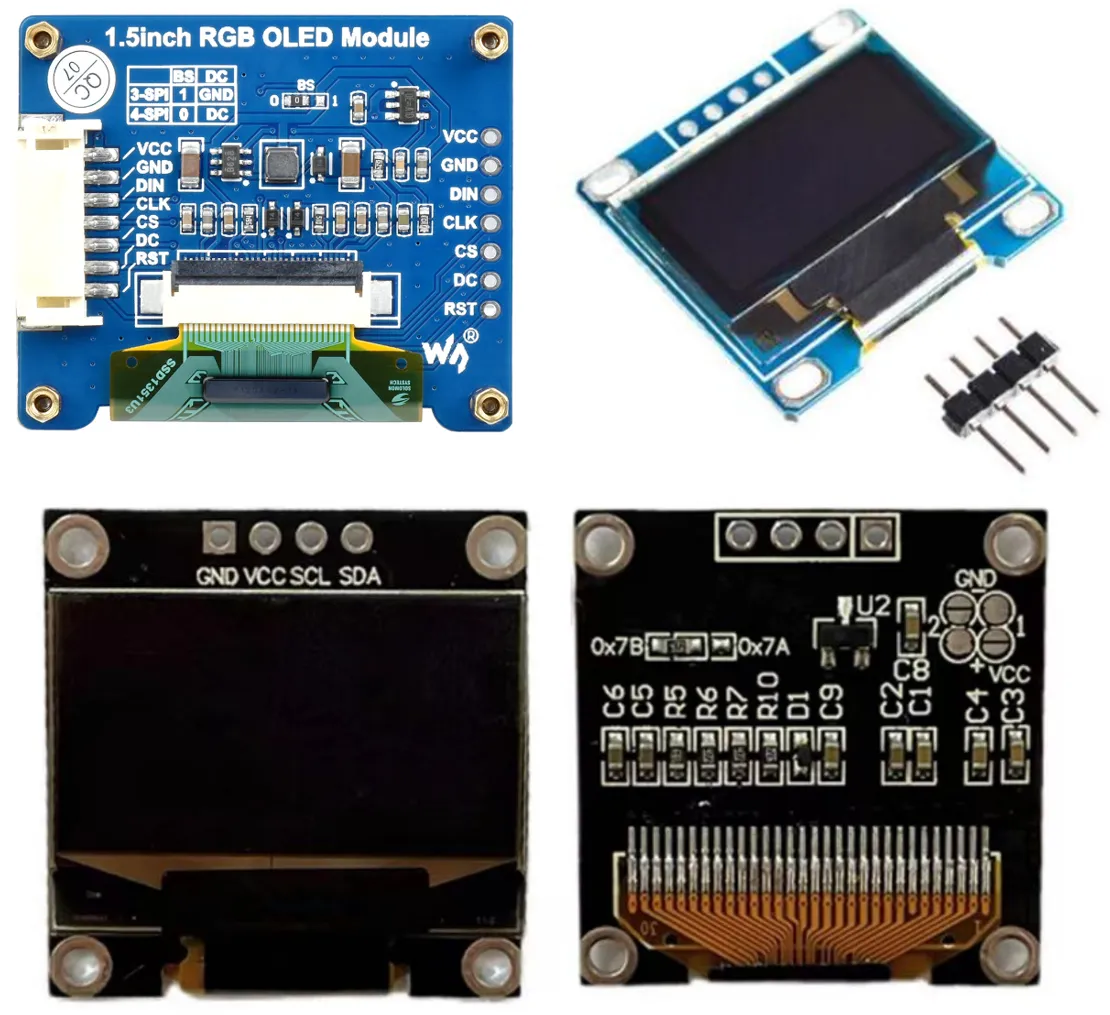
OLED, short for Organic Light-Emitting Diode, as the name suggests, refers to a light-emitting diode composed of organic semiconductors. When it comes to OLED, we have to mention the "three firsts" in the discovery and application of OLED technology:
- Organic semiconductors were discovered by Alan Heeger, Alan MacDiarmid and Hideki Shirakawa in the mid-1970s, a body of work that was awarded the 2000 Nobel Prize in Chemistry.

- The first OLED device was invented in 1987 by Ching Tang and Steven VanSlyke, who were working at the Eastman Kodak Research Laboratories at the time.

- The first company to use OLED display technology in a commercial product was Pioneer, which adopted a green monochrome flat-panel display with 256 x 64 pixels for its in-vehicle FM TV.

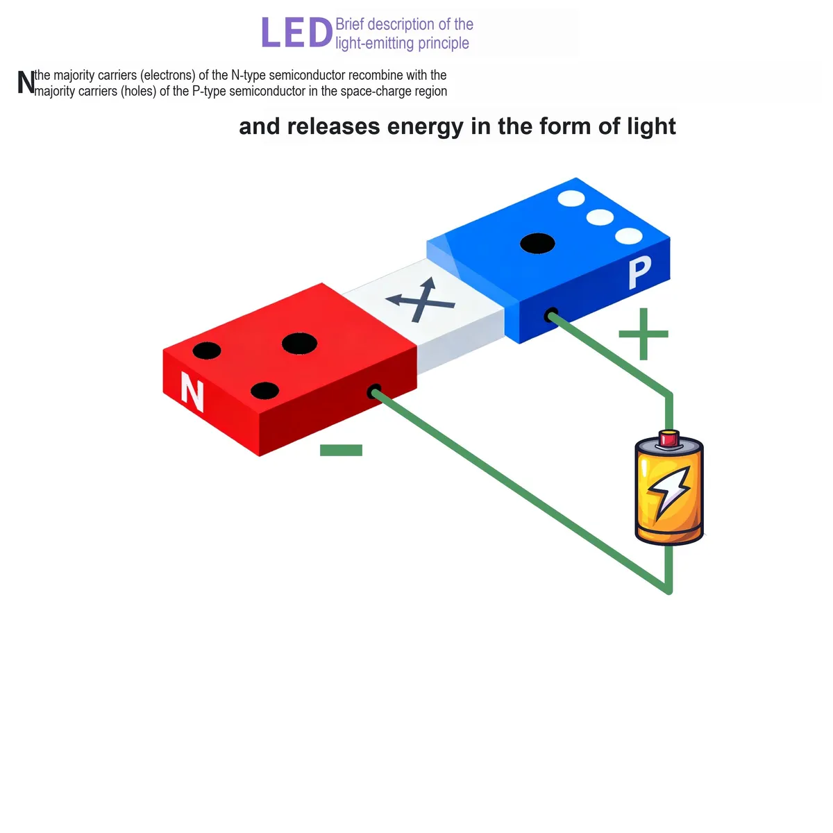
Before we explain the light-emitting principle of OLED, let's first review the working principle of LED that we learned in analog electronic circuits. LED stands for Light-Emitting Diode, which consists of one half of P-type semiconductor and one half of N-type semiconductor. At the junction of the two, electrons and holes recombine and release energy in the form of light, as illustrated in the diagram below:
OLEDs operate in a similar manner to LEDs, but use organic molecules to generate electrons and holes. A basic OLED consists of six distinct layers, with multiple protective glass or plastic layers at the top and bottom. The top layer is referred to as the seal, while the bottom layer is called the substrate. Between these layers lie a cathode (negative terminal) and an anode (positive terminal). Finally, between the anode and cathode are two layers made of organic molecules, known as the emissive layer and the conductive layer respectively:
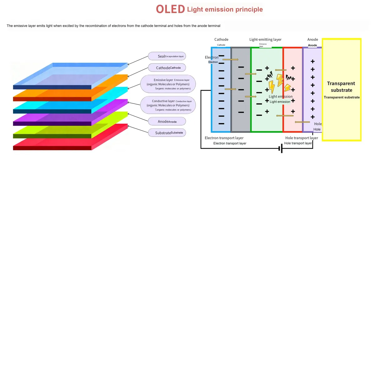
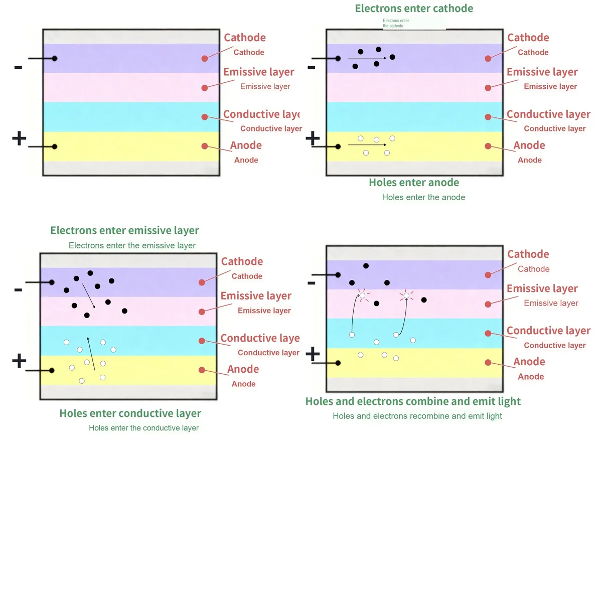
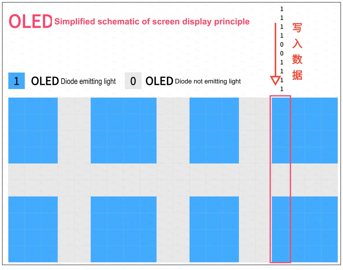
An OLED display is composed of multiple OLED diodes. Each OLED diode can be regarded as a pixel on the display, and we can use a microcontroller to control whether it emits light or not, so as to realize the function of displaying images and texts:
Compared with traditional LCD displays, OLED displays are thinner and lighter, require no backlight, consume less power, and feature a higher refresh rate. However, a widely cited issue is that OLED displays have a short service life. OLED displays are now extremely common and can be found in consumer electronics products such as smartphones, tablets, televisions, and smartwatches.
3.1.2 Introduction to the SSD 1306 Chip
SSD1306 is a single-chip CMOS OLED/PLED driver with controller for OLED dot-matrix graphic display system. It consists of 128 SEG (column outputs) and 64 COM (row outputs). It integrates a contrast controller, display RAM (GDDRAM) and an oscillator, thereby reducing the number of external components and power consumption. This chip features 256-level brightness control. Data or commands can be received via the following communication methods:
- 8-bit 6800/8080 Serial-Parallel Interface
- 3-wire/4-wire Serial Peripheral Interface
- I2C interface
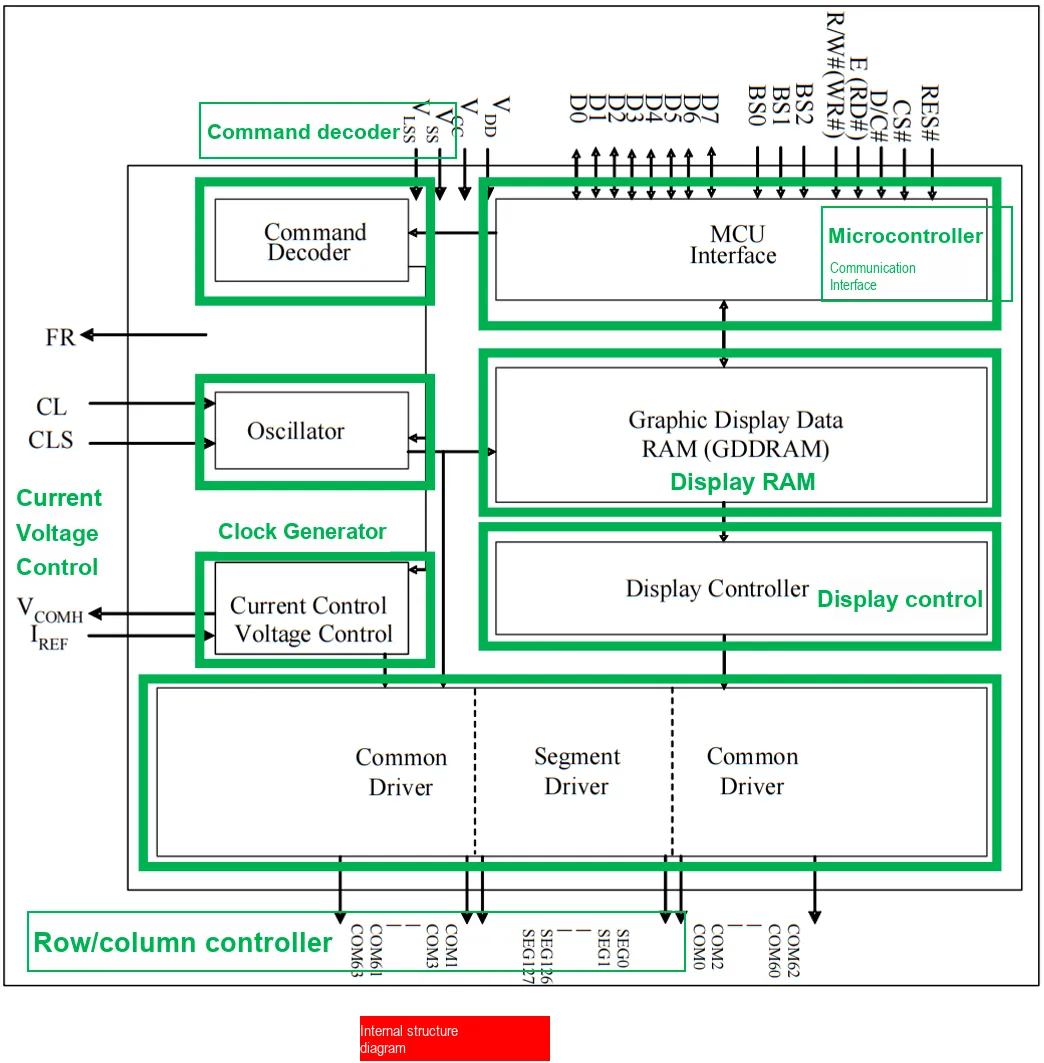
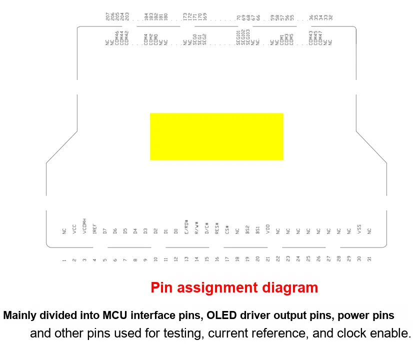
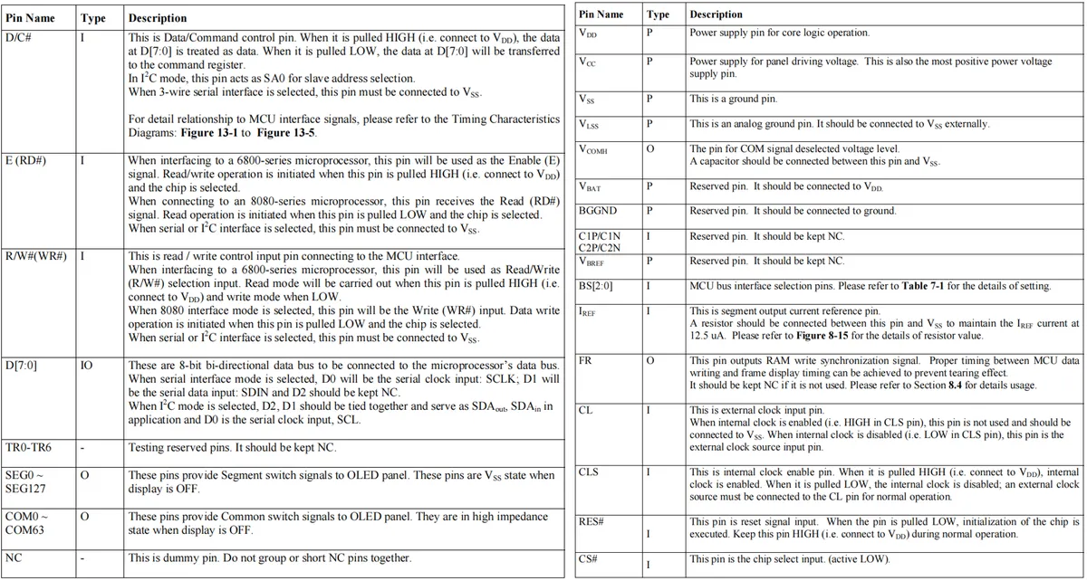
The operating voltage of the SSD1306 chip ranges from 1.65V to 3.3V, while the OLED display requires a supply voltage of 7V to 15V. We only need to provide a 5V voltage input to the entire module, and the built-in charge pump circuit of the SSD1306 will convert the voltage to meet the power supply requirements of both the SSD1306 chip and the display screen.
Simply put, the basic principle of controlling the display of an OLED screen via the SSD1306 chip is as follows:
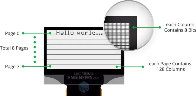
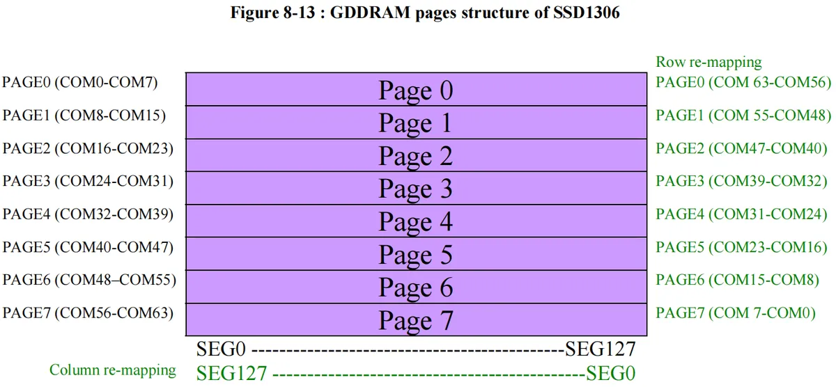
The SSD1306 uses its internal 1KB Graphic Display Data RAM (GDDRAM) to store the bit data of the image to be displayed on the entire OLED screen. This 1KB memory area is divided into 8 pages (PAGE0 to PAGE7), with every 8 rows of pixels (8*PIXEL) defined as one page. Each page contains 128 column SEGs, and each column can store 8 bits, i. e., one byte of data. By writing data to the 8 pixels of a column SEG, we can control the display effect of this column; by the same token, we can control the display effect of the entire screen.
To display the entire screen, we need to write 1024 bytes:
8 pages x 128 segments x 8 bits of data = 8192 bits = 1024 bytes = 1KB memory
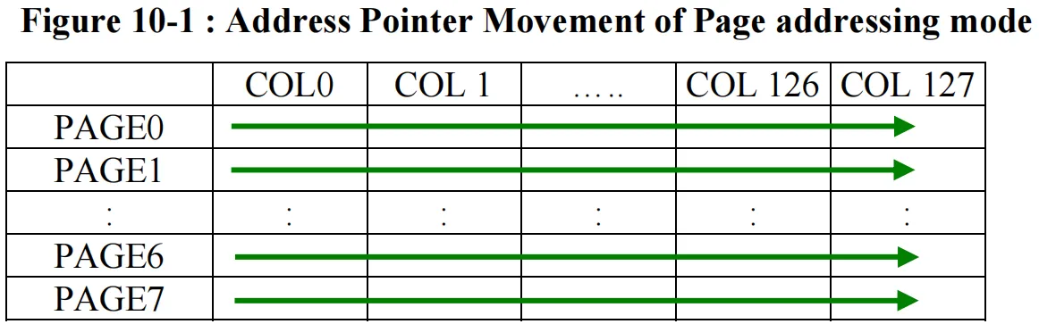
In page addressing mode, addressing is performed only within a single page (PAGEn), and the address pointer will not jump to other pages. After writing 1 byte of display data to GDDRAM each time, the column pointer is automatically incremented by 1. When all 128 columns have been addressed, the column pointer will point back to SEG0 while the page pointer remains unchanged. The user must set a new page and column address to access the RAM content of the next page. The page addressing mode allows users to conveniently modify data within a small area.
In page addressing mode, addressing is performed only within a single page. After writing 1 byte of display data to the GDDM each time, the column pointer is automatically incremented by 1. When all 128 columns have been addressed, the column pointer will return to the starting column position, namely SEG0, while the page pointer remains unchanged. The user must set a new page and column address to access the RAM content of the next page. The following figure is a schematic diagram of the column pointer movement sequence in page addressing mode:
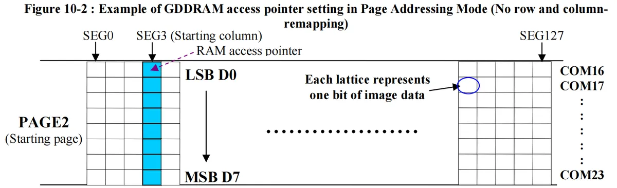
When we use the page addressing mode, when operating on a column of data within one page, we can only operate in bytes, that is, write 8 bits of data at a time. The data bit D0 is written to the top row, and the data bit D7 is written to the bottom row (from top to bottom, corresponding to from the lowest bit to the highest bit):
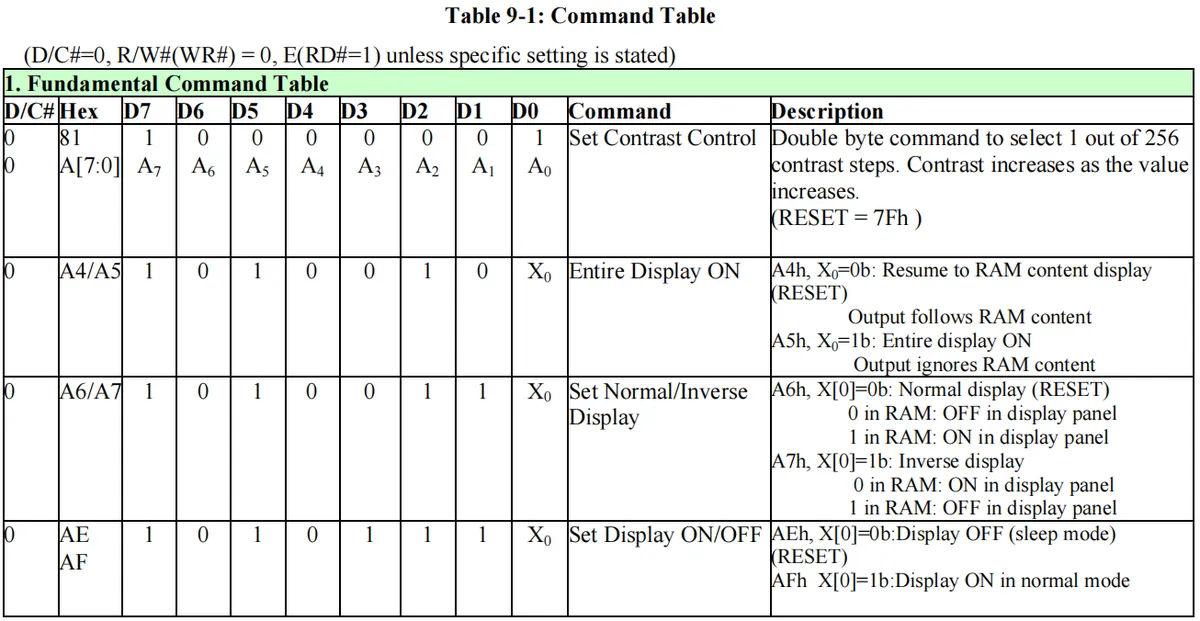
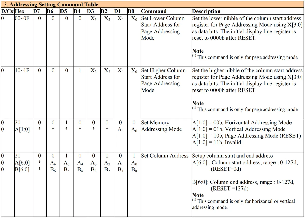
We can control the display effect of the OLED screen by writing commands and data to the SSD1306 via the I2C peripheral of the Raspberry Pi Pico. The control commands of the SSD1306 mainly consist of the following parts:
- Basic Instructions: Instructions for setting contrast, full-screen full brightness, normal/inverted display, and display on/off, etc.
- Address Instruction: Instructions related to setting the addressing mode and the parameters required for different addressing modes
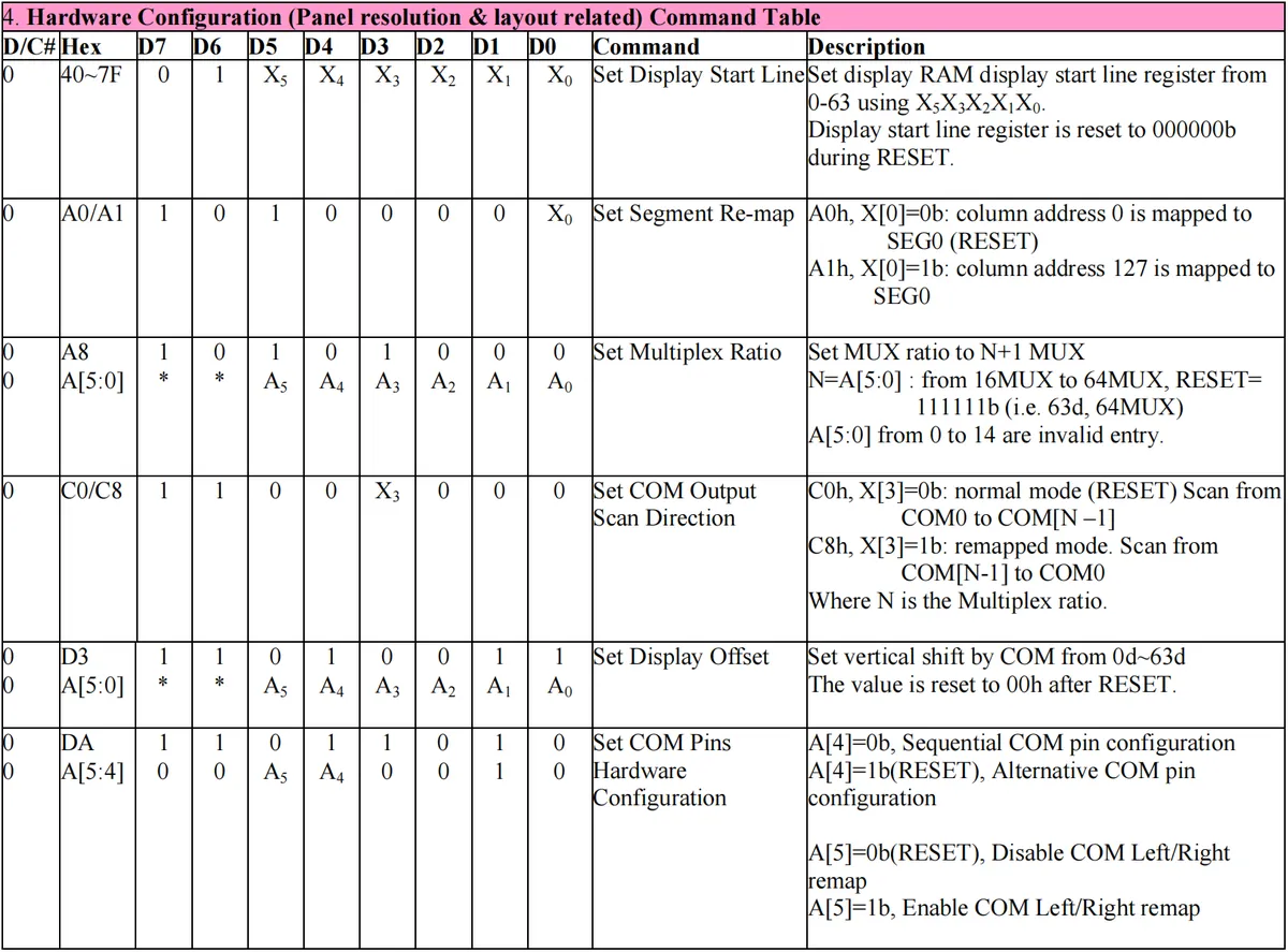
- Hardware Instructions: Instructions related to display functions, including setting the start row of GDDDRAM, COM scanning direction, SEG mapping relationship, etc.
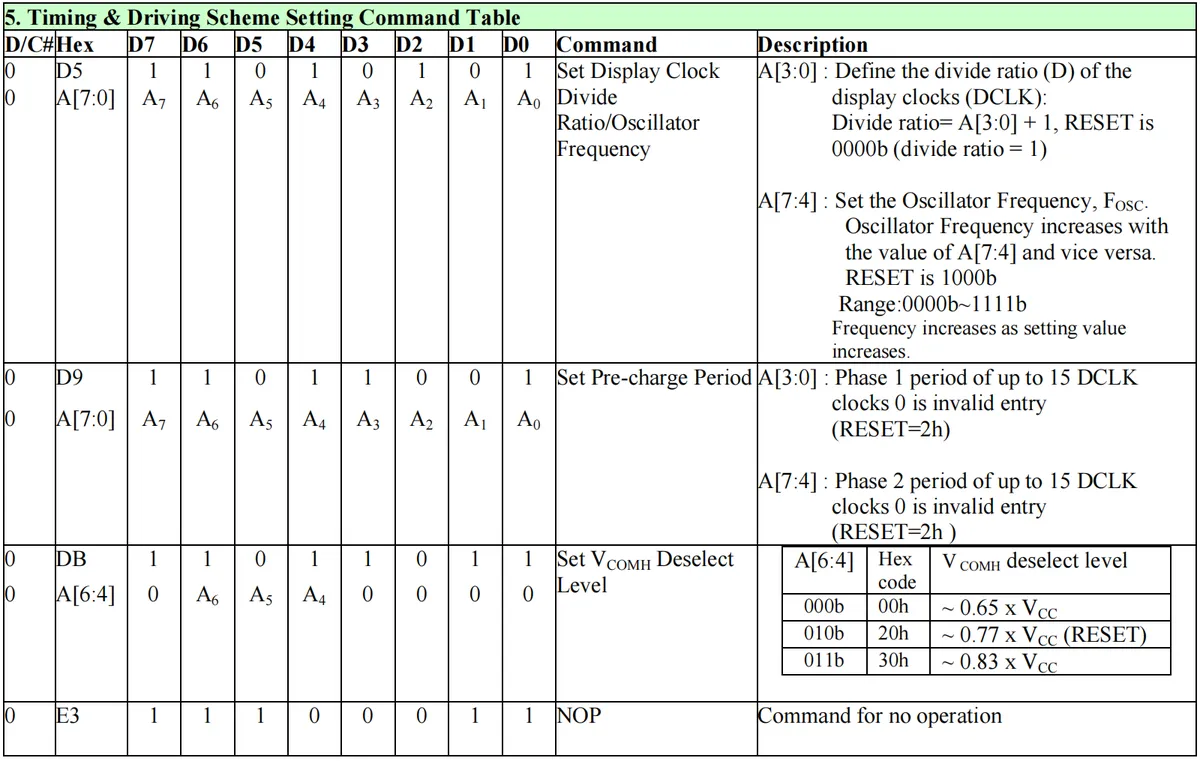
- Timing Commands: Commands related to clock, which configure the display clock division ratio, fosc, precharge period, VCOMH output high level, etc.
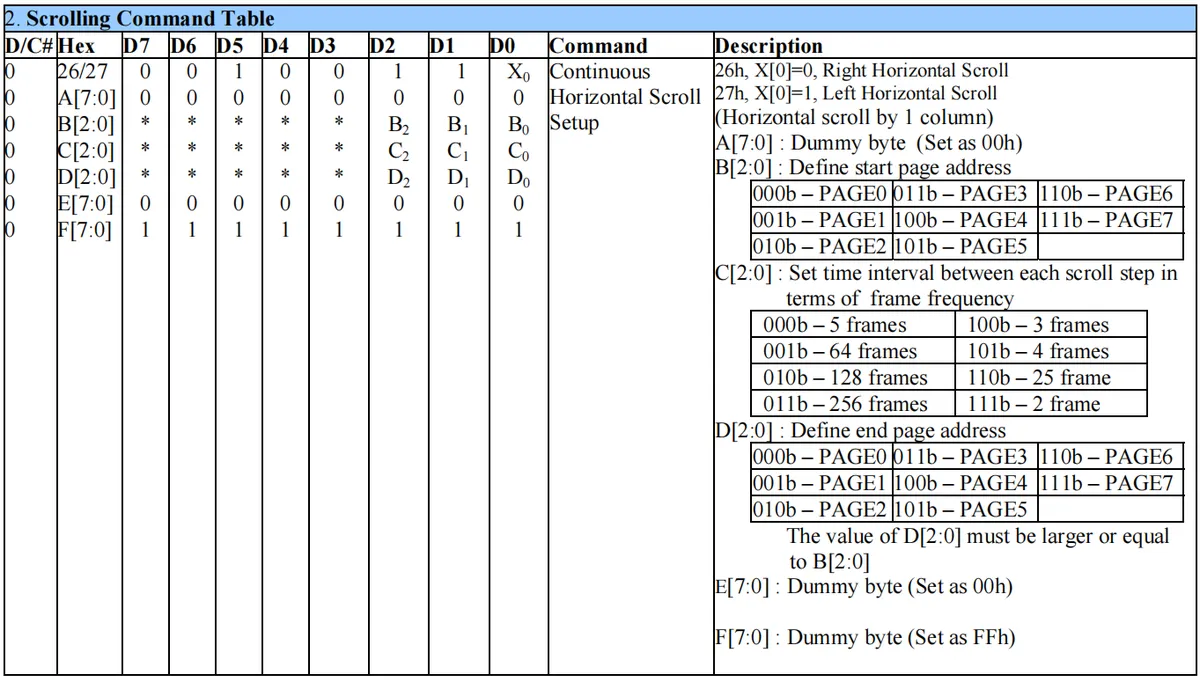
- Scroll commands: These include commands to disable or enable horizontal and vertical scrolling functions, as well as to set parameters such as scrolling area and speed.
For more instructions and their specific meanings, please visit the following link:
https://www.alldatasheet.com/view.jsp?Searchword=Ssd1306
It should be noted here that the slave address of the OLED screen can actually be changed. When using the I2C interface, the SSD1306 supports up to two 7-bit I2C addresses, which can also be switched by pulling the corresponding IO pins low or high. The default address is generally 0x3C. On the back of some modules (not all, as some PCBs do not reserve this design), you can find the I2C address option prompt. To change the I2C address of the module, simply remove the resistor at the indicated position and solder it to the other end. It should be noted that the I2C address marked on the board is the value after adding the 0th read/write bit.
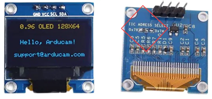
I2C Address Setting
The I2C addresses can be divided into two categories:
- Software Address: When the microcontroller acts as a slave device, its address is specified in the I2C bus address register
- Hardware Address: The address of an I2C peripheral device that is not a microcontroller is entirely determined by the device type and pin levels
The device address of common general-purpose devices with IIC interface consists of the device type and the addressing code, totaling 7 bits (D0 to D7), in the following format:
- Device type: determined by a total of 4 bits from D7 to D4. This type is fixed during production by the semiconductor manufacturer
- User-defined address code: There are 3 bits in total from D3 to D1. This is set by the user; a common practice is that for devices such as EEPROM, it is determined by the combined levels of the 3 pins of the external IC (commonly named A0, A1, A2), which is the addressing code. This also explains why a maximum of 8 chips of the same type can be connected to the same IIC bus for ICs of the same model.
- The least significant bit is the R/W bit:"0" indicates a write operation, and "1" indicates a read operation (usually, a horizontal line above the "write" in read-write signals denotes active low). For this reason, I2C devices typically have two addresses, namely the read address and the write address.
3.1.3 Experiment on Controlling OLED Screen Display
In the following experiment, we need to insert the Fengya No. 1 Board - Universal Compatible Expansion Board into the Fengya No. 1 Board - OLED Display and Interaction Expansion Board, and at the same time turn on the Fengya No. 1 Board - OLED Display and Interaction Expansion Board 's SWITCH1 DIP switch' s I2C_SDA and I2C_SCL options:
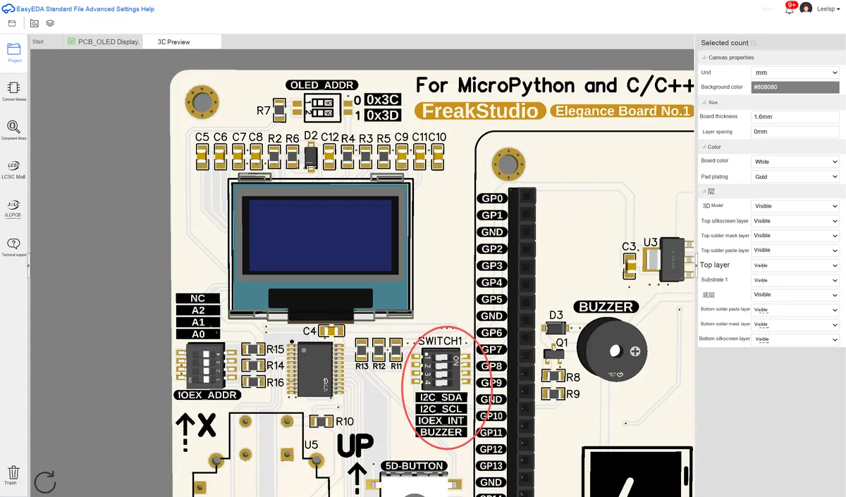
In addition, please select an address on the OLED_ADDR DIP switch. This example sets the switch to 0x3C, so the OLED screen's I²C address is 0x3C:
Here, the pins we use are shown in the following table:
| Device | Pin (Raspberry Pi Pico) | Function / OLED Pin | Peripheral number / parameter used |
|---|---|---|---|
| OLED (I2C SDA) | GPIO6 (GP6) | SDA (serial data line) | I2C id = 1, freq=400000 (400 kHz) |
| OLED (I2C SCL) | GPIO7 (GP7) | SCL (serial clock line) | I2C id = 1, freq=400000 (400 kHz) |
| OLED (power) | 3V3 (Pico 3.3V) | VCC / positive power | — |
| OLED (ground) | GND (Pico GND) | GND / negative power | — |
| OLED (I2C address select) | OLED_ADDR DIP switch | I²C slave address select, can be set to 0x3C (this example) or 0x3D | OLED address = 0x3C (example) |
First, we need to write I2C driver SSD1306 chip methods. Here, we first define a SSD1306 class that inherits from the framebuf.FrameBuffer class; we need to import this module first, the code is as follows:
# Python env   : MicroPython v1.23.0
# -*- coding: utf-8 -*-
# @Time    : 2024/7/2 7:33 PM
# @Author  : Li Qingshui
# @File    : main.py
# @Description : I2C class experiment, mainly using the I2C class to control an OLED screen (SSD 1306, 0.96 inch) by writing data

# ======================================== Import Modules =========================================

# Hardware-related modules
from machine import I2C, Pin
# MicroPython-related modules
from micropython import const
# Time-related modules
import time
# Frame buffer-related modules
import framebuf

# ======================================== Global Variables ============================================

# Constant definitions, used to control various operations of the OLED screen
SET_CONTRAST        = const(0x81)  # Set contrast, range 0x00 - 0xFF
SET_ENTIRE_ON       = const(0xA4)  # Turn on the entire screen
SET_NORM_INV        = const(0xA6)  # Set normal/inverted display mode; in normal mode a high level lights a pixel and a low level turns it off
SET_DISP            = const(0xAE)  # Control screen on/off
SET_MEM_ADDR        = const(0x20)  # Set page addressing mode
SET_COL_ADDR        = const(0x21)  # Set column address
SET_PAGE_ADDR       = const(0x22)  # Set page address
SET_DISP_START_LINE = const(0x40)  # Set start line
SET_SEG_REMAP       = const(0xA0)  # Set segment remap
SET_MUX_RATIO       = const(0xA8)  # Set number of display rows
SET_COM_OUT_DIR     = const(0xC0)  # Set COM output direction
SET_DISP_OFFSET     = const(0xD3)  # Set display offset
SET_COM_PIN_CFG     = const(0xDA)  # Set COM pin configuration
SET_DISP_CLK_DIV    = const(0xD5)  # Set display clock divide ratio
SET_PRECHARGE       = const(0xD9)  # Set pre-charge period
SET_VCOM_DESEL      = const(0xDB)  # Set VCOMH voltage
SET_CHARGE_PUMP     = const(0x8D)  # Set charge pump

# OLED screen address
OLED_ADDRESS = 0

# ======================================== Functions ============================================

# ======================================== Custom Classes ============================================

# SSD1306 OLED screen class
class SSD1306(framebuf.FrameBuffer):
    """
    SSD1306 OLED screen class, used to control the OLED screen and display data on it.

    This class inherits from the `framebuf.FrameBuffer` class and can communicate with the OLED screen over I2C or SPI,
    and perform various display operations, including initialization, turning the display on/off, adjusting contrast, drawing graphics, etc.

    Attributes:
        width (int): Screen width (pixels).
        height (int): Screen height (pixels).
        external_vcc (bool): Whether to use an external power supply.
        buffer (bytearray): Buffer that stores the screen display data.
        pages (int): Number of screen pages, usually height // 8.

    Methods:
        __init__(width: int, height: int, external_vcc: bool) -> None:
            Initialize the OLED screen and configure the display parameters.
        init_display() -> None:
            Initialize the display settings.
        poweroff() -> None:
            Turn off the OLED display.
        poweron() -> None:
            Turn on the OLED display.
        contrast(contrast: int) -> None:
            Set the OLED screen contrast.
        invert(invert: bool) -> None:
            Set the OLED display to inverted or normal display mode.
        show() -> None:
            Update the data in the buffer to the screen.
        write_cmd(cmd: int) -> None:
            Send a command byte to the OLED.
        write_data(buf: bytearray) -> None:
            Send a data byte to the OLED.
    """

    def __init__(self, width: int, height: int, external_vcc: bool) -> None:
        """
        Initialize the OLED screen display.

        Args:
            width (int): Screen width (pixels).
            height (int): Screen height (pixels).
            external_vcc (bool): Whether to use an external power supply.
        """
        self.width = width
        self.height = height
        self.external_vcc = external_vcc
        self.pages = self.height // 8
        # Byte array that stores the image data to be displayed on the screen
        self.buffer = bytearray(self.pages * self.width)
        # Initialize the parent class framebuf.FrameBuffer
        # Constructor of the framebuf.FrameBuffer class
        # framebuf.FrameBuffer.__init__(self, buffer, width, height, format, stride, mapper)
        # Add self.buffer to the data buffer to hold I2C data/command bytes
        # framebuf.MONO_VLSB: indicates monochrome (black and white) display with the least significant bit first (little-endian byte order)
        super().__init__(self.buffer, self.width, self.height, framebuf.MONO_VLSB)
        self.init_display()

    def init_display(self) -> None:
        """
        Initialize the display settings of the OLED screen.

        When the screen is initialized, a series of commands is sent to set display parameters such as display mode, number of rows, and contrast.
        """
        for cmd in (
            SET_DISP | 0x00,            # Turn off the screen
            SET_MEM_ADDR,               # Set page addressing mode
            0x00,                       # Horizontal address auto-increment
            # Resolution and layout settings
            SET_DISP_START_LINE | 0x00, # Set GDDRAM start line to 0
            SET_SEG_REMAP | 0x01,       # Column address 127 mapped to SEG0
            SET_MUX_RATIO,              # Set number of display rows
            self.height - 1,            # Display 128 rows
            SET_COM_OUT_DIR | 0x08,     # Scan from COM[N] to COM0
            SET_DISP_OFFSET,            # Set vertical display offset (upward)
            0x00,                       # Offset 0 rows
            SET_COM_PIN_CFG,            # Set COM pin configuration
            0x02 if self.width > 2 * self.height else 0x12, # Sequential COM configuration, disable left/right remap
            # Timing and drive scheme settings
            SET_DISP_CLK_DIV,           # Set clock divider
            0x80,                       #  No division, level 8 OSC frequency
            SET_PRECHARGE,              # Set pre-charge period
            0x22 if self.external_vcc else 0xF1,            # Disable external power supply
            SET_VCOM_DESEL,             # Set VCOMH voltage
            0x30,                       # 0.83*Vcc
            # Display settings
            SET_CONTRAST,
            0xFF,                       # Set to maximum contrast, level 255
            SET_ENTIRE_ON,              # Output follows RAM content
            SET_NORM_INV,               # Non-inverted display
            SET_CHARGE_PUMP,            # Charge pump settings
            0x10 if self.external_vcc else 0x14, # Enable charge pump
            SET_DISP | 0x01,            # Turn on the screen
        ):
            # Send commands one by one
            # The write_cmd(cmd) method sends commands to the OLED screen
            # Implemented by subclasses inheriting from the SSD1306 class; the implementation differs depending on the communication method
            # write_cmd can send via the SPI peripheral or the I2C peripheral
            self.write_cmd(cmd)
        # Clear the screen
        self.fill(0)
        # Display the data in the buffer on the OLED screen
        self.show()

    def poweroff(self) -> None:
        """
        Turn off the OLED display.

        Turn off the screen display to save power.
        """

        self.write_cmd(SET_DISP | 0x00)

    def poweron(self) -> None:
        """
        Turn on the OLED display.

        Reactivate the OLED display.
        """

        self.write_cmd(SET_DISP | 0x01)

    def contrast(self, contrast: int) -> None:
        """
        Set the contrast of the OLED screen.

        Args:
            contrast (int): Contrast value, in the range 0 to 255.
        """

        self.write_cmd(SET_CONTRAST)
        self.write_cmd(contrast)

    def invert(self, invert: bool) -> None:
        """
        Set the OLED screen to normal or inverted display mode.

        Args:
            invert (bool): If True, the display mode is inverted; otherwise, normal display.
        """

        self.write_cmd(SET_NORM_INV | (invert & 1))

    def show(self) -> None:
        """
        Update the data in the buffer to the screen.

        Send the graphics data stored in the buffer to the OLED screen for display.
        """

        # Calculate the start and end columns of the display area
        x0 = 0
        x1 = self.width - 1
        if self.width == 64:
            # A screen with a width of 64 pixels requires shifting the display position left by 32 pixels
            x0 += 32
            x1 += 32

        # Send the column address setting command to the OLED screen
        self.write_cmd(SET_COL_ADDR)
        self.write_cmd(x0)
        self.write_cmd(x1)

        # Send the page address setting command to the OLED screen
        self.write_cmd(SET_PAGE_ADDR)
        self.write_cmd(0)
        self.write_cmd(self.pages - 1)

        # Send the data display command to the OLED screen to write the data in the buffer to the screen
        self.write_data(self.buffer)

    def write_cmd(self, cmd: int) -> None:
        """
        Send a command to the OLED screen.

        Args:
            cmd (int): The command byte to send.
        """

        pass

    def write_data(self, buf: bytearray) -> None:
        """
        Send data to the OLED screen.

        Args:
            buf (bytearray): The data bytes to send.
        """

        pass
Here, the framebuf module provides a general-purpose frame buffer that can be used to create bitmap images, which can then be sent to a display module. The framebuf module's FrameBuffer class provides a pixel buffer that we can use to draw graphics such as pixels, lines, rectangles, ellipses, polygons, and text.
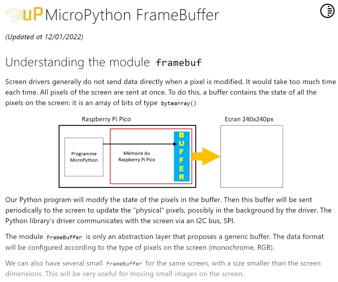
Our custom SSD1306 class has the following methods:
- Initialization: It accepts three parameters: the width and height of the display screen, and a flag indicating whether to use an external VCC power supply. Then, it creates a byte array buffer with the size of height // 8 * width, which is used to store the image data to be displayed on the screen. Next, it calls the constructor of the parent class framebuf.FrameBuffer and passes the buffer as a parameter to it. Finally, it calls the init_display method to initialize the OLED display screen.The constructor and entry parameters of framebuf.FrameBuffer are defined as follows:
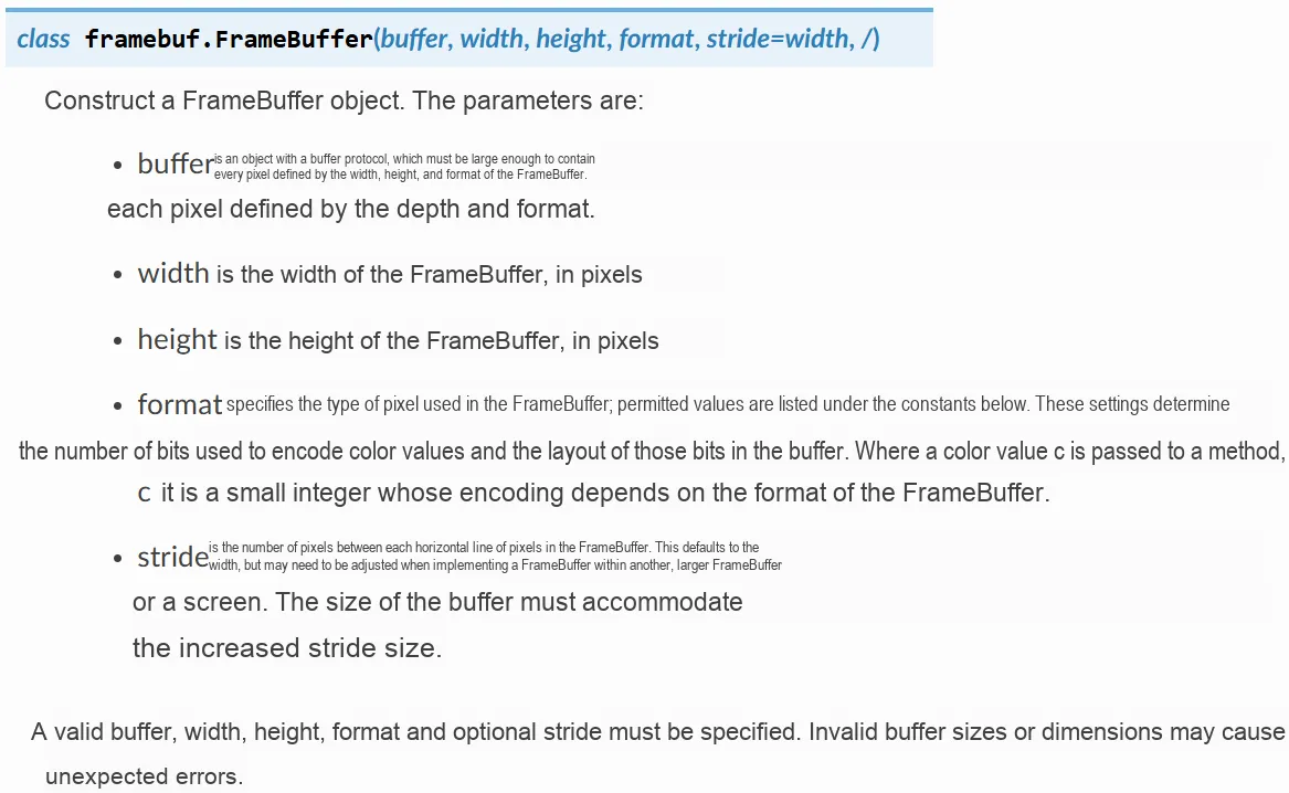
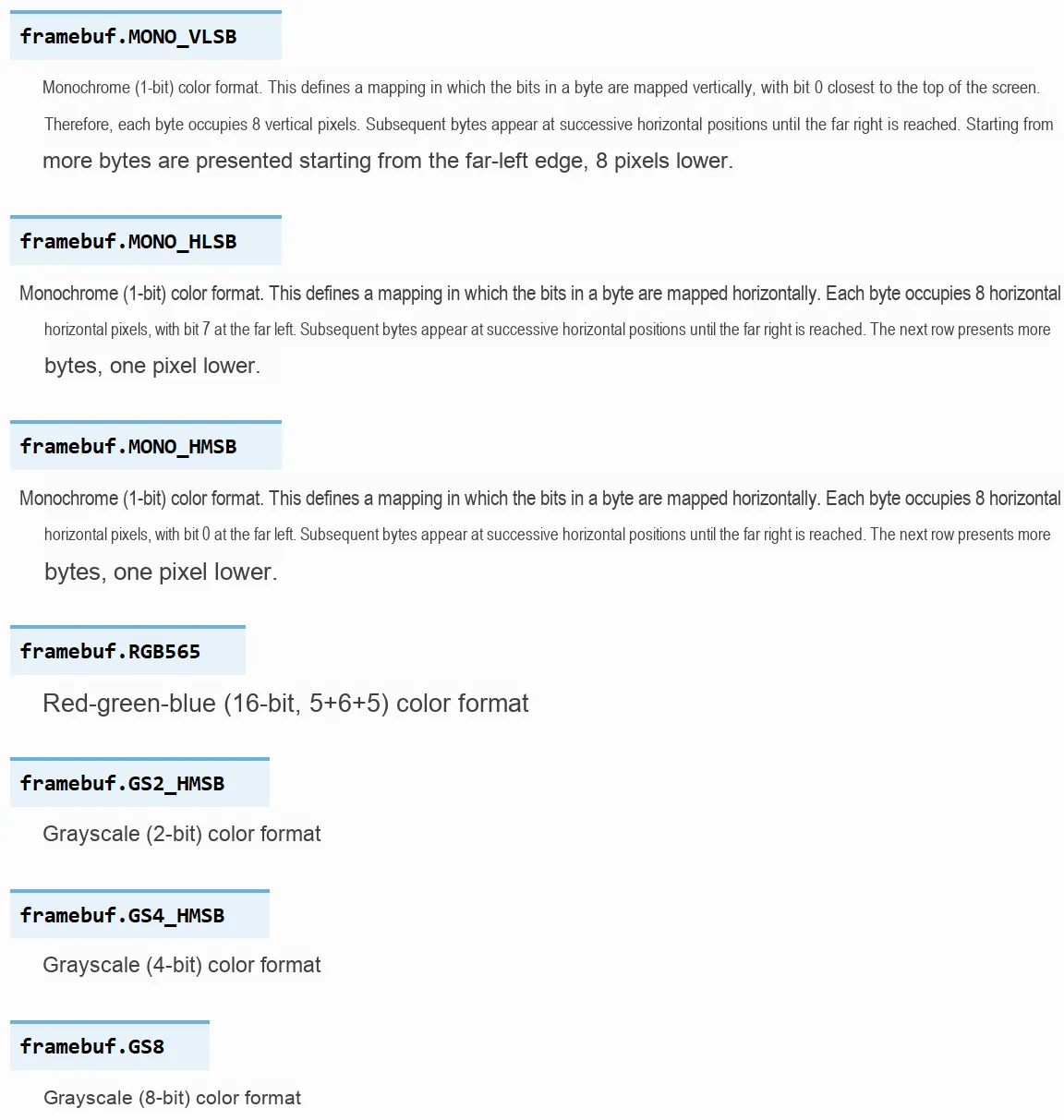
- Configure the display: use the
init_display ()method of the SSD1306 object to configure the display. This method sends a series of commands to the display to set parameters such as resolution, contrast, and brightness. After initialization is complete, it fills the entire screen with black and displays the data in the buffer on the screen. Here, commands are declared using const (), which works similarly to #define in C; when variables declared with const () are compiled into bytecode, the compiler replaces the identifiers with numerical values.This avoids dictionary lookups at runtime. - Display Content: Use the methods inherited from the parent class FrameBuffer of the SSD1306 object to display content, including text, rectangles, circles, etc.
Methods of the FrameBuffer class | Method Description |
FrameBuffer.fill(c) | Fill the entire FrameBuffer with the specified color. The meanings of the parameters are as follows:
|
FrameBuffer.pixel(x, y[, c]) | It is used to draw a pixel at the specified position, with the color determined by parameter c. The meanings of the parameters are as follows:
|
FrameBuffer.hline(x, y, w, c) | Used to draw horizontal lines, the parameters are defined as follows
|
FrameBuffer.vline (x, y, h, c) | Used to draw vertical lines; the parameters are defined as follows
|
FrameBuffer.line(x1, y1, x2, y2, c) | Draw a straight line on the screen, with the color determined by the parameter col; the meanings of the parameters are as follows:
|
FrameBuffer.rect(x, y, w, h, c[, f]) | Draw a rectangle on the screen, with its color determined by the parameter col; the description of the parameter is as follows:
|
FrameBuffer.ellipse (x, y, xr, yr, c[, f, m]) | Draw an ellipse, with its color determined by the parameter col, whose parameters are defined as follows:
|
FrameBuffer.poly(x, y, coords, c[, f]) | Draw a closed shape. The meanings of the parameters are as follows:
|
FrameBuffer.text(s, x, y[, c]) | Draw text, the parameters are defined as follows:
|
FrameBuffer.scroll(xstep, ystep) | Move the content of the FrameBuffer by a given step:
|
FrameBuffer.blit (fbuf, x, y, key=-1, palette=None) | Draw another framebuffer on top of the current framebuffer at the given coordinates. |
- Update Display: After modifying the content of the display, you need to call the show () method of the SSD1306 object to update the display. This method will send the data in the buffer to the display to show the latest content.
- Turn the display on/off: When using the display screen, you can apply the poweron () method to send a command to turn on the display. After all operations are completed, you should call the poweroff () method of the SSD1306 object to turn off the display to save power.
- Set screen contrast: Use the contrast () method to set the contrast of the OLED screen, with a range of 0~255
- Set screen inverted display: Use the invert () method to set the display mode of the OLED screen to normal or inverted
- Write data or commands via IIC: Send data and commands via the write_cmd (cmd) and write_data (buf) methods, which are to be implemented by subclasses via overriding and are not implemented in the SSD1306 class
Considering that the SSD1306 chip supports both I2C and SPI communication, the display function and communication function of the SSD1306 chip are actually separated here, and the display function does not need to concern about what communication interface is used. Therefore, the write_cmd (cmd) and write_data (buf) methods in the SSD1306 class are not implemented, but are implemented by the SSD1306_I2C class that inherits from the SSD1306 class, so as to achieve the decoupling of the communication function and the display function:
- SSD1306_I2C Class: It is mainly responsible for handling communication with the I2C bus, including operations such as initialization, data reading and writing.
- SSD1306 class: it is based on the framebuf module and provides higher-level interfaces such as fill, pixel, scroll and text methods for drawing graphics and text on OLED displays
Writing code for the two modules separately has the following advantages:
- Facilitates code reuse: If support for other communication methods (such as SPI communication) is required in the future, you only need to define another SSD1306_SPI subclass, then override the write_cmd (cmd) and write_data (buf) methods using the function in the machine.SPI library. Similarly, if you need to use the SSD1306 module to draw graphics and text in other projects, you can directly reference this module without concerning yourself with the underlying communication details.
- Facilitates code debugging and maintenance: When issues arise, it becomes easier to pinpoint the root cause — for example, determining whether the problem lies in I2C communication or the rendering logic of the OLED display. Meanwhile, if you need to optimize or modify a specific module, it will not affect the functionality of other modules.
Here, the SSD1306_I2C class inherits from the SSD1306 class, and implements the function of sending data and commands to the OLED screen via the I2C protocol. In the __init__ method of the SSD1306_I2C class, it accepts an additional parameter i2c, which represents the I2C bus object. In the write_cmd and write_data methods, it overrides the methods of the parent class, and uses the I2C bus object to send commands and data. The sample code is as follows:
class SSD1306_I2C(SSD1306):
    """
    SSD1306 OLED screen class based on the I2C interface, inheriting from the `SSD1306` class.

    Communicates with the SSD1306 OLED screen over the I2C bus, providing display control and graphics drawing functions.

    Attributes:
        i2c (I2C): The I2C object used to communicate with the screen.
        addr (int): The I2C address of the OLED screen.

    Methods:
        __init__(i2c: I2C, addr: int, width: int, height: int, external_vcc: bool) -> None:
            Initialize the I2C interface and configure the OLED screen.
        write_cmd(cmd: int) -> None:
            Send a command to the OLED.
        write_data(buf: bytearray) -> None:
            Send data to the OLED.
    """

    def __init__(self, i2c: I2C, addr: int, width: int, height: int, external_vcc: bool) -> None:
        """
        Initialize the I2C interface and the OLED screen.

        Args:
            i2c (I2C): The I2C object used to communicate with the screen.
            addr (int): The I2C address of the OLED screen.
            width (int): Screen width (pixels).
            height (int): Screen height (pixels).
            external_vcc (bool): Whether to use an external power supply.
        """

        self.i2c = i2c
        self.addr = addr
        # Byte array for temporarily storing data
        self.temp = bytearray(2)
        self.write_list = [b"\x40", None]  # Co=0, D/C#=1
        super().__init__(width, height, external_vcc)

    def write_cmd(self, cmd: int) -> None:
        """
        Send a command byte to the OLED screen.

        Args:
            cmd (int): The command byte to send.
        """

        # 0x80 indicates that the data written is a command
        self.temp[0] = 0x80
        self.temp[1] = cmd
        self.i2c.writeto(self.addr, self.temp)

    def write_data(self, buf: bytearray) -> None:
        """
        Send a data byte to the OLED screen.

        Args:
            buf (bytearray): The data bytes to send.
        """

        self.write_list[1] = buf
        self.i2c.writevto(self.addr, self.write_list)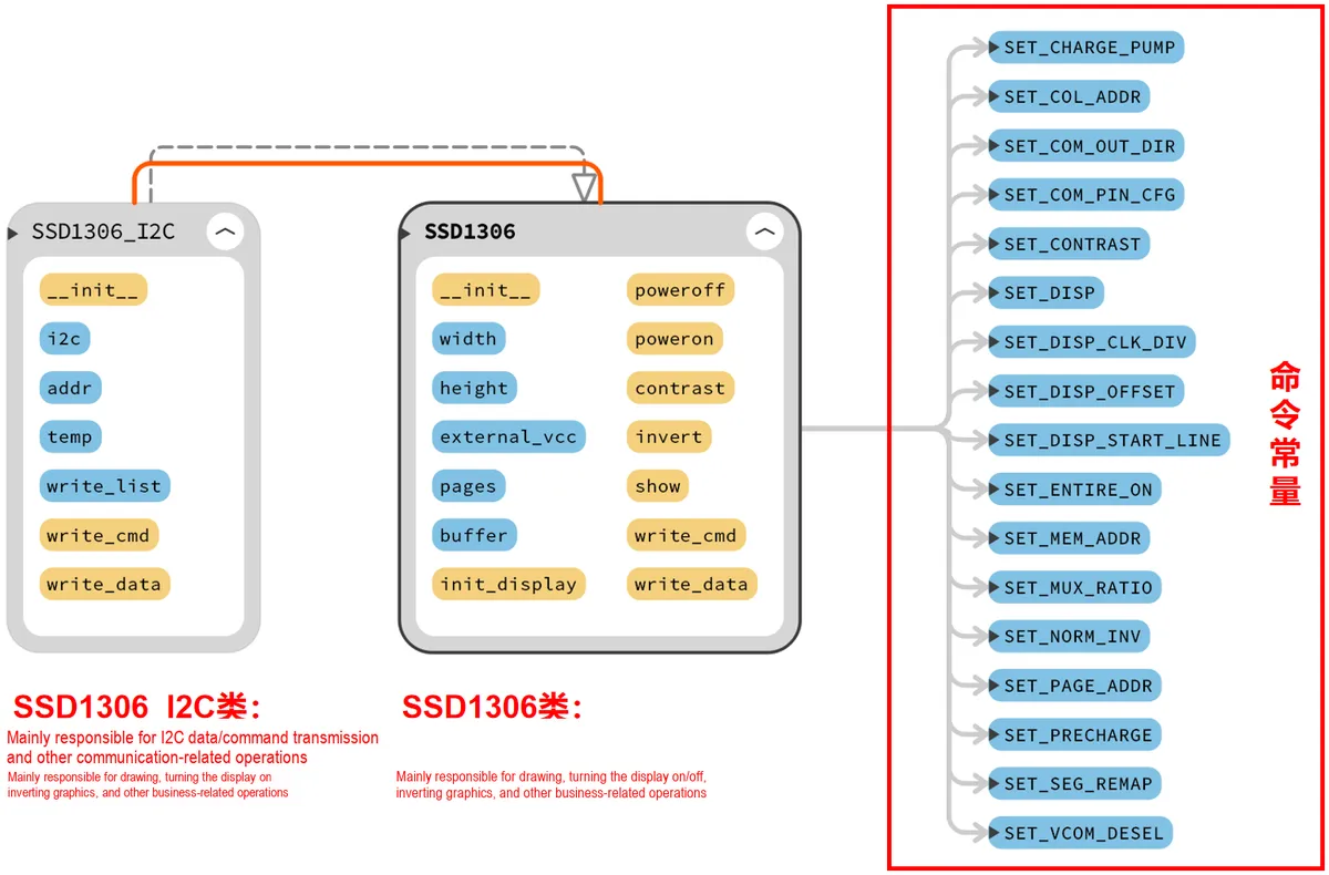
The biggest convenience of using MicroPython is that we don't need to focus on the underlying implementation code of the chips/sensors, and only need to focus on the entire workflow of our project and the writing of the application layer code. Here, you only need to call the driver function we have written to complete the functions required for your own project, and there is no need to delve into the specific details of the underlying implementation.
Next, we can invoke two classes to complete the relevant text and graphics rendering. The process is as follows:
- Initialization Configuration:
- Wait for the device to complete power-on and make sure the OLED display is ready.
- Use the I2C Communication Protocol to scan the devices on the I2C bus and find the address of the OLED display
- Create an instance of the SSD1306 OLED screen, and configure its dimensions, I2C address, and whether to use an external power supply
- Main Program:
- Display the two text strings "Freak Studio" and "OLED Test" in the top-left corner of the screen
- Draw a rectangular outer frame and a filled rectangle
- Draw three vertical straight lines
- Draw two circles with different sizes and fill states
- Draw five points at the center of the screen
- Draw three horizontal straight lines
- Finally, call the
oled.show ()method to display all graphics and text on the OLED screen.
The complete sample code is as follows, which is located in the folder of the supporting materials: elegance-devkit v1\Demo\13 I2C_OLEDShow:
# Python env   : MicroPython v1.23.0
# -*- coding: utf-8 -*-
# @Time    : 2024/7/2 7:33 PM
# @Author  : Li Qingshui
# @File    : main.py
# @Description : I2C class experiment, mainly using the I2C class to control an OLED screen (SSD 1306, 0.96 inch) by writing data

# ======================================== Import Modules =========================================

# Hardware-related modules
from machine import I2C, Pin
# MicroPython-related modules
from micropython import const
# Time-related modules
import time
# Frame buffer-related modules
import framebuf

# ======================================== Global Variables ============================================

# Constant definitions, used to control various operations of the OLED screen
SET_CONTRAST        = const(0x81)  # Set contrast, range 0x00 - 0xFF
SET_ENTIRE_ON       = const(0xA4)  # Turn on the entire screen
SET_NORM_INV        = const(0xA6)  # Set normal/inverted display mode; in normal mode a high level lights a pixel and a low level turns it off
SET_DISP            = const(0xAE)  # Control screen on/off
SET_MEM_ADDR        = const(0x20)  # Set page addressing mode
SET_COL_ADDR        = const(0x21)  # Set column address
SET_PAGE_ADDR       = const(0x22)  # Set page address
SET_DISP_START_LINE = const(0x40)  # Set start line
SET_SEG_REMAP       = const(0xA0)  # Set segment remap
SET_MUX_RATIO       = const(0xA8)  # Set number of display rows
SET_COM_OUT_DIR     = const(0xC0)  # Set COM output direction
SET_DISP_OFFSET     = const(0xD3)  # Set display offset
SET_COM_PIN_CFG     = const(0xDA)  # Set COM pin configuration
SET_DISP_CLK_DIV    = const(0xD5)  # Set display clock divide ratio
SET_PRECHARGE       = const(0xD9)  # Set pre-charge period
SET_VCOM_DESEL      = const(0xDB)  # Set VCOMH voltage
SET_CHARGE_PUMP     = const(0x8D)  # Set charge pump

# OLED screen address
OLED_ADDRESS = 0

# ======================================== Functions ============================================

# ======================================== Custom Classes ============================================

# SSD1306 OLED screen class
class SSD1306(framebuf.FrameBuffer):
    """
    SSD1306 OLED screen class, used to control the OLED screen and display data on it.

    This class inherits from the `framebuf.FrameBuffer` class and can communicate with the OLED screen over I2C or SPI,
    and perform various display operations, including initialization, turning the display on/off, adjusting contrast, drawing graphics, etc.

    Attributes:
        width (int): Screen width (pixels).
        height (int): Screen height (pixels).
        external_vcc (bool): Whether to use an external power supply.
        buffer (bytearray): Buffer that stores the screen display data.
        pages (int): Number of screen pages, usually height // 8.

    Methods:
        __init__(width: int, height: int, external_vcc: bool) -> None:
            Initialize the OLED screen and configure the display parameters.
        init_display() -> None:
            Initialize the display settings.
        poweroff() -> None:
            Turn off the OLED display.
        poweron() -> None:
            Turn on the OLED display.
        contrast(contrast: int) -> None:
            Set the OLED screen contrast.
        invert(invert: bool) -> None:
            Set the OLED display to inverted or normal display mode.
        show() -> None:
            Update the data in the buffer to the screen.
        write_cmd(cmd: int) -> None:
            Send a command byte to the OLED.
        write_data(buf: bytearray) -> None:
            Send a data byte to the OLED.
    """

    def __init__(self, width: int, height: int, external_vcc: bool) -> None:
        """
        Initialize the OLED screen display.

        Args:
            width (int): Screen width (pixels).
            height (int): Screen height (pixels).
            external_vcc (bool): Whether to use an external power supply.
        """
        self.width = width
        self.height = height
        self.external_vcc = external_vcc
        self.pages = self.height // 8
        # Byte array that stores the image data to be displayed on the screen
        self.buffer = bytearray(self.pages * self.width)
        # Initialize the parent class framebuf.FrameBuffer
        # Constructor of the framebuf.FrameBuffer class
        # framebuf.FrameBuffer.__init__(self, buffer, width, height, format, stride, mapper)
        # Add self.buffer to the data buffer to hold I2C data/command bytes
        # framebuf.MONO_VLSB: indicates monochrome (black and white) display with the least significant bit first (little-endian byte order)
        super().__init__(self.buffer, self.width, self.height, framebuf.MONO_VLSB)
        self.init_display()

    def init_display(self) -> None:
        """
        Initialize the display settings of the OLED screen.

        When the screen is initialized, a series of commands is sent to set display parameters such as display mode, number of rows, and contrast.
        """
        for cmd in (
            SET_DISP | 0x00,            # Turn off the screen
            SET_MEM_ADDR,               # Set page addressing mode
            0x00,                       # Horizontal address auto-increment
            # Resolution and layout settings
            SET_DISP_START_LINE | 0x00, # Set GDDRAM start line to 0
            SET_SEG_REMAP | 0x01,       # Column address 127 mapped to SEG0
            SET_MUX_RATIO,              # Set number of display rows
            self.height - 1,            # Display 128 rows
            SET_COM_OUT_DIR | 0x08,     # Scan from COM[N] to COM0
            SET_DISP_OFFSET,            # Set vertical display offset (upward)
            0x00,                       # Offset 0 rows
            SET_COM_PIN_CFG,            # Set COM pin configuration
            0x02 if self.width > 2 * self.height else 0x12, # Sequential COM configuration, disable left/right remap
            # Timing and drive scheme settings
            SET_DISP_CLK_DIV,           # Set clock divider
            0x80,                       #  No division, level 8 OSC frequency
            SET_PRECHARGE,              # Set pre-charge period
            0x22 if self.external_vcc else 0xF1,            # Disable external power supply
            SET_VCOM_DESEL,             # Set VCOMH voltage
            0x30,                       # 0.83*Vcc
            # Display settings
            SET_CONTRAST,
            0xFF,                       # Set to maximum contrast, level 255
            SET_ENTIRE_ON,              # Output follows RAM content
            SET_NORM_INV,               # Non-inverted display
            SET_CHARGE_PUMP,            # Charge pump settings
            0x10 if self.external_vcc else 0x14, # Enable charge pump
            SET_DISP | 0x01,            # Turn on the screen
        ):
            # Send commands one by one
            # The write_cmd(cmd) method sends commands to the OLED screen
            # Implemented by subclasses inheriting from the SSD1306 class; the implementation differs depending on the communication method
            # write_cmd can send via the SPI peripheral or the I2C peripheral
            self.write_cmd(cmd)
        # Clear the screen
        self.fill(0)
        # Display the data in the buffer on the OLED screen
        self.show()

    def poweroff(self) -> None:
        """
        Turn off the OLED display.

        Turn off the screen display to save power.
        """

        self.write_cmd(SET_DISP | 0x00)

    def poweron(self) -> None:
        """
        Turn on the OLED display.

        Reactivate the OLED display.
        """

        self.write_cmd(SET_DISP | 0x01)

    def contrast(self, contrast: int) -> None:
        """
        Set the contrast of the OLED screen.

        Args:
            contrast (int): Contrast value, in the range 0 to 255.
        """

        self.write_cmd(SET_CONTRAST)
        self.write_cmd(contrast)

    def invert(self, invert: bool) -> None:
        """
        Set the OLED screen to normal or inverted display mode.

        Args:
            invert (bool): If True, the display mode is inverted; otherwise, normal display.
        """

        self.write_cmd(SET_NORM_INV | (invert & 1))

    def show(self) -> None:
        """
        Update the data in the buffer to the screen.

        Send the graphics data stored in the buffer to the OLED screen for display.
        """

        # Calculate the start and end columns of the display area
        x0 = 0
        x1 = self.width - 1
        if self.width == 64:
            # A screen with a width of 64 pixels requires shifting the display position left by 32 pixels
            x0 += 32
            x1 += 32

        # Send the column address setting command to the OLED screen
        self.write_cmd(SET_COL_ADDR)
        self.write_cmd(x0)
        self.write_cmd(x1)

        # Send the page address setting command to the OLED screen
        self.write_cmd(SET_PAGE_ADDR)
        self.write_cmd(0)
        self.write_cmd(self.pages - 1)

        # Send the data display command to the OLED screen to write the data in the buffer to the screen
        self.write_data(self.buffer)

    def write_cmd(self, cmd: int) -> None:
        """
        Send a command to the OLED screen.

        Args:
            cmd (int): The command byte to send.
        """

        pass

    def write_data(self, buf: bytearray) -> None:
        """
        Send data to the OLED screen.

        Args:
            buf (bytearray): The data bytes to send.
        """

        pass

class SSD1306_I2C(SSD1306):
    """
    SSD1306 OLED screen class based on the I2C interface, inheriting from the `SSD1306` class.

    Communicates with the SSD1306 OLED screen over the I2C bus, providing display control and graphics drawing functions.

    Attributes:
        i2c (I2C): The I2C object used to communicate with the screen.
        addr (int): The I2C address of the OLED screen.

    Methods:
        __init__(i2c: I2C, addr: int, width: int, height: int, external_vcc: bool) -> None:
            Initialize the I2C interface and configure the OLED screen.
        write_cmd(cmd: int) -> None:
            Send a command to the OLED.
        write_data(buf: bytearray) -> None:
            Send data to the OLED.
    """

    def __init__(self, i2c: I2C, addr: int, width: int, height: int, external_vcc: bool) -> None:
        """
        Initialize the I2C interface and the OLED screen.

        Args:
            i2c (I2C): The I2C object used to communicate with the screen.
            addr (int): The I2C address of the OLED screen.
            width (int): Screen width (pixels).
            height (int): Screen height (pixels).
            external_vcc (bool): Whether to use an external power supply.
        """

        self.i2c = i2c
        self.addr = addr
        # Byte array for temporarily storing data
        self.temp = bytearray(2)
        self.write_list = [b"\x40", None]  # Co=0, D/C#=1
        super().__init__(width, height, external_vcc)

    def write_cmd(self, cmd: int) -> None:
        """
        Send a command byte to the OLED screen.

        Args:
            cmd (int): The command byte to send.
        """

        # 0x80 indicates that the data written is a command
        self.temp[0] = 0x80
        self.temp[1] = cmd
        self.i2c.writeto(self.addr, self.temp)

    def write_data(self, buf: bytearray) -> None:
        """
        Send a data byte to the OLED screen.

        Args:
            buf (bytearray): The data bytes to send.
        """

        self.write_list[1] = buf
        self.i2c.writevto(self.addr, self.write_list)

# ======================================== Initialization ==========================================

# Power-on delay of 3 s
time.sleep(3)
# Print debug message
print("FreakStudio: Using I2C to control OLED display")

# Create a hardware I2C instance using the I2C1 peripheral, clock frequency 400KHz, SDA pin 6, SCL pin 7
i2c = I2C(id=1, sda=Pin(6), scl=Pin(7), freq=400000)

# Start scanning for devices on the I2C bus and return a list of slave addresses
devices_list = i2c.scan()
print('START I2C SCANNER')

# If devices_list is empty, no device is connected to the I2C bus
if len(devices_list) == 0:
    print("No i2c device !")
# If not empty, print the slave device addresses
else:
    print('i2c devices found:', len(devices_list))
    # Iterate over the slave device address list
    for device in devices_list:
        # Check whether the slave device address is 0x3c or 0x3d (i.e., the address of the OLED SSD1306)
        if device == 0x3c or device == 0x3d:
            print("I2C hexadecimal address: ", hex(device))
            OLED_ADDRESS = device

# Create an SSD1306 OLED screen instance, width 128 pixels, height 64 pixels, without external power supply
oled = SSD1306_I2C(i2c, OLED_ADDRESS, 128, 64,False)

# ========================================  Main Program  ============================================

# The (0,0) origin is at the top-left corner of the screen, with the positive x-axis to the right and the positive y-axis downward
# Display text
oled.text('Freak Studio', 20, 5)
oled.text('OLED Test', 25, 15)
# Draw a rectangle outline
oled.rect(0, 0, 128, 64, 1)
# Draw a filled rectangle
oled.fill_rect(5, 25, 118, 5, 1)
# Draw a vertical line
oled.vline(30,35,30,1)
oled.vline(60,35,30,1)
oled.vline(90,35,30,1)
# Draw a circle, filled
oled.ellipse(15, 50, 10, 10,True,1)
# Draw a circle, not filled
oled.ellipse(45, 50, 10, 10,True)
# Draw a point
oled.pixel(65, 50, 1)
oled.pixel(70, 50, 1)
oled.pixel(75, 50, 1)
oled.pixel(80, 50, 1)
oled.pixel(85, 50, 1)
# Draw a horizontal line
oled.hline(95, 50, 30, 1)
oled.hline(95, 45, 30, 1)
oled.hline(95, 40, 30, 1)
# Display an image
oled.show()
Burn the code to the Raspberry Pi Pico, open the remote terminal, and you can see that the slave address of the OLED screen output is 0x3c:
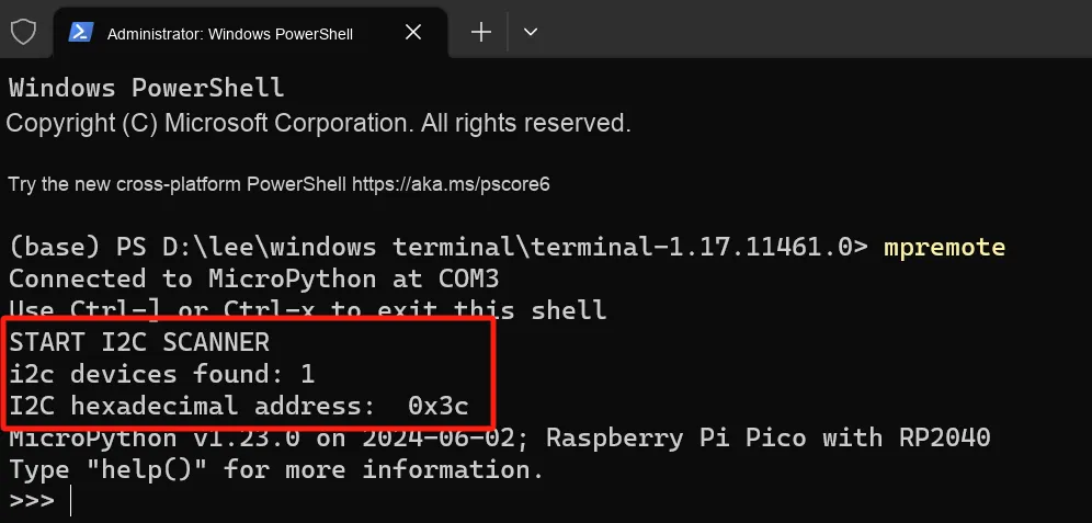
We can see that the graphics displayed on the OLED screen are as follows:
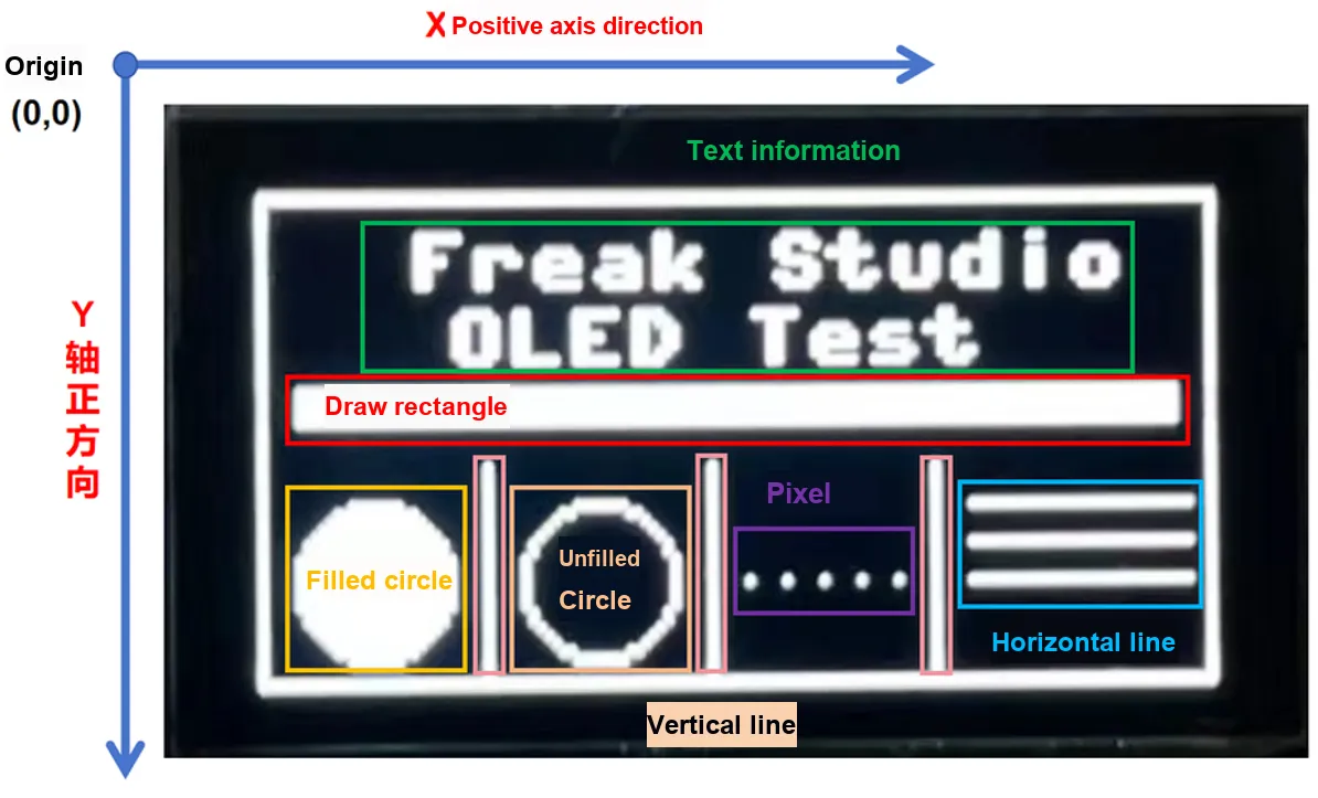
3.2 Experiment of OLED Screen Displaying Serial Port Gyroscope Data
Next, we will use the previously defined OLED screen SSD1306_I2C class and the serial gyroscope IMU class to complete the following tasks:
- Receive the angle data postbacked by the serial port gyroscope
- The OLED screen displays x-axis angle data
- Continuously refresh the x-axis angle data on the OLED screen
3.2.1 Preparations Before the Experiment
In the following experiment, we need to insert the Fengya No. 1 Board - Universal Compatible Expansion Board into the Fengya No. 1 Board - OLED Display and Interaction Expansion Board, and at the same time turn on the Fengya No. 1 Board - OLED Display and Interaction Expansion Board 's SWITCH1 DIP switch' s I2C_SDA and I2C_SCL options:
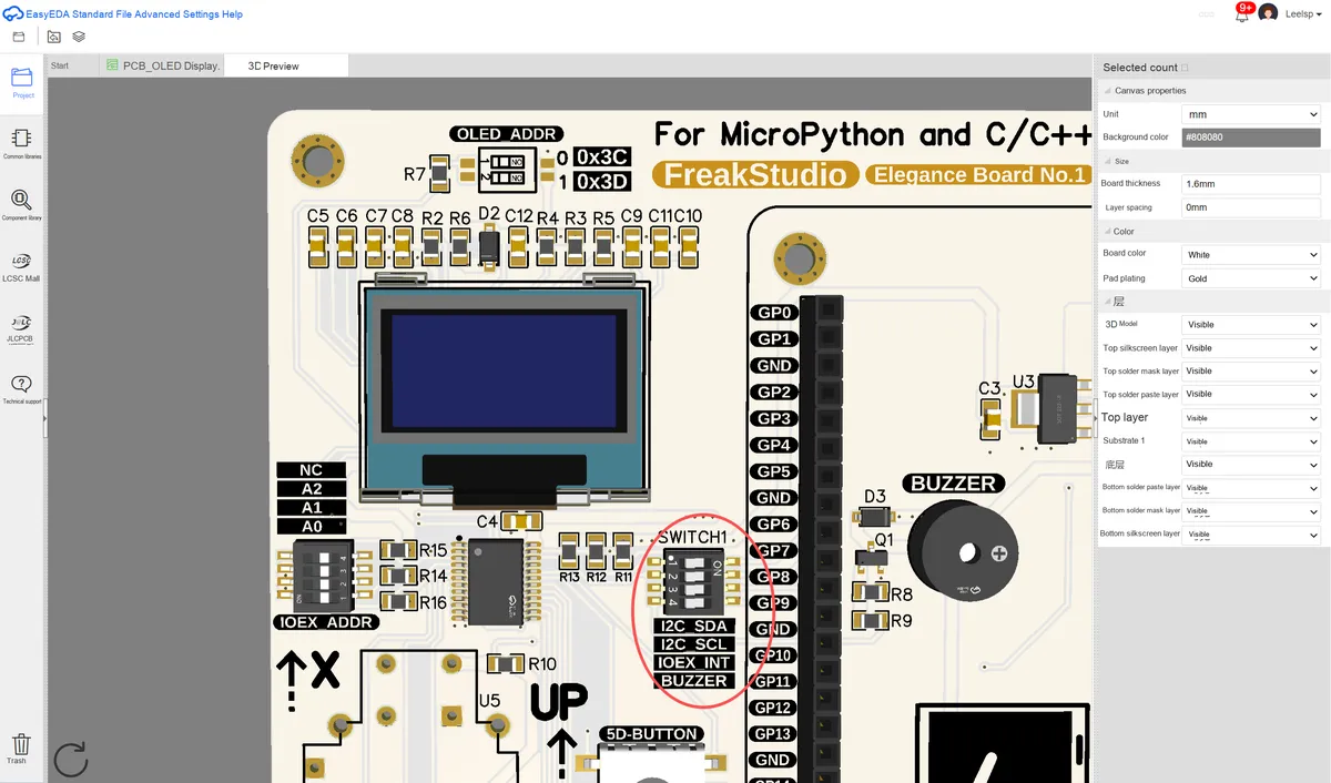
In addition, please select an address on the OLED_ADDR DIP switch. This example sets the switch to 0x3C, so the OLED screen's I²C address is 0x3C:
Then insert the Fengya No. 1 Board - Environment and Storage Acquisition Board into the Fengya No. 1 Board - Universal Compatible Expansion Board, and meanwhile turn on the Fengya No. 1 Board - Environment and Storage Acquisition Board 's SWITCH1 DIP switch' s RXD and TXD options:
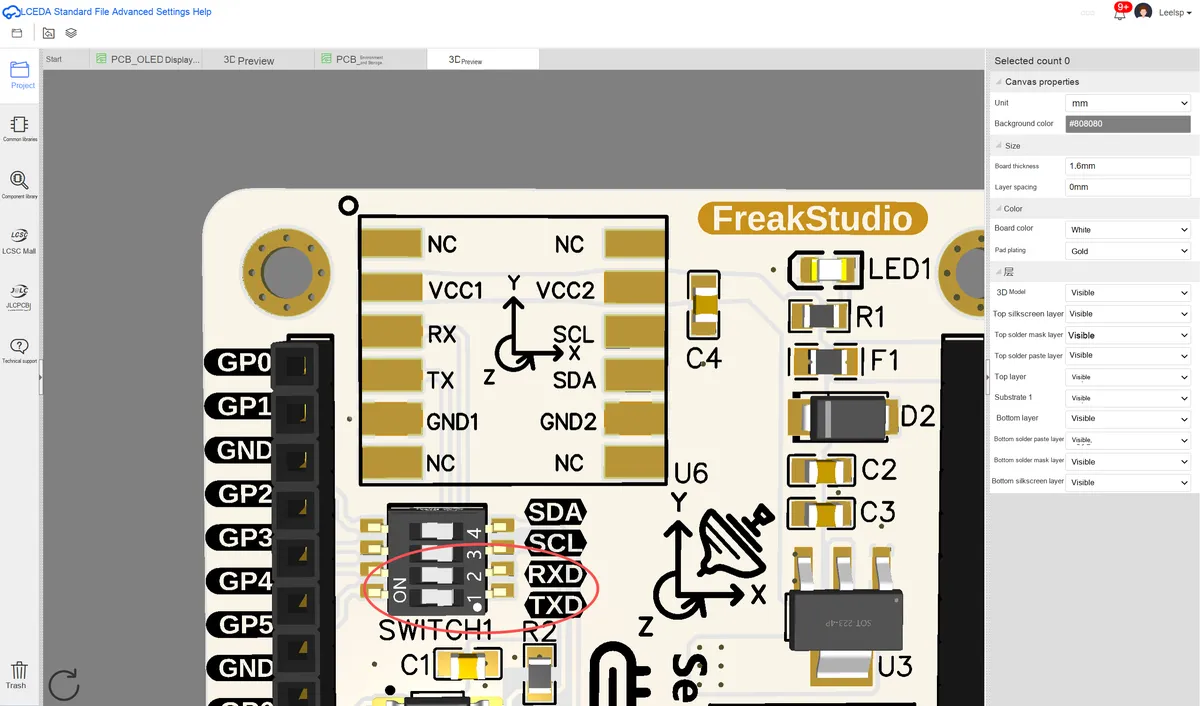
Raspberry Pi Pico and OLED screen module and serial gyroscope module are connected to the pins as shown in the following table:
device | Module Signals / Pins | Pico pins (GPIO) |
OLED screen | SDA | GP6 |
OLED screen | SCL | GP7 |
Serial Port Gyroscope (IMU) | TX (Module → Pico RX) | GP5 |
Serial Port Gyroscope (IMU) | RX (Module ← Pico TX) | GP4 |
Onboard Indicator | LED | GP25 |
3.2.2 Organizing Multiple Python Files: Modules and Packages
For small-scale codebases, we can put all classes in a single file and then add a short snippet at the end of the file to make them interact with each other. However, as the project grows in size, it becomes difficult to locate the specific class we need to modify among the multitude of classes. This is where modules come into play: a module is simply a Python file, nothing more. Each individual file in our program corresponds to one module, and two Python files make up two modules. If we have two files in the same directory, we can import classes from one module into the other for use.
# Import the module named xmoudle
import xmoudle
# Import the xclass class from the xmoudle module
from xmoudle import xclass
Here, we put the SSD1306 class and SSD1306_I2C class related to the operation of OLED display module into the SSD1306.py file, and put the IMU class related to serial gyroscope data reading into the IMU.py file, thus forming two modules. Then we create main.py to import and control different modules to run alternately or exchange data. The import statement is used to import modules or specific classes and functions from a module.By storing functions, variables and classes in separate. py files, you can hide the details of code implementation, reorganize different Code Blocks, separate them from the main program, simplify the logic of the main program and improve its readability.
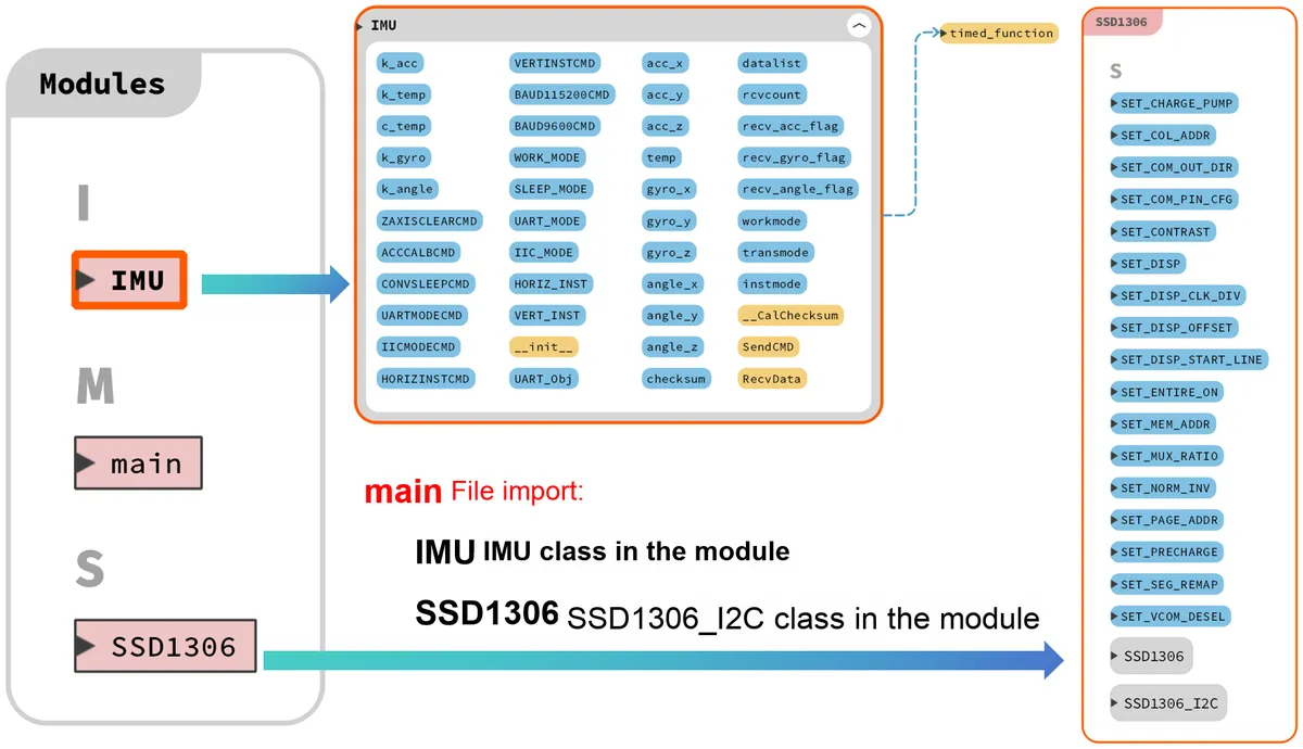
In the main file, we can import a custom module using the following statement:
# Import the SSD1306_I2C class from the SSD1306 module
from SSD1306 import SSD1306_I2C
# Import the IMU class from the IMU module
from IMU import IMU
As the number of modules in a project grows, we might be tempted to add another layer of abstraction to introduce some kind of nested hierarchy at the module level. However, we cannot nest modules inside other modules — after all, one file can only hold one file, and modules are nothing more than Python files.
However, files can be stored in a directory, and so can modules. A package is a collection of modules under a directory, and the name of the package is exactly the name of that directory. We only need to add a file named __init__.py (usually an empty file) in the directory to inform Python that this directory is a package.
Pay attention to the syntax when importing modules or classes between packages. In Python 3, there are two ways to import modules: absolute imports and relative imports.
- Absolute import specifies the full path of the module, function or path we want to import. The import statement uses the period operator to distinguish packages and modules.
- Relative import is basically a way to find classes, functions or modules that have a positional relative relationship with the current module, and it is commonly used to handle related modules under the same package.
For specific usage, please click: https://zhuanlan.zhihu.com/p/376426708
It should be noted here that the code at the module layer will be executed immediately upon import. Developers usually add some test code below the module. To prevent these test codes from being executed after the module is imported, the __name__ attribute can be utilized.
The __name__ attribute is a built-in attribute in Python that stores a string:
- If it is in the current file, name is main;
- If the file is an imported one, name refers to the module name.
When you want to import a certain module but don't want part of the code in that module to be executed directly, you can place that section of code inside the following statement:
# Classes or functions defined by the module

if __name__=='__main__':
    # Code to run in this file; this code is not executed when the file is imported as a module
3.2.3 Flashing Multiple MicroPython Files in One Batch with PyCharm
All the following routine codes can be found in the folder elegance-devkit v1\Demo\14 I2C_ShowIMUData:
Here, we first created the SSD1306.py file, and the code is as follows:
# Python env   : MicroPython v1.23.0
# -*- coding: utf-8 -*-
# @Time    : 2024/7/3 9:34 PM
# @Author  : Li Qingshui
# @File    : SSD1306.py.py
# @Description : Mainly defines the SSD 1306 class


# ======================================== Import Modules ========================================

# MicroPython-related modules
from micropython import const
# Frame buffer-related modules
import framebuf
# Hardware-related modules
from machine import I2C

# ======================================== Global Variables ============================================

# Constant definitions, used to control various operations of the OLED screen
SET_CONTRAST        = const(0x81)  # Set contrast, range 0x00 - 0xFF
SET_ENTIRE_ON       = const(0xA4)  # Turn on the entire screen
SET_NORM_INV        = const(0xA6)  # Set normal/inverted display mode; in normal mode a high level lights a pixel and a low level turns it off
SET_DISP            = const(0xAE)  # Control screen on/off
SET_MEM_ADDR        = const(0x20)  # Set page addressing mode
SET_COL_ADDR        = const(0x21)  # Set column address
SET_PAGE_ADDR       = const(0x22)  # Set page address
SET_DISP_START_LINE = const(0x40)  # Set start line
SET_SEG_REMAP       = const(0xA0)  # Set segment remap
SET_MUX_RATIO       = const(0xA8)  # Set number of display rows
SET_COM_OUT_DIR     = const(0xC0)  # Set COM output direction
SET_DISP_OFFSET     = const(0xD3)  # Set display offset
SET_COM_PIN_CFG     = const(0xDA)  # Set COM pin configuration
SET_DISP_CLK_DIV    = const(0xD5)  # Set display clock divide ratio
SET_PRECHARGE       = const(0xD9)  # Set pre-charge period
SET_VCOM_DESEL      = const(0xDB)  # Set VCOMH voltage
SET_CHARGE_PUMP     = const(0x8D)  # Set charge pump

# ======================================== Functions ============================================

# ======================================== Custom Classes ============================================

# SSD1306 OLED screen class
class SSD1306(framebuf.FrameBuffer):
    """
    SSD1306 OLED screen class, used to control the OLED screen and display data on it.

    This class inherits from the `framebuf.FrameBuffer` class and can communicate with the OLED screen over I2C or SPI,
    and perform various display operations, including initialization, turning the display on/off, adjusting contrast, drawing graphics, etc.

    Attributes:
        width (int): Screen width (pixels).
        height (int): Screen height (pixels).
        external_vcc (bool): Whether to use an external power supply.
        buffer (bytearray): Buffer that stores the screen display data.
        pages (int): Number of screen pages, usually height // 8.

    Methods:
        __init__(width: int, height: int, external_vcc: bool) -> None:
            Initialize the OLED screen and configure the display parameters.
        init_display() -> None:
            Initialize the display settings.
        poweroff() -> None:
            Turn off the OLED display.
        poweron() -> None:
            Turn on the OLED display.
        contrast(contrast: int) -> None:
            Set the OLED screen contrast.
        invert(invert: bool) -> None:
            Set the OLED display to inverted or normal display mode.
        show() -> None:
            Update the data in the buffer to the screen.
        write_cmd(cmd: int) -> None:
            Send a command byte to the OLED.
        write_data(buf: bytearray) -> None:
            Send a data byte to the OLED.
    """

    def __init__(self, width: int, height: int, external_vcc: bool) -> None:
        """
        Initialize the OLED screen display.

        Args:
            width (int): Screen width (pixels).
            height (int): Screen height (pixels).
            external_vcc (bool): Whether to use an external power supply.
        """
        self.width = width
        self.height = height
        self.external_vcc = external_vcc
        self.pages = self.height // 8
        # Byte array that stores the image data to be displayed on the screen
        self.buffer = bytearray(self.pages * self.width)
        # Initialize the parent class framebuf.FrameBuffer
        # Constructor of the framebuf.FrameBuffer class
        # framebuf.FrameBuffer.__init__(self, buffer, width, height, format, stride, mapper)
        # Add self.buffer to the data buffer to hold I2C data/command bytes
        # framebuf.MONO_VLSB: indicates monochrome (black and white) display with the least significant bit first (little-endian byte order)
        super().__init__(self.buffer, self.width, self.height, framebuf.MONO_VLSB)
        self.init_display()

    def init_display(self) -> None:
        """
        Initialize the display settings of the OLED screen.

        When the screen is initialized, a series of commands is sent to set display parameters such as display mode, number of rows, and contrast.
        """
        for cmd in (
            SET_DISP | 0x00,            # Turn off the screen
            SET_MEM_ADDR,               # Set page addressing mode
            0x00,                       # Horizontal address auto-increment
            # Resolution and layout settings
            SET_DISP_START_LINE | 0x00, # Set GDDRAM start line to 0
            SET_SEG_REMAP | 0x01,       # Column address 127 mapped to SEG0
            SET_MUX_RATIO,              # Set number of display rows
            self.height - 1,            # Display 128 rows
            SET_COM_OUT_DIR | 0x08,     # Scan from COM[N] to COM0
            SET_DISP_OFFSET,            # Set vertical display offset (upward)
            0x00,                       # Offset 0 rows
            SET_COM_PIN_CFG,            # Set COM pin configuration
            0x02 if self.width > 2 * self.height else 0x12, # Sequential COM configuration, disable left/right remap
            # Timing and drive scheme settings
            SET_DISP_CLK_DIV,           # Set clock divider
            0x80,                       #  No division, level 8 OSC frequency
            SET_PRECHARGE,              # Set pre-charge period
            0x22 if self.external_vcc else 0xF1,            # Disable external power supply
            SET_VCOM_DESEL,             # Set VCOMH voltage
            0x30,                       # 0.83*Vcc
            # Display settings
            SET_CONTRAST,
            0xFF,                       # Set to maximum contrast, level 255
            SET_ENTIRE_ON,              # Output follows RAM content
            SET_NORM_INV,               # Non-inverted display
            SET_CHARGE_PUMP,            # Charge pump settings
            0x10 if self.external_vcc else 0x14, # Enable charge pump
            SET_DISP | 0x01,            # Turn on the screen
        ):
            # Send commands one by one
            # The write_cmd(cmd) method sends commands to the OLED screen
            # Implemented by subclasses inheriting from the SSD1306 class; the implementation differs depending on the communication method
            # write_cmd can send via the SPI peripheral or the I2C peripheral
            self.write_cmd(cmd)
        # Clear the screen
        self.fill(0)
        # Display the data in the buffer on the OLED screen
        self.show()

    def poweroff(self) -> None:
        """
        Turn off the OLED display.

        Turn off the screen display to save power.
        """

        self.write_cmd(SET_DISP | 0x00)

    def poweron(self) -> None:
        """
        Turn on the OLED display.

        Reactivate the OLED display.
        """

        self.write_cmd(SET_DISP | 0x01)

    def contrast(self, contrast: int) -> None:
        """
        Set the contrast of the OLED screen.

        Args:
            contrast (int): Contrast value, in the range 0 to 255.
        """

        self.write_cmd(SET_CONTRAST)
        self.write_cmd(contrast)

    def invert(self, invert: bool) -> None:
        """
        Set the OLED screen to normal or inverted display mode.

        Args:
            invert (bool): If True, the display mode is inverted; otherwise, normal display.
        """

        self.write_cmd(SET_NORM_INV | (invert & 1))

    def show(self) -> None:
        """
        Update the data in the buffer to the screen.

        Send the graphics data stored in the buffer to the OLED screen for display.
        """

        # Calculate the start and end columns of the display area
        x0 = 0
        x1 = self.width - 1
        if self.width == 64:
            # A screen with a width of 64 pixels requires shifting the display position left by 32 pixels
            x0 += 32
            x1 += 32

        # Send the column address setting command to the OLED screen
        self.write_cmd(SET_COL_ADDR)
        self.write_cmd(x0)
        self.write_cmd(x1)

        # Send the page address setting command to the OLED screen
        self.write_cmd(SET_PAGE_ADDR)
        self.write_cmd(0)
        self.write_cmd(self.pages - 1)

        # Send the data display command to the OLED screen to write the data in the buffer to the screen
        self.write_data(self.buffer)

    def write_cmd(self, cmd: int) -> None:
        """
        Send a command to the OLED screen.

        Args:
            cmd (int): The command byte to send.
        """

        pass

    def write_data(self, buf: bytearray) -> None:
        """
        Send data to the OLED screen.

        Args:
            buf (bytearray): The data bytes to send.
        """

        pass

class SSD1306_I2C(SSD1306):
    """
    SSD1306 OLED screen class based on the I2C interface, inheriting from the `SSD1306` class.

    Communicates with the SSD1306 OLED screen over the I2C bus, providing display control and graphics drawing functions.

    Attributes:
        i2c (I2C): The I2C object used to communicate with the screen.
        addr (int): The I2C address of the OLED screen.

    Methods:
        __init__(i2c: I2C, addr: int, width: int, height: int, external_vcc: bool) -> None:
            Initialize the I2C interface and configure the OLED screen.
        write_cmd(cmd: int) -> None:
            Send a command to the OLED.
        write_data(buf: bytearray) -> None:
            Send data to the OLED.
    """

    def __init__(self, i2c: I2C, addr: int, width: int, height: int, external_vcc: bool) -> None:
        """
        Initialize the I2C interface and the OLED screen.

        Args:
            i2c (I2C): The I2C object used to communicate with the screen.
            addr (int): The I2C address of the OLED screen.
            width (int): Screen width (pixels).
            height (int): Screen height (pixels).
            external_vcc (bool): Whether to use an external power supply.
        """

        self.i2c = i2c
        self.addr = addr
        # Byte array for temporarily storing data
        self.temp = bytearray(2)
        self.write_list = [b"\x40", None]  # Co=0, D/C#=1
        super().__init__(width, height, external_vcc)

    def write_cmd(self, cmd: int) -> None:
        """
        Send a command byte to the OLED screen.

        Args:
            cmd (int): The command byte to send.
        """

        # 0x80 indicates that the data written is a command
        self.temp[0] = 0x80
        self.temp[1] = cmd
        self.i2c.writeto(self.addr, self.temp)

    def write_data(self, buf: bytearray) -> None:
        """
        Send a data byte to the OLED screen.

        Args:
            buf (bytearray): The data bytes to send.
        """

        self.write_list[1] = buf
        self.i2c.writevto(self.addr, self.write_list)

# ======================================== Initialization ==========================================

# ========================================  Main Program  ============================================
Then define the IMU.py file, and the code is as follows:
# Python env   : MicroPython v1.23.0
# -*- coding: utf-8 -*-
# @Time    : 2024/7/3 9:34 PM
# @Author  : Li Qingshui
# @File    : IMU.py
# @Description : Mainly defines the gyroscope IMU class

# ======================================== Import Modules ========================================

# Time-related modules
import time
# Module for binary/ASCII conversion
import binascii
# Hardware-related modules
from machine import UART, Pin

# ======================================== Global Variables ============================================

# ======================================== Functions ============================================

# Timing decorator, used to measure function run time
def timed_function(f: callable, *args: tuple, **kwargs: dict) -> callable:
    """
    Timing decorator, used to measure and print function/method run time.

    Args:
        f (callable): The function/method to be passed in
        args (tuple): Any number of positional arguments passed to function/method f
        kwargs (dict): Any number of keyword arguments passed to function/method f

    Returns:
        callable: Returns the timed function
    """
    myname = str(f).split(' ')[1]

    def new_func(*args: tuple, **kwargs: dict) -> any:
        t: int = time.ticks_us()
        result = f(*args, **kwargs)
        delta: int = time.ticks_diff(time.ticks_us(), t)
        print('Function {} Time = {:6.3f}ms'.format(myname, delta / 1000))
        return result

    return new_func

# ======================================== Custom Classes ============================================

# Six-axis gyroscope class
class IMU:
    """
    Six-axis gyroscope class, responsible for serial communication with the IMU sensor, sending commands and receiving sensor data. The main functions of this class include device calibration, command sending, data receiving, and data parsing, and it supports multiple modes and configuration commands.

    Through this class, the user can control the gyroscope's working mode, transmission mode, and installation mode, and can receive three-axis acceleration, angular velocity (gyroscope data), and angle data (tilt angle). In addition, it provides a command-sending interface, so the user can send various control commands to configure the IMU device.

    Attributes:
        k_acc (int): Conversion coefficient for acceleration data, used to convert raw data to g units.
        k_temp (float): Conversion coefficient for temperature data, used to convert raw data to degrees Celsius.
        c_temp (float): Temperature offset constant, the offset to be added when converting temperature.
        k_gyro (int): Conversion coefficient for angular velocity data, used to convert raw data to degrees per second (°/s).
        k_angle (int): Conversion coefficient for angle data, used to convert raw data to degrees.

        ZAXISCLEARCMD (list): Command used to zero the Z-axis angle.
        ACCCALBCMD (list): Command used to perform acceleration calibration.
        CONVSLEEPCMD (list): Command used to switch the gyroscope between working mode and sleep mode.
        UARTMODECMD (list): Command used to switch to UART transmission mode.
        IICMODECMD (list): Command used to switch to IIC transmission mode.
        HORIZINSTCMD (list): Command used to set the horizontal installation mode.
        VERTINSTCMD (list): Command used to set the vertical installation mode.
        BAUD115200CMD (list): Command used to set the serial baud rate to 115200.
        BAUD9600CMD (list): Command used to set the serial baud rate to 9600.

        WORK_MODE (int): Indicates the working mode of the device (1 for working, 0 for sleeping).
        SLEEP_MODE (int): Indicates the sleep mode of the device (0 for sleeping, 1 for working).
        UART_MODE (int): UART transmission mode (1 for UART mode, 0 for IIC mode).
        IIC_MODE (int): IIC transmission mode (0 for IIC mode, 1 for UART mode).
        HORIZ_INST (int): Horizontal installation mode (1 for horizontal installation mode, 0 for vertical installation mode).
        VERT_INST (int): Vertical installation mode (0 for vertical installation mode, 1 for horizontal installation mode).

    Methods:
        __init__(self, UART_Obj: UART) -> None: Initialize the IMU class, set the UART object, and initialize related parameters.
        SendCMD(self, cmd: list[int]) -> bool: Send a command to the IMU device, used to set the device's working mode, transmission mode, etc.
        ReceiveData(self) -> tuple[float, float, float]: Receive and parse the IMU sensor data, and return the acceleration, angular velocity, and angle data.

    Example Usage:
        imu = IMU(uart_obj)
        imu.SendCMD(IMU.ACCCALBCMD)  # Send the acceleration calibration command
        data = imu.ReceiveData()     # Get the acceleration, angular velocity, and angle data
    """

    # Declare class variables: class variables are shared among all instances of the class and are used to store shared data related to the class

    # The following variables are the coefficients and constants used for gyroscope data conversion
    k_acc = 16
    k_temp = 96.38
    c_temp = 36.53
    k_gyro = 2000
    k_angle = 180

    # The following variables are the data contents of each command
    # Z-axis zeroing command
    ZAXISCLEARCMD = [0XFF, 0XAA, 0X52]
    # Acceleration calibration command
    ACCCALBCMD    = [0XFF, 0XAA, 0X67]
    # Command to switch between sleep mode and working mode
    CONVSLEEPCMD  = [0XFF, 0XAA, 0X60]
    # UART transmission mode command
    UARTMODECMD   = [0XFF, 0XAA, 0X61]
    # IIC transmission mode command
    IICMODECMD    = [0XFF, 0XAA, 0X62]
    # Horizontal installation mode command
    HORIZINSTCMD  = [0XFF, 0XAA, 0x65]
    # Vertical installation mode command
    VERTINSTCMD   = [0XFF, 0XAA, 0x66]
    # Command to set the serial baud rate to 115200
    BAUD115200CMD = [0XFF, 0XAA, 0X63]
    # Command to set the serial baud rate to 9600
    BAUD9600CMD   = [0XFF, 0XAA, 0X64]
    # The bandwidth setting commands are rarely used; leave them for the user to implement as needed
    # ============ Bandwidth protocol ============
    # | HEARDER1 | HEARDER2 |  CMD  |
    # CMD options:
    # 0x81 - Bandwidth 256 Hz
    # 0x82 - Bandwidth 188 Hz
    # 0x83 - Bandwidth 98  Hz
    # 0x84 - Bandwidth 42  Hz
    # 0x85 - Bandwidth 20  Hz
    # 0x86 - Bandwidth 10  Hz
    # 0x87 - Bandwidth 5   Hz
    # Note that after implementing the bandwidth-related commands yourself,
    # you need to add the corresponding class variables to the input parameter check of the self.SendCMD method

    # Class variables representing the working mode
    # WORK_MODE  - Working mode: 1
    # SLEEP_MODE - Sleep mode: 0
    WORK_MODE, SLEEP_MODE = (1, 0)

    # Class variables representing the data transmission mode
    # UART_MODE  - UART transmission mode: 1
    # IIC_MODE   - IIC transmission mode: 0
    UART_MODE, IIC_MODE = (1, 0)

    # Class variables representing the installation mode
    # HORIZ_INST - Horizontal installation mode: 1
    # VERT_INST  - Vertical installation mode: 0
    HORIZ_INST, VERT_INST = (1, 0)

    # Initialization function
    def __init__(self, UART_Obj: UART) -> None:
        """
        Initialize the IMU class, set the UART object, and initialize related parameters.

        Args:
            UART_Obj (UART): UART object used to communicate with the gyroscope

        Returns:
            None
        """

        # IMU class instances and UART class instances are in a composition relationship
        self.UART_Obj: UART = UART_Obj

        # Variables temporarily storing motion data received from the gyroscope
        # Three-axis acceleration data
        self.acc_x: float = 0
        self.acc_y: float = 0
        self.acc_z: float = 0
        # Temperature data
        self.temp: float = 0
        # Three-axis angular velocity data
        self.gyro_x: float = 0
        self.gyro_y: float = 0
        self.gyro_z: float = 0
        # Three-axis angle data
        self.angle_x: float = 0
        self.angle_y: float = 0
        self.angle_z: float = 0

        # UART checksum
        self.checksum: int = 0

        # Temporary buffer list for UART received data
        self.datalist: list[int] = [0] * 15

        # Variable recording the number of UART receptions
        self.rcvcount: int = 0

        # Flags indicating completion of reception for different gyroscope data types
        # 0: not yet received, 1: received
        # Acceleration data reception complete flag
        self.recv_acc_flag: int = 0
        # Angular acceleration data reception complete flag
        self.recv_gyro_flag: int = 0
        # Angle data reception complete flag
        self.recv_angle_flag: int = 0

        # Gyroscope working mode
        self.workmode: int = IMU.WORK_MODE
        # Gyroscope data transmission mode
        self.transmode: int = IMU.UART_MODE
        # Gyroscope installation mode
        self.instmode: int = IMU.HORIZ_INST

        # Note: during calibration and Z-axis angle zeroing, the sensor must be kept level/vertical and stationary
        # Z-axis angle zeroing
        self.SendCMD(IMU.ZAXISCLEARCMD)
        # Acceleration calibration
        self.SendCMD(IMU.ACCCALBCMD)

    # Private method: check whether the checksum is correct
    def __CalChecksum(self) -> bool:
        """
        Calculate the checksum and determine whether it is correct.

        Returns:
            bool: Returns True if the checksum is correct, otherwise False
        """

        # Get the checksum received over the serial port
        self.checksum = self.datalist[10]

        # Declare a temporary checksum
        tempchecksum: int = 0
        # Calculate the checksum
        for i in range(0, 10):
            tempchecksum = tempchecksum + self.datalist[i]

        # Take the low 8 bits of the calculated checksum
        tempchecksum = tempchecksum & 0xff

        # Determine whether the reception is correct
        if tempchecksum != self.checksum:
            return False
        else:
            return True

    # UART command sending function
    def SendCMD(self, cmd: list[int]) -> bool:
        """
        Send a command to the IMU device.

        Args:
            cmd (list[int]): List of commands to send

        Returns:
            bool: Returns True if sent successfully, otherwise False
        """

        # If the command is not defined in the IMU class variables, return False
        if (cmd != IMU.ZAXISCLEARCMD
            and cmd != IMU.ACCCALBCMD
            and cmd != IMU.CONVSLEEPCMD
            and cmd != IMU.UARTMODECMD
            and cmd != IMU.IICMODECMD
            and cmd != IMU.HORIZINSTCMD
            and cmd != IMU.VERTINSTCMD
            and cmd != IMU.BAUD115200CMD
            and cmd != IMU.BAUD9600CMD):

            return False

        # Send the command content
        for data in cmd:
            # In the UART.write(buf) method, buf must support the buffer protocol
            self.UART_Obj.write(bytes([data]))

        # If it is the command to switch between sleep mode and working mode
        if cmd == IMU.CONVSLEEPCMD:
            # Toggle and assign the workmode attribute of self
            if self.workmode == IMU.WORK_MODE:
                self.workmode = IMU.SLEEP_MODE
            else:
                self.workmode = IMU.WORK_MODE

        # If the UART transmission mode command was sent
        if cmd == IMU.UARTMODECMD:
            # The gyroscope data transmission mode is UART transmission mode
            self.transmode = IMU.UART_MODE

        # If the IIC transmission mode command was sent
        if cmd == IMU.IICMODECMD:
            # The gyroscope data transmission mode is IIC transmission mode
            self.transmode = IMU.IIC_MODE

        # If the horizontal installation mode command was sent
        if cmd == IMU.HORIZINSTCMD:
            # The gyroscope installation mode is horizontal installation mode
            self.instmode = IMU.HORIZ_INST

        # If the vertical installation mode command was sent
        if cmd == IMU.VERTINSTCMD:
            # The gyroscope installation mode is vertical installation mode
            self.instmode = IMU.VERT_INST

        # If the command to set the serial baud rate to 115200 was sent
        if cmd == IMU.BAUD115200CMD:
            # Set the serial baud rate to 115200
            self.UART_Obj.init(baudrate = 115200)

        # If the command to set the serial baud rate to 9600 was sent
        if cmd == IMU.BAUD9600CMD:
            # Set the serial baud rate to 9600
            self.UART_Obj.init(baudrate = 9600)

        # If the command is the Z-axis zeroing command or the acceleration calibration command
        if cmd == IMU.ZAXISCLEARCMD or cmd == IMU.ACCCALBCMD:
            # While the gyroscope calibration is in progress, wait 100 ms
            time.sleep_ms(500)

        return True

    # UART data receiving function
    # Use the @timed_function decorator to measure the running time of the IMU.RecvData method
    # When there is no need to measure the running time, simply remove the @timed_function decorator
    @timed_function
    def RecvData(self) -> tuple[float, float, float]:
        """
        Receive and parse the IMU sensor data.

        This method receives three-axis acceleration, angular velocity, and angle data.

        Returns:
            tuple: Returns the three-axis acceleration, angular velocity, and angle data
        """
        # Loop until three frames of data (acceleration, angular velocity, angle) have been received
        while True:
            # Use the UART.any method to check whether there is data
            if self.UART_Obj.any():
                # Receive one UART byte, of type bytes
                tempdata = self.UART_Obj.read(1)
                # Convert the bytes in the data object to hexadecimal representation
                tempdata = binascii.hexlify(tempdata)
                # Convert the hexadecimal bytes object to a decimal integer
                tempdata = int(tempdata, 16)

                # Store the received data item in the datalist list
                self.datalist[self.rcvcount] = tempdata

                # If the received byte is not the frame header 0x55, start receiving again
                if self.datalist[0] != 0x55:
                    # Reset the UART receive count variable to zero
                    self.rcvcount = 0
                # If it is the frame header 0x55, continue receiving
                else:
                    # Increment the UART receive count variable by 1
                    self.rcvcount = self.rcvcount + 1

                    # One frame of data consists of 11 data packets
                    # If the count has not reached 11, reception is not yet complete; continue receiving the next data item
                    if self.rcvcount < 11:
                        continue
                    # One frame of data has been received; start parsing the data
                    # ============================================ Data frame format ============================================
                    # | HEADER | TYPE | DATA0L | DATA0H | DATA1L | DATA1H | DATA2L | DATA2H | DATA3L | DATA3H | SUMCRC |
                    # | 0x55   | x    | x      | x      | x      | x      | x      | x      | x      | x      | x      |
                    # SUMCRC=0x55+TYPE+DATA1L+DATA1H+DATA2L+DATA2H+DATA3L+DATA3H+DATA4L+DATA4H, take the low 8 bits of the checksum, of type char
                    # ============================================ Data frame format ============================================
                    else:
                        # If the checksum is correct, convert the data; otherwise, receive the next frame again
                        if self.__CalChecksum():

                            # If it is acceleration data
                            if self.datalist[1] == 0x51:
                                # Convert the data
                                self.acc_x = (self.datalist[3] << 8 | self.datalist[2]) / 32768 * IMU.k_acc
                                self.acc_y = (self.datalist[5] << 8 | self.datalist[4]) / 32768 * IMU.k_acc
                                self.acc_z = (self.datalist[7] << 8 | self.datalist[6]) / 32768 * IMU.k_acc
                                self.temp = (self.datalist[9] << 8 | self.datalist[8]) / 32768 * IMU.k_temp + IMU.c_temp

                                # Set the acceleration data reception complete flag
                                self.recv_acc_flag = 1

                            # If it is angular velocity data
                            if self.datalist[1] == 0x52:
                                # Convert the data
                                self.gyro_x = (self.datalist[3] << 8 | self.datalist[2]) / 32768 * IMU.k_gyro
                                self.gyro_y = (self.datalist[5] << 8 | self.datalist[4]) / 32768 * IMU.k_gyro
                                self.gyro_z = (self.datalist[7] << 8 | self.datalist[6]) / 32768 * IMU.k_gyro
                                # Set the angular velocity data reception complete flag
                                self.recv_gyro_flag = 1

                            # If it is angle data
                            if self.datalist[1] == 0x53:
                                # Convert the data
                                self.angle_x = (self.datalist[3] << 8 | self.datalist[2]) / 32768 * IMU.k_angle
                                self.angle_y = (self.datalist[5] << 8 | self.datalist[4]) / 32768 * IMU.k_angle
                                self.angle_z = (self.datalist[7] << 8 | self.datalist[6]) / 32768 * IMU.k_angle
                                # Set the angle data reception complete flag
                                self.recv_angle_flag = 1

                            # If all three frames have been received, return the gyroscope data received over a period of time
                            if self.recv_acc_flag == 1 and self.recv_gyro_flag == 1 and self.recv_angle_flag == 1:
                                # Clear the reception complete flags for the three data types
                                self.recv_acc_flag = 0
                                self.recv_gyro_flag = 0
                                self.recv_angle_flag = 0

                                # Return the gyroscope data received over a period of time
                                return self.acc_x, self.acc_y, self.acc_z, self.temp, self.gyro_x, self.gyro_y, self.gyro_z, self.angle_x, self.angle_y, self.angle_z

                        # After receiving a frame, clear the variable counting UART receptions
                        self.rcvcount = 0

# ======================================== Initialization ==========================================

# ========================================  Main Program  ============================================
In the main.py file, the following operations are mainly performed:
- Import Modules: First, the required modules are imported, including the SSD1306_I2C class for controlling the OLED screen, the IMU class for communicating with the gyroscope, as well as the UART, I2C and Pin classes from the machine module for handling hardware operations.
- Global Variables: The global variable OLED_ADDRESS is defined to store the I2C address of the OLED screen.
- Initialization Configuration:
- Wait for 5 seconds to ensure that the device has completed power-on.
- Create an I2C instance and configure its parameters.
- List all files in the current directory.
- Scan the I2C bus to find connected devices and store the addresses of the detected devices.
- Create an SSD1306 OLED screen instance using the found device address.
- Initialize a serial port object and configure its parameters.
- Initialize an LED output pin.
- Initialize an IMU object to communicate with the gyroscope.
- Main Program:
- Draw a rectangular outer frame on the OLED screen and display text.
- Enter an infinite loop and perform the following operations in each iteration:
- Turn on the LED.
- Receive data from the gyroscope.
- Turn off the LED.
- Display the x-axis angle of the gyroscope on the OLED screen.
- Print the x-axis angle and the number of bytes of remaining RAM.
- If the remaining RAM is less than 80,000 bytes, manually trigger garbage collection.
- Clear the specified rectangular area on the OLED screen.
The sample code is as follows:
# Python env   : MicroPython v1.23.0
# -*- coding: utf-8 -*-
# @Time    : 2024/7/3 9:34 PM
# @Author  : Li Qingshui
# @File    : main.py
# @Description : I2C class experiment, mainly reads the serial gyroscope data and displays it on the OLED screen

# ======================================== Import Modules ========================================

# Import the SSD1306_I2C class from the SSD1306 module
from SSD1306 import SSD1306_I2C
# Import the IMU class from the IMU module
from IMU import IMU
# Hardware-related modules
from machine import UART, I2C, Pin
# Import time-related modules
import time
# System-related modules
import os
# Garbage collection module
import gc

# ======================================== Global Variables ============================================

# OLED screen address
OLED_ADDRESS = 0

# ======================================== Functions ============================================

# ======================================== Custom Classes ============================================

# ======================================== Initialization ==========================================

# Delay 3 s to wait for the device to finish powering up
time.sleep(3)
# Print debug message
print("FreakStudio: Using OLED Screen with I2C to show IMU data")

# Create a hardware I2C instance using the I2C1 peripheral, clock frequency 400KHz, SDA pin 6, SCL pin 7
i2c = I2C(id=1, sda=Pin(6), scl=Pin(7), freq=400000)

# Output all files in the current directory
print('START LIST ALL FILES')
for file in os.listdir():
    print('file name:',file)

# Start scanning for devices on the I2C bus and return a list of slave addresses
devices_list = i2c.scan()
print('START I2C SCANNER')

# If devices_list is empty, no device is connected to the I2C bus
if len(devices_list) == 0:
    print("No i2c device !")
# If not empty, print the slave device addresses
else:
    print('i2c devices found:', len(devices_list))
    # Iterate over the slave device address list
    for device in devices_list:
        # Check whether it is the address of the OLED screen
        if device == 0x3c or device == 0x3d:
            print("I2C hexadecimal address: ", hex(device))
            OLED_ADDRESS = device

# Create an SSD1306 OLED screen instance, width 128 pixels, height 64 pixels, without external power supply
oled = SSD1306_I2C(i2c, OLED_ADDRESS, 128, 64,False)
# Print a prompt message
print('OLED init success')

# Create the serial port object, set the baud rate to 115200
uart = UART(1, 115200)
# Initialize the uart object: 8 data bits, no parity bit, 1 stop bit
# Set the UART timeout to 5 ms
uart.init(bits=8,
          parity=None,
          stop=1,
          tx=4,
          rx=5,
          timeout=5)

# Initialize an IMU object
imu_obj = IMU(uart)

print('IMU init success')

# Set GPIO 25 as the LED output pin, pull-down resistor enabled
LED = Pin(25, Pin.OUT, Pin.PULL_DOWN)
print('LED init success')

# Initialize an IMU object
imu_obj = IMU(uart)

# Delay 30 ms
time.sleep_ms(30)

# ========================================  Main Program  ============================================

# The (0,0) origin is at the top-left corner of the screen, with the positive x-axis to the right and the positive y-axis downward
# Draw a rectangle outline
oled.rect(0, 0, 128, 64, 1)
# Display text
oled.text('Freak Studio', 20, 5)
oled.text('IMU Show Test', 15, 15)
# Display the data type prompt message
oled.text('X-axis angle:', 15, 25)
# Display an image
oled.show()

while True:
    # Turn on the LED
    LED.on()
    # Receive gyroscope data
    imu_obj.RecvData()
    # Turn off the LED
    LED.off()

    # Display the x-axis angle
    oled.text('{:.2f}'.format(imu_obj.angle_x), 20, 40)
    # Display an image
    oled.show()

    # Print the x-axis angle
    print(" X-axis angle : ", imu_obj.angle_x)
    # Return the number of bytes of available heap RAM
    print(" the number of RAM remaining is %d bytes ", gc.mem_free())

    # When the available heap RAM is less than 220000 bytes, manually trigger garbage collection
    if gc.mem_free() < 220000:
        # Manually trigger garbage collection
        gc.collect()

    # Clear the pixels within the specified rectangular area
    oled.fill_rect(20,40,100,10,0)
    # Display an image
    oled.show()
With our original method, we can only first flash the IMU.py file and the SSD1306.py file to the Raspberry Pi Pico, and then flash the main.py file to the Pico to run the program. If you want to flash the three files to the Raspberry Pi Pico at once via the MicroPython plugin for PyCharm, you need to perform the following operations to mark the project folder as the source root directory:
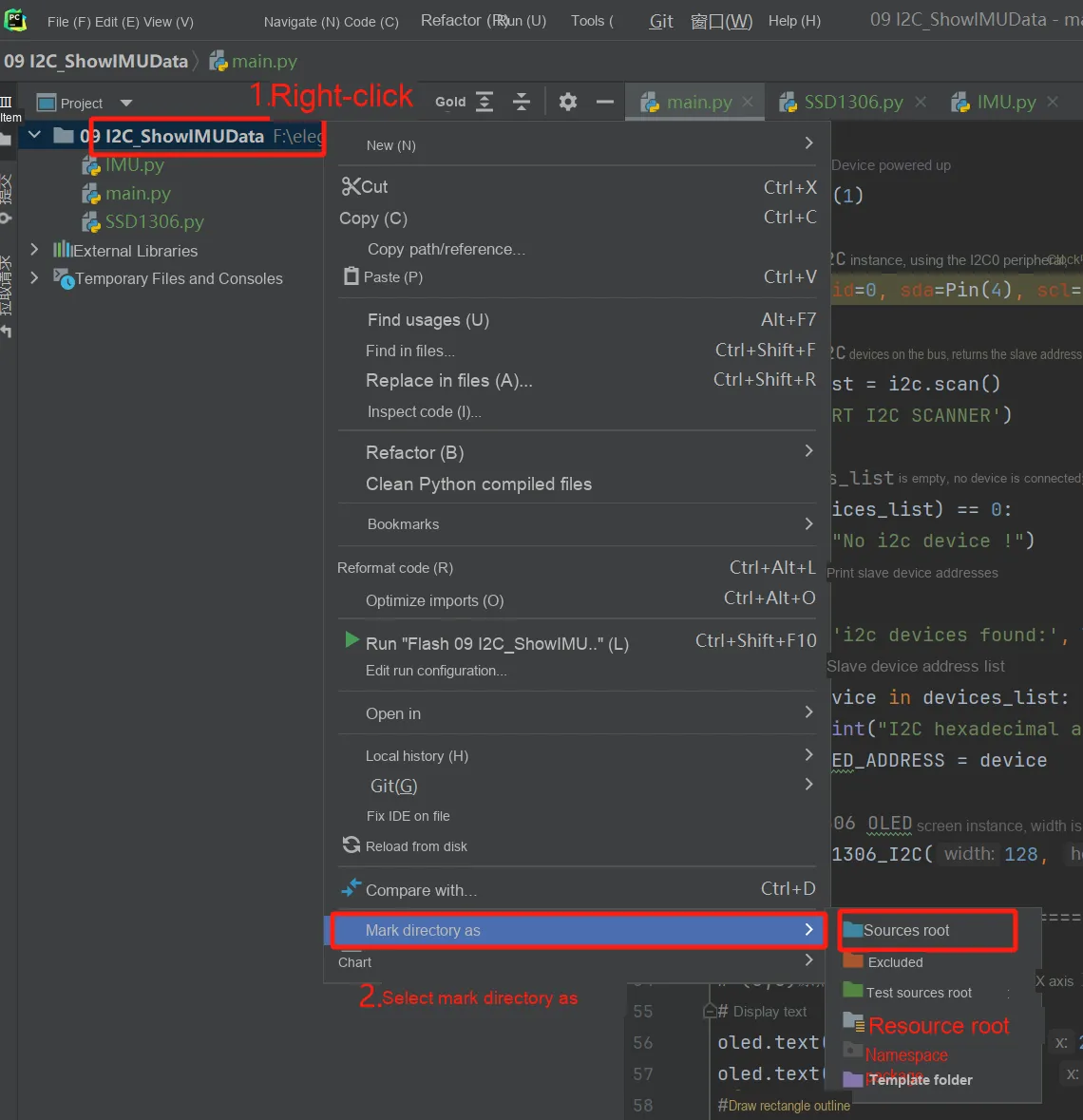
Then right-click the project folder and click - Run 'Flash 09 I2C_ShowlMU. ..':
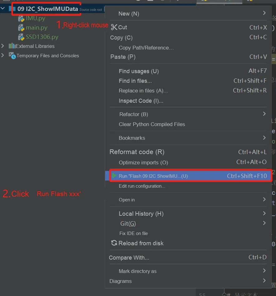
This way, the programming of three files can be completed in one go.
3.2.4 Experimental Phenomena
After the code is burned, open the terminal to connect to the Raspberry Pi Pico, and we can see the following output information:
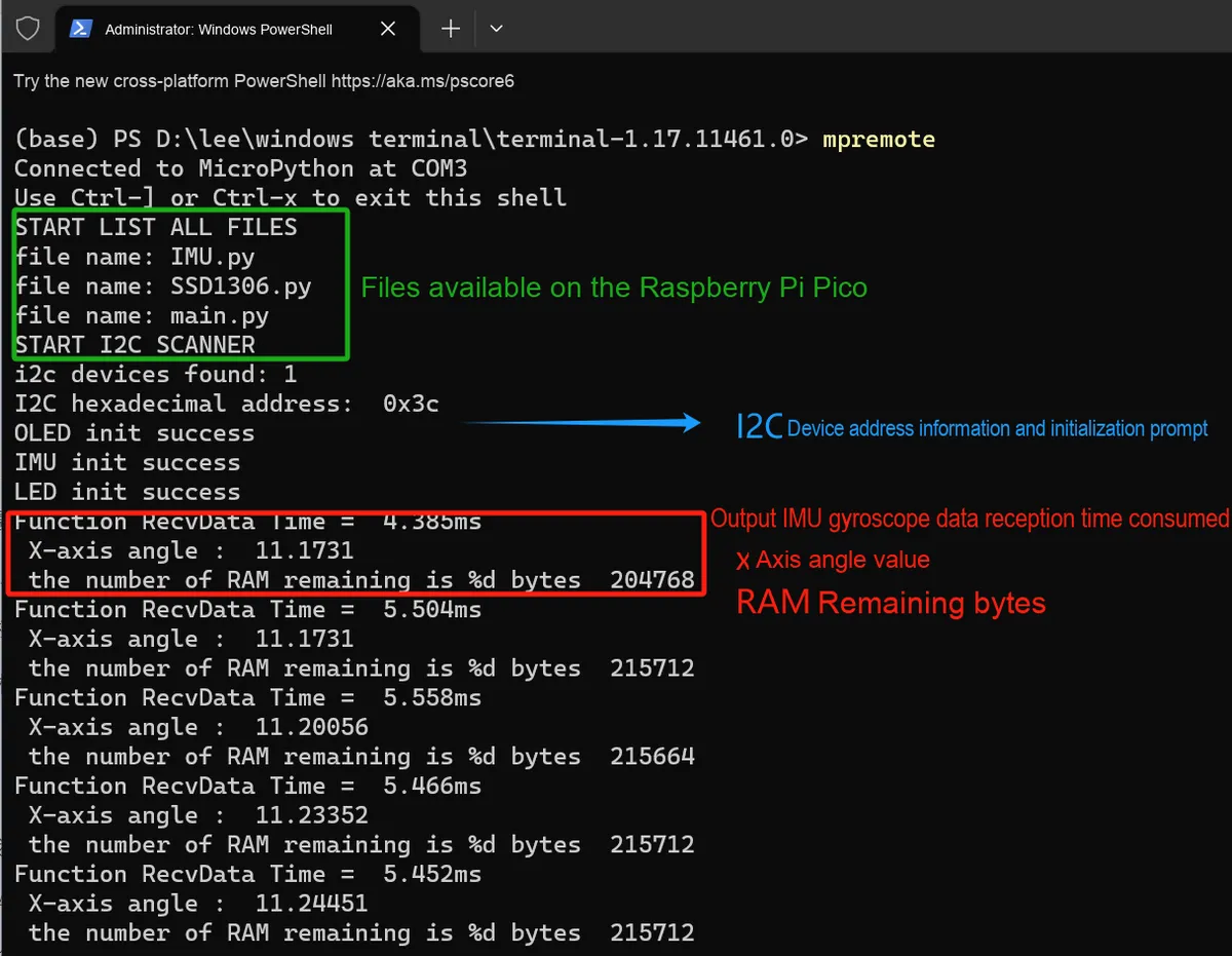
Next, we shake the entire development board:
3.2.1 Application Experiment.mp4 47.3 MB
We can observe the on-board LED of the Raspberry Pi Pico blinking, and as we rotate the gyroscope module along the X-axis, the X-axis angle data on the OLED screen keeps refreshing constantly:
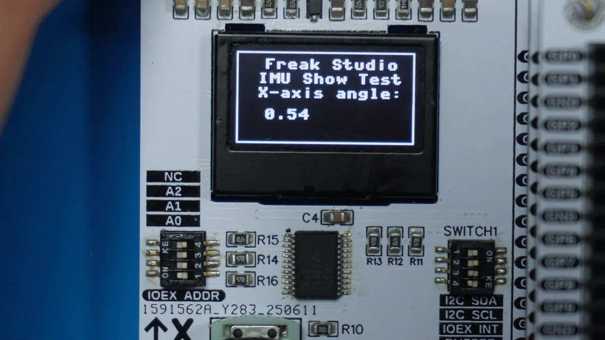
3.2.2 Application Experiment.mp4 35.3 MB
3.3 Extend GPIO Ports via I2C
3.3.1 Introduction to PCF8575 IO Expansion Chip
The PCF8575 is a 16-bit I2C-bus I/O expander chip that enables microcontrollers to communicate with external devices via the I2C bus, thereby controlling multiple GPIO pins on the chip for signal input or output, and is commonly used for controlling sensors, LED drivers and other digital devices.
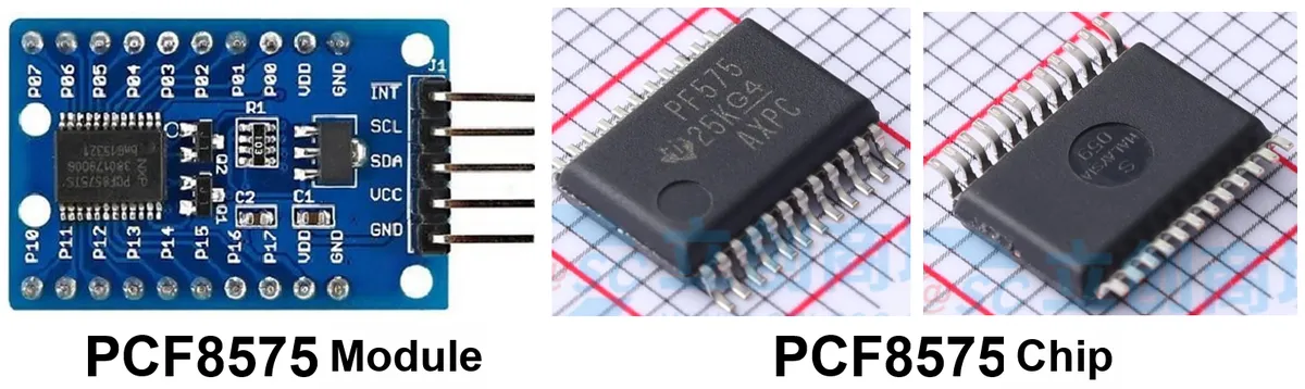
The pin naming and functions of the PCF8575 are shown as follows:
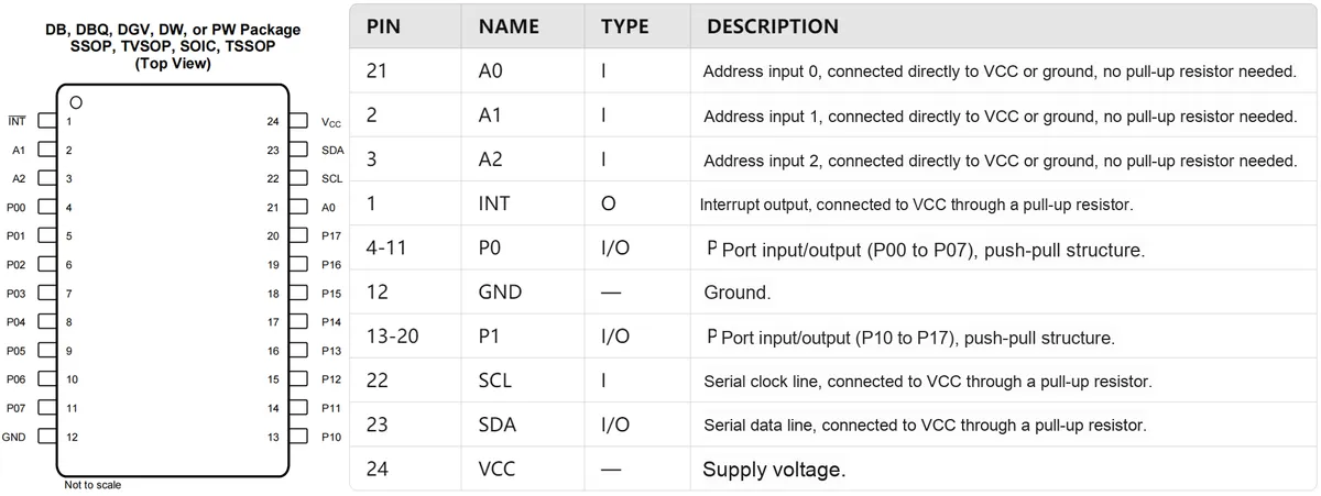
All of its ports are quasi-bidirectional input/output (I/O) ports (P07–P00 and P17–P10), each of which features high current driving capability and can directly drive LEDs. These ports have the following characteristics:
- It can be configured as input mode or output mode, and there is no need to use internal configuration or status registers; all operations need to directly read from and write to the I/O.
- Upon power-up, all I/O pins default to a high level and can be immediately used as inputs.
- Before using an I/O port as an input, it must first be set to a high level state.
The internal structure of the PCF8575 chip is shown as follows:
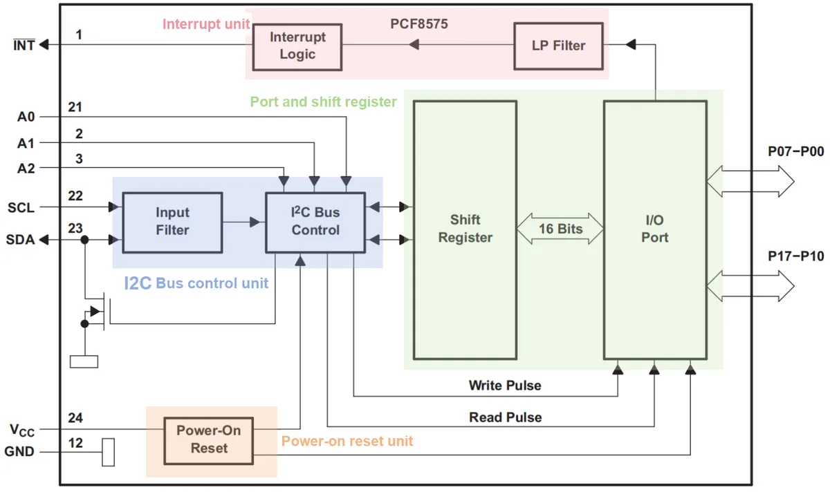
It includes the following parts:
- Power-on Reset Unit: When VCC is powered on, the internal power-on reset unit keeps the PCF8575 in a reset state until VCC reaches VPOR; at this point, the reset condition is released and the device initializes.
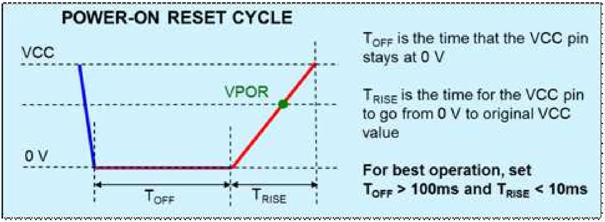
- I2C Bus Control Unit: It is used for I2C communication, and meanwhile controls the pins of the PCF8575 chip by manipulating the shift register according to the pin setting information sent from the outside; or sends the read pin level information to the outside via I2C. We can set the I2C address of the PCF8575 chip by configuring the high and low levels of the A2, A1 and A0 pins, and the relationship between the I2C address setting and the pin high/low levels is as follows:
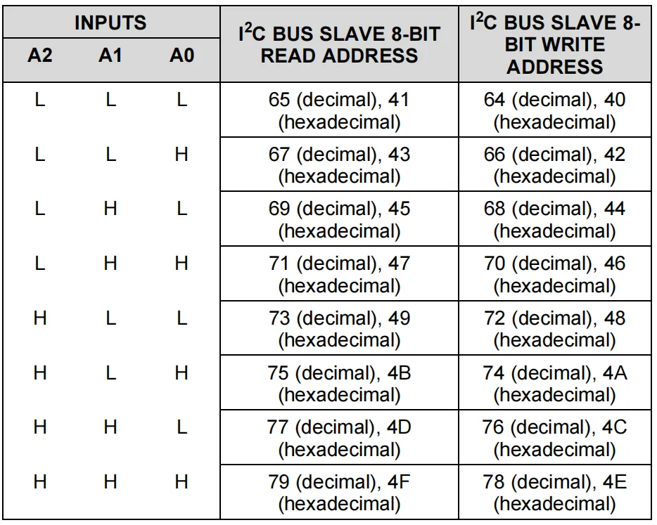
- Interrupt Unit: PCF8575 also provides an open-drain interrupt output (INT), which can be connected to the interrupt input of a microcontroller (an external pull-up resistor is required). When the port is set to input mode, any rising or falling edge will trigger an interrupt signal, which becomes valid after a certain period (approximately 4 microseconds). The interrupt can be reset by reading or writing port data.
- Ports and Shift Registers: There is a built-in 16-bit shift register inside, which is used to store the status of I/O ports; the shift register converts the serial data of pin configuration information transmitted by the I2C bus Control Unit into 16-bit parallel data, thereby controlling the high and low levels of the pins.
When we use a microcontroller to perform I2C communication with the PCF8575 chip, we first need to transmit the address bits, wait for the PCF8575 chip to send an acknowledge signal, and then transmit the data bits for the pin configuration of the PCF8575 chip:

When writing data bits for the pin configuration of the PCF8575 chip, special attention must be paid to the fact that the data transmitted to the PCF8575 each time must contain an even number of bytes: the first data byte in each pair corresponds to Port 0 (P07-P00), and the second data byte in each pair corresponds to Port 1 (P17-P10).

When writing data, the I2C data read/write bit is set to 0, while when reading data, the I2C data read/write bit is set to 1:
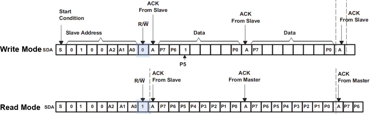
When we use the PCF8575 chip to expand the IO ports of a microcontroller, the commonly used connection structure is shown below:
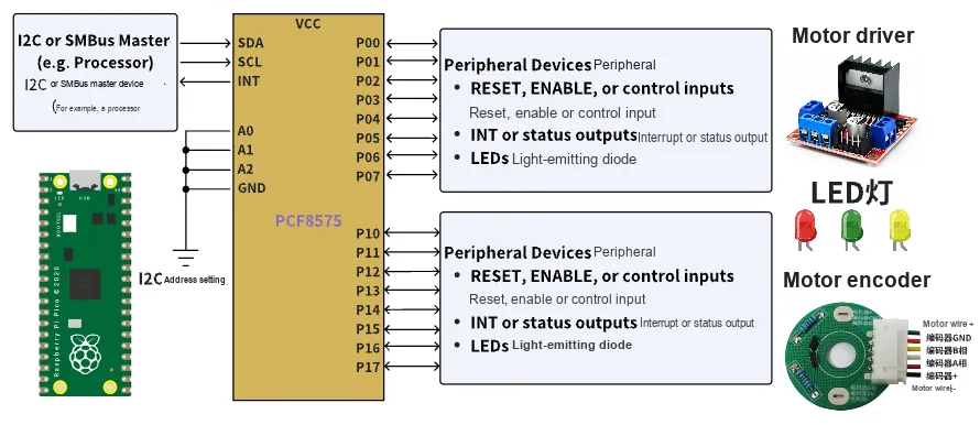
Connect the I2C interface of its chip to the I2C interface of the single-chip microcomputer, set the chip address by configuring the high and low levels of the three pins A0 to A2, and connect the port to digital devices such as sensors or LEDs.
The following is the schematic diagram of the reference application circuit provided in the datasheet:
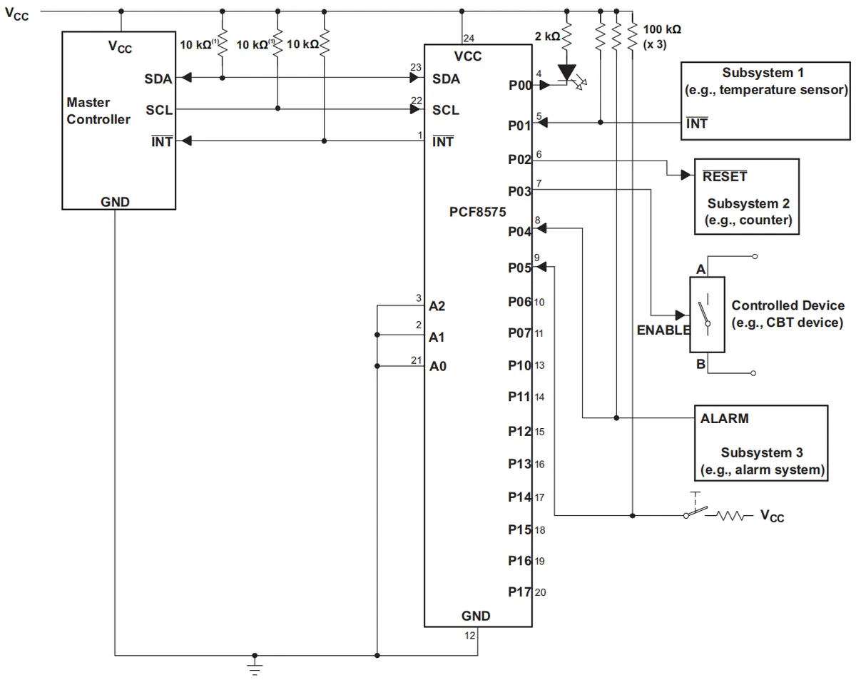
Among them, the SDA, SCL and INT pins require external pull-up resistors; A2, A1 and A0 are all connected to GND, and the I2C communication address is 0100000. Ports P0, P2 and P3 are configured as outputs, while ports P1, P4 and P5 are configured as inputs. Meanwhile, in the VCC power supply section of the PCF8575 chip, two capacitors need to be connected in parallel to filter the noise from the power supply (not shown in the figure).
The electrical parameters under its recommended operating conditions are shown in the following table:
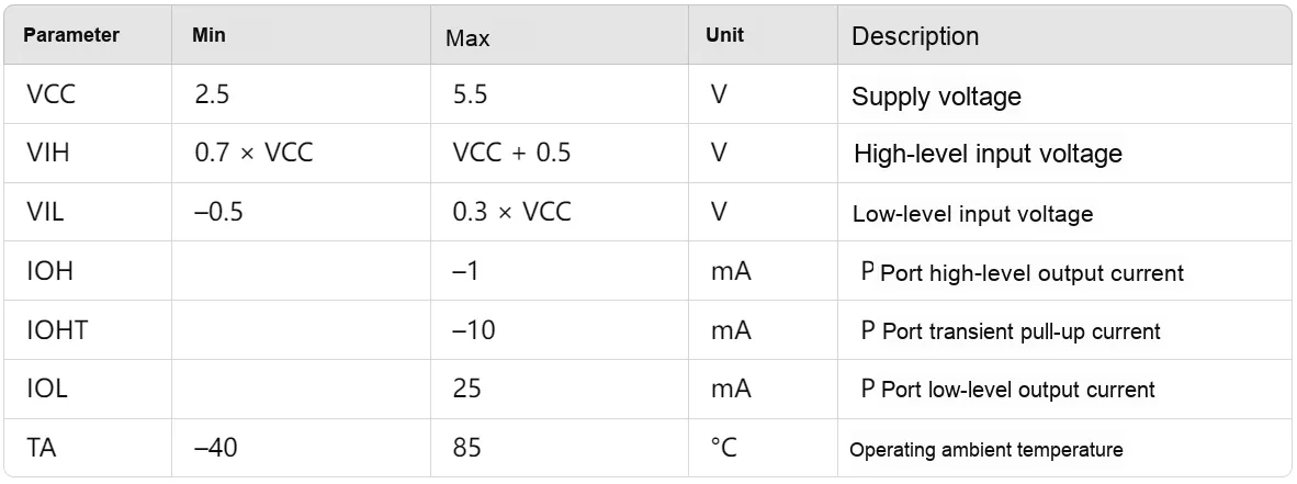
Here, it should be noted that when the port of the PCF8575 chip is used as an output, it can only sink current rather than source current at a high level:
IOH is the maximum output current (-1 mA), which refers to the maximum current that each port of the PCF8575 can provide when outputting a high level; this value is negative, indicating that the output port sinks current rather than sourcing current. IOHT is the maximum transient pull-up current (-10 mA), which describes the current of the port in a transient state, and can be understood as the maximum current that the port can withstand when switching from a low level to a high level.
IOL is the maximum low-level output current (25 mA), which refers to the maximum current that each pin of the PCF8575 can supply when the port outputs a low level (0V). It should be noted that the manual uses a positive value to represent IOL because it describes the current flowing into the chip, rather than directly using positive and negative signs for distinction.
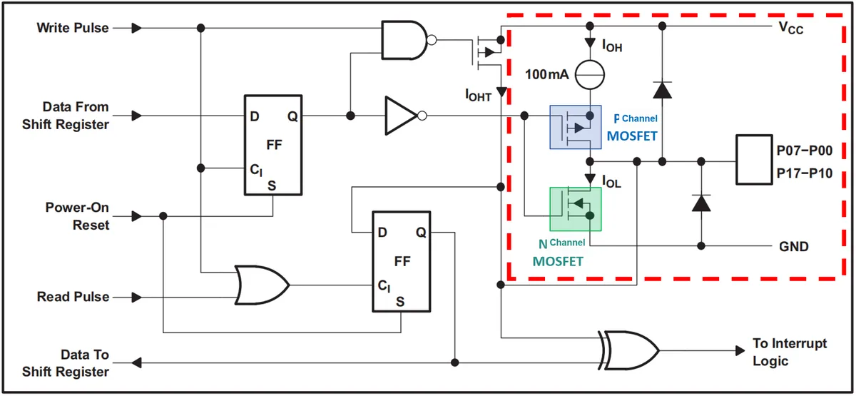
As can be seen from the figure above, the output section of the PCF8575 consists of two important MOSFETs (one P-channel MOSFET and one N-channel MOSFET), which are used to realize the level control of the port:
- High-level output: Current is supplied through a P-channel MOSFET to connect the output port to the power supply (VCC).
- Low-level output: The output port is connected to ground (GND) by sinking current via an N-channel MOSFET.
When the output port of the PCF8575 is at a low level, one end of the load is connected to VCC (for example, an LED load is connected to the power supply via a current-limiting resistor), and the other end of the load is connected to the output port of the PCF8575. Current flows from VCC through the load, then through the PCF8575 port and the N-channel MOSFET into GND, forming a closed loop. When the output port of the PCF8575 is at a low level, it mainly acts to "sink" current rather than source current.
When the output port of the PCF8575 outputs a high level, the P-channel MOSFET turns on, and the output port is directly connected to VCC. If a load is connected to the output port and grounded, current will flow from the port to the load; however, its driving capability for output high level is very limited (IOH ≈ -1 mA), meaning the ports of the PCF8575 cannot actively drive high-current loads.
The I2C interface of the PCF8575 chip supports a maximum clock frequency of 400 kHz. The following are the I²C communication parameters of this chip:
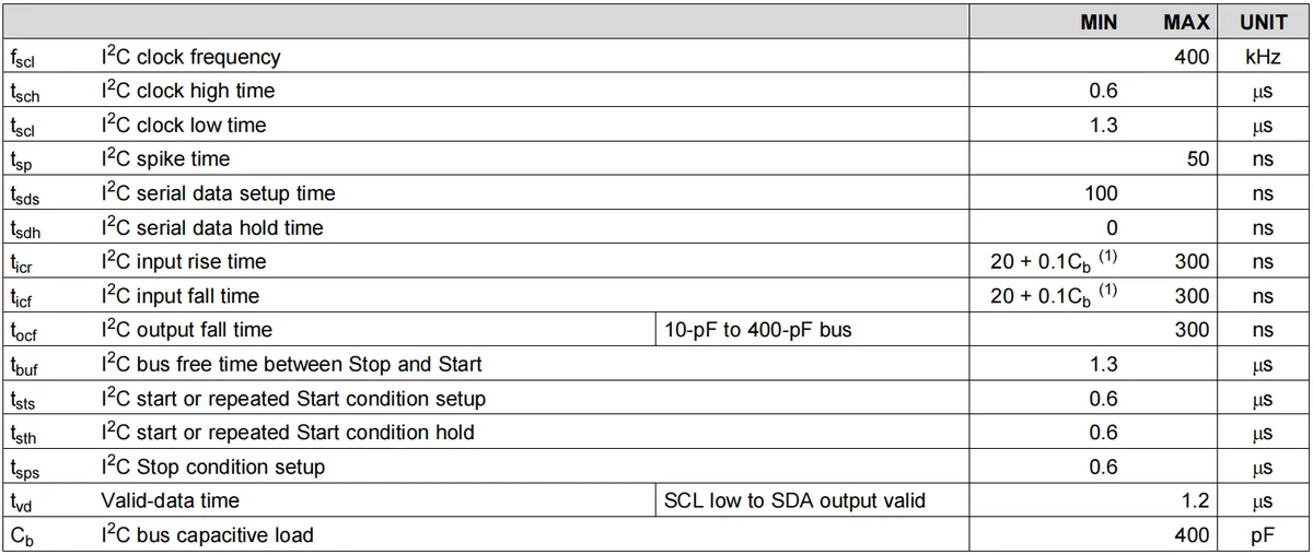
In I²C communication, when the master sends commands, the PCF8575 requires a certain period of time to process these commands (including reading and processing input signals, as well as generating output signals) and update the status of its I/O ports, with the delay specified in the table below:

If we use the PCF8575 chip in the device, attention should be paid during wiring that the power lines and signal lines should be routed on separate planes to avoid interference from the power supply to signals. The following is the PCB routing example provided in the datasheet:
3.3.2 Realization of Running Water Light with PCF8575
In the following experiment, we need to insert the Fengya No. 1 Board - Universal Compatible Expansion Board into the Fengya No. 1 Board - OLED Display and Interaction Expansion Board, and at the same time turn on the Fengya No. 1 Board - OLED Display and Interaction Expansion Board 's SWITCH1 DIP switch' s I2C_SDA and I2C_SCL options:
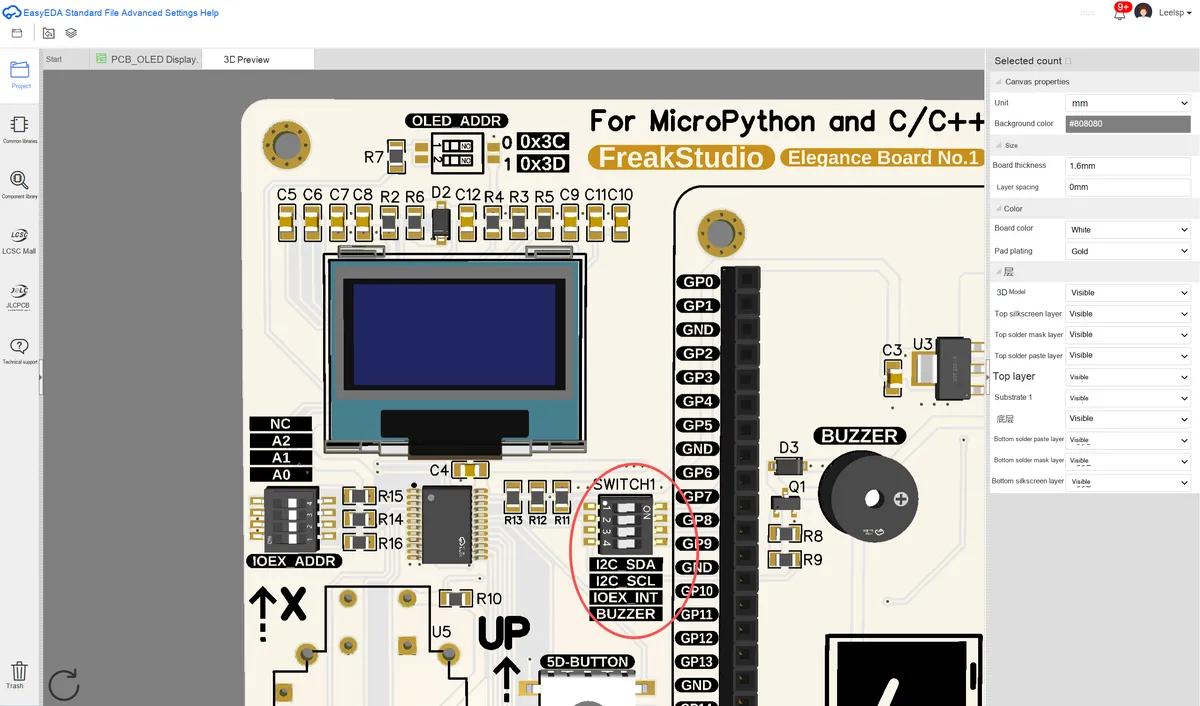
In addition, please select an address on the IOEX_ADDR DIP switch. In this example, we set the DIP switches of A2, A1 and A0 to the position 1, so the PCF8575 chip's I2C address is 0x27:
PCF8575 The connection pins between the chip and Raspberry Pi Pico are shown in the following table:
device | Module Signals / Pins | Pico pins (GPIO) |
PCF8575 chip | SDA | GP6 |
PCF8575 chip | SCL | GP7 |
In the following code, we control the PCF8575 chip via the I2C bus to cycle through and light up LEDs to achieve a flowing light effect. We use ports P0 to P7 as outputs to drive the LEDs; here, when connecting LEDs to the ports of the PCF8575, special attention should be paid to the power supply ranges of the two components:
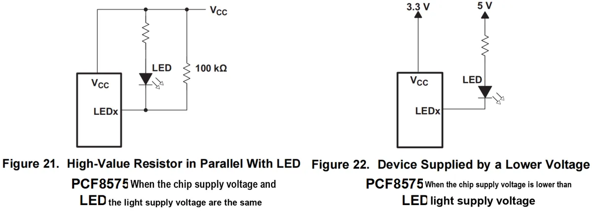
When the two are supplied with the same voltage, a 100 kΩ resistor needs to be connected in parallel to prevent additional power current consumption.
Considering that the PCF8575 chip has a weak high-level driving capability, our 8-bit flowing light module adopts a common-anode connection, so that the LED connected to the corresponding port will light up when the output port is at a low level:
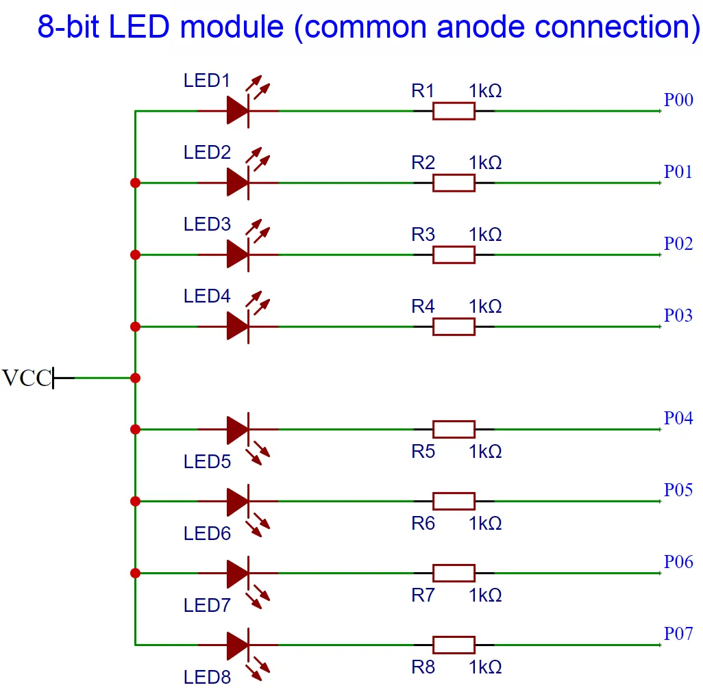
The following sample code can be found in the folder elegance-devkit v1\Demo\15 I2C_PCF8575_LED.
First, we customize a PCF8575 class to control the PCF8575 chip, and place this custom class in the pcf8575.py file. The sample code is shown below:
# Python env   : MicroPython v1.23.0
# -*- coding: utf-8 -*-
# @Time    : 2024/9/25 8:18 AM
# @Author  : Li Qingshui
# @File    : pcf8575.py
# @Description : Custom PCF8575 class, operated over the I2C bus
# Reference code: https://github.com/mcauser/micropython-pcf8575

# ======================================== Import Modules =========================================

# Import hardware-related modules
from machine import Pin, I2C

# ======================================== Global Variables ============================================

# ======================================== Functions ============================================

# ======================================== Custom Classes ============================================

class PCF8575:
    """
    PCF8575 class, used to operate the PCF8575 chip over the I2C bus and control 16 GPIO pins.

    This class encapsulates I2C communication with the PCF8575 chip and provides functions such as setting and reading the port state, operating individual pins, and toggling pins.
    In addition, it supports event triggering through an external interrupt pin and can register a callback function to handle the trigger event.

    Attributes:
        i2c (I2C): I2C instance used to communicate with the PCF8575.
        address (int): I2C device address, default value 0x20.
        interrupt_pin (Pin): Optional interrupt pin instance used to trigger an external interrupt.
        callback (callable): Optional callback function, called when the interrupt is triggered.

    Methods:
        __init__(self, i2c, address=0x20, interrupt_pin=None, callback=None):
            Initialize the PCF8575 class instance.

        check(self):
            Check whether the PCF8575 is on the I2C bus.

        port(self):
            Get the current state of the port.

        port(self, value):
            Set the state of the port.

        pin(self, pin, value=None):
            Get or set the state of the specified pin.

        toggle(self, pin):
            Toggle the high/low level of the specified pin.

        _validate_pin(self, pin):
            Verify the validity of the pin number.

        _read(self):
            Read the port state from I2C.

        _write(self):
            Write the port state to I2C.

        _interrupt_handler(self, pin):
            Interrupt handler function, calls the callback function when the external interrupt pin is triggered.
    """

    def __init__(self, i2c: I2C, address: int = 0x20, interrupt_pin: Pin = None, callback: callable = None):
        """
        Initialize the PCF8575 class instance.

        This method initializes the I2C bus, sets the device address, initializes the port state, and configures the interrupt pin and callback function (if provided).

        Args:
            i2c (I2C): I2C instance used to communicate with the PCF8575.
            address (int): I2C address, default value 0x20, indicating the device address.
            interrupt_pin (Pin): Interrupt pin instance used to trigger an external interrupt. When the state of the interrupt pin changes, the interrupt is triggered and the callback function is called.
            callback (callable): Optional callback function, called when the external interrupt pin changes.
        """
        # Save the I2C instance
        self._i2c = i2c
        # Save the I2C address
        self._address = address
        # Initialize port data as a 2-byte bytearray
        self._port = bytearray(2)

        # Save the interrupt pin and callback function
        self.interrupt_pin = interrupt_pin
        self.callback = callback

        # If an interrupt pin is provided, set the pin as input with internal pull-up and add a falling-edge interrupt handler
        if self.interrupt_pin:
            self.interrupt_pin.init(Pin.IN, Pin.PULL_UP)
            self.interrupt_pin.irq(trigger=Pin.IRQ_FALLING, handler=self._interrupt_handler)

    def check(self) -> bool:
        """
        Check whether the PCF8575 is on the I2C bus.

        Args:
            None

        Returns:
            bool: Returns True if the device is present; otherwise, raises an OSError exception.

        Raises:
            OSError: If the device is not found on the I2C bus.
        """
        # Check whether the device is present
        if self._i2c.scan().count(self._address) == 0:
            # Raise an error
            raise OSError(f"PCF8575 not found at I2C address {self._address:#x}")
        return True

    @property
    def port(self) -> int:
        """
        Get the current state of the port.

        Args:
            None

        Returns:
            int: Integer value of the port state.
        """
        # Read the current port state
        self._read()
        # Return the combined port value
        return self._port[0] | (self._port[1] << 8)

    @port.setter
    def port(self, value: int) -> None:
        """
        Set the state of the port.

        Args:
            value (int): Port state to set (sets all 16 pins at once).

        Returns:
            None
        """
        # Set the state of the lower eight pins
        self._port[0] = value & 0xFF
        # Set the state of the upper eight pins
        self._port[1] = (value >> 8) & 0xFF
        # Write the new port state
        self._write()

    def pin(self, pin: int, value: bool = None) -> int:
        """
        Get or set the state of the specified pin.

        Args:
            pin (int): Pin number (0-7 or 10-17).
            value (bool): Set the pin state (True for high, False for low). If None, get the pin state.

        Returns:
            int: If `value` is None, returns the current state of the pin; otherwise, returns None.
        """
        # Validate the pin number
        pin = self._validate_pin(pin)

        # If value is None, return the current pin state
        if value is None:
            # Read the port state
            self._read()
            # Return the pin state
            # pin // 8 computes the byte index, pin % 8 computes the bit position of the pin within the byte
            # Use & 1 to get the high/low level of the pin
            return (self._port[pin // 8] >> (pin % 8)) & 1

        # Set the pin state
        if value:
            # Set the pin high
            self._port[pin // 8] |= 1 << (pin % 8)
        else:
            # Set the pin low
            self._port[pin // 8] &= ~(1 << (pin % 8))
            # Write the new port state
        self._write()

    def toggle(self, pin: int) -> None:
        """
        Toggle the high/low level of the specified pin.

        Args:
            pin (int): Pin number (0-7 or 10-17).

        Returns:
            None
        """
        # Validate the pin number
        pin = self._validate_pin(pin)
        # Toggle the pin state
        self._port[pin // 8] ^= 1 << (pin % 8)
        # Write the new port state
        self._write()

    def _validate_pin(self, pin: int) -> int:
        """
        Verify the validity of the pin number.

        Args:
            pin (int): Pin number.

        Returns:
            int: Valid pin number.

        Raises:
            ValueError: If the pin number is invalid.
        """

        # Valid pin range is 0..7 and 10-17 (offset to 8-15)
        # First digit: port (0-1)
        # Second digit: IO (0-7)
        if not 0 <= pin <= 7 and not 10 <= pin <= 17:
            # Raise an error
            raise ValueError(f"Invalid pin {pin}. Use 0-7 or 10-17.")

        # Adjust the pin number: subtract 2 when the pin number is greater than or equal to 10
        if pin >= 10:
            pin -= 2

        # Return the valid pin number
        return pin

    def _read(self) -> None:
        """
        Read the port state from I2C.

        Args:
            None

        Returns:
            None
        """
        # Read data from I2C into the port
        self._i2c.readfrom_into(self._address, self._port)

    def _write(self) -> None:
        """
        Write the port state to I2C.

        Args:
            None

        Returns:
            None
        """
        # Write the port data to I2C
        self._i2c.writeto(self._address, self._port)

    def _interrupt_handler(self, pin: Pin) -> None:
        """
        Interrupt handler function, calls the callback function when the external interrupt pin is triggered.

        Args:
            pin (Pin): The pin that triggered the interrupt.

        Returns:
            None
        """
        if self.callback:
            self.callback(pin)

# ======================================== Initialization ==========================================

# ========================================  Main Program  ===========================================
In the custom PCF8575 class defined above, we have provided the following methods:
- Initialization: In the
initmethod, store the I2C instance and device address, initialize the port status, and configure the interrupt pin and callback function - Device check:
The checkmethod is used to detect whether the PCF8575 is present on the I2C bus. If the device is not found, anOSError will be thrown. - Port Status Management:
the portattribute allows users to get or set the status of 16 pins at once, and actual I2C read and write operations are performed by calling the_readand_writemethods - Pin Operations:
pinmethod is used to get or set the state of the specified pin, and thetogglemethod is used to flip the state of the specified pin - Interrupt Handling: If an interrupt pin is provided, set it as an input and register the interrupt handling function; when an interrupt occurs, the user-defined callback function will be invoked.
- Verification method:
_validate_pinThis method verifies the validity of the pin number, which must be in the range of 0~7 or 10~17.
Here, we use the @property attribute decorator to convert the port method into an attribute access approach, so that the method can be used just like accessing an attribute; meanwhile, we define the port setter method to set the status of the port. For knowledge points related to the @property attribute decorator, you can refer to the following article:
The basic principle of the method for configuring pins or reading pin states as mentioned above is as follows:
- When reading the pin status, first call the
_readmethod to read the current port status from I2C, then calculate its position in the port data according to the pin number, and extract and return its status - When setting the pin state, update the status of the corresponding byte according to the input value (high or low), then call the
_writemethod to write the new status to the I2C peripheral.
In the main program, we perform the following operations:
- Create an I2C instance, and configure the SDA and SCL pins as well as the clock frequency
- Scan the I2C bus to find connected devices and output the addresses of the found devices
- Create
PCF8575class instance and pass in the I2C instance - In an infinite loop, turn on each LED in sequence, and delay for 0.2 seconds after each is lit
- After each activation, read and print the lower 8 bits of the PCF8575 port status and output them in binary form
- After all LEDs are lit, set all port states to high, delay for 0.2 seconds, and then repeat the cycle.
The sample code is shown below:
# Python env   : MicroPython v1.23.0
# -*- coding: utf-8 -*-
# @Time    : 2024/9/25 AM 8:31
# @Author  : Li Qingshui
# @File    : main.py
# @Description : I2C class experiment, using the PCF8575 chip to control a running LED display

# ======================================== Import Modules =========================================

# Hardware-related modules
from machine import I2C, Pin
# Time-related modules
import time
# Import the custom PCF8575 class
from pcf8575 import PCF8575

# ======================================== Global Variables ============================================

# PCF8575 chip address
PCF8575_ADDRESS: int = 0
# Number of LEDs
LED_COUNT: int = 8

# ======================================== Functions ============================================

# ======================================== Custom Classes ============================================

# ======================================== Initialization ==========================================

# Power-on delay of 3 s
time.sleep(3)
# Print debug message
print("FreakStudio: control LED using the PCF8575 I/O expander with I2C")

# Create a hardware I2C instance using the I2C1 peripheral, clock frequency 400KHz, SDA pin 6, SCL pin 7
i2c: I2C = I2C(id=1, sda=Pin(6), scl=Pin(7), freq=400000)

# Start scanning for devices on the I2C bus and return a list of slave addresses
devices_list: list[int] = i2c.scan()
print('START I2C SCANNER')

# If devices_list is empty, no device is connected to the I2C bus
if len(devices_list) == 0:
    print("No i2c device !")
# If not empty, print the slave device addresses
else:
    print('i2c devices found:', len(devices_list))
    # Iterate over the slave device address list
    for device in devices_list:
        # Check whether the device address is the PCF8575 address
        if device >= 0x20 and device <= 0x27:
            print("I2C hexadecimal address: ", hex(device))
            # Assume the first device found is the PCF8575
            PCF8575_ADDRESS = device

# Create a PCF8575 class instance
pcf8575 = PCF8575(i2c, PCF8575_ADDRESS)

# ========================================  Main Program  ===========================================

# Run in a loop
while True:
    # Set the port state to 1 to turn off all the LEDs
    pcf8575.port = 0x00FF
    # Delay 0.5 seconds
    time.sleep(0.5)

    # Control the running LED effect
    for i in range(LED_COUNT):
        # Set the i-th pin low to light the corresponding LED
        pcf8575.pin(i, False)
        # Delay 0.1 seconds
        time.sleep(0.2)

        # Read the lower eight bits of the port state
        state: int = pcf8575.port & 0xFF
        # Display the state in binary form
        print("Lower 8 bits state: {:08b}".format(state))

    # Delay 0.5 seconds
    time.sleep(0.5)
After burning the code and establishing a remote connection, the terminal displays the following:
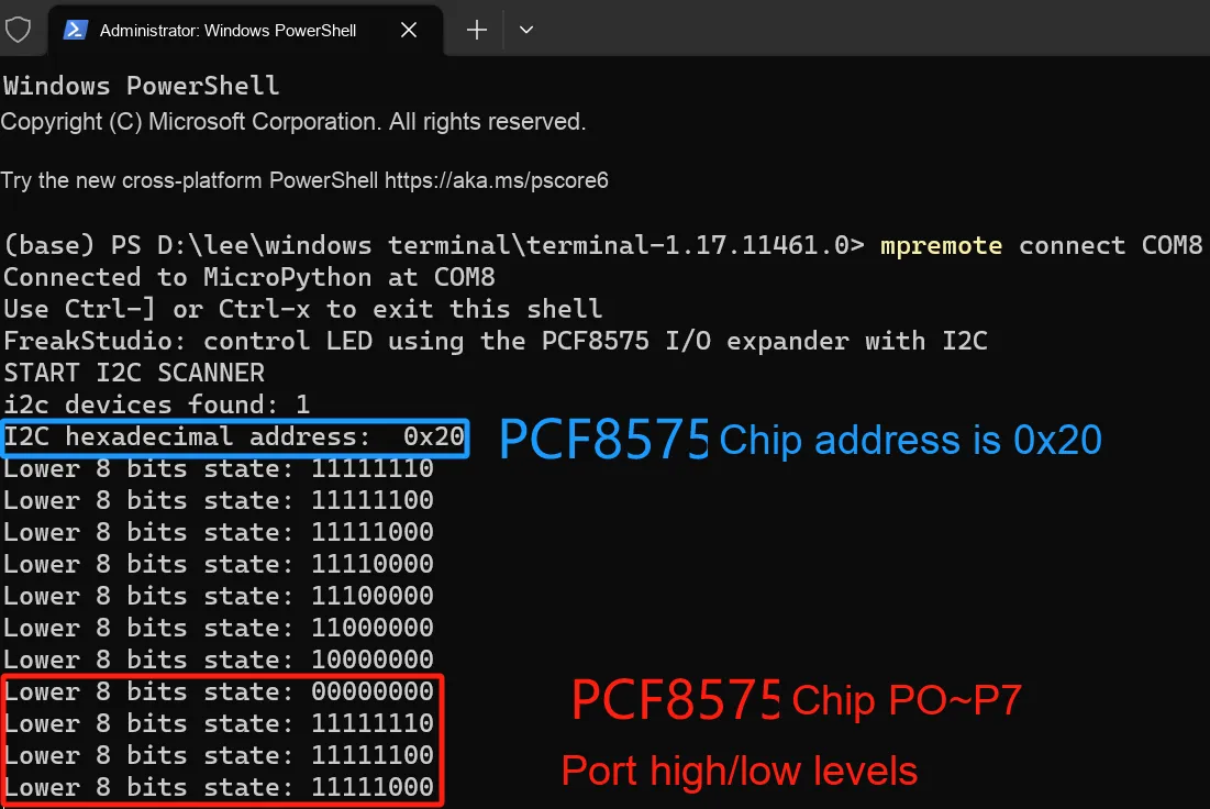
As you can see, the 8 LED lights light up in a sequential loop:
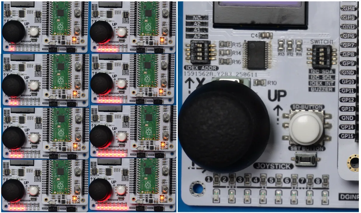
3.3.1 Application Experiment.mp4 31.4 MB
3.3.3 Reading 5-Direction Keys with PCF8575
In the following experiment, we need to insert the Fengya No. 1 Board - General Compatible Expansion Board into the Fengya No. 1 Board - OLED Display and Interaction Expansion Board, and at the same time turn on the Fengya No. 1 Board - OLED Display and Interaction Expansion Board 's SWITCH1 dip switch' s I2C_SDA, I2C_SCL and IOEX_INT options:
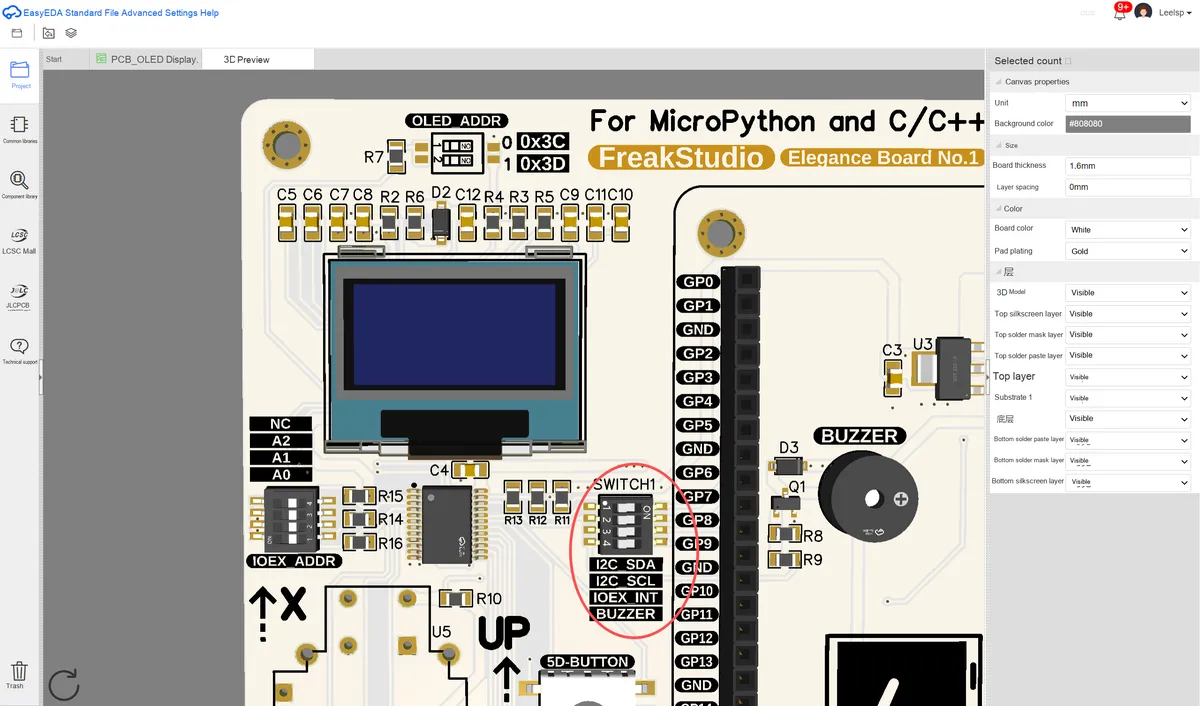
In addition, please select an address on the IOEX_ADDR DIP switch. In this example, we set the DIP switches of A2, A1 and A0 to the 1 position, so the PCF8575 chip's I2C address is 0x27:
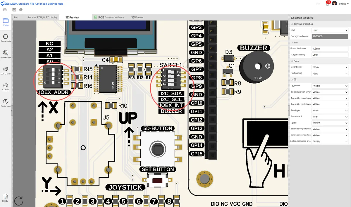
PCF8575 The pins for connecting the chip to the Raspberry Pi Pico are shown in the following table:
device | Module Signals / Pins | Pico pins (GPIO) |
PCF8575 chip | SDA | GP6 |
PCF8575 chip | SCL | GP7 |
PCF8575 chip | INT | GP8 |
In the following code, we implement a simple menu framework on an OLED screen. Using a Raspberry Pi Pico, we read the status of the 5-way navigation key via the PCF8575 chip, and display an interactive menu on the OLED screen. Users can navigate the menu via the keys, view and set parameters, control the LED, and perform other functions.
First, let's introduce our menu framework. Here we have customized a SimpleOLEDMenu class and a MenuNode class to implement the menu effect on the OLED screen. The sample code is as follows:
# Python env   : MicroPython v1.23.0
# -*- coding: utf-8 -*-
# @Time    : 2024/9/26 PM 5:17
# @Author  : Li Qingshui
# @File    : menu.py
# @Description : Simple OLED menu display library

# ======================================== Import Modules =========================================

# Time-related modules
import time

# ======================================== Global Variables ============================================

# ======================================== Functions ============================================

# ======================================== Custom Classes ============================================

class MenuNode:
    """
    The MenuNode class represents each node in the menu, containing the menu name, callback functions, and submenus.

    This class encapsulates the basic information of a menu node, including its name, the callback functions for entering and exiting the menu, and submenu management.
    Each menu node can have multiple submenus, and recursive lookup and management are supported.

    Attributes:
        name (str): Menu name, uniquely identifying a menu node.
        next (MenuNode): The next menu node, currently unused.
        sub_menu (list): Stores all submenu nodes of this menu.
        enter_callback (callable): Callback function called when entering this menu.
        exit_callback (callable): Callback function called when exiting this menu.

    Methods:
        __init__(self, name:str, enter_callback : callable=None, exit_callback : callable=None):
            Initialize a MenuNode instance and set the menu name and callback functions.
    """
    def __init__(self, name:str, enter_callback : callable=None, exit_callback : callable=None):
        self.name = name
        self.next = None
        self.sub_menu = []
        self.enter_callback = enter_callback
        self.exit_callback = exit_callback

class SimpleOLEDMenu:
    """
    The SimpleOLEDMenu class manages and displays a menu system on an OLED screen.

    This class provides a simple menu system that can display multi-level menus on an OLED display. The user can select menu items up and down and enter submenus,
    and can also return to the parent menu. The menu supports callback functions, which trigger specific actions when entering and exiting menus.

    Attributes:
        oled (OLED): OLED display object used to display the menu.
        name (str): Menu name, used to identify the menu.
        x (int): Starting X coordinate of the menu.
        y (int): Starting Y coordinate of the menu.
        width (int): Width of the menu.
        height (int): Height of the menu.
        head (MenuNode): Root menu node, representing the starting point of the entire menu.
        selected_index (int): Index of the currently selected menu item.
        menu_stack (List[MenuNode]): Stack storing the menu hierarchy.
        scroll_offset (int): Scroll offset of the current menu.

    Methods:
        __init__(self, oled: OLED, name: str, pos_x: int, pos_y: int, width: int, height: int) -> None:
            Initialize a SimpleOLEDMenu instance and set the menu-related parameters.

        add_menu(self, name: str, parent_name: str = None, enter_callback: Callable = None, exit_callback: Callable = None) -> None:
            Add a new menu item to the specified parent menu.

        _find_node(self, current: MenuNode, name: str) -> Union[MenuNode, None]:
            Recursively check whether a menu item with the specified name exists in the menu.

        delete_menu(self, name: str) -> None:
            Delete the menu item with the specified name and update the display.

        display_menu(self) -> None:
            Display the current menu, with support for scrolling and the selected state.

        select_down(self) -> None:
            Select the next menu item down and update the display.

        select_up(self) -> None:
            Select the previous menu item up and update the display.

        select_current(self) -> None:
            Select the current menu item and enter its submenu.

        select_back(self) -> None:
            Return to the parent menu.

        show_message(self, message: str) -> None:
            Display a prompt message, center-aligned with an outer rectangular frame.

        get_current_menu_name(self) -> Union[str, None]:
            Get the name of the currently selected menu item.
    """
    def __init__(self, oled, name: str, pos_x: int, pos_y: int, width: int, height: int) -> None:
        """
        Initialize a SimpleOLEDMenu instance.

        Args:
            oled (OLED): OLED display object.
            name (str): Menu name.
            pos_x (int): Starting X coordinate of the menu.
            pos_y (int): Starting Y coordinate of the menu.
            width (int): Menu width.
            height (int): Menu height.

        Returns:
            None
        """
        # Initialize the OLED display object
        self.oled = oled
        # Set the menu name
        self.name = name
        # Set the starting X coordinate of the menu
        self.x = pos_x
        # Set the starting Y coordinate of the menu
        self.y = pos_y
        # Set the menu width
        self.width = width
        # Set the menu height
        self.height = height
        # Create the root menu node
        self.head = MenuNode(name)
        # Index of the currently selected menu item, initially 0
        self.selected_index = 0
        # Menu hierarchy stack, used to manage the menu levels
        self.menu_stack = []
        # Current scroll offset, initialized to 0
        self.scroll_offset = 0

    def add_menu(self, name: str, parent_name: str = None, enter_callback=None, exit_callback=None) -> None:
        """
        Add a new menu item.

        Args:
            name (str): Menu item name.
            parent_name (str, optional): Parent menu name. Defaults to None, which means adding to the root menu.
            enter_callback (callable, optional): Callback function called when entering the menu.
            exit_callback (callable, optional): Callback function called when exiting the menu.

        Returns:
            None

        Raises:
            ValueError: If the menu name is too long or the parent menu is not found.
        """
        # Check whether the menu name exceeds the display range
        if len(name) * 8 > self.width:
            # Raise an error
            raise ValueError("Directory name is too long")

        # Check whether a duplicate name exists
        if self._find_node(self.head, name):
            # Raise an error
            raise ValueError("Menu name already exists")

        # Create a new menu node
        new_node = MenuNode(name, enter_callback, exit_callback)

        # If there is no parent node, add to the root menu
        if parent_name is None:
            # Add to the root menu
            self.head.sub_menu.append(new_node)
        else:
            # Find the parent node and add the new menu node as a submenu
            parent_node = self._find_node(self.head, parent_name)
            if parent_node:
                # Add the submenu
                parent_node.sub_menu.append(new_node)
            # If the parent node is not found, raise an error
            else:
                # Raise an error
                raise ValueError("Parent menu not found, please check the name")

    def _find_node(self, current, name: str) -> 'MenuNode':
        """
        Recursively find a menu node.

        Args:
            current (MenuNode): The current node.
            name (str): The name of the menu to find.

        Returns:
            MenuNode: The menu node found, or None if not found.
        """
        # If the current node is empty, return None
        if current is None:
            return None

        # If the current node's name matches, return the current node
        if current.name == name:
            return current

        # Iterate over the submenus of the current node
        for sub in current.sub_menu:
            # Recursively search the submenu
            found = self._find_node(sub, name)
            if found:
                # Node found, return it
                return found

        # Node not found, return None
        return None

    def delete_menu(self, name: str) -> None:
        """
        Delete the menu item with the specified name.

        Args:
            name (str): Menu item name.

        Returns:
            None

        Raises:
            ValueError: If the menu item does not exist.
        """
        # Delete the menu with the specified name from the root menu
        self.head.sub_menu = [node for node in self.head.sub_menu if node.name != name]

        # Check whether all menu items in the current submenu have been deleted
        if len(self.head.sub_menu) == 0:
            # Exit to the previous menu level
            self.select_back()

        # Update the display
        self.display_menu()

    def display_menu(self) -> None:
        """
        Display the current menu.

        Args:
            None

        Returns:
            None
        """

        # Clear the OLED display
        self.oled.fill(0)
        # Initialize the Y-axis offset
        y_offset = self.y

        # Iterate over and display the current menu items
        for index, item in enumerate(self.head.sub_menu):
            # If the current menu item is selected
            if index == self.selected_index:
                # Display the selected item in inverted colors
                self.oled.fill_rect(self.x, y_offset, self.width, 8, 1)
                # Set the font color of the selected item to black
                self.oled.text(item.name, self.x, y_offset, 0)
            else:
                # Set the font color of unselected items to white
                self.oled.text(item.name, self.x, y_offset, 1)

            # Update the Y-axis offset, taking the scroll offset into account
            y_offset += 8

        # If the submenu items exceed the screen display height, show the scroll offset
        if len(self.head.sub_menu) > self.height // 8:
            # Clear the previous menu area
            self.oled.fill_rect(self.x, self.y, self.width, self.height, 0)
            # Calculate the number of menu items that can be displayed
            max_display = min(len(self.head.sub_menu) - self.scroll_offset, self.height // 8)
            # Display the visible menu items
            for i in range(max_display):
                # Draw the menu items within the visible range
                if i + self.scroll_offset == self.selected_index:
                    # Display the selected item in inverted colors
                    self.oled.fill_rect(self.x, self.y + i * 8, self.width, 8, 1)
                    # Black font
                    self.oled.text(self.head.sub_menu[i + self.scroll_offset].name, self.x, self.y + i * 8, 0)
                else:
                    # White font
                    self.oled.text(self.head.sub_menu[i + self.scroll_offset].name, self.x, self.y + i * 8, 1)

        # Update the OLED display
        self.oled.show()

    def select_down(self) -> None:
        """
        Select the next menu item (down).

        Args:
            None

        Returns:
            None
        """
        # Increment the selected index
        self.selected_index += 1

        # If beyond the menu range, reset to 0
        if self.selected_index >= len(self.head.sub_menu):
            self.selected_index = 0
            # Reset the scroll offset to show the first page
            self.scroll_offset = 0

        # Scroll the display if the selected item is out of the visible range
        if self.selected_index - self.scroll_offset >= self.height // 8:
            # Scroll down
            self.scroll_offset += 1

        # Update the display
        self.display_menu()

    def select_up(self) -> None:
        """
        Select the previous menu item (up).

        Args:
            None

        Returns:
            None
        """
        # Decrement the selected index
        self.selected_index -= 1

        # If less than 0, reset to the last item
        if self.selected_index < 0:
            self.selected_index = len(self.head.sub_menu) - 1
            # Scroll to the last page
            self.scroll_offset = max(0, len(self.head.sub_menu) - (self.height // 8))
        # Scroll the display if the selected item is above the top of the visible range
        elif self.selected_index < self.scroll_offset:
            # Scroll up
            self.scroll_offset -= 1

        # Update the display
        self.display_menu()

    def select_current(self) -> None:
        """
        Select the current menu item and enter its submenu.

        Args:
            None

        Returns:
            None
        """
        # Get the currently selected menu
        current_menu = self.head.sub_menu[self.selected_index] if self.selected_index < len(self.head.sub_menu) else None

        # If the current menu exists
        if current_menu:
            # Call the enter callback
            if current_menu.enter_callback:
                current_menu.enter_callback()

            # If the current menu has a submenu, enter the submenu
            if current_menu.sub_menu:
                # Push the current menu onto the stack
                self.menu_stack.append(self.head)
                # Set the current menu to the submenu
                self.head = current_menu
                # Reset the selected index
                self.selected_index = 0
                # Reset the scroll offset
                self.scroll_offset = 0
                # Update the display
                self.display_menu()

    def select_back(self) -> None:
        """
        Return to the parent menu.

        Args:
            None

        Returns:
            None
        """
        # If the menu stack is not empty
        if self.menu_stack:
            # Call the exit callback
            if self.head.exit_callback:
                self.head.exit_callback()
            # Pop the parent menu
            self.head = self.menu_stack.pop()
            # Call the enter callback
            if self.head.enter_callback:
                self.head.enter_callback()
            # Reset the selected index
            self.selected_index = 0
            # Update the display
            self.display_menu()

    def show_message(self, message: str) -> None:
        """
        Display a prompt message.

        Args:
            message (str): The prompt message to display.

        Returns:
            None

        Raises:
            Exception: If the message length exceeds 13 characters.
        """
        # Check the message length and raise an exception if it is too long
        if len(message) > 13:
            raise Exception("Message too long")

        # Get the width and height of the OLED display
        oled_width = self.oled.width
        oled_height = self.oled.height

        # Rectangle parameters
        rect_width  = 120
        rect_height = 32
        x = (oled_width - rect_width) // 2
        y = (oled_height - rect_height) // 2

        # Clear the display
        self.oled.fill(0)

        # First display the existing menu
        self.display_menu()

        # Draw the outer rectangle
        self.oled.rect(x, y, rect_width, rect_height, 1)
        # Fill the inner rectangle
        self.oled.fill_rect(x + 5, y + 5, rect_width - 10, rect_height - 10, 1)

        # Display the prompt message
        message_x = int(x + (rect_width - len(message) * 8) // 2)
        message_y = int(y + (rect_height - 8) // 2)
        self.oled.text(message, message_x, message_y, 0)

        # Refresh the display
        self.oled.show()

        # Wait for 1 second
        time.sleep(1)

        # Clear the message and redisplay the existing menu
        self.oled.fill(0)
        self.display_menu()

    def get_current_menu_name(self) -> str:
        """
        Get the name of the currently selected menu.

        Args:
            None

        Returns:
            str: The name of the current menu, or None if no menu is selected.
        """
        # Get the currently selected menu
        current_menu = self.head.sub_menu[self.selected_index] \
            if self.selected_index < len(self.head.sub_menu) else None

        # If the current menu exists, return the menu name
        return current_menu.name if current_menu else None

# ======================================== Initialization ==========================================

# ========================================  Main Program  ===========================================
Here, the SimpleOLEDMenu class implements a hierarchical menu system via the MenuNode class. The MenuNode class represents a menu node, containing the menu name, entry and exit callback functions, and a list of submenus; each node can have multiple submenus to form a tree structure. Meanwhile, the SimpleOLEDMenu class, which is responsible for managing the entire menu, is used to implement the display, selection, and navigation functions of the menu.
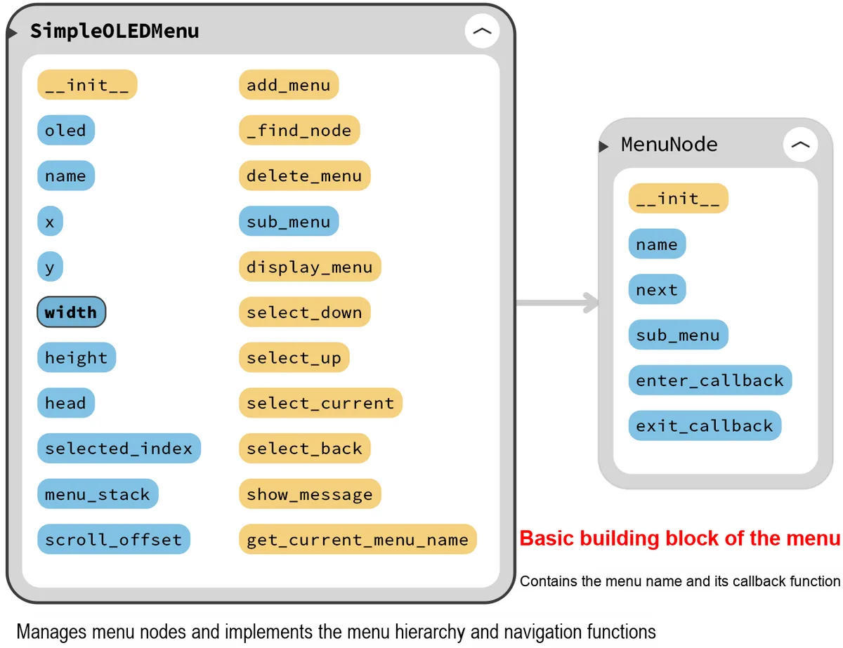
We have defined the following attributes in the MenuNode class, and the meaning of each attribute is as follows: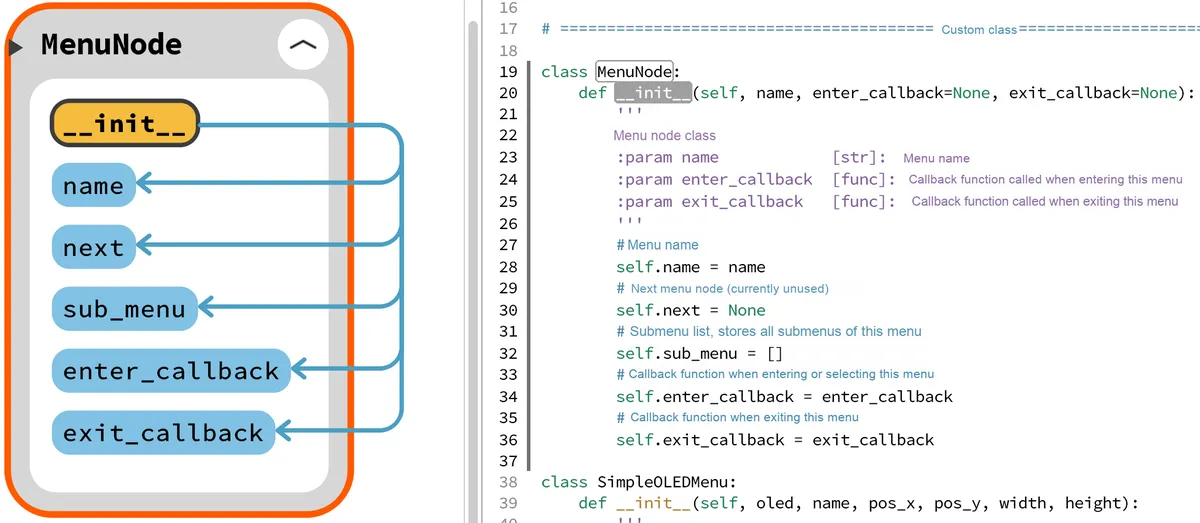
- name: Indicates the name of the menu. It is a string type, which is used to identify and distinguish different menu items when displaying the menu.
- next: A reference pointing to the next menu node, which can be used to implement a linked list structure to connect menu nodes at the same level
- sub_menu: A list that stores all submenu nodes of the current menu node, enabling the formation of a tree-like menu structure
- enter_callback: An optional callback function that is invoked when the user enters this menu, used to perform initialization or data loading operations
- exit_callback: An optional callback function that is invoked when the user exits this menu, used to perform operations such as cleanup or state saving.
SimpleOLEDMenu class has the following methods:
- Initialization method: We need to pass into it the OLED display object, the menu name, the starting X and Y coordinates of the menu on the display screen, as well as the width and height of the menu, then create a root menu node instance to represent the starting position of the menu; set
self.selected_indexthe index of the currently selected menu item to be initialized to 0; create a list to store the records of menu levels, and when the user enters a submenu, push the current menu into themenu_stackstack, so that it is possible to return to the previous level of the menu;Finally, set the current scroll offset, which is initialized to 0, to handle the situation where the menu items exceed the visible range, ensuring that users can scroll up and down to view all menu items.
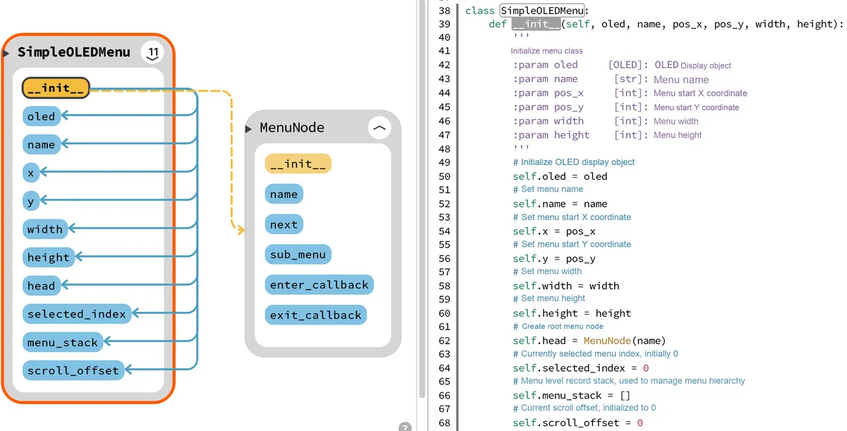
- Menu Addition
add_menuMethod: This method first performs parameter checking to ensure that the directory name has a valid length and no menu node with a duplicate name has been added; then it uses the providedname,enter_callbackandexit_callbackto create a newMenuNodeinstance, and then adds the newly created menu node to the specified parent menu node. Ifparent_nameisNone, it indicates that this is a root menu node, and the new node will be added to the root menu'ssub_menulist
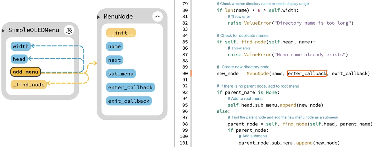
When adding a node if a parent node exists, a private method _find_node will be used to find the parent node; if the parent node is found, the new node will be added as a submenu of this parent node. In the private method _find_node, we first check whether the current menu node is the parent node to be found. If the current node is not the target parent node, we will iterate through all submenus of the current node and make a recursive call to the _find_node method to perform the search
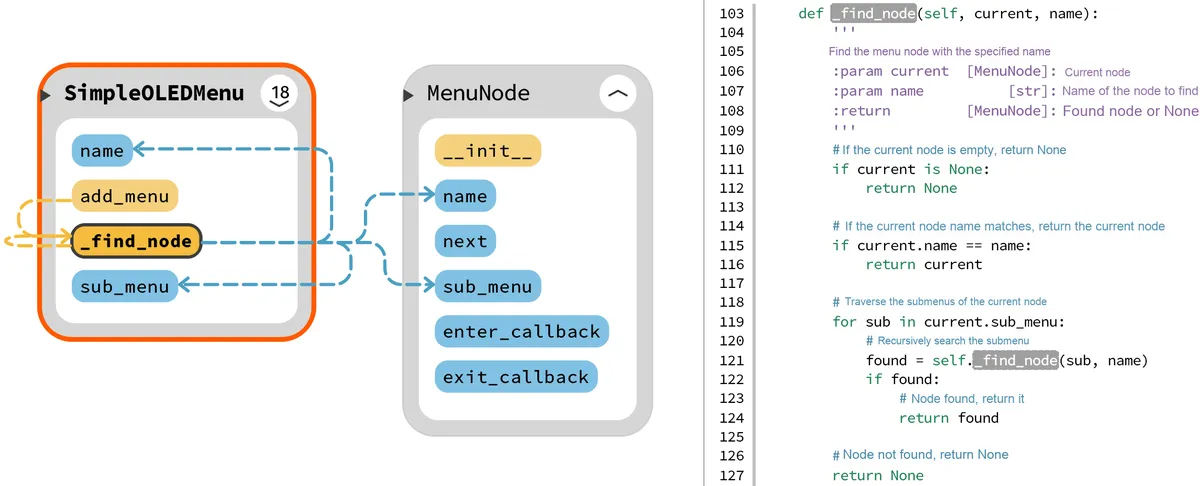
- Menu Display
display_menuMethod: This method is used to display the content of the current menu on the OLED display. First, we clear the OLED display to get it ready for showing the new menu; then sety_offsetas the starting Y-coordinate of the menu (self.y), which is used to control the vertical position of menu items;Next, iterate through the submenus of the current menu(self.head.sub_menu). For each menu item, check whether it is selected; if it is a selected item, display it in inverted colors (using thefill_rectmethod) and set the font color to black.If the number of menu items exceeds the visible height, calculate and display the visible menu items. Here, we first clear the previous menu area, then calculate the number of displayable menu items, and usescroll_offsetto determine which items are within the current visible range. For each menu item in the visible range, also check its selected state and perform corresponding display processing; finally, callself.oled.show ()to update the OLED display
- Menu Selection
select_upandselect_downMethods: These two methods are used to select menu items downwards and upwards in the menu respectively. Their basic logic is to modifyself.selected_indexto move the selected menu item, then determine whetherselected_indexexceeds the number of menu items, and then check whether the currently selected item is out of the visible range. If it is out of range, modifyscroll_offsetto implement menu scrolling, and then callself.display_menu ()to refresh the OLED display
- Menu entry and selection
select_currentMethod: This method first obtains the currently selected menu item based onself.selected_index. Ifcurrent_menuexists, proceed to the subsequent steps; if there is a defined entry callback for the current menu, call this function, which can be used to perform operations related to entering this menu;Ifcurrent_menuhas submenus, push the current menu (i. e.,self.head) intoself.menu_stackso that it can be restored when returning, meanwhile updateself.headtocurrent_menuto enter the new submenu, reset the selected index and scroll offset, and finally callself.display_menu ()to refresh the OLED display
- Menu Return
select_backMethod: First check ifself.menu_stackis not empty. If the stack is not empty, it indicates that there is a parent menu to return to; if the current menu has a defined exit callback function (exit_callback), call this function, then pop the parent menu frommenu_stackand assign it toself.headto switch to the previous level of menu;If the new current menu (i. e., the pop-up menu) has a defined enter callback function (enter_callback), this function will be invoked to perform operations related to entering this menu; finally,self.selected_indexwill be reset to 0, so that the first item in the new menu can be selected, andself.display_menu ()will be called to refresh the OLED display
- Menu Deletion
delete_menuMethod: Traverseself.head.sub_menuusing a list comprehension, and retain the menu nodes whose names are not equal to the name to be deleted (name); after the deletion operation, check the length ofself.head.sub_menu; if the length is zero, it indicates that there are no submenu items under the current menu, then call theself.select_back ()method to return to the previous level menu;Finally, callself.display_menu ()to refresh the OLED display so as to reflect the current menu changes
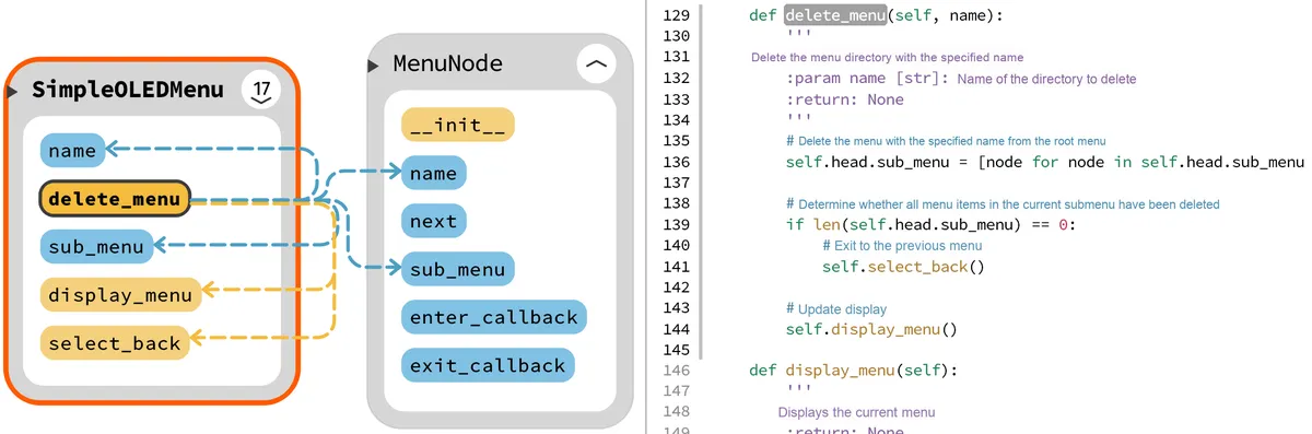
- Message Prompt
show_messageMethod: First, the method checks the length of the message to be displayed; if the message length exceeds 13 characters, an exception is thrown to ensure that the message can be fully displayed on the OLED display screen;Next, obtain the width and height of the OLED display, set the width (rect_width) and height (rect_height) of the rectangle to be drawn, calculate the top-left corner coordinates(x, y)of the rectangle to center it on the screen, then callself.oled.fill (0)to clear the OLED display in preparation for showing new content;After clearing the display, the current menu is redisplayed. Theself.oled.rect ()method is used to draw the outer rectangular border, and theself.oled.fill_rect ()method is used to fill the inner rectangle to create a prompt box. Next, the display position of the message is calculated to center it within the rectangle, then theoled.text ()method is used to draw the message text at the calculated position. Finally, the OLED display is refreshed, the display is cleared after a 1-second pause, and the function to display the current menu is called again.
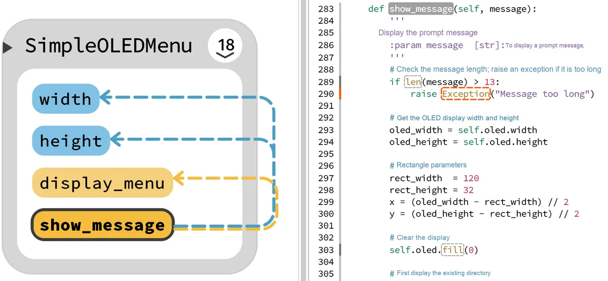
- Get the name of the currently selected menu
get_current_menu_nameMethod: First, checkself.selected_indexto determine the currently selected menu. Ifselected_indexis less than the number of sub-items in the current menu, get the corresponding menu node; otherwise, setcurrent_menutoNone; ifcurrent_menuexists, return its name (current_menu.name);This method is typically used in scenarios where the name of the current menu needs to be displayed or processed, for example, when it is necessary to confirm which menu the user is in before performing a certain operation.
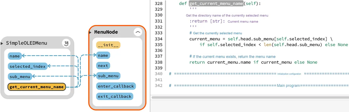
In the main program, we have built an interrupt handling function detect_interrupt to respond to the 5-way button, update the current menu by matching the button status, and execute the corresponding menu operations. The sample code is as follows:
# Python env   : MicroPython v1.23.0
# -*- coding: utf-8 -*-
# @Time    : 2024/9/25 3:02 PM
# @Author  : Li Qingshui
# @File    : main.py
# @Description : I2C experiment: use the PCF8575 chip to read 5D joystick data and control the OLED screen menu

# ======================================== Import Modules =========================================

# Hardware-related modules
from machine import I2C, Pin
# Time-related modules
import time
# Import the custom PCF8575 class
from pcf8575 import PCF8575
# Import the OLED screen modules
from SSD1306 import SSD1306_I2C
# Import the custom OLED menu library
from menu import SimpleOLEDMenu

# ======================================== Global Variables ============================================

# PCF8575 chip address
PCF8575_ADDRESS = 0
# OLED screen address
OLED_ADDRESS = 0

# Definition of the five-way buttons
KEYS = {
    0b1000000011111111 : "UP",
    0b0000100011111111 : "DOWN",
    0b0100000011111111 : "LEFT",
    0b0010000011111111 : "RIGHT",
    0b0001000011111111 : "CENTER"
}

# Record the button currently pressed
current_key = None
# Variable value
value = 10
# Parameter value
param = 0

# ======================================== Functions ============================================

def led_on() -> None:
    """
    Turn on the LED.

    Args:
        None

    Returns:
        None
    """
    # Declare global variables
    global LED

    # Set to high level to turn on the LED
    LED.value(1)
    print("LED ON")

def led_off() -> None:
    """
    Turn off the LED.

    Args:
        None

    Returns:
        None
    """
    # Declare global variables
    global LED

    # Set to low level to turn off the LED
    LED.value(0)
    print("LED OFF")

def print_message() -> None:
    """
    Display a prompt message on the OLED screen.

    Args:
        None

    Returns:
        None
    """
    # Declare global variables
    global menu

    # Display the prompt message
    menu.show_message("No Sub Option")

def view_variable() -> None:
    """
    Display the variable value on the OLED screen.

    Args:
        None

    Returns:
        None
    """
    # Declare global variables
    global value

    # Display the variable value
    menu.show_message(f"Variable: {value}")

def set_parameter() -> None:
    """
    Display the parameter value on the OLED screen and update the parameter.

    Args:
        None

    Returns:
        None
    """
    # Declare global variables
    global param

    # Assume the logic for setting the parameter is to add 1 to it
    param += 1
    # Display the parameter value
    menu.show_message(f"Parameter: {param}")

def detect_interrupt(pin : Pin) -> None:
    """
    Interrupt handler, triggered when the state of an input pin on the PCF8575 chip port changes.

    Args:
        pin (machine.Pin): The interrupt pin instance.

    Returns:
        None
    """

    # Declare global variables
    global pcf8575, current_key, KEYS, menu

    # If the PCF8575 chip port is not binary 0000000011111111 after triggering
    if pcf8575.port != 255:
        # Print the PCF8575 chip port status
        print("PCF8575 Port: {:016b}".format(pcf8575.port))

        # Check the port status to determine which button was pressed
        for key, name in KEYS.items():
            # If the port status matches the current button code
            if pcf8575.port == key:
                # Then record the state of the last button press
                current_key = name
                # Print debug information
                print(f"Button {current_key} pressed")

                # Update the menu according to the button action
                if current_key == "UP":
                    # Select the previous menu item (up)
                    menu.select_up()
                elif current_key == "DOWN":
                    # Select the next menu item (down)
                    menu.select_down()
                elif current_key == "LEFT":
                    # Left: return to the parent menu
                    menu.select_back()
                elif current_key == "RIGHT":
                    # Right: delete the currently selected menu
                    menu.delete_menu(menu.head.sub_menu[menu.selected_index].name)
                elif current_key == "CENTER":
                    # Press: select the current menu item and enter it
                    menu.select_current()

                # Print the currently selected menu item
                print("Select Menu: {}".format(menu.get_current_menu_name()))

# ======================================== Custom Classes ============================================

# ======================================== Initialization ==========================================

# Power-on delay of 3 s
time.sleep(3)
# Print debug message
print("FreakStudio: Read the status of 5D button by PCF8575")

# Set GPIO 25 as the LED output pin, pull-down resistor enabled
LED = Pin(25, Pin.OUT, Pin.PULL_DOWN)

# Create a hardware I2C instance using the I2C1 peripheral, clock frequency 400KHz, SDA pin 6, SCL pin 7
i2c_pcf8575 = I2C(id=1, sda=Pin(6), scl=Pin(7), freq=400000)

# Start scanning for devices on the I2C bus and return a list of slave addresses
devices_list = i2c_pcf8575.scan()
print('START I2C SCANNER')

# If devices_list is empty, no device is connected to the I2C bus
if len(devices_list) == 0:
    print("No i2c device !")
# If not empty, print the slave device addresses
else:
    print('i2c devices found:', len(devices_list))
    # Iterate over the slave device address list
    for device in devices_list:
        # Check whether the device address is the PCF8575 address
        if device >= 0x20 and device <= 0x27:
            print("PCF8575 hexadecimal address: ", hex(device))
            PCF8575_ADDRESS = device

# Create a PCF8575 class instance, interrupt pin is 8, callback function is detect_interrupt
pcf8575 = PCF8575(i2c_pcf8575, PCF8575_ADDRESS, interrupt_pin=Pin(8), callback=detect_interrupt)
pcf8575.port = 0x00FF

# Create a hardware I2C instance using the I2C1 peripheral, clock frequency 400KHz, SDA pin 6, SCL pin 7
i2c_oled = I2C(id=1, sda=Pin(6), scl=Pin(7), freq=400000)

# Start scanning for devices on the I2C bus and return a list of slave addresses
devices_list = i2c_oled.scan()
print('START I2C SCANNER')

# If devices_list is empty, no device is connected to the I2C bus
if len(devices_list) == 0:
    print("No i2c device !")
# If not empty, print the slave device addresses
else:
    print('i2c devices found:', len(devices_list))
    # Iterate over the slave device address list
    for device in devices_list:
        if device >= 0x3C and device <= 0x3D:
            print("OLED hexadecimal address: ", hex(device))
            OLED_ADDRESS = device

# Create an SSD1306 OLED screen instance, width 128 pixels, height 64 pixels, without external power supply
oled = SSD1306_I2C(i2c_oled, OLED_ADDRESS, 128, 64,False)

# Print the status of each PCF8575 port
print("PCF8575 16 bits state: {:016b}".format(pcf8575.port))

# ========================================  Main Program  ===========================================

# Create a menu instance
menu = SimpleOLEDMenu(oled, "Main Menu", 0, 0, 128, 64)

# Add main menu options
menu.add_menu("Option1")
menu.add_menu("Option2")
menu.add_menu("Option3")
menu.add_menu("Option4")
menu.add_menu("Option5")
menu.add_menu("Option6")
menu.add_menu("Option7")
menu.add_menu("Option8")
menu.add_menu("Option9")
menu.add_menu("Option10")
menu.add_menu("Option11")
menu.add_menu("Option12")
menu.add_menu("LED Option")
menu.add_menu("Variable Option",enter_callback=view_variable)
menu.add_menu("Parameter Option",enter_callback=set_parameter)

# Add a submenu under Option1
menu.add_menu("Sub Option1", parent_name="Option1", enter_callback=print_message)
menu.add_menu("Sub Option2", parent_name="Option1")
menu.add_menu("Sub Option3", parent_name="Option1")
menu.add_menu("Sub Option4", parent_name="Option1")
menu.add_menu("Sub Option5", parent_name="Option1")
menu.add_menu("Sub Option6", parent_name="Option1")
menu.add_menu("Sub Option7", parent_name="Option1")
menu.add_menu("Sub Option8", parent_name="Option1")

# Add the LED control menu under LED Option
menu.add_menu("LED ON", parent_name="LED Option", enter_callback=led_on)
menu.add_menu("LED OFF", parent_name="LED Option", enter_callback=led_off)

# Update the displayed menu
menu.display_menu()

# Main loop
while True:
    # Delay 1s
    time.sleep(0.5)
    # Change the variable value
    value = value + 1
First, we define a KEYS dictionary, which uses binary encoding to map the output result of the PCF8575 chip when each key in the 5-way keypad is pressed, so as to facilitate subsequent judgment of which key is pressed. Here, the COM terminal of our 5-way keypad is connected to the VDD of the IO expansion module, and it will go high when any direction key is pressed:
# Definition of the five-way buttons
KEYS = {
    0b1000000011111111 : "UP",
    0b0000100011111111 : "DOWN",
    0b0100000011111111 : "LEFT",
    0b0010000011111111 : "RIGHT",
    0b0001000011111111 : "CENTER"
}
When the state of the input pins of the PCF8575 changes, its INT pin will change accordingly. Here, we use the GPIO12 pin of the Raspberry Pi Pico for sensing and configure it to be triggered on the falling edge:
# Create a PCF8575 class instance, interrupt pin is 12, callback function is detect_interrupt
pcf8575 = PCF8575(i2c_pcf8575, PCF8575_ADDRESS, interrupt_pin=Pin(12), callback=detect_interrupt)
When an external interrupt occurs, the preset callback function detect_interrupt will be invoked:
def detect_interrupt(pin : Pin) -> None:
    """
    Interrupt handler, triggered when the state of an input pin on the PCF8575 chip port changes.

    Args:
        pin (machine.Pin): The interrupt pin instance.

    Returns:
        None
    """

    # Declare global variables
    global pcf8575, current_key, KEYS, menu

    # If the PCF8575 chip port is not binary 0000000011111111 after triggering
    if pcf8575.port != 255:
        # Print the PCF8575 chip port status
        print("PCF8575 Port: {:016b}".format(pcf8575.port))

        # Check the port status to determine which button was pressed
        for key, name in KEYS.items():
            # If the port status matches the current button code
            if pcf8575.port == key:
                # Then record the state of the last button press
                current_key = name
                # Print debug information
                print(f"Button {current_key} pressed")

                # Update the menu according to the button action
                if current_key == "UP":
                    # Select the previous menu item (up)
                    menu.select_up()
                elif current_key == "DOWN":
                    # Select the next menu item (down)
                    menu.select_down()
                elif current_key == "LEFT":
                    # Left: return to the parent menu
                    menu.select_back()
                elif current_key == "RIGHT":
                    # Right: delete the currently selected menu
                    menu.delete_menu(menu.head.sub_menu[menu.selected_index].name)
                elif current_key == "CENTER":
                    # Press: select the current menu item and enter it
                    menu.select_current()

                # Print the currently selected menu item
                print("Select Menu: {}".format(menu.get_current_menu_name()))
It checks the current port status, and if a key is pressed, it updates the menu status according to the type of the pressed key.
In the main program, we create an OLED menu:
# Create a menu instance
menu = SimpleOLEDMenu(oled, "Main Menu", 0, 0, 128, 64)

# Add main menu options
menu.add_menu("Option1")
menu.add_menu("Option2")
menu.add_menu("Option3")
menu.add_menu("Option4")
menu.add_menu("Option5")
menu.add_menu("Option6")
menu.add_menu("Option7")
menu.add_menu("Option8")
menu.add_menu("Option9")
menu.add_menu("Option10")
menu.add_menu("Option11")
menu.add_menu("Option12")
menu.add_menu("LED Option")
menu.add_menu("Variable Option",enter_callback=view_variable)
menu.add_menu("Parameter Option",enter_callback=set_parameter)

# Add a submenu under Option1
menu.add_menu("Sub Option1", parent_name="Option1", enter_callback=print_message)
menu.add_menu("Sub Option2", parent_name="Option1")
menu.add_menu("Sub Option3", parent_name="Option1")
menu.add_menu("Sub Option4", parent_name="Option1")
menu.add_menu("Sub Option5", parent_name="Option1")
menu.add_menu("Sub Option6", parent_name="Option1")
menu.add_menu("Sub Option7", parent_name="Option1")
menu.add_menu("Sub Option8", parent_name="Option1")

# Add the LED control menu under LED Option
menu.add_menu("LED ON", parent_name="LED Option", enter_callback=led_on)
menu.add_menu("LED OFF", parent_name="LED Option", enter_callback=led_off)

# Update the displayed menu
menu.display_menu()
We have added the menu items and the corresponding callback functions. The menu structure and callback methods are shown in the following figure:
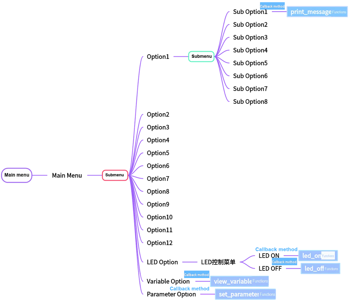
Here, the meaning of each callback method is as follows:
view_variable: A message bound to theVariable Optionmenu item that displays the current variable valueset_parameter: Bound to theParameter Optionmenu item, it adds parameter values and displays them.print_message: Bound toSub Option1to display a prompt messageled_on: Bound to theLED ONmenu item, used to turn on the LED lightled_off: Bound to theLED OFFmenu item, used to turn off the LED.
Finally, we define an infinite loop to change the value of the variable.
Burn the code, open the terminal, and the following content will be displayed:
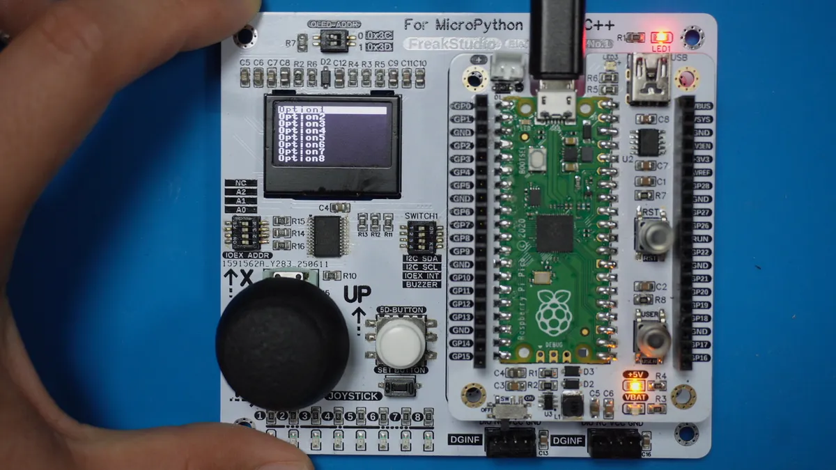
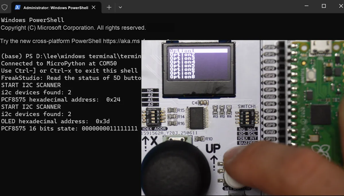
As we can see, the terminal displays the addresses of the OLED screen and the PCF8575 chip, and the Main Menu parent menu has been initialized on the OLED screen, with the first menu item currently selected. When we press the Down key of the 5-way button, we can see that the selection has successfully moved down one line on the OLED screen; meanwhile, the terminal outputs the port level of the PCF8575 chip, the pressed key, and the currently selected menu option:
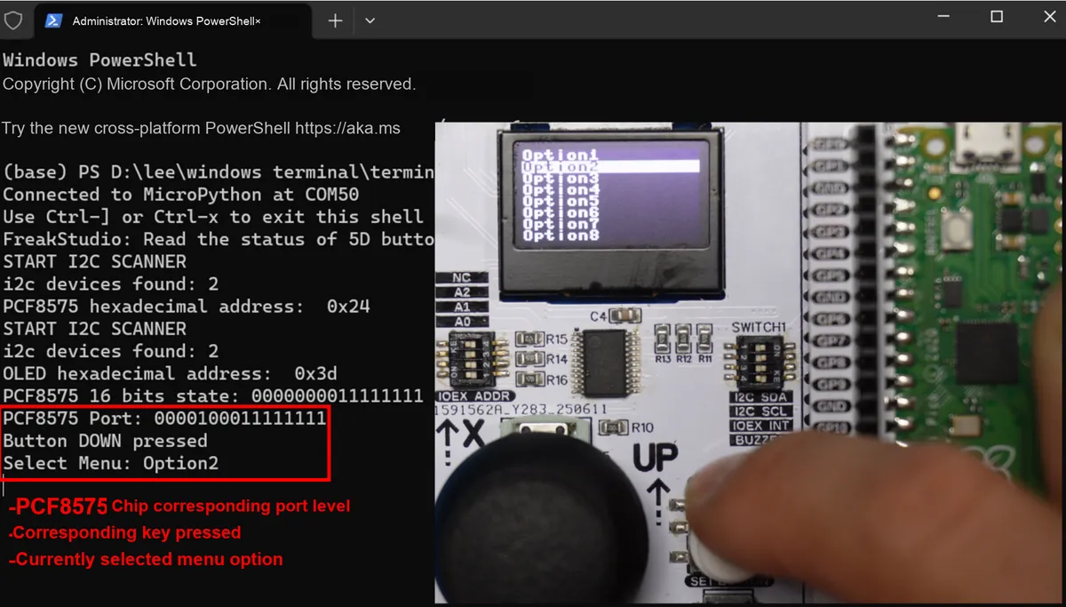
Go back to the Option1 menu item, and after pressing the CENTER key, we will be navigated to its submenu:
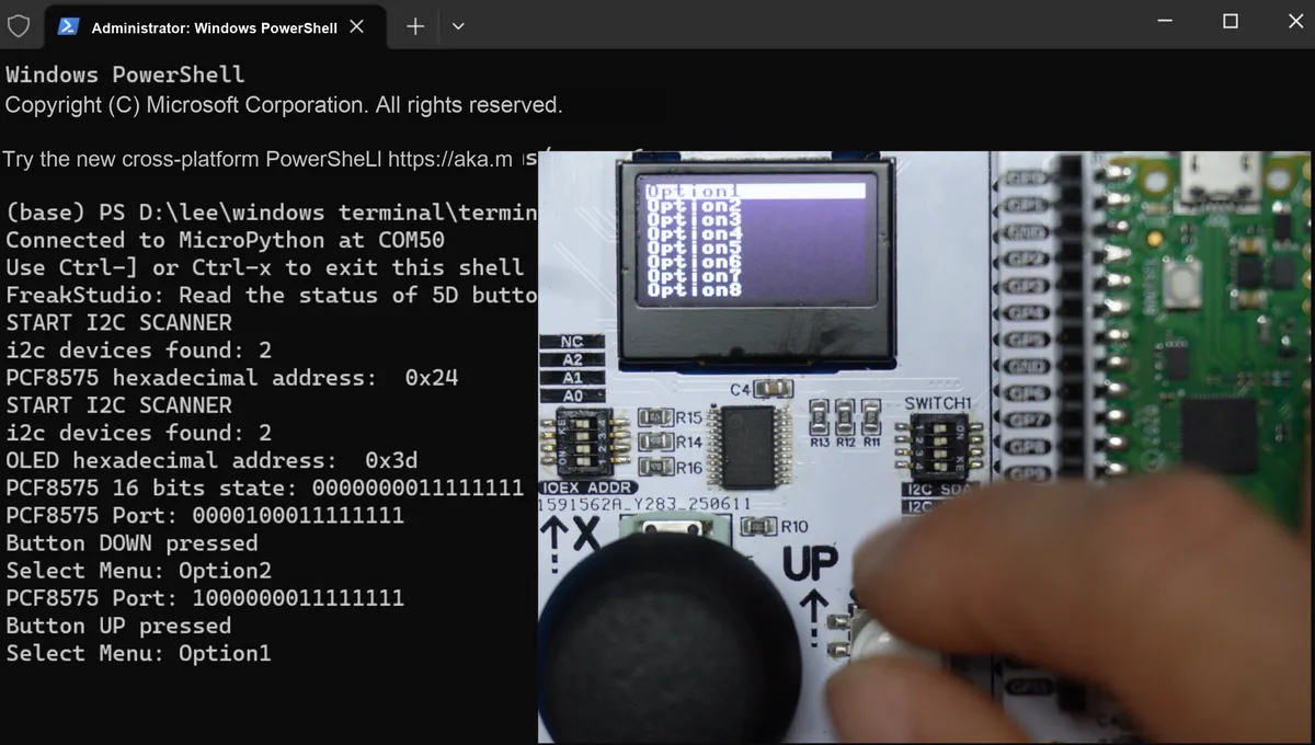
Select Sub Option1 menu item, press the CENTER key, and you will see a debug message box indicating that the current menu item has no submenu items:
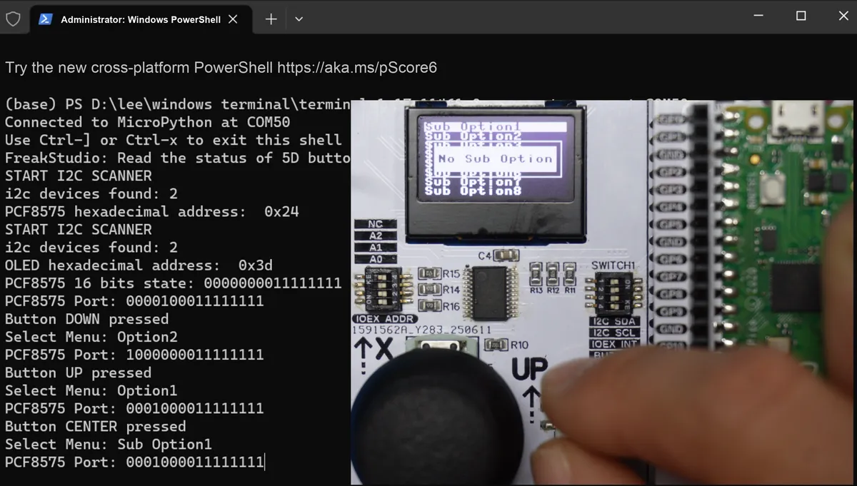
Press the LEFT key to return to the Main Menu:
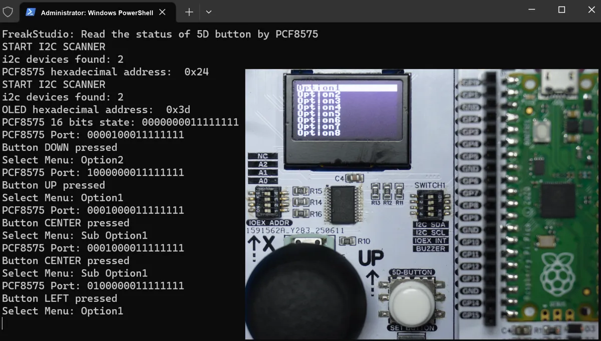
Press UP key, and the menu will scroll back to the last Parameter Option menu item:
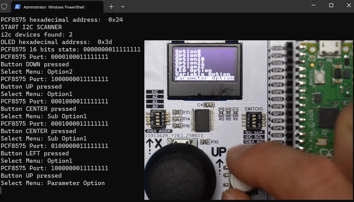
Press the CENTER key twice in succession, and you will see its parameter value increment:
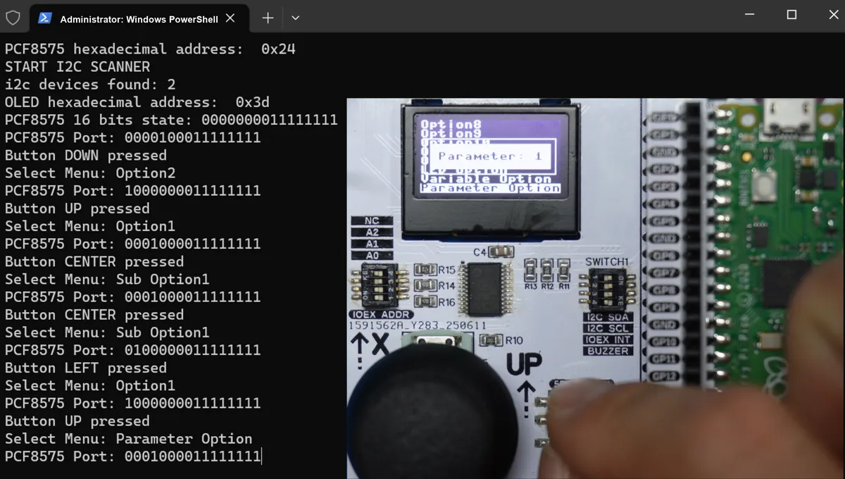
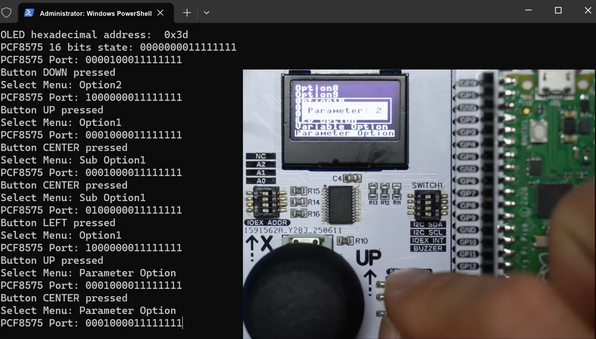
Move up one item to the Variable Option menu item, then press the CENTER key twice in succession, and we can see the variable value change:
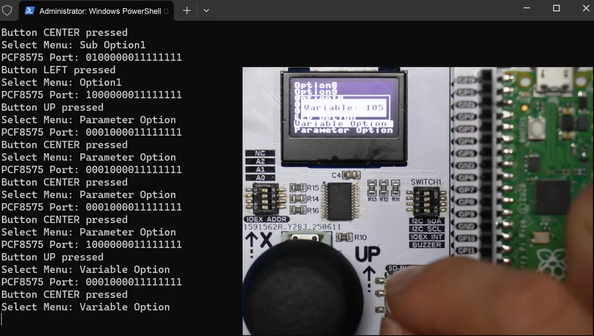
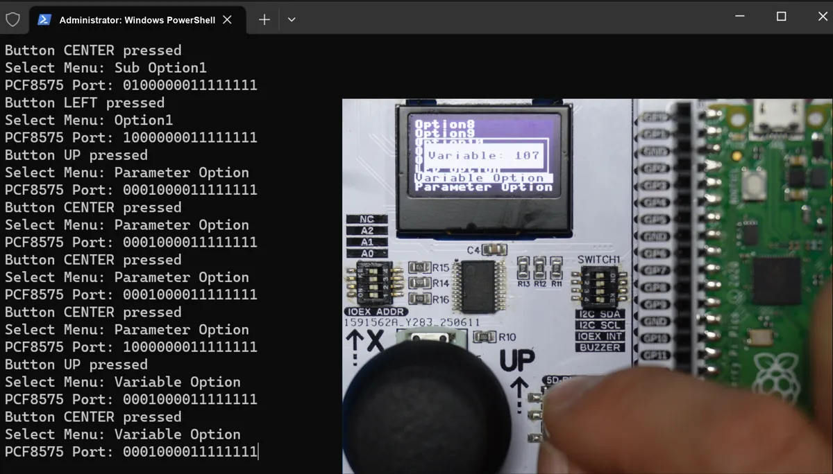
Move up one more item to LED Option, then press the CENTER key to enter its submenu:
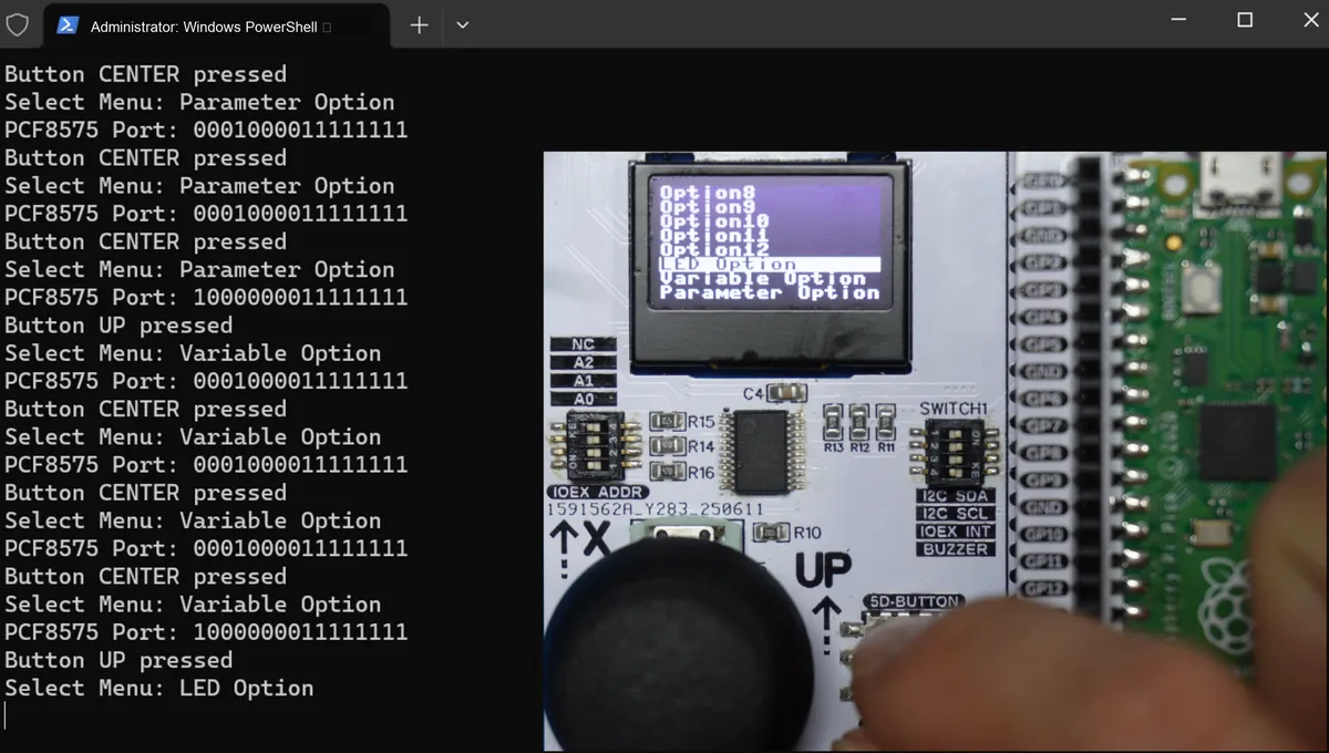
Select the corresponding LED control option and press the CENTER key to turn the LED on or off:
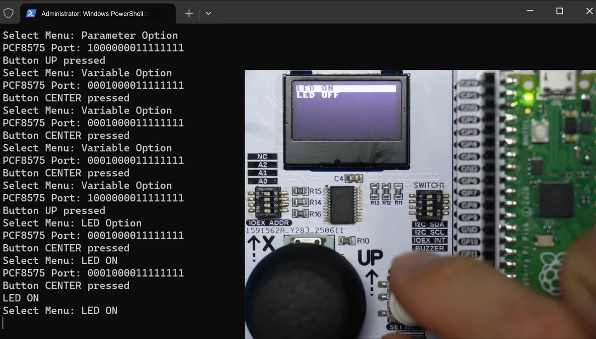
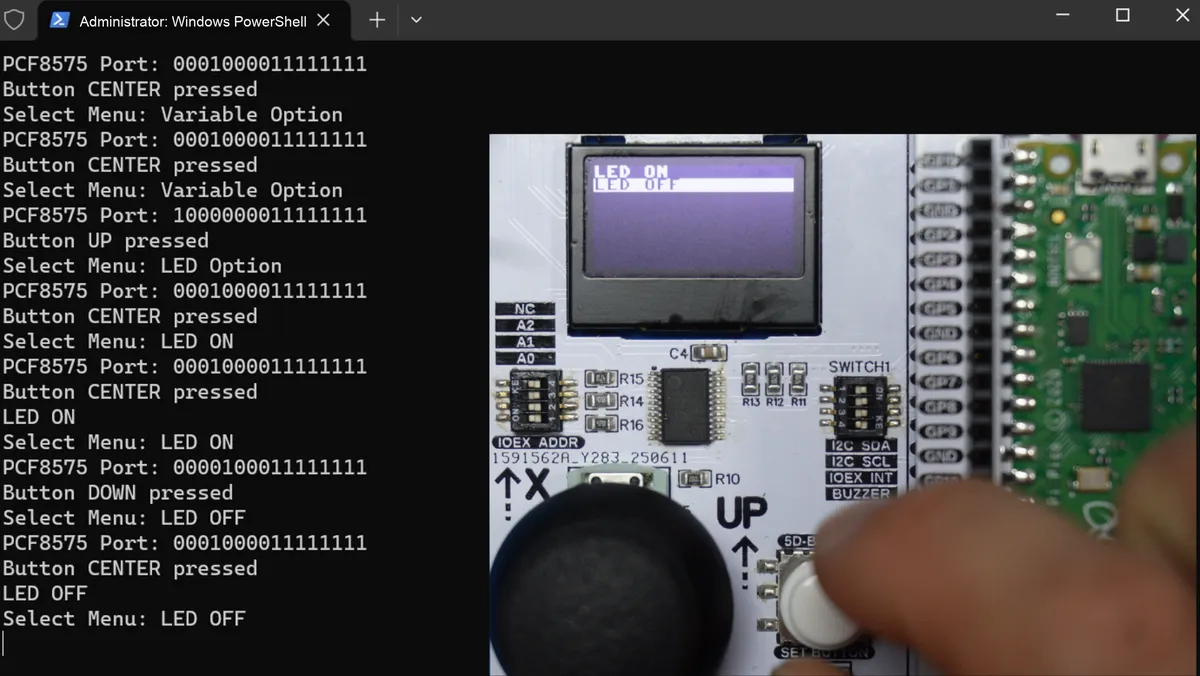
3.3.2 Application Experiment.mp4 219.3 MB
3.4 Reading and Writing External EEPROM via I2C
3.4.1 Introduction to AT24CXX Series Chips
3.4.1.1 Introduction to External EEPROM Chip
External EEPROM chip is a common non-volatile memory device, which is often used in embedded systems to store parameters such as system configuration and calibration data. Its storage capacity ranges from several Kbits to several Mbits. We usually use the I2C protocol to communicate with external EEPROM chips, which features data retention after power-off and support for individual read and write of any byte; EEPROM has a fast read speed, generally ranging from tens to hundreds of nanoseconds, but a slow write speed, generally ranging from several milliseconds to tens of milliseconds, and its erase-write life is typically between 100,000 and 1 million cycles.
Compared with external Flash chips, external EEPROM chips feature smaller capacity and slower write speed, yet they support independent erasure and writing of individual bytes and boast a higher number of write cycles, making them suitable for storing small data that requires frequent updates.
Here, it is necessary to distinguish between the units Kbit (kilobit) and KB (kilobyte): 1 Kbit = 1000 bits, while 1 KB = 1024 bytes. Since one byte consists of eight bits, 1 KB = 8 Kbit.
3.4.1.2 Introduction to AT24CXX Series Chips
The most commonly used EEPROM chips are the AT24CXX series, which are EEPROM chips manufactured by Microchip Technology. They adopt the I2C interface, support multi-master mode, and facilitate convenient communication with microcontrollers; meanwhile, they feature a wide power supply voltage range from 1.7V to 5.5V, supporting both low-voltage and standard-voltage operations. They support a maximum communication rate of 400kHz at 1.7V, while the maximum communication rate can reach 1MHz at 2.5V, 2.7V and 5.0V.
The AT24CXX series chips support storage capacities ranging from 1Kbit to 512Kbit, where XX indicates a storage capacity of XX Kbit (e. g., AT24C01, AT24C256):
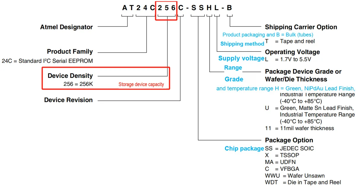
The following is the AT24C256 chip we commonly use, with a capacity of 256 Kbit:
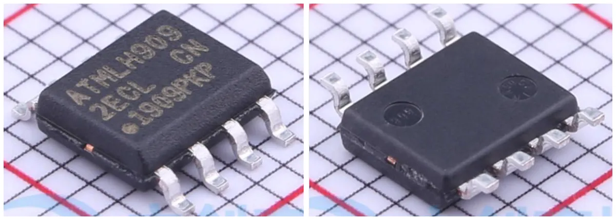
The AT24C256 chip also features the following characteristics:
- Noise Suppression: Built-in Schmitt trigger and filtered inputs enhance anti-interference capability
- Write-protect pin: provides hardware protection to prevent accidental writing
- Self-timed write cycle: Maximum write time is 5 milliseconds
- High reliability: with write cycle endurance up to 1,000,000 cycles and data retention time up to 40 years
Here, the AT24C256 chip divides its 256 Kbit storage space into 512 pages, each containing 64 bytes. The address range of the first page is 0x0000~0x003F, and the rest are evenly divided into 512 pages in sequence, as shown in the following figure:
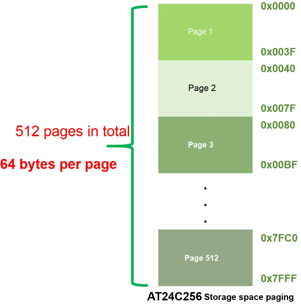
The AT24C256 chip supports two write modes: page write and partial page write.
- Page Write: A complete page (typically 64 bytes) is written to the EEPROM in a single operation. During a page write, all data must be written to the page; if only partial data needs to be written, the remaining portion of the page will be overwritten with the new data. Page write operations are generally fast.
- Partial page write: It allows selectively writing a small amount of data within a single page without overwriting the entire page. Users can update only specific bytes in the page while leaving the rest unchanged, which is extremely useful for data that requires frequent updates to particular bytes; however, partial page writes are relatively slow.
3.4.1.3 Introduction to Pins and Internal Structure of AT24C256 Chip
The pin names and functions of the AT24C256 chip are as follows:
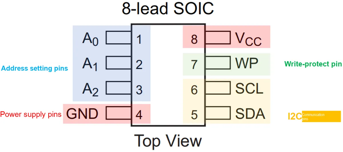
Among them, pins A2, A1 and A0 are device address inputs, which can be connected to GND or VCC to set the address of the AT24C256 chip. If these pins are left floating (i. e., not externally connected to GND or VCC), pins A2, A1 and A0 will be internally pulled low to GND; here, when pins A2, A1 and A0 are connected to VCC via pull-up resistors, it is recommended that the resistance value of the pull-up resistors be less than 10kΩ.
The communication address setting of the AT24C256 chip is as follows:
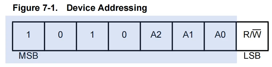
Among these bits, the first four are fixed as 1010, which is the universal standard for 2-wire EEPROM devices, while the last three correspond to the device's address input pins A2, A1 and A0; by connecting these address input pins to VCC or GND, up to eight such devices can be connected to the same bus.
The WP pin is a write-protect input pin: when connected to GND, it allows normal write operations; when connected to VCC, all write operations will be disabled. If this pin floats, the WP pin will be internally pulled down to GND. When the WP pin is connected to VCC via a pull-up resistor, it is recommended that the resistance of the pull-up resistor be less than 10kΩ.
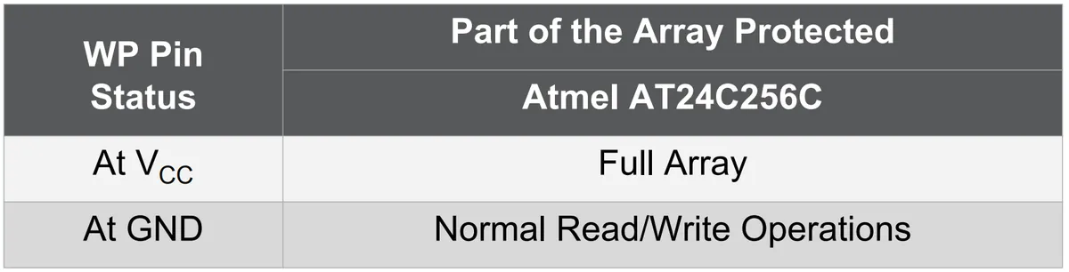
SCL and SDA are the pins used for I2C communication. For the electrical parameters of I2C protocol communication, please refer to the datasheet:
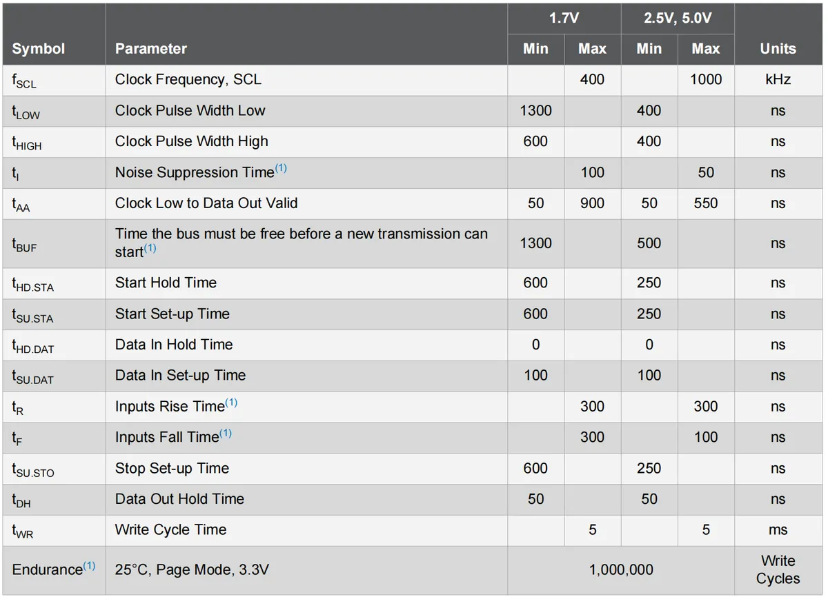
The AT24C256 chip operates with a supply voltage ranging from 1.7V to 5.5V, and its supply current varies depending on the communication speed and read/write operations:
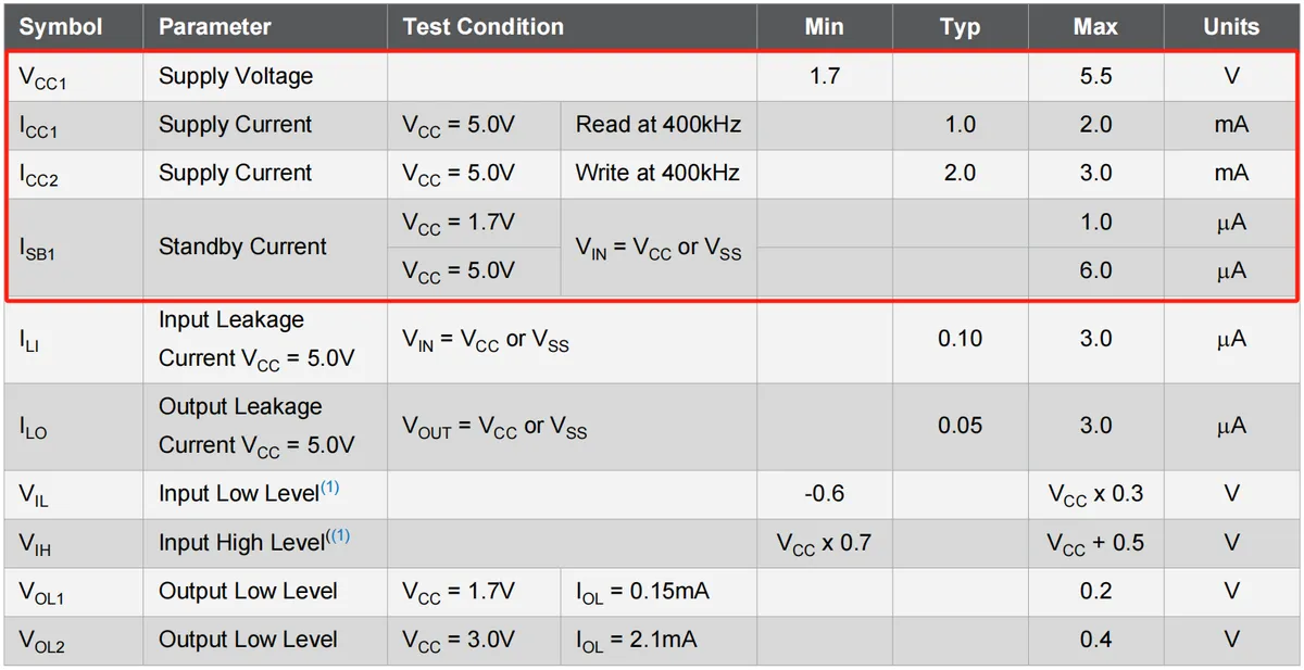
The following is the internal structure of the AT24C256C chip:
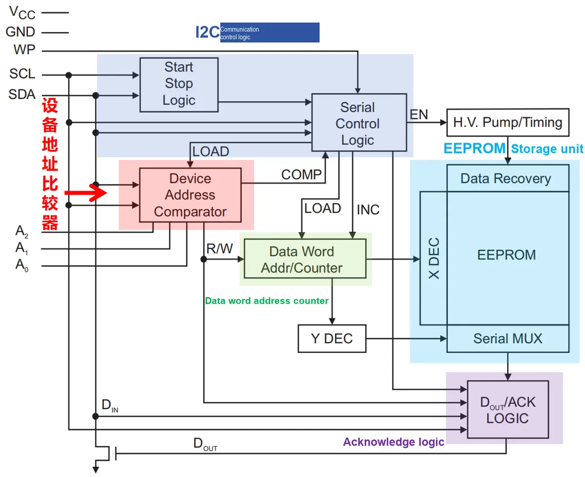
It includes the following parts:
- I2C Communication Control Logic: used to handle the start and stop conditions on the I²C bus, as well as manage and coordinate various control signals during data transmission.
- Device Address Comparator: Checks whether the incoming device address matches the internally set address to determine whether to respond to the host's command
- EEPROM memory cell: consists of a data recovery unit, a memory unit and a data selection unit. The data recovery unit is configured to handle potential data corruption or loss that may occur during the writing process; data access operations are performed in the actual memory unit, while the data selection unit is used to select data among multiple data channels.
- Data Word Address Counter: It is used to track the current data address or data word to ensure the correct reading and writing of data.
- Acknowledgment Logic: Responsible for outputting data from the EEPROM to the host and processing the acknowledgment signals
3.4.1.4 Introduction to Data Writing of AT24C256 Chip
Next, let's talk about the data read and write process of the AT24C256 chip, starting with the data write operation of the AT24C256. Here, the AT24C256C supports two write modes: Byte Write and Page Write.
- Byte Write: This mode supports writing one byte of data to any address. The microcontroller first sends a "start condition" signal, then sends the device address; after these two signals are transmitted, the AT24C256C will send an ACK (acknowledge) signal;Next, the microcontroller sends two address bytes to specify the memory location to be written, and after waiting for the acknowledge signal from the AT24C256C, the microcontroller subsequently transmits an 8-bit data word. Upon receiving the data, the AT24C256C responds with another acknowledge signal to indicate that the data has been successfully received. Finally, the microcontroller sends a "stop condition" signal to terminate the write operation.
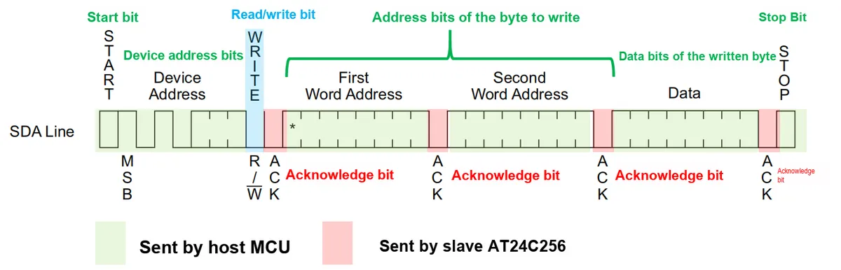
- Page Write: Similar to byte write, the microcontroller first sends a start signal, the device address bits, and the two address bytes of the first word to be written, then the microcontroller transmits the first data word. After that, the microcontroller can continue to send up to 63 data words without sending a stop signal each time; the AT24C256 chip will return an acknowledge signal after receiving each data word. When all data has been transmitted, the microcontroller finally sends a stop signal to terminate the page write operation.
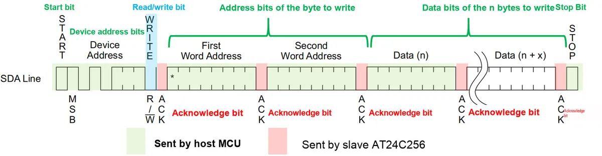
Here, the AT24C256 requires two address bytes because its storage capacity reaches 256 Kbit; the address space of one byte (8 bits) can only represent 2^8 = 256 addresses, while the AT24C256 has 256 Kbit = 32 KB = 32768 bytes, which requires 2^15 = 32768 addresses for full addressing. Therefore, two address bytes need to be sent during writing: 16 address bits can represent 2^16 = 65536 addresses, where the first address byte is usually used to represent the upper 8 bits of the address, and the second address byte is used to represent the lower 8 bits of the address.
After the AT24C256 starts a write operation (such as in byte write or page write mode), the microcontroller cannot immediately perform the next operation on the AT24C256 chip, as the AT24C256 is processing the write operation. During this period, we can continuously use the microcontroller to send a start signal, device address bits, and read/write signal; only after the AT24C256 finishes processing will it return an acknowledge signal, and we can use this method to determine whether the AT24C256 chip has completed the write operation.
It should also be noted that the write timing requirement of the AT24C256 mandates that a delay of tWR must be added after each data communication is completed to ensure that the EEPROM finishes the write operation and avoid data loss or errors, where tWR can be found in the I2C communication electrical parameters section of the datasheet:
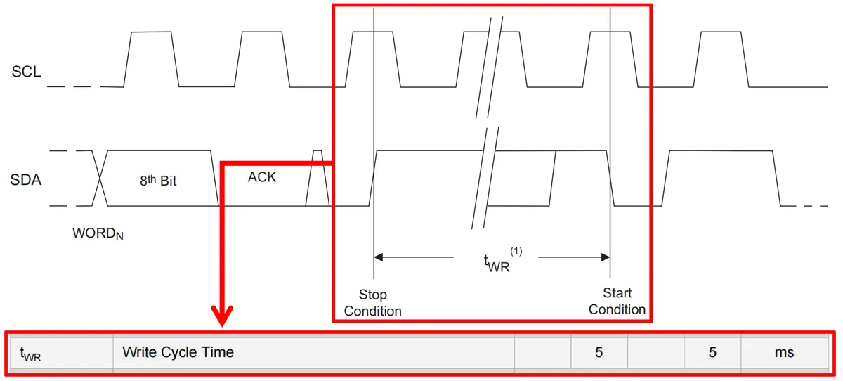
3.4.1.5 Introduction to Data Reading of AT24C256 Chip
For data reading of the AT24C256, there are three available modes: Current Address Read, Random Read and Sequential Read.
- Current Address Read: This mode is used to read the data at the current address retained after the last operation. The microcontroller sends a start signal, a device address, and a read/write bit (set to 1). After receiving the device address, the AT24C256 responds with an acknowledge signal, and then outputs the data word sequence at the current address to the microcontroller. The current address refers to the address retained after the last read or write operation, and this address is automatically incremented by 1 after the reading is completed. After receiving the data, the microcontroller does not need to return an acknowledge signal, but directly sends a stop signal to terminate the read operation.
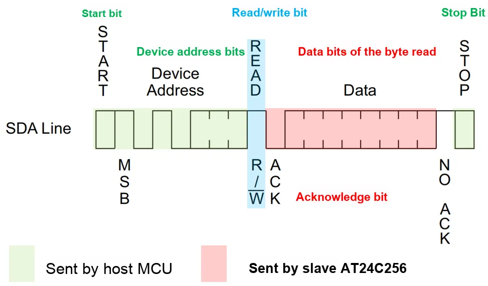
- Random Read: This method is used to read a specific byte of data at a designated address. The microcontroller first sends a start signal and the device address, then performs a "dummy write operation" with the read/write bit set to 0. This operation essentially transmits the address of the data word to be read to the AT24C256. After receiving the address, the AT24C256 sends an acknowledge signal. At this point, the microcontroller needs to send another start signal, followed by the device address with the read/write bit set to 1. Upon receiving the new device address, the AT24C256 responds with an acknowledge signal and outputs the data byte corresponding to the target address.
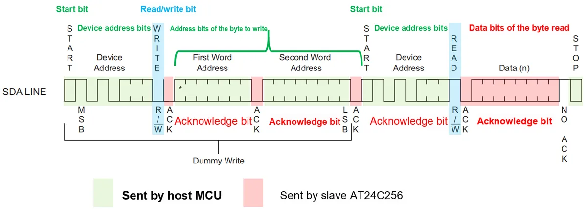
- Sequential Read: This method is used to read data consecutively starting from a certain address; during the reading process, the address will automatically increment until it reaches the last address, then wrap around back to the first address, and the specific communication process is similar to the read operation described above.
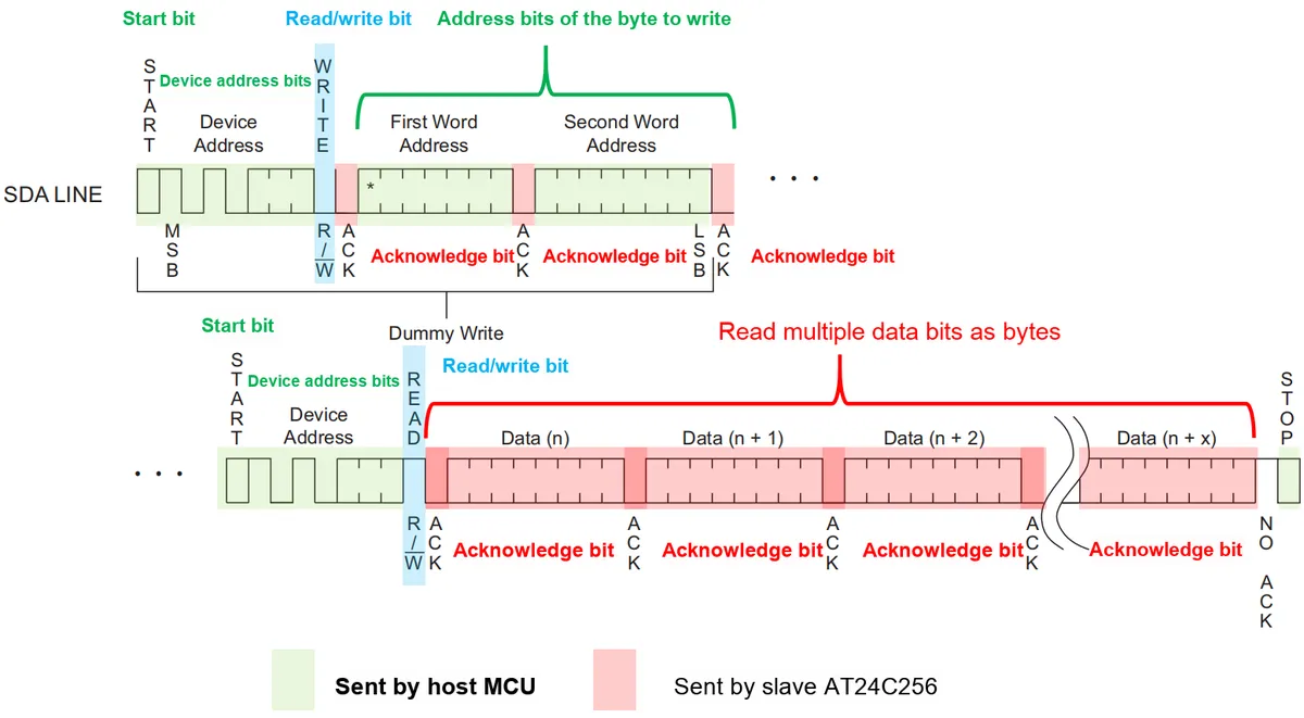
3.4.2 Reading and Writing to the AT24C256 Chip
In the following code, we implement data read and write operations with the external EEPROM chip AT24C256 via the I2C interface on the Raspberry Pi Pico, and verify the power-off data retention function of the EEPROM.
We need to insert Fengya No. 1 Board - Environment and Storage Acquisition Board into Fengya No. 1 Board - Universal Compatible Expansion Board: Fengya No. 1 Board - Environment and Storage Acquisition Board and SDA options of the SWITCH1 DIP switch on the Fengya No. 1 Board - Environment and Storage Acquisition Board :
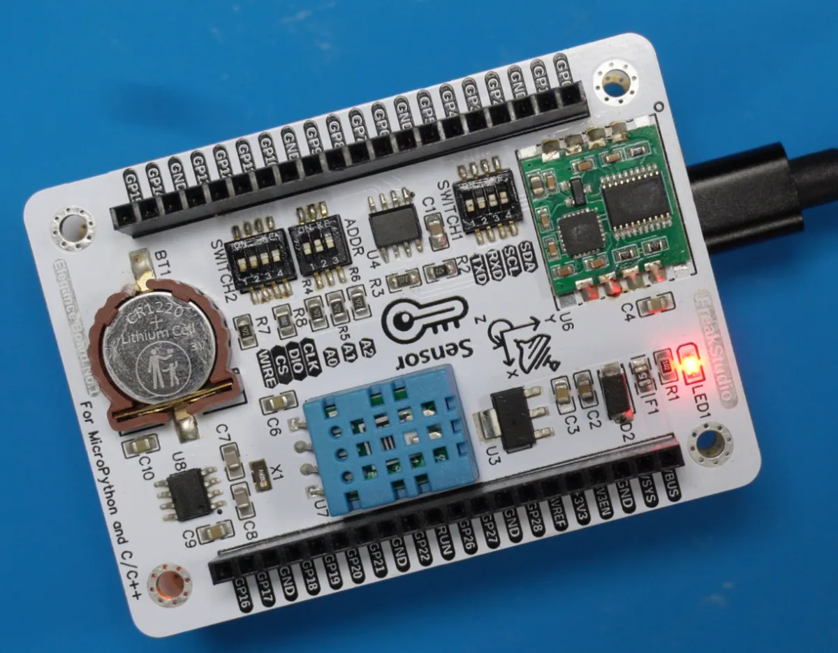
You can set its address by adjusting the Fengya No. 1 Board - Environment and Storage Acquisition Board 's ADDR DIP switches:
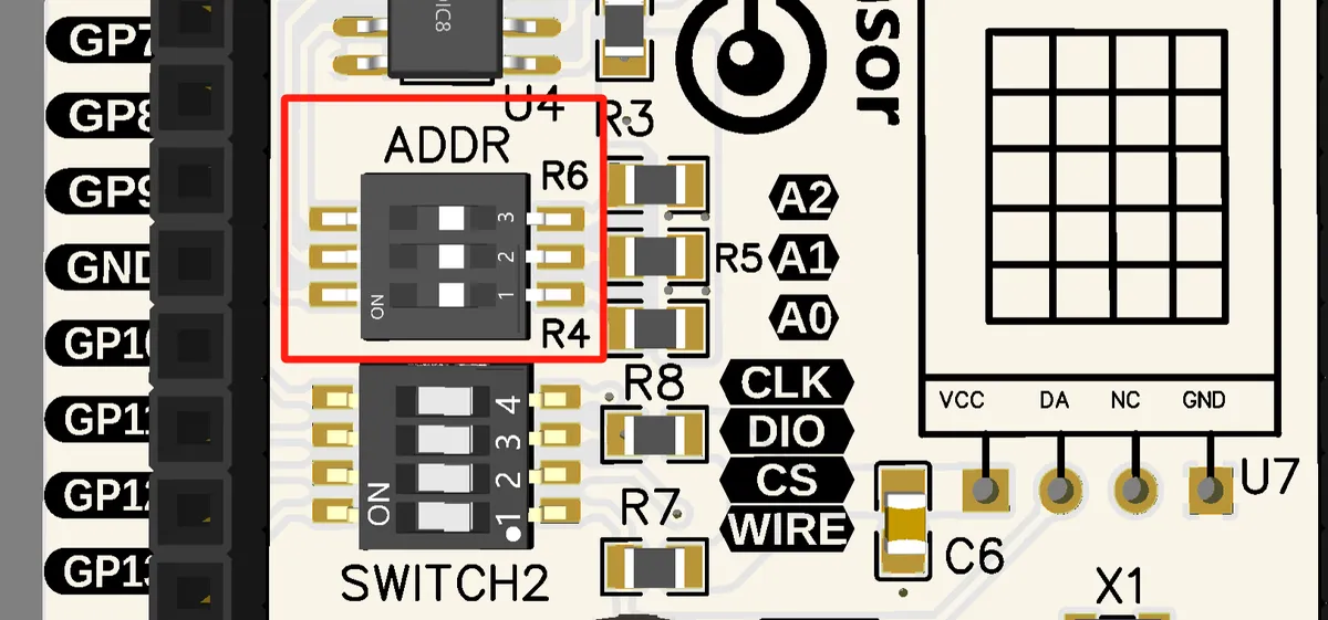
By default, the A2, A1 and A0 pins of the external EEPROM chip AT24C256 we use are all connected to GND (internal pull-down):
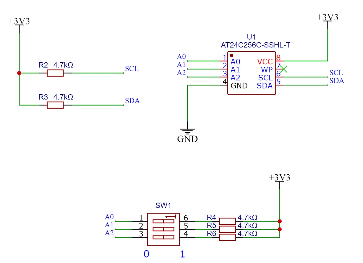
The device address is calculated as follows:
The connection between Raspberry Pi Pico and the external EEPROM module (AT24C256 chip) is shown in the following table:
device | Module Signals / Pins | Pico pins (GPIO) |
AT24C256 chip | SDA | GP2 |
AT24C256 chip | SCL | GP3 |
The sample code is as follows:
# Python env   : MicroPython v1.23.0
# -*- coding: utf-8 -*-
# @Time    : 2024/9/27 10:44 AM
# @Author  : Li Qingshui
# @File    : main.py
# @Description : I2C experiment: read and write the external EEPROM chip AT24C256

# ======================================== Import Modules =========================================

# Hardware-related modules
from machine import I2C, Pin
# Time-related modules
import time

# ======================================== Global Variables ============================================

# The AT24C256 chip address is 0x50, i.e. 0b1010000
# The upper 7 bits are the address bits and the lowest bit is the read/write control bit: 0 for write, 1 for read
AT24C256_ADDRESS = 0x50

# Define the number of bytes to write
DATA_SIZE = 128
# Generate a byte sequence from 0 to 127
data_to_write = bytes(range(DATA_SIZE))

# ======================================== Functions ============================================

def erase_data(at24cxx: 'AT24CXX', start_address: int, length: int) -> None:
    """
    Erase the data in the specified region to 0xFF.

    Args:
        at24cxx (AT24CXX): AT24CXX class instance.
        start_address (int): Start address.
        length (int): Erase length.

    Returns:
        None

    Raises:
        OSError: If the erase operation fails.
    """
    # Generate byte data of length `length`, with every byte set to 0xFF
    data_to_erase = bytes([0xFF] * length)
    # Write it continuously to the specified region
    at24cxx.write_page(start_address, data_to_erase)

# ======================================== Custom Classes ============================================

class AT24CXX:
    """
    AT24CXX class, used to operate AT24CXX series EEPROM chips over the I2C bus, supporting EEPROMs of multiple capacities.

    This class encapsulates I2C communication with the AT24CXX EEPROM and provides functions such as byte and page writing, reading, and erasing data.
    Supports EEPROM chips of different capacities (from 32KiB to 64KiB), reading and writing data over I2C.

    Attributes:
        i2c (I2C): I2C instance used to communicate with the AT24CXX chip.
        chip_size (int): Size of the EEPROM chip, default 64KiB.
        addr (int): I2C device address, default value is 0x50.
        max_address (int): Maximum accessible address of the device, depending on the size of the EEPROM.

    Methods:
        __init__(self, i2c, chip_size=AT24C512, addr=0x50):
            Initialize an AT24CXX class instance.

        write_byte(self, address: int, data: int) -> None:
            Write one byte to the specified address.

        read_byte(self, address: int) -> int:
            Read one byte from the specified address.

        write_page(self, address: int, data: bytes) -> None:
            Write one page of data to the specified address.

        read_sequence(self, start_address: int, length: int) -> bytes:
            Read data of the specified length sequentially.
    """

    # Different capacities of the AT24CXX series EEPROM
    AT24C32 = 4096      # 4KiB
    AT24C64 = 8192      # 8KiB
    AT24C128 = 16384    # 16KiB
    AT24C256 = 32768    # 32KiB
    AT24C512 = 65536    # 64KiB

    def __init__(self, i2c, chip_size: int = AT24C512, addr: int = 0x50) -> None:
        """
        Initialize an AT24CXX class instance.

        Args:
            i2c (I2C): I2C instance used to communicate with the AT24CXX chip.
            chip_size (int): Size of the EEPROM chip, default is AT24C512.
            addr (int): I2C device address, default is 0x50.

        Raises:
            ValueError: If the provided chip_size is not within the supported range.
        """
        # Check whether the EEPROM chip capacity is within the range defined by the AT24CXX class
        if chip_size not in [AT24CXX.AT24C32, AT24CXX.AT24C64, AT24CXX.AT24C128,
                             AT24CXX.AT24C256, AT24CXX.AT24C512]:
            raise ValueError("chip_size is not in the range of AT24CXX")

        self.i2c = i2c
        self.chip_size = chip_size
        self.addr = addr
        # Maximum address of the chip that the user can access
        self.max_address = chip_size - 1

    def write_byte(self, address: int, data: int) -> None:
        """
        Write one byte to the specified address.

        Args:
            address (int): Address to write to.
            data (int): Data to write, range 0-255.

        Raises:
            ValueError: If the address or data is out of the valid range.
        """
        # Check whether the address is within the valid range
        if address < 0 or address > self.max_address:
            raise ValueError('address is out of range')

        # Check whether the data is within the valid range
        if data < 0 or data > 255:
            raise ValueError("data must be 0-255")

        # Starting from the user-specified memory address `address`, write bytes([data]) to the EEPROM at device address addr
        # The memory address is 16 bits, two bytes
        self.i2c.writeto_mem(self.addr, address, bytes([data]), addrsize=16)
        # Delay 5 ms to wait for the EEPROM write to complete
        time.sleep_ms(5)

    def read_byte(self, address: int) -> int:
        """
        Read one byte from the specified address.

        Args:
            address (int): Address to read from.

        Returns:
            int: The data read.

        Raises:
            ValueError: If the address is out of the valid range.
        """
        # Check whether the address is within the valid range
        if address < 0 or address > self.max_address:
            raise ValueError("address is out of range")

        # Read one byte from the specified address
        value_read = self.i2c.readfrom_mem(self.addr, address, 1, addrsize=16)
        # Convert to an integer and return, using big-endian conversion
        return int.from_bytes(value_read, "big")

    def write_page(self, address: int, data: bytes) -> None:
        """
        Write one page of data to the specified address, handling page-crossing cases.

        Args:
            address (int): Starting address to write to.
            data (bytes): Data to write, with no limit on maximum length.

        Raises:
            ValueError: If the address, data length, or data is out of the valid range.
        """
        # Check whether the address is within the valid range
        if address < 0 or address > self.max_address:
            raise ValueError("address is out of range")

        # Check whether any data in the list is out of range
        for i in data:
            if i < 0 or i > 255:
                raise ValueError("data must be 0-255")

        # Check whether the length of data, combined with the starting address, is out of range
        if address + len(data) > self.max_address:
            raise ValueError("data exceeds maximum limit")

        # Get the boundary of the starting page
        page_boundary = (address // 64 + 1) * 64

        # Write the data in segments
        while data:
            # Calculate the number of bytes to write this time
            write_length = min(len(data), page_boundary - address)

            # Write one page of data to the specified address
            self.i2c.writeto_mem(self.addr, address, data[:write_length], addrsize=16)
            # Delay after writing to ensure completion
            time.sleep_ms(5)

            # Update the address and data
            address += write_length
            data = data[write_length:]

            # Update the page boundary
            page_boundary = (address // 64 + 1) * 64

            # If the current address exceeds the maximum address, stop writing
            if address > self.max_address:
                raise ValueError("address exceeds maximum limit")

    def read_sequence(self, start_address: int, length: int) -> bytes:
        """
        Read data of the specified length sequentially.

        Args:
            start_address (int): Starting address to read from.
            length (int): Number of bytes to read.

        Returns:
            bytes: The data read.

        Raises:
            ValueError: If the starting address and length are out of the valid range.
        """
        # Check whether the starting address and length are within the valid range
        if start_address < 0 or (start_address + length) > self.max_address:
            raise ValueError("address is out of range")

        # Read data of the specified length from the specified starting address
        return self.i2c.readfrom_mem(self.addr, start_address, length, addrsize=16)

# ======================================== Initialization ==========================================

# Power-on delay of 3 s
time.sleep(3)
# Print debug message
print("FreakStudio: Read and Write AT24C256")

# Create a hardware I2C instance using the I2C1 peripheral, with a clock frequency of 400KHz, SDA pin 2, and SCL pin 3
i2c_at24c256 = I2C(id=1, sda=Pin(2), scl=Pin(3), freq=400000)

# Start scanning for devices on the I2C bus and return a list of slave addresses
devices_list = i2c_at24c256.scan()
print('START I2C SCANNER')

# If devices_list is empty, no device is connected to the I2C bus
if len(devices_list) == 0:
    print("No i2c0 device !")
# If not empty, print the slave device addresses
else:
    print('i2c devices found:', len(devices_list))
    # Iterate over the slave device address list
    for device in devices_list:
        if device >= 0x50 and device <= 0x57:
            print("OLED hexadecimal address: ", hex(device))
            AT24C256_ADDRESS = device

# Create an AT24C256 instance
at24c256 = AT24CXX(i2c_at24c256, AT24CXX.AT24C256, AT24C256_ADDRESS)

# ========================================  Main Program  ===========================================

# Verify whether the single byte and the 128 bytes read have been retained after power-off
if at24c256.read_byte(0) == 0xAB and list(at24c256.read_sequence(1, DATA_SIZE)) == list(data_to_write):
    print("Data verification successful. Data retained after power cycle.")
    # Erase the data of the first three pages
    erase_data(at24c256, 0, DATA_SIZE + 1)
# Determine this is the first write experiment
else:
    # Erase the data of the first three pages
    print("Erase the data of the first three pages")
    erase_data(at24c256, 0, DATA_SIZE + 1)

    # Write a single byte: write 0xAB to address 0x00
    print("Writing single byte...")
    at24c256.write_byte(0x00, 0xAB)
    print("Written single byte 0xAB at address 0x00.")

    # Read a single byte: read the data at address 0x00
    print("Reading single byte...")
    single_byte = at24c256.read_byte(0x00)
    print(f"Read single byte: {single_byte:#04x}")

    # Write 128 bytes to address 0x01
    print("Writing 128 bytes...")
    at24c256.write_page(0x01, data_to_write)
    print("Written 128 bytes starting at address 0x01.")

    # Read 128 bytes, starting at address 0x01
    print("Reading 128 bytes...")
    read_data = at24c256.read_sequence(0x01, DATA_SIZE)
    print(f"Read 128 bytes: {list(read_data)}")
Here, we first created a class for controlling the read and write operations of AT24CXX series EEPROM chips AT24CXX, which supports EEPROMs of various capacities, allows users to perform byte-level and page-level read and write operations, and has the following methods:
write_byteMethod: Use thewriteto_memmethod to write a byte of data to the specified address, and delay for 5ms after writing to ensure that the EEPROM completes the write operation.read_byteMethod: Uses thereadfrom_memmethod to read a byte, and converts the read data into an integer before returning it.write_pageMethod: This method is used to write multiple bytes of data to a specified address and supports cross-page data writing. It mainly works by calculating the boundary of the current page, writing data in segments to ensure that each write does not exceed the page boundary, and adding a 5ms delay after writing the data of each page.read_sequenceMethod: sequentially reads data of a specified length, and uses thereadfrom_memmethod to read the data of the specified length and return a byte sequence.
In the main program, we performed the following operations:
- First, verify the power-off saving function: Check whether 0xAB has been written to address 0x00, and read the next 128 bytes of data to verify if it matches the generated byte sequence from 0 to 127. If the verification succeeds, print a success message and erase the data of the first three pages; if it fails, perform the initial write experiment.
- In the initial write experiment: erase the data of the first three pages, then write the single byte 0xAB to address 0x00, read and print this byte, finally write 128 bytes starting with 0x01 as the first byte, and sequentially read 128 bytes from address 0x01 and print the results
Burn the program, open the terminal, and the following content will be displayed:
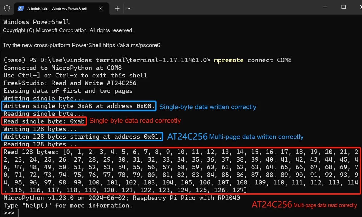
It can be seen that the customized AT24CXX class can implement the read and write functions for bytes and pages. Next, we unplug the data cable connected to the Raspberry Pi Pico to simulate a power-off scenario, then reconnect it, open the terminal to connect to the Raspberry Pi Pico, and the display is as follows:
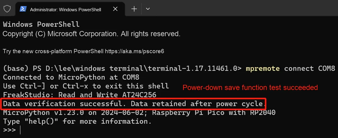
It can be seen that the data is still stored in the AT24C256 chip after power-off.
3.4 Application Experiment.mp4 19.3 MB
References
- Communication Protocol — Detailed Explanation of IIC
https://www.cnblogs.com/Ethan-Code/p/16783114.html
- Detailed Explanation of IIC Principles — Worth a Read
https://blog.csdn.net/as480133937/article/details/105366932
- Detailed Explanation of IIC (I2C), a Basic Communication Protocol
https://blog.csdn.net/qq_39829913/article/details/104718185
- Understanding I2C
https://medium.com/@shathiralakdilu/understanding-i2c-74b8f5304f2f
- I2C Communication Protocol
https://www.geeksforgeeks.org/i2c-communication-protocol/
- I2C
https://learn.sparkfun.com/tutorials/i2c/all
- Inter-Integrated Circuit (I2C) Protocol
https://docs.arduino.cc/learn/communication/wire/
- How to implement an I2C slave device with MicroPython I2C
https://blog.csdn.net/jd3096/article/details/128139728
- ESP8266 and ESP32 as an I2C slave in Micropython
https://www.az-delivery.de/en/blogs/azdelivery-blog-fur-arduino-und-raspberry-pi
- Use Pico as an I2C slave?
https://forums.raspberrypi.com/viewtopic.php?t=302978
- Master the I2C Protocol Thoroughly with These 16 Diagrams (Extremely Detailed)
https://blog.csdn.net/cy413026/article/details/133885798
- A Complete Guide to the I2C Bus (Part 1): What is I2C? What is a Bus? What is the I2C Bus? What is the I2C Standard? Features of the I2C Bus? Development History of the I2C Standard
https://www.cnblogs.com/deliweier-wangshuping/p/16167870.html
- Daisy Chain and Star Routing
https://blog.csdn.net/RichardLiTian/article/details/134186270
- The structure of daisy chain topology and its difference from star topology
https://www.elecfans.com/dianzichangshi/20171110577705.html
- MicroPython I2C Example: BME280 and OLED
https://electrocredible.com/micropython-i2c-code-tutorial-examples/
- MicroPython I2C Example: BME280 and MCP9808
https://learn.adafruit.com/micropython-hardware-i2c-devices/i2c-main
- Thorough Understanding of the I2C Bus (2): I2C Communication Protocol in Standard Mode, Fast Mode and Fast Mode Plus
https://www.cnblogs.com/deliweier-wangshuping/p/16228208.html
- Communication Protocol: Detailed Explanation of IIC
https://www.cnblogs.com/Ethan-Code/p/16783114.html
- Ultra-detailed Explanation of IIC Principles — Worth a Read + AT24C02
https://blog.csdn.net/as480133937/article/details/105366932
- W25Q128 AT24C256
https://forum.micropython.org/viewtopic.php?t=7593
- MicroPython I2C EEPROM driver
https://github.com/peterhinch/micropython_eeprom/blob/master/eeprom/i2c/I2C.md
- Interpretation of IIC Protocol for Synopsys DW_apb_i2c
https://blog.csdn.net/ptw1992/article/details/131413822
- Chapter 2 Introduction to DW_apb_i2c
https://blog.csdn.net/weixin_49259827/article/details/128222769
- MicroPython Hardware: I2C Devices MCP9808
https://learn.adafruit.com/micropython-hardware-i2c-devices/i2c-main
- MicroPython I2C Guide: Examples Using ESP32 & RPi Pico BME280
https://github.com/peterhinch/micropython_eeprom/blob/master/eeprom/i2c/I2C.md
- Raspberry Pi Pico: I2C Scanner (MicroPython) – Finding the Address of I2C Devices
https://randomnerdtutorials.com/raspberry-pi-pico-i2c-scanner-micropython/
- Master the OLED Display Principles: Get the Hang of Various Usage Methods of OLED Modules
- https://www.ebaina.com/articles/140000017194
- Detailed Introduction to SSD1306 OLED Driver Chip
- https://blog.csdn.net/qq_39829913/article/details/104716829
- 0.96-inch OLED (SSD1306) Screen Display (I) — Introduction to Basic Functions
- https://blog.csdn.net/qq_35953617/article/details/128154773
- micropython-ssd1306
- https://github.com/stlehmann/micropython-ssd1306/blob/master/ssd1306.py
- PyCharm MicroPython Multi-File Flashing:
- Flash multiple files to Micro:bit #62
https://github.com/JetBrains/intellij-micropython/issues/62
- Micropython Classes in separate Files
https://forum.micropython.org/viewtopic.php?t=12177
- Getting Started with the MicroPython in PyCharm for Raspberry Pi Pico.
https://community.element14.com/products/raspberry-pi/raspberrypi_projects/b/blog/posts/getting-started-with-the-micropython-in-pycharm-for-raspberry-pi-pico
- Interface OLED Graphic Display Module with Arduino
https://lastminuteengineers.com/oled-display-arduino-tutorial/
- micropython-pcf8575
https://github.com/mcauser/micropython-pcf8575
- PCF8575 Remote 16-bit I2C and SMBus I/O Expander with Interrupt Output
- 【Diao Ye Learns Programming】 Arduino Hands-On Project (116) --- 5-Way Navigation Key Module
https://makelog.dfrobot.com.cn/article-312854.html
- Explanation of Code and Principles for stm32-IIC/EEPROM (AT24C256)
https://blog.csdn.net/qq_52900974/article/details/128240268
- Read-write driver for microcontrollers for AT24C32, AT24C64, AT24C128, AT24C256, and AT24C512 series EEPROM chips
https://blog.csdn.net/wanglong3713/article/details/124909042
- micropython_eeprom/eeprom/i2c/eeprom_i2c.py
https://github.com/peterhinch/micropython_eeprom/blob/master/eeprom/i2c/eeprom_i2c.py
- mb_24x256_512/mb_24x256_512.py
https://github.com/MarksBench/mb_24x256_512/blob/main/mb_24x256_512.py
Chapter 15 Experiment of I2C Bus and AT24C256
https://rymcu.com/article/299
Version Record
Version Number | Modifier | Time | Content |
v1.0.0 | Li Zisheng | 2025/09/17 | Initialize the document, based on MicroPython version v1.23.0. To be added: I2C slave newly introduced in MicroPython v1.26.0. |
v1.1.0 | Li Zisheng | 2025/12/16 | The image has been modified successfully. Initialize the document, based on MicroPython version v1.23.0. To be added: I2C slave newly introduced in MicroPython v1.26.0. |
v1.1.1 | Li Zisheng | 2025/12/21 | Optimize some documents based on MicroPython version v1.23.0. To be added: I2C slave newly introduced in MicroPython v1.26.0. |