
Contents
- 1 Basic Concepts and Types of Interrupts
- 1.1 Basic Concepts of Interrupts
- 1.2 Types of Interrupts
- 1.3 NVIC Nested Vectored Interrupt Controller
- 2 NVIC Interrupt Controller on Raspberry Pi Pico
- 2.1 Interrupt
- 2.2 NVIC Controller
- 3. Software Control Method
- 3.1 Peripherals with Interrupt Function
- 3.2 Control Methods Related to Serial Port Interrupts
- 4. Application Experiment
- 4.1 Serial Port Interrupt Case
- References
- Version Record
1 Basic Concepts and Types of Interrupts
1.1 Basic Concepts of Interrupts
Here, we use an example to illustrate the concept and function of interrupts. Imagine the previous routine where we used a serial peripheral to receive data: we needed to constantly use the UART.any () method to check whether there is data available for reading from the outside. This approach works only when the code flow is simple and the number of peripheral calls is small. However, if we add code to the original program such as driving an LCD screen to display data, performing digital filtering on motion data, interacting with a PC via the USB protocol, and saving program runtime logs to external Flash, the program runtime will increase significantly. In the interval between two calls to the UART.any () method to obtain the serial port status, it is very likely that the gyroscope has already sent a large amount of data to the serial port, causing the serial port's FIFO memory to overflow.In this case, we need an interrupt. The function of the so-called interrupt is that once there is receivable data on the serial port peripheral, the preset interrupt callback function will be called to receive the data and perform corresponding processing.
Let's take another example where we previously used GPIO to read the press of an external key. The difference between the external interrupt method and the polling method is shown in the following figure:
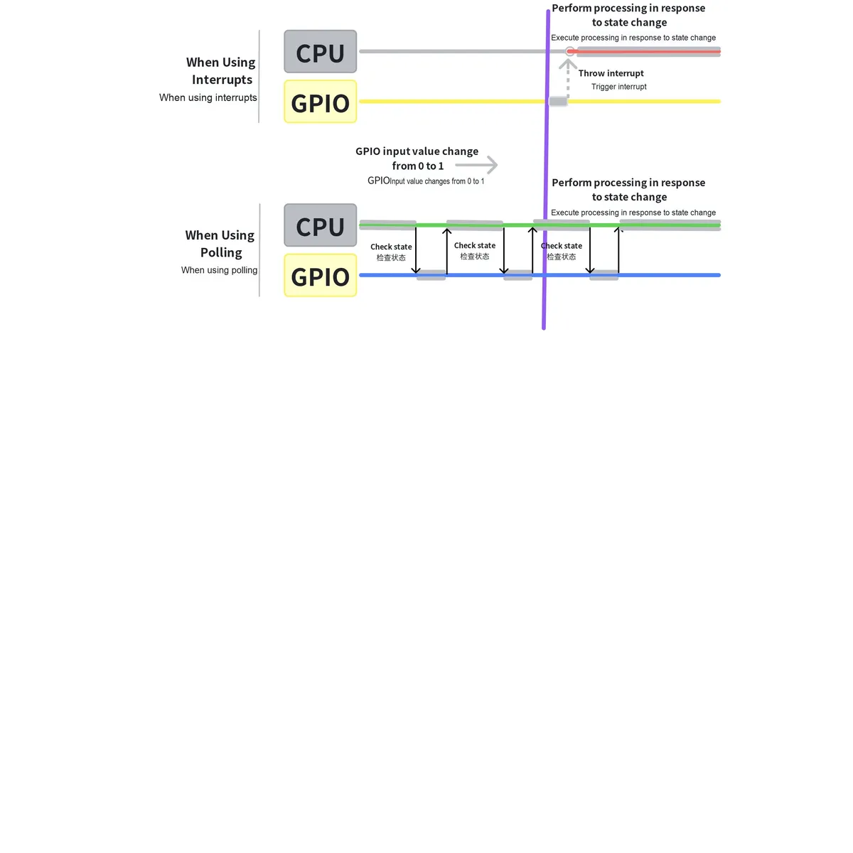
Extending the above example, we can obtain two different program execution modes: polling and interrupt.
- polling
Polling: If a program needs to wait for a specific state change to occur before executing a certain task, it periodically checks the state in a loop. It features simple programming and clear logic, but its drawbacks are that if the interval between two checks is too long, state changes occurring during the interval may be overlooked, and most of the checks are meaningless (state changes may only happen a few times over a long period, and the program state remains unchanged in most check scenarios). - Interrupt
Interrupts: Under this mechanism, once a state change occurs, an interrupt signal is triggered, which allows the CPU to immediately suspend the current task (while saving its current state), then switch to execute the interrupt-related handler routine, and resume the previous task state to continue execution after the processing is completed. This method not only improves the response speed of the system but also ensures the efficient utilization of resources.
Simply put, an interrupt is the core mechanism for an MCU to handle "sudden tasks" — for example, when a timer expires, data is received via a serial port, or a sensor triggers a signal, the MCU cannot wait until the core "finishes its current work" to process these events; instead, an interrupt will "interrupt" the core's ongoing operation to prioritize the urgent task. The NVIC (Nested Vectored Interrupt Controller) acts as the "interrupt scheduler" for each core, responsible for managing interrupt priorities and execution sequences.
1.2 Types of Interrupts
Interrupts can originate from inside the MCU or from external devices of the MCU. Simply put, they can be categorized into GPIO external interrupts, peripheral interrupts, and core interrupts:
- External Interrupt: It originates from the level change signal on the GPIO pin, and is triggered by an external device connected to the IRQ pin of the MCU. When a level change signal is generated (such as rising edge, falling edge, high/low level hold, corresponding to the GPIO interrupt trigger type explained earlier), the external interrupt controller of GPIO detects the interrupt signal, and then sends the corresponding interrupt signal to the NVIC interrupt vector controller.
- Peripheral Interrupt: An interrupt generated by on-chip peripherals (such as internal timers, SPI, UART, etc.). When the operating state of a peripheral changes (for example, when the UART detects that there is data available for reception), these interrupt signals are directly transmitted to the Nested Vectored Interrupt Controller (NVIC).
- Kernel Interrupt: A signal originating from inside the CPU, mainly including trap instructions, fault instructions and abort instructions, most of which are generated when the CPU encounters an error or a hardware fault during instruction execution.
IRQ and Priority
- IRQ: short for "Interrupt Request", is an "urgent call signal" sent by peripherals (such as timers and UARTs) to the processor core. When a peripheral needs the core to process a task immediately (for example, when a timer expires or data is received via a serial port), it triggers the corresponding IRQ, prompting the core to suspend its current work and prioritize handling this urgent task.
- Priority: refers to the sorting rule for the urgency of interrupt tasks. A chip may receive multiple IRQs at the same time, and tasks with higher priority will be processed first by the core to prevent urgent tasks from being delayed.
1.3 NVIC Nested Vectored Interrupt Controller
The main function of the NVIC (Nested Vectored Interrupt Controller) is to process interrupts, and it is responsible for managing the priority and execution sequence of interrupts:
- All interrupt requests from GPIOs, peripherals and the core must go through the unified coordination and distribution of the NVIC before they can be processed by the CPU.
- Just like the reception dispatcher of a company, all visiting clients (interrupt requests) must first go through the reception, which will arrange the corresponding employee (CPU) to receive them according to the urgency of the clients.
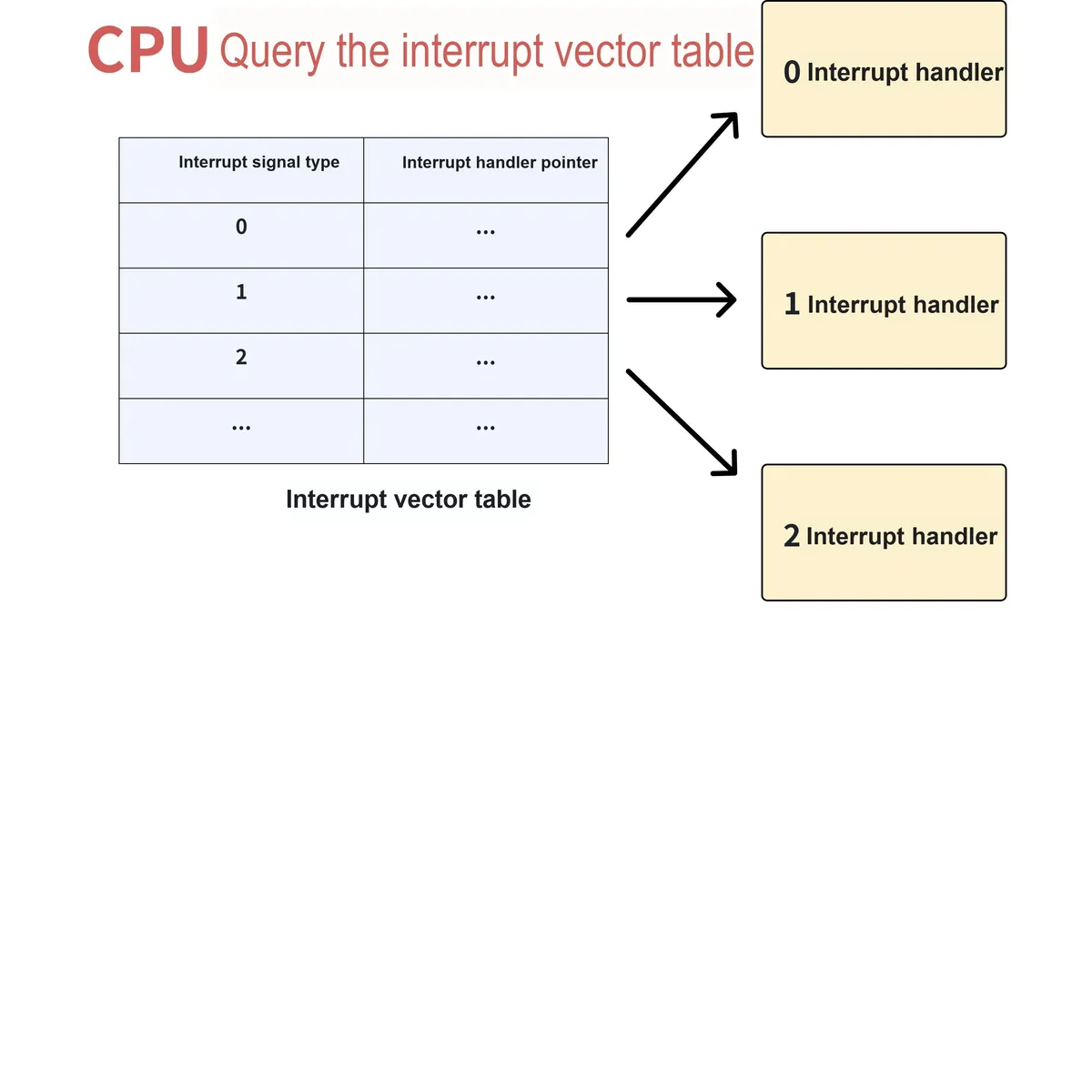
The NVIC contains an interrupt vector table, which serves as the "core navigation tool" for the CPU to process interrupts. Simply put, the interrupt vector table is a table arranged in ascending order of interrupt type numbers, where each entry corresponds to an interrupt type and stores the interrupt vector and the address of the corresponding Interrupt Service Routine (ISR) for that interrupt:
- An interrupt service routine is a program dedicated to handling that specific interrupt, and the address refers to the location of this program in memory;
- When an interrupt signal is received (for example, when there is data available to be received via UART), the CPU does not need to search for the handler one by one. Instead, it can directly find the corresponding program address in the interrupt vector table according to the interrupt type number, and immediately jump to the interrupt service routine for execution, which greatly improves the efficiency of interrupt processing.
The "nesting" feature of the NVIC is one of its core characteristics and the key that distinguishes it from ordinary interrupt controllers. The so-called "nesting" means that the NVIC allows users to set a priority level for each type of interrupt:
- When the CPU is handling a low-priority interrupt, if an interrupt request with a higher priority arrives at this moment, the NVIC will allow the higher-priority interrupt to "preempt" the control of the CPU, that is, suspend the processing of the current low-priority interrupt and prioritize the execution of the service routine for the higher-priority interrupt;
- After the higher-priority interrupt processing is completed, the CPU returns to the previously suspended low-priority interrupt and continues to finish the remaining processing tasks.
This process is called interrupt nesting. This mechanism ensures that the most urgent events in the system (such as hardware failures and important data reception) can be processed with priority, preventing urgent events from being delayed due to low-priority events occupying the CPU.
In addition, the NVIC also has the function of interrupt masking (disabling): it records which interrupts are set to the "masked state" by the user, and for these masked interrupts, the NVIC will directly ignore their requests and not pass them to the CPU. This is just like the front desk can refuse to receive customers on the blocklist, ensuring that the CPU will not be disturbed by unnecessary interrupts.
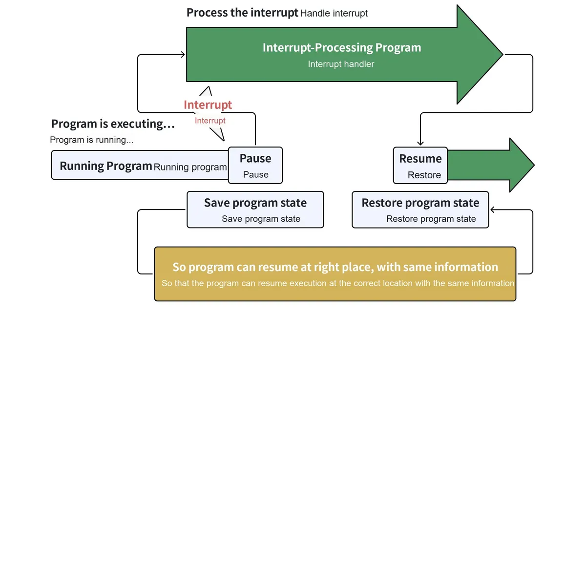
When an interrupt request is generated and scheduled by the NVIC, the CPU processes the interrupt in accordance with fixed steps. The entire process is analogous to a scenario where you are in the middle of writing a document when you suddenly receive an urgent email notification, and after handling the email, you return to the document to continue writing:
The fixed process is as follows:
- Normal program execution: The CPU originally executes the user's main program in sequence, and after completing each instruction, it actively checks whether the NVIC has any interrupt requests that need to be processed;
- Suspend the current program: When the CPU detects the interrupt signal transmitted by the NVIC, it will immediately stop executing the current main program;
- Save the program state: The CPU will automatically save key information such as the execution progress of the current main program and register data to ensure that it can accurately return to the interrupted position and continue execution subsequently;
- Find and execute the interrupt service routine: The CPU queries the interrupt vector table according to the type number of the interrupt signal, locates the address of the corresponding interrupt service routine, and then loads and executes this handler;
- Restore program state: After the execution of the interrupt service routine is completed, the CPU will automatically restore the previously saved state of the main program;
- Resume execution of the main program: The CPU returns to the point where it was interrupted and continues to execute the original main program.
After this processing is completed, the CPU automatically restores the saved information and resumes executing the program from where it stopped.
The following figure shows the state transition diagram when a user program switches to an interrupt service routine:
2 NVIC Interrupt Controller on Raspberry Pi Pico
2.1 Interrupt
Each core (Core0 and Core1) has an independent NVIC, which acts as a dedicated "interrupt dispatcher". It can receive 32 interrupt signals, but the RP2040 only uses the first 26 of them (IRQ0 to IRQ25), while the remaining IRQ26 to IRQ31 are reserved (they can also be forcibly triggered). When a peripheral (such as a timer or UART) triggers an urgent task, it sends a signal to the corresponding IRQ, and the NVIC then schedules the core to process it.
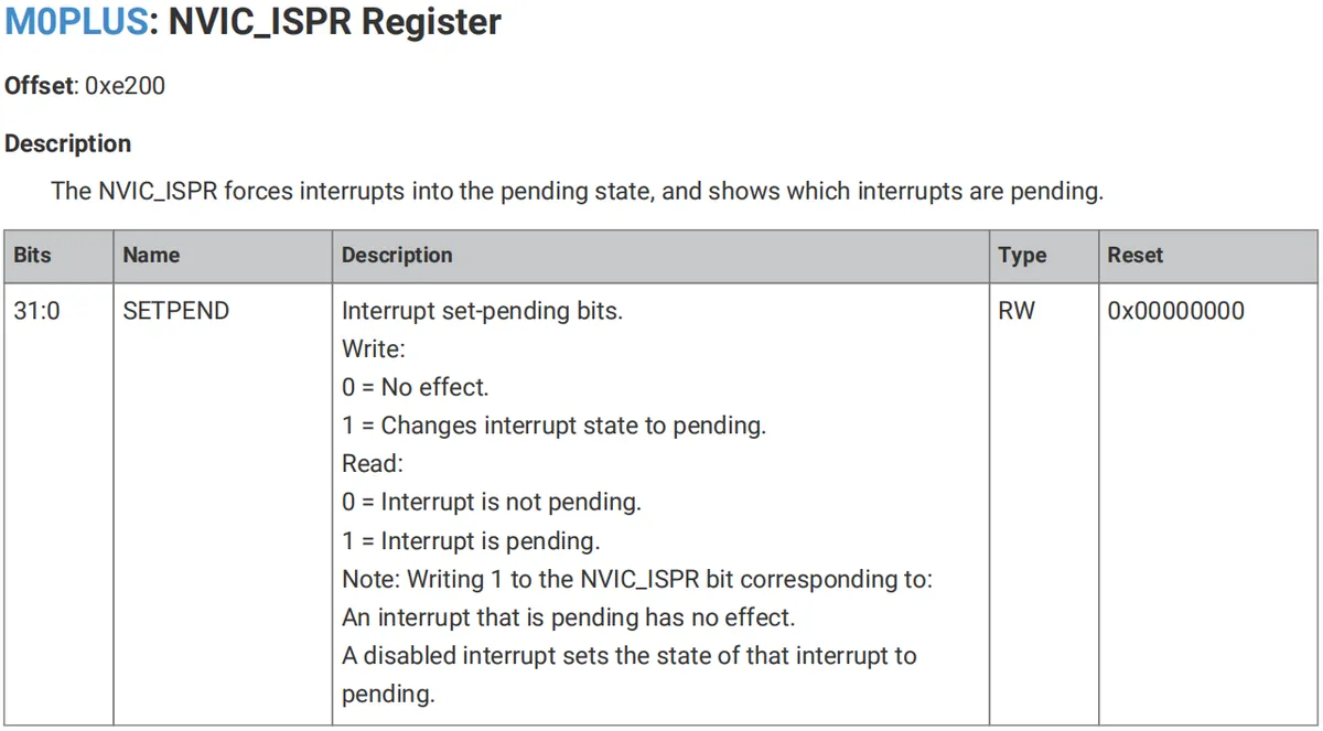
On the RP2040, only the lower 26 IRQ signals are connected to the NVIC, while IRQs 26 to 31 are not tied to any source. By writing to bits 26 to 31 in the NVIC ISPR register, the core can still be forced to enter the corresponding interrupt handler.
The interrupt vector table of the RP2040 is as follows. This table acts as a "task list for IRQs", where each IRQ number corresponds to a specific "source of urgent tasks":
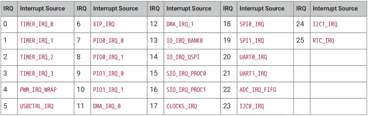
For example, IRQ0 corresponds to "IRQ of Timer 0"(meaning Timer 0 has timed out), and IRQ20 corresponds to "IRQ of UART0"(meaning UART0 has received data). Once the core sees the IRQ number, it can immediately identify which peripheral sent the "urgent call" and then invoke the corresponding handler.
The meanings of each interrupt are as follows:
| Interrupt name | Interrupt Meaning and Additional Notes |
| TIMER_IRQ_x (x=0~3) | Interrupts related to the general-purpose timers (x is 0-3, corresponding to the interrupts of the 4 general-purpose timers) |
| PWM_IRQ_WRAP | PWM timer wrap interrupt (triggered when the PWM counter reaches its maximum value and wraps around) |
| USBCTRL_IRQ | USB control interrupts (triggered by events such as USB peripheral state changes and data transfers) |
| XIP_IRQ | Interrupt related to the SSI synchronous serial interface controller; the signal comes from the SSI controller of the XIP cache for external flash, and can be used in configurations where code runs from SRAM instead of flash; once enabled, the XIP block can be used as a normal SSI peripheral |
| PIOx_IRQ_y (x=0/1, y=0/1) | Programmable IO interrupts (x is 0-1 for the 2 PIO blocks, y is 0-1 for the 2 interrupts of each PIO block) |
| DMA_IRQ_x (x=0/1) | DMA controller interrupts (x is 0-1 for the interrupts of the 2 DMA controllers) |
| IO_IRQ_BANK0 | General-purpose GPIO interrupts (triggered by level changes on the Pico's ordinary GPIO pins) |
| IO_IRQ_QSPI | Interrupts related to the QSPI peripheral GPIOs connected to external flash (triggered by events on the QSPI interface GPIO pins) |
| SIO_IRQ_PROCx (x=0/1) | Single-cycle low-latency IO interrupts (x is 0-1 for the SIO interrupts of the 2 CPU cores) |
| CLOCKS_IRQ | Clock system interrupts (triggered by events such as clock module state changes and frequency adjustments) |
| SPIx_IRQ (x=0/1) | SPI peripheral interrupts (x is 0-1 for the interrupts of the 2 SPI peripherals, such as receive complete and transmit complete) |
| UARTx_IRQ | Serial port interrupts (interrupts of the UART peripheral, such as receive complete, transmit complete, and communication errors) |
| ADC_IRQ_FIFO | Interrupts related to the FIFO memory of the ADC analog-to-digital converter (triggered by events such as the ADC FIFO buffer reaching a threshold or overflowing) |
| I2Cx_IRQ (x=0/1) | I2C serial communication bus interrupts (x is 0-1 for the interrupts of the 2 I2C peripherals, such as receive complete and transmit complete) |
| RTC_IRQ | RTC real-time clock interrupts (triggered by RTC timing events, alarms, etc.) |
Actually, interrupts can be further divided into the following two types: maskable interrupts (IRQ, Interrupt Request) and non-maskable interrupts (NMI, Non Maskable Interrupt), the core difference between which lies in "whether they can be selectively ignored by the CPU", as summarized in the table below:
| Feature | Maskable Interrupt (IRQ) | Non-Maskable Interrupt (NMI) |
| Core Definition | An interrupt that can be selectively ignored through software configuration (masking) | The highest-priority interrupt, which breaks through normal masking restrictions |
| Maskability | Can be completely masked by the CPU's interrupt mask bit; once masked, the CPU will not respond even if the interrupt occurs | Cannot be masked by normal means (the core meaning of the name); can only be configured in a limited way through dedicated registers |
| Trigger Scenarios | Routine peripheral events (such as UART data reception, GPIO button presses, timer timeouts) | Severe emergency events (such as hardware faults, power loss, coprocessor errors, core hardware exceptions) |
| Priority | Lower; multiple IRQs can be nested by setting priorities through the NVIC | Highest; can interrupt an IRQ being handled, and even the CPU's normal operation |
Simply put:
- Maskable interrupts (IRQs) are "routine-level" interrupts — for example, the notification alert when a WeChat message arrives on your phone (which you can block by enabling Do Not Disturb mode);
- A non-maskable interrupt (NMI) is an "urgent-level" interrupt, such as the alert triggered when a mobile phone detects that its battery is about to run out — this alert will pop up forcibly even if Do Not Disturb mode is enabled.
The 26 system interrupts of the Raspberry Pi Pico (such as TIMER_IRQ, UART_IRQ, GPIO_IRQ, etc.) will undergo two-step processing before being merged with kernel interrupts into a single NMI signal that is fed into the corresponding CPU core; the entire process can be understood as "interrupt filtering and merging":
- Step 1: Masking (selectively ignoring some system interrupts): First, 26 system interrupts go through masking processing — this is equivalent to setting a "do not disturb switch" for these interrupts. You can configure the mask register to select "which system interrupts to temporarily ignore even if they occur". For example, you can set "mask UART_IRQ", then even if the UART receives data, this interrupt will not enter the subsequent processing flow.
- Step 2: Perform an OR operation with the kernel interrupt to merge them into an NMI: After being masked, the remaining "non-ignored system interrupts" will undergo an OR operation with the CPU's internal kernel interrupts (such as more severe internal exceptions like power loss, coprocessor operation errors, and hardware faults) — if any one of these interrupts occurs, the result will be "interrupt present". Eventually, these scattered interrupt signals will be merged into a unified NMI signal and fed into the CPU core.
The core objective of this process is to: uniformly encapsulate all urgent events requiring the highest priority processing into NMI signals, so as to ensure that the CPU can respond to these critical events first.
NMIs are not absolutely unmaskable
Many beginners mistakenly assume that NMI stands for "interrupts that absolutely cannot be masked", but in reality, the true meaning of "Non-maskable" is that even when normal maskable interrupts (IRQs) are disabled, such NMI interrupts can still be delivered to the CPU.
In other words, the "non-maskable" property of NMI is relative to the masking of regular interrupts, and it is not absolutely impossible to configure: we can still perform limited configuration on the enablement of NMI signals through dedicated registers (this is a special configuration for NMI, which is different from regular interrupt masking).
The Raspberry Pi Pico provides dedicated configuration registers for the two CPU cores (Core0, Core1) respectively. These registers belong to the Syscfg register block (base address: 0x40000000) and are used to control the enabling of NMI signals:
- PROC0_NMI_MASK Register: Corresponds to Core0 core and is used to configure the NMI signal enable for Core0;
- PROC1_NMI_MASK register: corresponding to Core1 core, it is used to configure the NMI signal enable of Core1.
The core function of these two registers is to precisely control which merged NMI signals can actually be delivered to the corresponding core. For example, you can use the PROC0_NMI_MASK register to configure that "only NMI signals related to hardware faults are delivered to Core0, while other NMI signals are temporarily masked". This is a special configuration for NMIs and the only way to "filter" NMIs.
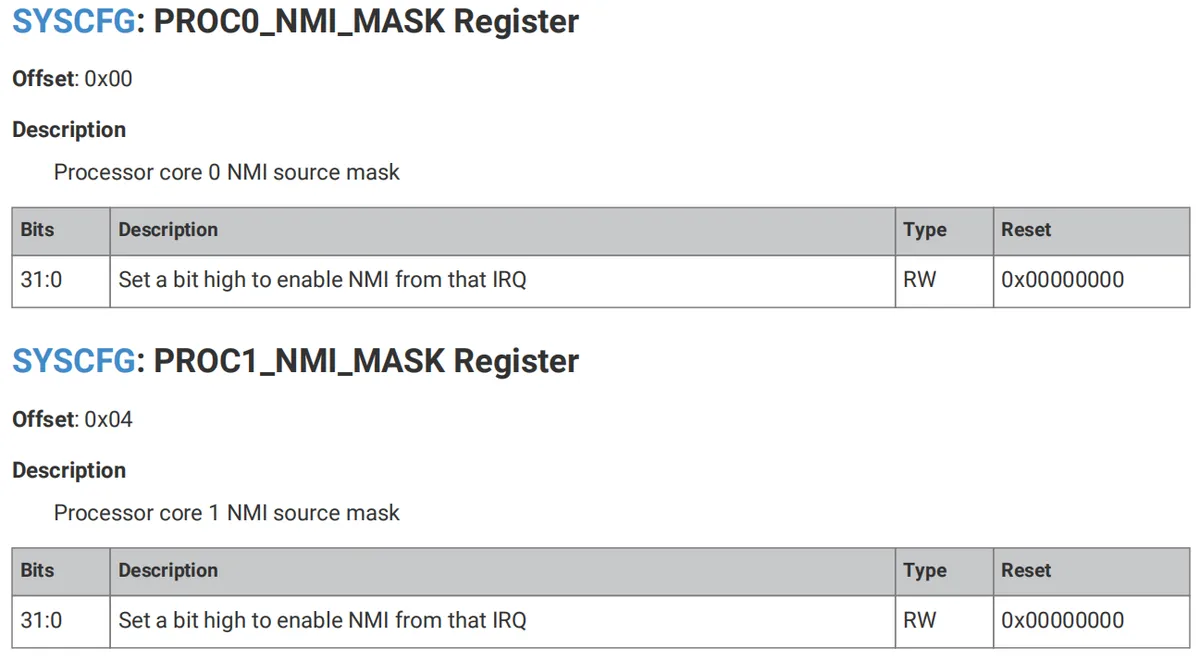
The bits [31:0](32 bits in total) of the two registers correspond one-to-one to the 32 system IRQs (interrupts) of the Raspberry Pi Pico:
- The
n-th bit (e. g., bit0, bit5) corresponds to "IRQn"(e. g., bit0 corresponds to IRQ0, bit5 corresponds to IRQ5). - Function of each bit: Setting a certain bit to 1 (high level) means "enable the IRQ corresponding to this bit as the NMI interrupt source of the current kernel"; setting it to 0 means "disable this IRQ as an NMI source".
Its operating characteristics include:
- Read-Write Permission (Type: RW): The current value of the register can be read via code, and its bit values can also be modified.
- Reset Value (Reset: 0x00000000): After the chip is powered on, all bits default to 0, which means by default no IRQ is configured as an NMI source, and manual configuration is required for it to take effect.
2.2 NVIC Controller
The base address of the registers related to the NVIC interrupt vector controller is PPB_BASE= 0xe0000000, which is a register set in the Raspberry Pi Pico that controls "internal peripherals that directly interact with the core". These internal peripherals (such as the SysTick timer and NVIC interrupt controller) are core components tightly coupled with the CPU core, and are responsible for basic functions such as core timing, interrupt scheduling, and memory protection.
Special attention: All registers under PPB_BASE can only be read and written in "word (32-bit)" mode (byte/half-word operations are not allowed), and are stored in "little-endian" format (i. e., the lower byte of the data is stored at the lower memory address).
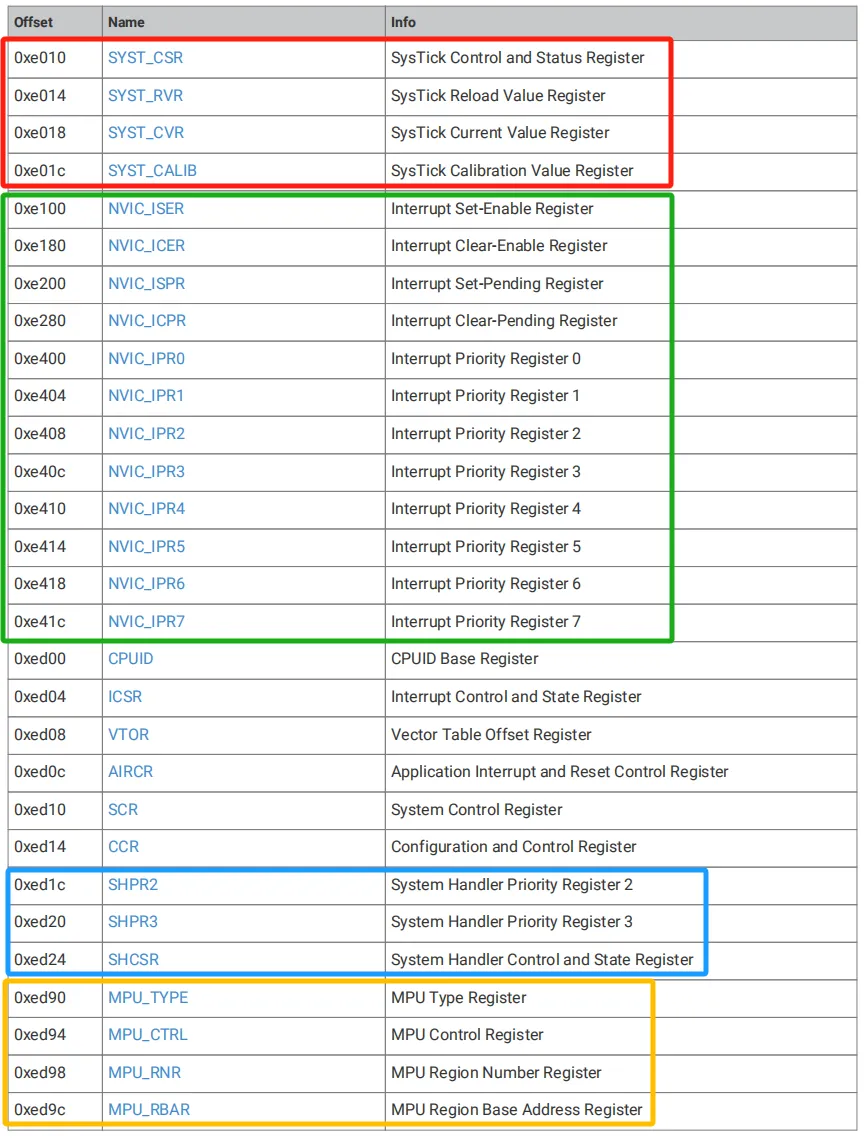
Wherein:
- The area within the red box contains the dedicated registers for
SysTick(System Tick Timer).SysTickis a basic timer built into the CPU core, which is commonly used to generate timer interrupts, implement delay functions, and for other similar purposes. - The key registers of
NVIC(Nested Vectored Interrupt Controller) are located within the green box, which correspond to the previously mentioned "interrupt dispatcher" function and are responsible for interrupt enabling, pending, and priority configuration. - The registers within the blue box belong to the system handler, which is responsible for managing the priority and status of "system-level interrupts"(such as
NMIand hard faults); - The registers in the yellow box belong to
MPU(Memory Protection Unit).The MPUis a component designed to "protect memory regions" — for example, preventing programs from illegally accessing a specific memory segment.
The NVIC of Raspberry Pi Pico interrupts supports nested interrupts in hardware: a low-priority interrupt can be preempted by a high-priority interrupt (or another exception such as a hard fault), and the low-priority interrupt will resume once the high-priority exception is completed.
When multiple IRQs are triggered simultaneously, the core processes them in sequence according to their "urgency level". The NVIC priority level of the RP2040 is defined by 2 bits, which corresponds to 4 types of NVIC interrupt configurations, and the priority is judged in two layers:

- NVIC dynamic priority: Each IRQ can be assigned 4 priority levels (0 to 3) via registers, where a smaller number indicates a higher urgency level (for example, level 0 is the highest priority and will be processed before level 1);
- IRQ Number Priority: If two IRQs have the same NVIC priority, the IRQ number will be the deciding factor — the smaller the number, the higher the urgency (for example, IRQ0 has a higher priority than IRQ1).
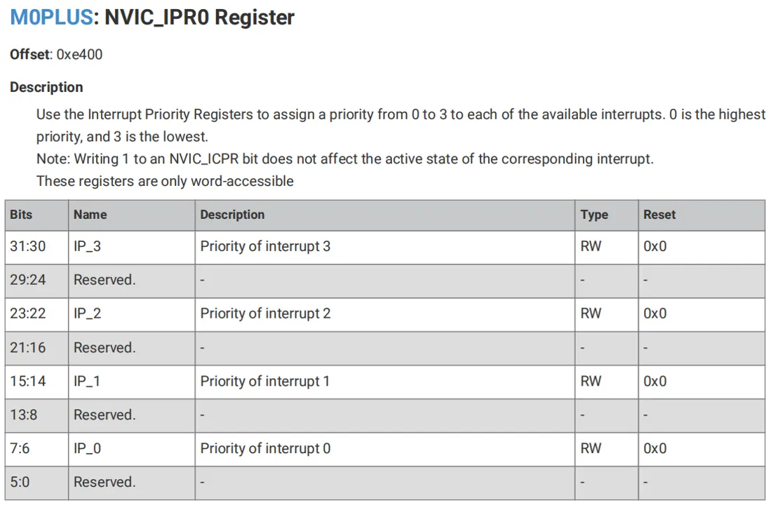
You can use the NVIC_IPRx Register (x = 0 to 7) to set a priority level ranging from 0 to 3 for each interrupt, where 0 represents the highest priority and 3 represents the lowest priority.
We can use the NVIC_ISER register to enable interrupts or check whether an interrupt is enabled. If an interrupt that is currently pending (i. e., a low-priority interrupt that has been preempted by a higher-priority interrupt) is enabled, the NVIC controller will activate the interrupt according to its priority. If an interrupt is not enabled, asserting its interrupt signal will set the interrupt to the pending state, but the NVIC will not activate the interrupt regardless of its priority.
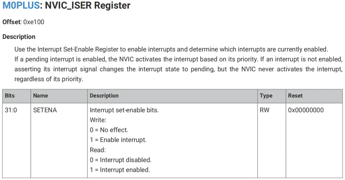
Similarly, we can disable interrupts or check whether an interrupt is disabled by means of the NVIC_ICER register.
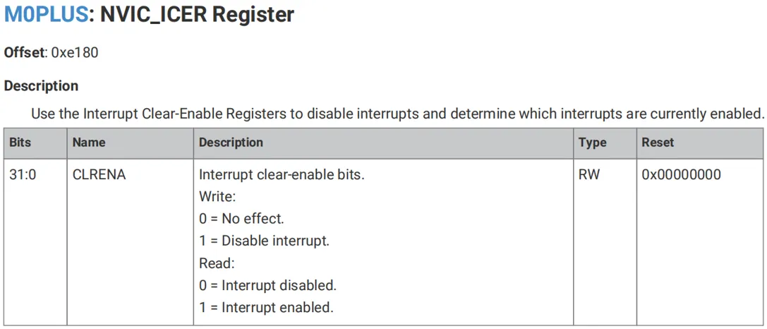
We can use the NVIC_ISPR register to force an interrupt into a pending state or check whether an interrupt is pending.
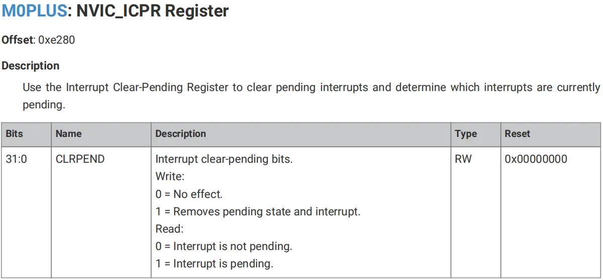
Similarly, we can use the NVIC_ICPR register to clear the pending status of an interrupt or check whether an interrupt is pending.
3. Software Control Method
3.1 Peripherals with Interrupt Function
In previous versions of MicroPython for the Raspberry Pi Pico (taking v1.23.0 as an example), only the following peripherals support interrupt functionality:
Peripheral | Description of the interrupt method |
Pin Class | External level changes can trigger GPIO external interrupts, and the interrupt callback function will be called once the interrupt is triggered. |
I2S Digital Audio Interface Category | An interrupt is triggered when the buffer (buf) object is filled or emptied, and the interrupt callback function is called after the interrupt is triggered. |
Real-Time Clock (RTC) Class | When the timer reaches the set time, an interrupt is triggered, and the interrupt callback function is called after the interrupt is triggered. |
Timer Class | Regularly execute the interrupt callback function; the system/hardware timer can be configured for periodic or one-shot callbacks (similar to a timed interrupt), Suitable for periodic tasks or timeout processing. |
Direct Memory Access (DMA) Class | An interrupt is triggered when DMA data transfer completes or a |
finite-state machine StateMachine class | Interrupts related to the finite-state machine can be triggered by a digital bit of 0 or 1, and an interrupt callback function will be called once the interrupt is triggered. |
It can be seen that MicroPython's SDK does not provide interrupt functions for other peripherals, such as interrupt reception for serial ports, but this does not mean that we cannot use other methods to replace polling (using while loop to call UART.any () to check whether there is data available for reception on the serial port). We can use methods such as timer-based regular serial port status query, multi-threading, and coroutines to complete the timely reception of serial port data more efficiently and accurately.
In the latest version of MicroPython for Raspberry Pi Pico (taking v1.26.0 as an example), interrupts for the newly added I2CTarget class and UART class are shown in the table below:
Peripheral | Description of the interrupt method |
I2CTarget Class | You can configure a Pico (or other board) as an I²C slave ( |
UART class | Interrupt triggering has been implemented on multiple ports (including rp2), and the supported trigger types include |
3.2 Control Methods Related to Serial Port Interrupts
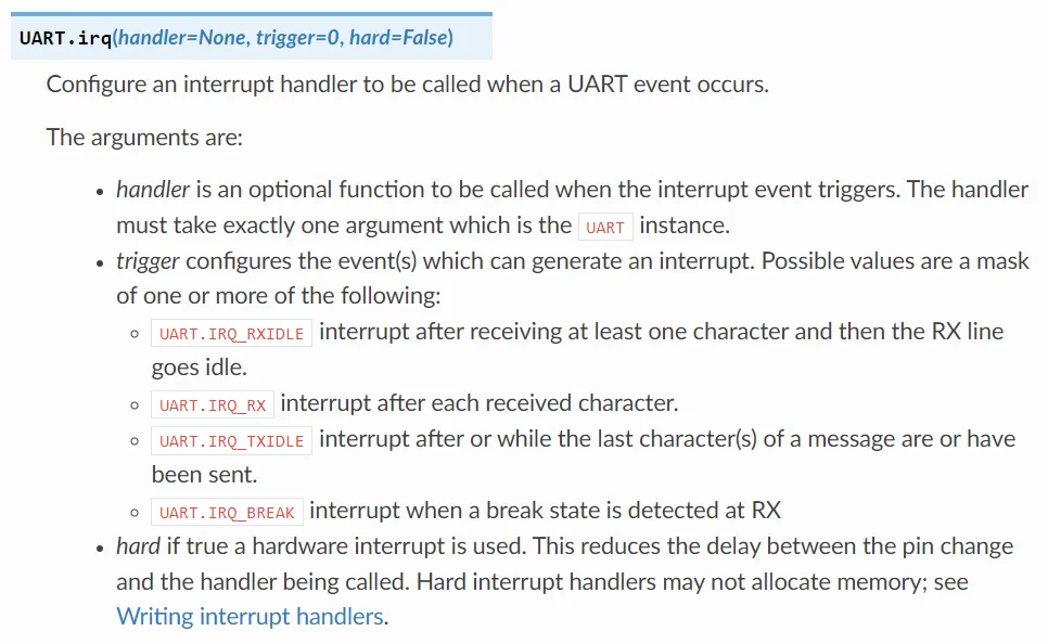
UART.irq () is the core method for configuring serial port interrupts on the Pico, which is used to bind an interrupt handling function to a specified UART instance (such as UART0/UART1). When a preset event (e. g., a character is received, the receive line is idle) occurs on the serial port, this function will be automatically executed, eliminating the need for the main program to perform polling on the serial port status and greatly improving the response efficiency of the serial port.
The official UART interrupt method is shown below:
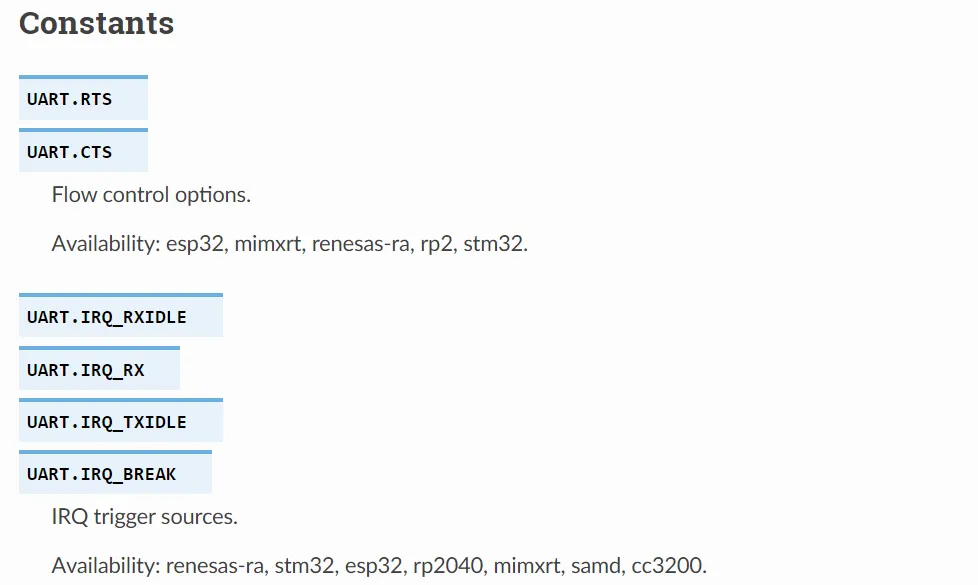
| Parameter | Meaning and Pico-specific notes | Additional notes |
|---|---|---|
| handler | Optional, interrupt handler function (takes only 1 argument, the UART instance that triggered the interrupt, such as UART0); set to None to disable the interrupt. ⚠️ Pico note: 1. When hard=True, the function must not allocate memory (such as print(), creating lists / string concatenation), otherwise the system crashes; 2. hard=False (default) is less restrictive, but it is recommended that the function only perform core operations (such as caching data). | |
| trigger | Interrupt trigger conditions (multiple conditions can be combined via ` | `), trigger sources and characteristics supported by Pico (RP2): 1. UART.IRQ_RXIDLE: triggers when the RX line is idle after receiving ≥1 character (suitable for processing complete data segments); 2. UART.IRQ_TXIDLE: triggers only when the sent message is longer than 5 characters, and 5 characters are still waiting to be sent when it triggers; 3. UART.IRQ_BREAK`: triggers when a Break state is detected on the RX line; after triggering, a valid character must be received before it can trigger again. |
| hard | Interrupt type: - False (default): soft interrupt (handled by the virtual machine, slightly higher latency, fewer restrictions); - True: hardware interrupt (driven directly by RP2040 hardware, extremely low latency, strict restrictions). ⚠️ Pico fully supports this parameter (unlike ESP32). |
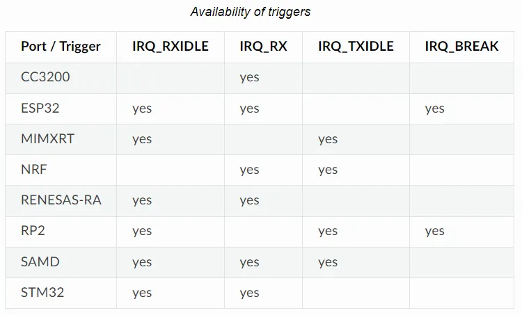
For the RP2040 corresponding to the Raspberry Pi Pico (the "RP2" row in the table), the UART interrupt trigger sources it supports are as follows:
IRQ_RXIDLE: Triggered when the RX line is idle after receiving ≥1 character (suitable for processing complete data segments);IRQ_TXIDLE: Triggered only when the length of the message to be sent is greater than 5 characters, and there are still 5 characters pending for transmission at the time of triggering;IRQ_BREAK: Triggered when a Break state on the RX line is detected; after triggering, a valid character must be received before it can be triggered again.
4. Application Experiment
4.1 Serial Port Interrupt Case
4.1.1 Preparations before the experiment
In the following experiment, we need to use the MiniUSB data cable to connect the Fengya No. 1 Board - Universal Compatible Expansion Board 's UART0 USB port to the USB port on the computer:
4.1.2 Receive Idle Interrupt (IRQ_RXIDLE): Receive Complete Data Frame
The UART receive idle interrupt (IRQ_RXIDLE) is a core interrupt mechanism for serial communication in MicroPython / embedded development. In simple terms: when the UART receive pin (RX) transitions from the busy state of "continuous data transmission" to the idle state of "no new bytes received within the specified duration", this interrupt will be triggered.Its core value lies in accurately identifying the completion of receiving "a complete frame of data/instructions" — it does not rely on a fixed frame length or end markers (such as \r\n), and only needs a pause (idle state) in data transmission to determine that the reception of one frame of data is completed. It perfectly solves the problem of "how to judge the end of variable-length instruction transmission", and is a common solution for parsing serial port instruction frames in scenarios such as the Internet of Things and industrial control.
Here, we periodically collect simulated temperature and humidity data in the code below, respond to specific commands via the UART idle interrupt and return the corresponding data; after the UART receives a command and triggers the idle interrupt, it parses the command and returns the environmental data (or a prompt for an unknown command), then resets the buffer.
The complete code is as follows:
# Python env   : MicroPython v1.27.0
# -*- coding: utf-8 -*-
# @Time    : 2025/12/28 10:37 AM
# @Author  : Li Qingshui
# @File    : main.py
# @Description : Serial receive idle interrupt (IRQ_RXIDLE): receive a complete command and return environment data

# ======================================== Import Modules =========================================

# Import MicroPython standard library modules
from machine import Pin, UART
# Import the time module
import time
# Used to simulate environment sensor data
import random

# ======================================== Global Variables ============================================

# Environment data cache (temperature + humidity)
env_data_cache = {"temp": 0.0, "humi": 0.0}
# Serial receive buffer (pre-allocated 128 bytes)
rx_buffer = bytearray(128)
# Buffer index
buf_index = 0

# ======================================== Functions ============================================

def uart_rxidle_handler(uart: UART) -> None:
    """
    Serial receive idle interrupt handler: reads a complete command and returns environment data.

    Args:
        uart (UART): The UART instance that triggered the interrupt (machine.UART type).

    Notes:
        - When the interrupt fires, read all unprocessed characters into the buffer to avoid data loss.
        - The maximum buffer length is limited to 64 bytes to prevent index overflow from causing program errors.
        - Only UTF-8 encoded commands can be parsed; non-UTF-8 characters may cause decoding to fail.
        - Recognizes the "GET_ENV_DATA" command and returns temperature and humidity data; other commands return an unknown-command message.
        - Reset the buffer index immediately after the command is parsed, so the next reception is not affected.
    """
    global buf_index, env_data_cache

    # Read all unprocessed characters into the buffer
    while uart.any() and buf_index < len(rx_buffer):
        rx_buffer[buf_index] = uart.read(1)[0]
        buf_index += 1

    # Parse the complete command
    if buf_index > 0:
        cmd = bytes(rx_buffer[:buf_index]).decode('utf-8').strip()
        # Respond to the environment data query command
        if cmd == "GET_ENV_DATA":
            resp = f"Env Data - Temp: {env_data_cache['temp']}C, Humidity: {env_data_cache['humi']}%\r\n"
            uart.write(resp)
        else:
            uart.write(f"Unknown command: {cmd}\r\n")
        # Reset the buffer
        buf_index = 0

def collect_env_data() -> tuple[float, float]:
    """
    Simulated environment sensor (temperature and humidity) data acquisition function (core business logic of the main task).

    Args:

    Notes:
        - The simulated temperature range is 18.0~35.0℃ and the simulated humidity range is 30.0~80.0%, kept to 2 decimal places.
        - After acquiring data, update the global environment data cache so the latest data is available when the interrupt responds to a command.
        - The return value is a tuple; the first element is the temperature (℃) and the second is the humidity (%).
        - Data acquisition has no hardware dependency and is used only to simulate business logic.
    """
    global env_data_cache

    temp = round(random.uniform(18.0, 35.0), 2)
    humi = round(random.uniform(30.0, 80.0), 2)
    # Update the global cache
    env_data_cache["temp"] = temp
    env_data_cache["humi"] = humi
    return temp, humi

# ======================================== Initialization ==========================================

# Power-on delay of 3 s
time.sleep(3)
# Print debug message
print("FreakStudio: Testing UART Recv IRQ_RX")

# Initialize the status LED (onboard Pin25) - indicates the data acquisition status
status_led = Pin(25, Pin.OUT)
status_led.off()

# Initialize UART0: TX=Pin0, RX=Pin1, baud rate 115200
uart0 = UART(0, baudrate=115200, tx=Pin(0), rx=Pin(1))
# Configure the serial interrupt: receive idle trigger (IRQ_RXIDLE), soft interrupt
uart0.irq(handler=uart_rxidle_handler, trigger=UART.IRQ_RXIDLE, hard=False)

# ========================================  Main Program  ============================================

# Main loop: core business logic (environment data acquisition) + wait for interrupt response
while True:
    # Real business task 1: acquire environment data
    current_temp, current_humi = collect_env_data()
    # Real business task 2: print the acquired data (debugging)
    print(f"Collected - Temp: {current_temp}°C, Humidity: {current_humi}%")
    # LED blinks to indicate the acquisition action
    status_led.on()
    time.sleep(0.1)
    status_led.off()
    # Simulated sensor acquisition interval
    time.sleep(1)
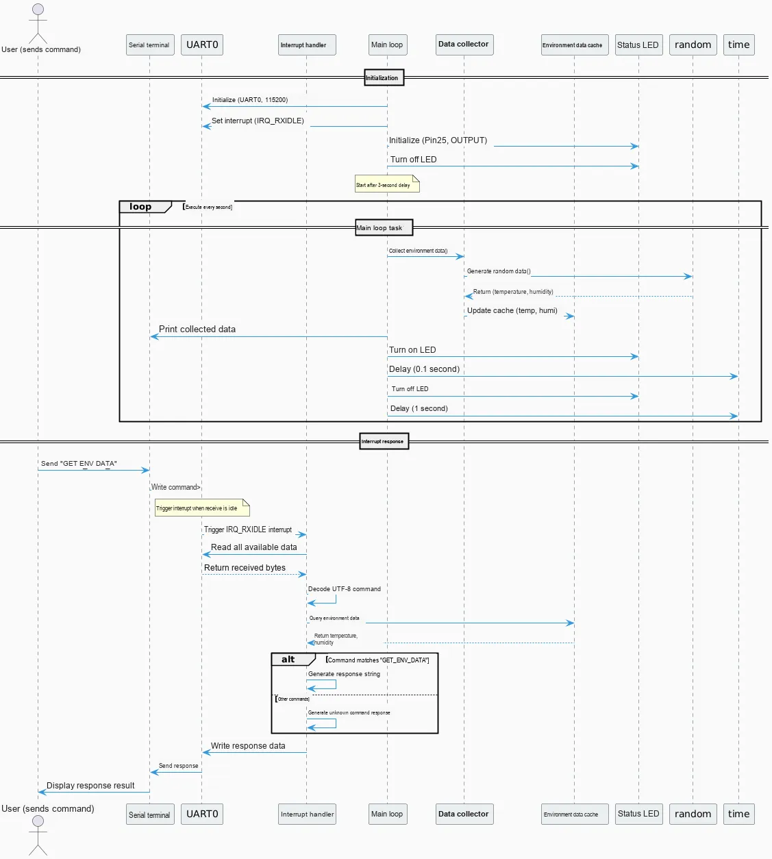
In the code above, we perform the following operations:
- Program startup and initialization;
- The program enters an infinite loop and repeatedly performs the following operations at a cycle of 1 second:
- Call
collect_env_datafunction to simulate environmental data collection: generate temperature data ranging from 18.0℃ to 35.0℃ and humidity data ranging from 30.0% to 80.0%(both retaining 2 decimal places), and update the globalenv_data_cachecache; - Print the currently collected temperature and humidity data (for debugging use), and control the status LED to turn on for 0.1 second then turn off (to visually indicate the Data Acquisition action);
- Delay for 1 second to simulate the actual sampling interval of the sensor, then repeat the above steps.
- Call
- When the serial port receives a complete command (triggering the "receive idle" interrupt), the main loop is paused and the interrupt processing logic is executed:
- Read all unprocessed characters from the serial port and store them in the pre-allocated 128-byte receive buffer (index restriction is applied to prevent out-of-bounds access);
- Decode the buffer data into a UTF-8 string, strip the leading and trailing whitespace, and parse the instruction content;
- Command Matching: If the command is "GET_ENV_DATA", return the latest temperature and humidity data in the cache via the serial port; for any other command, return the prompt "Unknown command";
- Reset the buffer index, the interrupt handling is completed, and the program returns to the main loop to continue executing the Data Acquisition task.
The following is the overall flow chart:
Open the XCOM software and select the COM port corresponding to the CH340K chip:
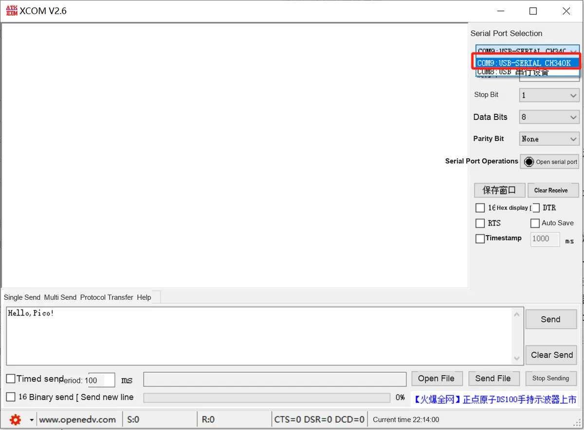
The serial communication parameters are consistent with those in the program:
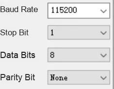
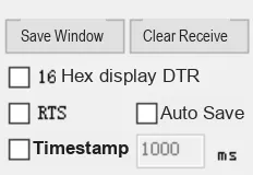
All other sending and receiving parameters can be left as default.
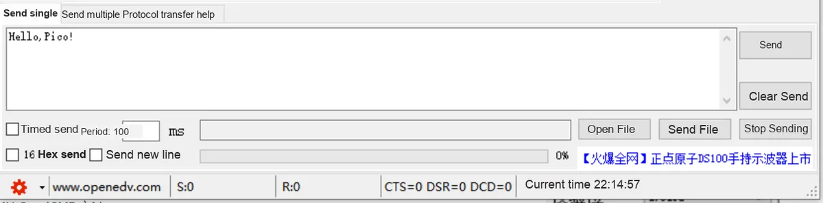
Click to open the serial port:
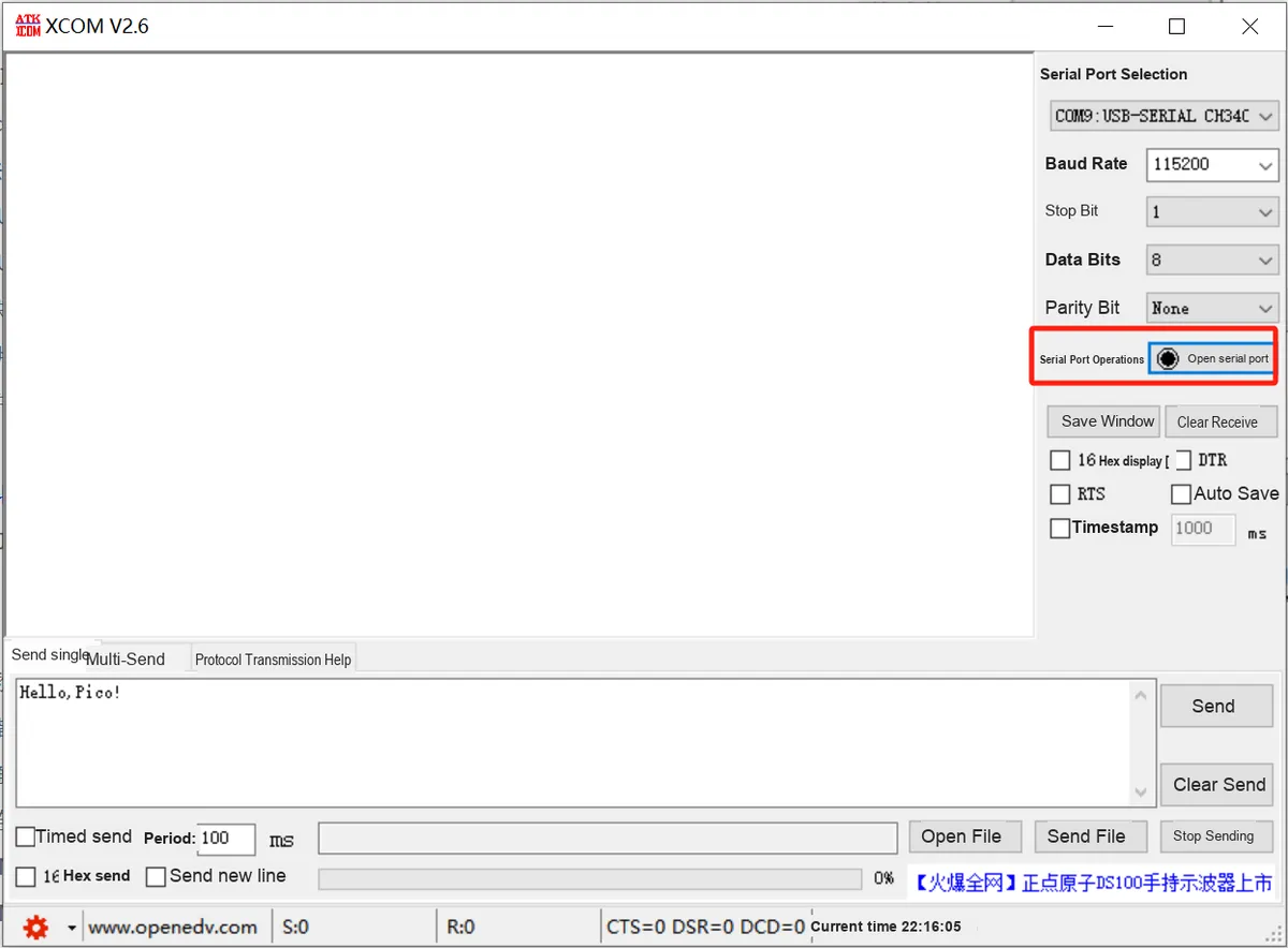
Burn the program, open the terminal, and the following content will be displayed:
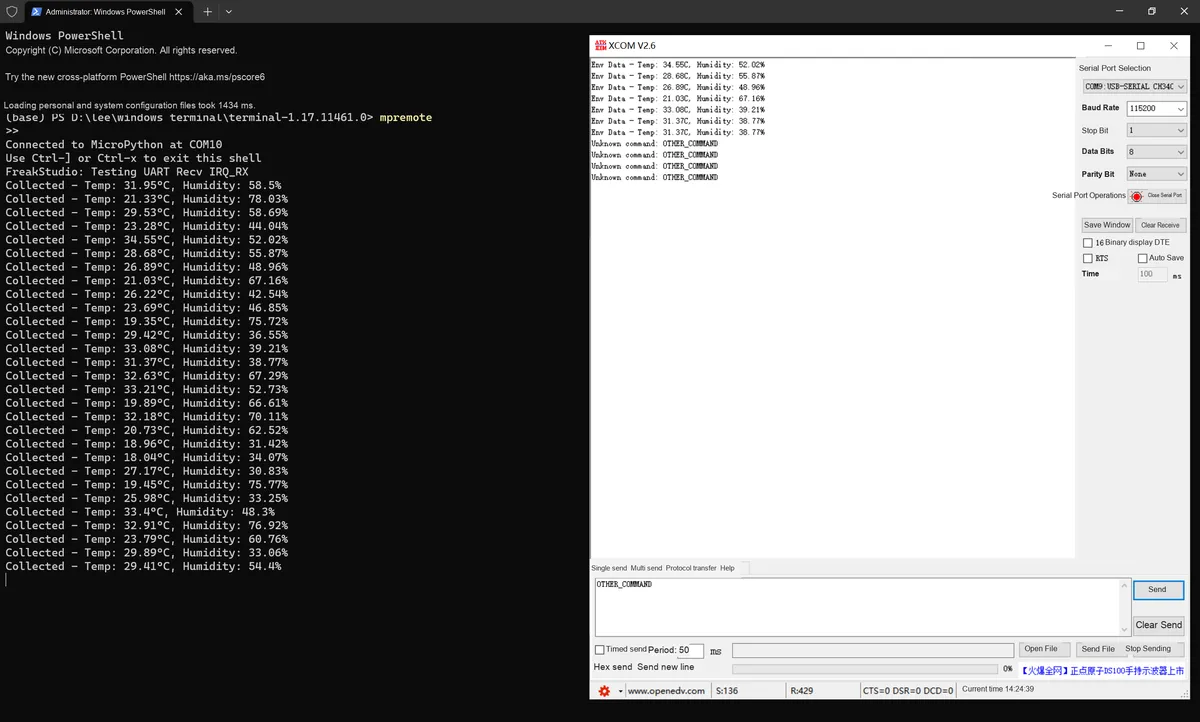
As can be seen, the LED on the core board flashes periodically, and the serial command response function also works as expected (sending GET_ENV_DATA returns the corresponding temperature and humidity data, while sending OTHER_COMMAND triggers an "unknown command" prompt), indicating that the overall function operates properly.
4.1.3 Transmit Idle Interrupt (IRQ_TXIDLE): Confirm Completion of Long Data Transmission
The UART transmission idle interrupt (IRQ_TXIDLE) is a core interrupt mechanism for the data transmission link in UART communication. Specifically, it is triggered when the UART transmitter (TX) has completely sent all bytes to be transmitted in the transmit buffer, the transmit buffer is empty, and the TX pin enters the idle state with no data output.Its core value lies in accurately confirming that "the transmission process of a long data block / a complete frame of data has been thoroughly completed", rather than merely triggering the transmission action. It is especially suitable for scenarios that require transmitting large-size data (such as batch sensor logs, long text responses, and binary data streams), and can effectively prevent data loss or disorder caused by modifying the buffer, closing the serial port, or initiating the next transmission before the completion of the current transmission is confirmed.
It corresponds to the receive idle interrupt (IRQ_RXIDLE):
IRQ_RXIDLEFocus on the scenario where "the complete data frame has been received";IRQ_TXIDLEFocus on the event that "the complete data frame has been fully transmitted".
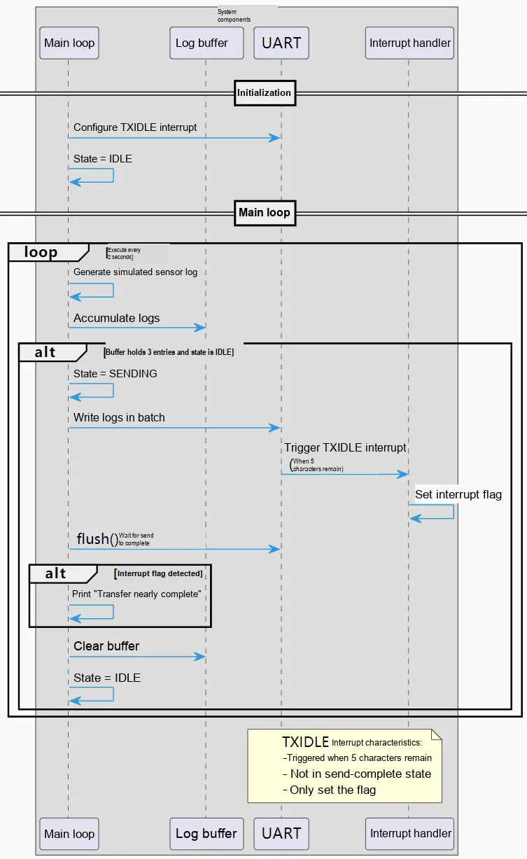
In the following code, we use the IRQ_TXIDLE interrupt flag, which indicates that the long log transmission is nearly complete, combined with the batch caching mechanism to implement reliable serial transmission of simulated sensor logs.
The complete code is as follows:
# Python env   : MicroPython v1.27.0
# -*- coding: utf-8 -*-
# @Time    : 2025/12/28 11:12 AM
# @Author  : Li Qingshui
# @File    : main.py
# @Description : Serial transmit idle interrupt (IRQ_TXIDLE) - long log transmission status prompt

# ======================================== Import Modules =========================================

# Import MicroPython standard library modules
from machine import Pin, UART
# Import the time module
import time
# Used to simulate sensor data
import random

# ======================================== Global Variables ============================================

# Sensor log cache (send after accumulating 6 entries, ensuring length > 5 to trigger TXIDLE)
sensor_logs = []
# Log number
log_seq = 1
# Send state: IDLE (idle) / SENDING (sending)
tx_status = "IDLE"
# TXIDLE interrupt trigger flag
txidle_flag = False

# ======================================== Functions ============================================

def uart_txidle_handler(uart: UART) -> None:
    """
    RP2 serial TXIDLE interrupt handler (soft interrupt); only marks the interrupt trigger state to avoid hardware preemption.

    Args:
        uart (UART): The UART instance that triggered the interrupt (machine.UART type).

    Notes:
        - The RP2 TXIDLE interrupt fires when 5 characters remain to be sent, not when transmission is complete.
        - Mark only in the sending (SENDING) state, to avoid spurious triggers disturbing the state machine.
        - Do not perform UART write operations, to prevent hardware preemption from corrupting data.
    """
    global txidle_flag
    # Mark only while sending
    if tx_status == "SENDING":
        txidle_flag = True

def generate_sensor_log() -> str:
    """
    Generate a fixed-format simulated sensor log, adapted to the RP2 UART buffer characteristics.

    Args:
        None

    Notes:
        - A fixed field format ensures every log entry has the same number of characters, avoiding data truncation caused by length fluctuation.
        - The log number is zero-padded to 4 digits, to prevent visual confusion from the number cycling too quickly.
        - Reset the number when it exceeds 9999, to prevent numeric overflow from affecting log readability.

    Return:
        (str): Simulated sensor log file, fixed format.
    """
    global log_seq

    temp = round(random.uniform(20.0, 40.0), 2)
    pressure = round(random.uniform(950.0, 1050.0), 2)
    # Force a fixed format so every log entry has the same length (avoids truncation)
    log = f"LOG_{log_seq:02d} | Time: {int(time.time())}s | Temp: {temp:5.2f} degC | Pressure: {pressure:6.2f} hPa"
    log_seq += 1
    return log

def send_log_batch(uart: UART) -> None:
    """
    RP2 serial batch send function for 3 log entries, adapted to the hardware FIFO buffer capacity (prevents truncation).

    Args:
        uart (UART): The UART instance used to send logs (machine.UART type).

    Notes:
        - The batch threshold is set to 3 entries, and the total character count fits the RP2 UART FIFO buffer, avoiding data backlog.
        - Use uart.flush() to block and wait, replacing the unreliable uart.txdone(), to ensure sending is complete.
        - Send only in the IDLE state, to avoid multithread-like state races that corrupt data.
        - Write the whole batch of logs at once, to guarantee an atomic send operation at the hardware level.

    Return:
        None
    """
    global sensor_logs, tx_status, txidle_flag

    if len(sensor_logs) >= 3 and tx_status == "IDLE":
        tx_status = "SENDING"

        # Reset the interrupt flag
        txidle_flag = False

        # Concatenate the whole batch of logs (atomic block, sent at once)
        long_log = "\r\n".join(sensor_logs) + "\r\n===== LOG BATCH END =====\r\n"
        print(f"Sending {len(sensor_logs)} logs...")

        # Write the whole batch of logs at once (hardware atomic operation)
        uart.write(long_log)

        # Block until the whole batch of logs is sent
        while uart.flush():
            time.sleep_ms(5)

        # After sending completes, output the TXIDLE prompt to the terminal
        if txidle_flag:
            print("[STATUS] Transmission nearly complete (TXIDLE triggered)")
            txidle_flag = False

        # Clear the cache + restore the state
        sensor_logs.clear()
        tx_status = "IDLE"

# ======================================== Initialization ==========================================

# Power-on delay of 3 s
time.sleep(3)
# Print debug message
print("FreakStudio: Testing UART Transmit IRQ_TXIDLE")

# Initialize the send status LED (onboard Pin25)
tx_led = Pin(25, Pin.OUT)
tx_led.off()

# Initialize UART0: TX=Pin0, RX=Pin1, baud rate 115200
uart0 = UART(0, baudrate=115200, tx=Pin(0), rx=Pin(1))
# Configure the serial interrupt: transmit idle trigger (IRQ_TXIDLE), soft interrupt
uart0.irq(handler=uart_txidle_handler, trigger=UART.IRQ_TXIDLE, hard=False)

# ========================================  Main Program  ============================================

while True:
    # Generate logs only when idle (avoids buffer overload)
    if tx_status == "IDLE":
        log = generate_sensor_log()
        sensor_logs.append(log)
        print(f"Generated: {log}")

    # Batch send (blocks until complete)
    send_log_batch(uart0)

    # Update the LED and print the status
    tx_led.value(1 if tx_status != "IDLE" else 0)
    print(f"Transmit Status: {tx_status}")

    # Fixed interval (lower the loop frequency to reduce conflicts)
    time.sleep(2)
In the code above, we have completed the following tasks:
- Program startup and initialization;
- The program enters an infinite loop and repeatedly performs the following operations at a cycle of 2 seconds:
- Log generation: This function is called only when the transmission status (tx_status) is IDLE
generate_sensor_logto generate a simulated temperature and pressure sensor log in a fixed format (including log ID, timestamp, temperature, and barometric pressure), add the log to the cache listsensor_logsand print the generation information; - Batch sending: call the
send_log_batchfunction. If the number of cached logs ≥ 3 and the system is in IDLE state, execute the batch sending logic:- Switch tx_status to SENDING and reset the TXIDLE interrupt flag
txidle_flag; - Stitch the 3 logs in the cache into a complete long text (with the "LOG BATCH END" end marker), and write and send it all at once via UART0 (to ensure hardware atomic operations and avoid data truncation);
- Call
uart.flush ()to block and wait until all data is sent (it checks once every 5ms during this period, replacing the unreliableuart.txdone ()); - If the TXIDLE interrupt is triggered (
txidle_flagis True), print the prompt "Transmission is nearly complete" and reset the flag; - Clear the log cache and restore tx_status to IDLE;
- Switch tx_status to SENDING and reset the TXIDLE interrupt flag
- Status indication: Control the LED according to tx_status (light up when SENDING, turn off when IDLE), and print the current transmission status;
- Delay for 2 seconds: reduce the loop frequency, cut down transmission conflicts, and adapt to the characteristics of the hardware buffer.
- Log generation: This function is called only when the transmission status (tx_status) is IDLE
TXIDLEInterrupt Response: When the UART0 transmit buffer has 5 remaining characters to be transmitted (a RP2 hardware feature) and triggers the IRQ_TXIDLE interrupt, execute theuart_txidle_handlerfunction: only when tx_status is SENDING, marktxidle_flagas True (only mark the status without performing write operations to avoid data corruption caused by hardware preemption), for the main loop to determine the status that transmission is nearing completion.
The complete flow chart is as follows:
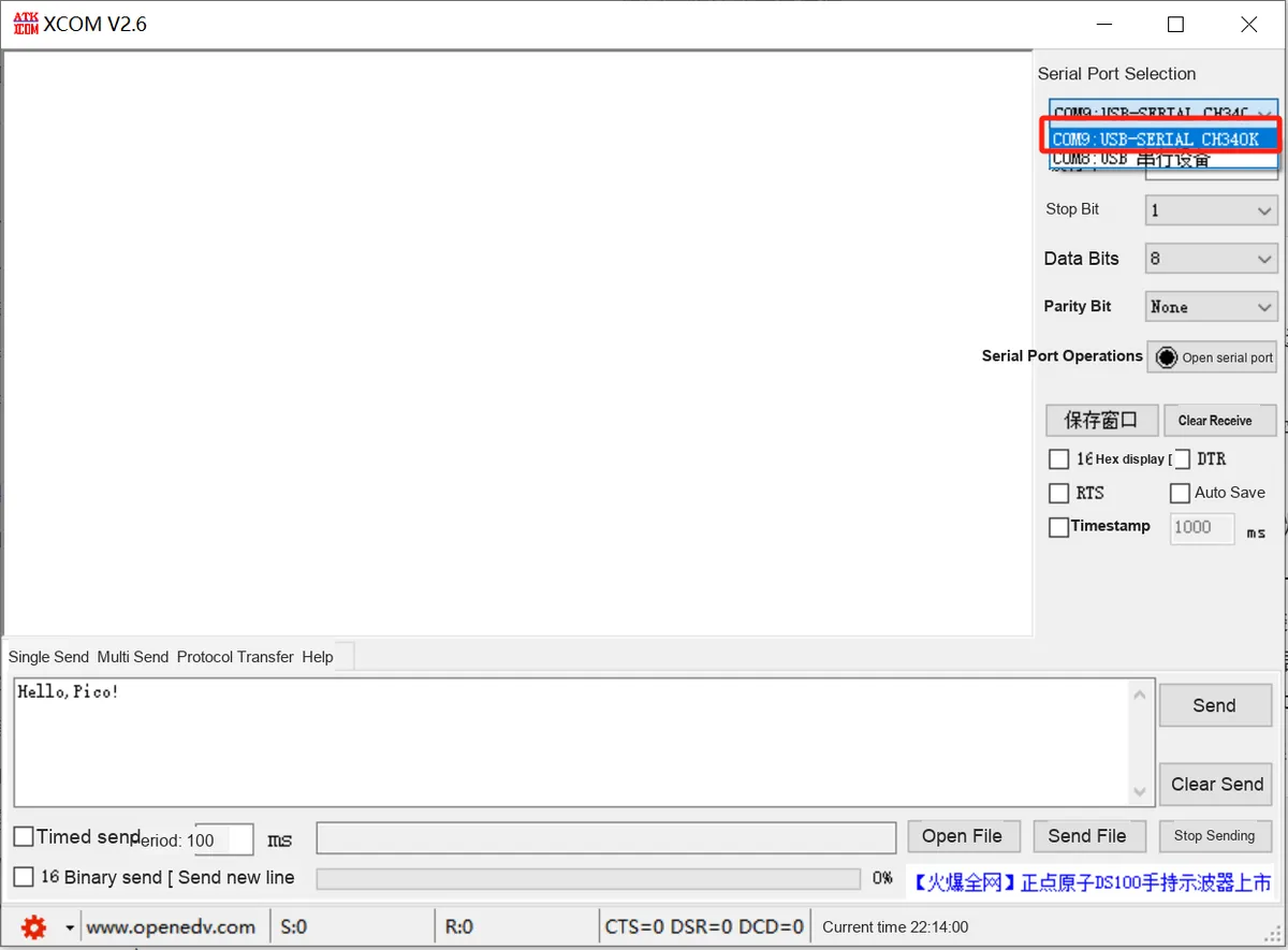
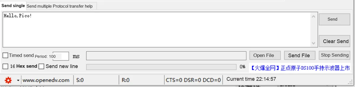
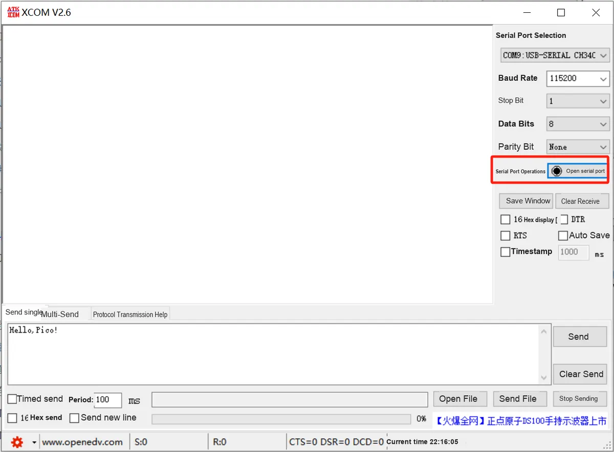
Open the XCOM software and select the COM port corresponding to the CH340K chip:
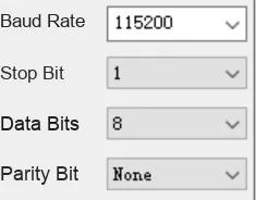
The serial communication parameters are consistent with those in the program:
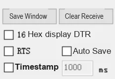
All other sending and receiving parameters can be left as default.
Click to open the serial port:
Burn the program, open the terminal, and the following content will be displayed:
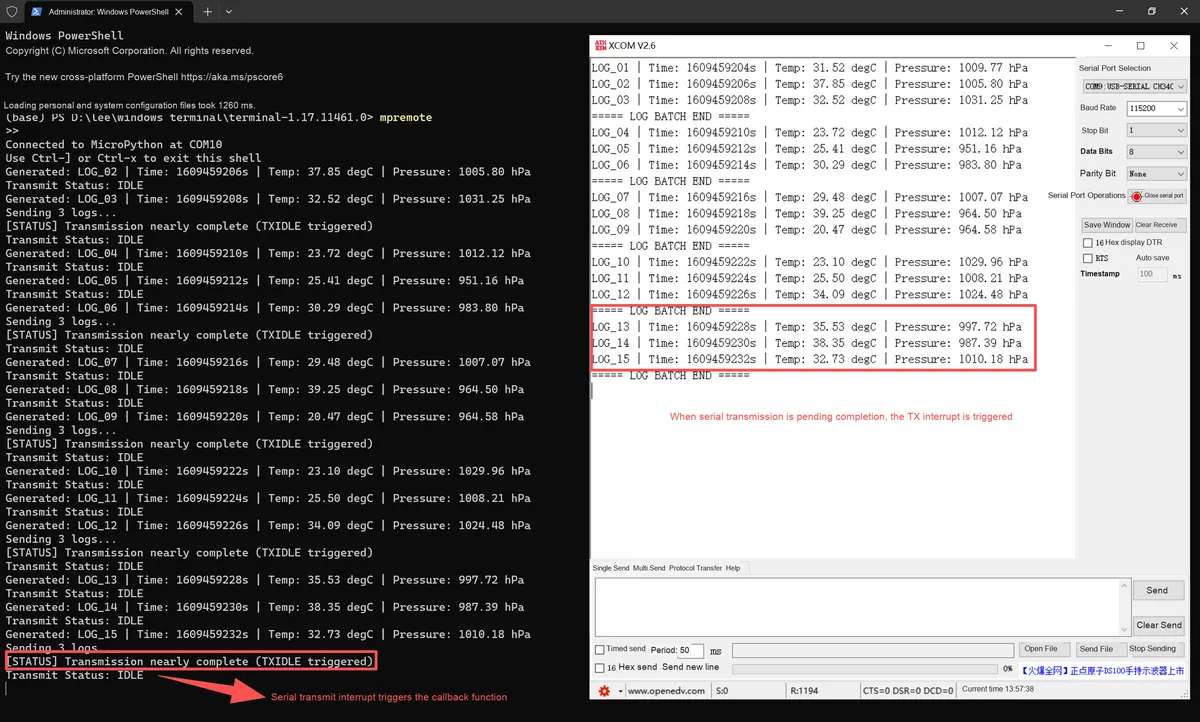
We can see that the running effect of the program fully meets the expectations:
- The main loop periodically generates simulated sensor logs in a fixed format (the terminal on the left continuously outputs the log information corresponding to "Generated"), and automatically enters the sending state when the log cache accumulates to 3 entries (the terminal displays "Sending 3 logs");
- During the transmission process, the IRQ_TXIDLE interrupt is triggered, and the terminal synchronously prints the callback prompt "Transmission nearly complete"(the callback function for serial port transmission interrupt trigger); meanwhile, the serial port assistant on the right side completely receives the batch log marked with "LOG BATCH END".
- The status will be restored to IDLE after the transmission is completed.
The looped and orderly process of log generation - caching - sending not only verifies the marking function of the TXIDLE interrupt for long data sending status, but also ensures reliable serial port transmission of batch logs.
When using MicroPython 's UART to send idle interrupts ( IRQ_TXIDLE ) on the RP2 platform, the core attention is to strictly control the total number of characters sent in a single batch to adapt to the limited capacity of the RP2 UART hardware send buffer (FIFO):
- If the total number of characters far exceeds this capacity, data will back up in the software buffer. Meanwhile, the TXIDLE interrupt of the RP2 is only triggered when there are 5 remaining characters to be transmitted. When used together with the unreliable
uart.txdone ()(which only checks whether the single-character transmit register is empty without detecting the FIFO), it is easy to misjudge that the transmission is completed, modify the transmission status and clear the cache in advance, which will interfere with the final transmission process of the hardware and result in data truncation; - Therefore, the number of characters sent in a single transmission should be controlled within the safe load range of the FIFO, and it is recommended to use
uart.flush ()(which blocks until all data, including that in the FIFO, is completely sent) instead ofuart.txdone (). Meanwhile, disable thehard= Truesetting for interrupts and use software interrupts instead to avoid data disorder aggravated by hardware interrupt preemption, and ensure the synchronization between interrupt triggering and transmission status management.
References
- Another Usage Method of MicroPython UART Receive Interrupt
https://micropython.org.cn/forum/viewtopic.php?t=1230
- MicroPython UART Receive Interrupt
https://github.com/micropython-Chinese-Community/mpy-lib/tree/master/misc/irqUART
- Non Maskable Interrupt (NMI) Non-Maskable Interrupt Learning Summary
https://www.cnblogs.com/wudibuzaijia/p/8556572.html
- shaoziyang
https://gitee.com/shaoziyang/projects
- Elegant Implementation of Interrupts in MicroPython
https://www.skyone.host/2021/05/13/micropython-you-ya-de-shi-xian-zhong-duan/
- UART IRQ
https://forum.micropython.org/viewtopic.php?t=1448
Version Record
Version Number | Modifier | Time | Content |
v1.0.0 | Li Zisheng | 2025/09/17 | Initialize the document, based on However, in the software control method, descriptions for the following have been added in |
v1.0.1 | Li Zisheng | 2025/12/05 | Some of the images have been replaced. |
v1.0.2 | Li Zisheng | 2025/12/21 | Optimize the document, a serial port interrupt case is to be added. |
v1.1.0 | Li Zisheng | 2025/12/27 | Added a serial port interrupt example, based on |