
Contents
- 0. Fundamentals of Communication
- 0.1 Basic Concepts of Communication
- 0.2 Basic Classification of Common Communication Protocols
- 0.3 Classification and Concepts of Communication Methods
- 0.4 Definitions and Relationships of Interfaces, Buses and Protocols
- 1. Hardware Explanation
- 1.1 Serial Communication
- 1.2 Basic Structure and Concepts of UART
- 1.3 Overview of UART on Raspberry Pi Pico
- 2. Software Control Method
- 2.1 Constructor and Initialization Method of the machine.UART Class
- 2.2 Other methods of the machine.UART class
- 2.3 select module
- 2.4 Introduction to CH340 Chip Driver
- 2.5 Introduction to XCOM Software
- 2.6 SerialPlot Debugging Software
- 3. Application Examples
- 3.1 Simple Serial Data Transmission and Reception
- 3.2 Serial Port Parsing of JY61 Gyroscope Protocol Frame
- 3.3 Using Serial Port to Drive Serial Servos
- 3.4 Monitor serial port events using the select module
- 3.5 RS232 Communication
- 3.6 RS485 Communication
- References
- Version Record
0. Fundamentals of Communication
0.1 Basic Concepts of Communication
The core of communication is the exchange and transmission of information — that is, "transporting" information from the "sender (information originator)" to the "receiver (information recipient)" via a specific medium (communication channel). A more rigorous definition states that..
The core elements of communication are as follows: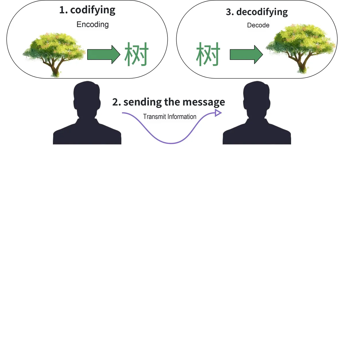
- Purpose: to "transport" information from the sender to the receiver.
- Basic model: transmitter → channel → receiver (for example, when people talk to each other, the "speaker" is the transmitter, the "air" is the channel, and the "listener" is the receiver).
- Key Metrics: Effectiveness (whether information transmission is efficient), Reliability (whether information transmission is accurate), Communication Rate (the speed of information transmission), Transmission Distance, Propagation Speed.
0.2 Basic Classification of Common Communication Protocols
The Communication Protocol we commonly refer to is a set of rules that standardize "how information is transmitted", and it can be categorized into the following types based on whether the transmission medium is "wired" or "wireless":
- Wired Communication Protocol (transmits information via physical cables such as network cables, serial cables, buses, etc.):
- Ethernet (ETH, Ethernet):
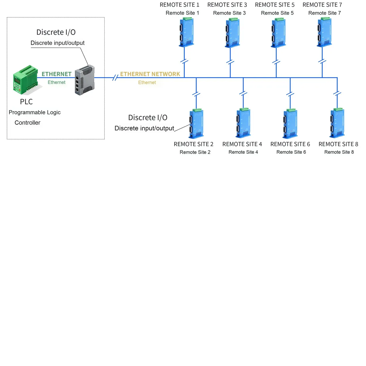
- Status: In existing local area networks, it is the most widely used Communication Protocol standard.
- Application: LAN data transmission for enterprises and households (e. g., a computer connecting to a router via an Ethernet cable to access the Internet).
- CAN communication (Controller Area Network): a multi-master wired serial communication bus that transmits data via wired media such as twisted pairs; it supports "error detection + error notification + error recovery" and can achieve stable transmission in complex electromagnetic environments.
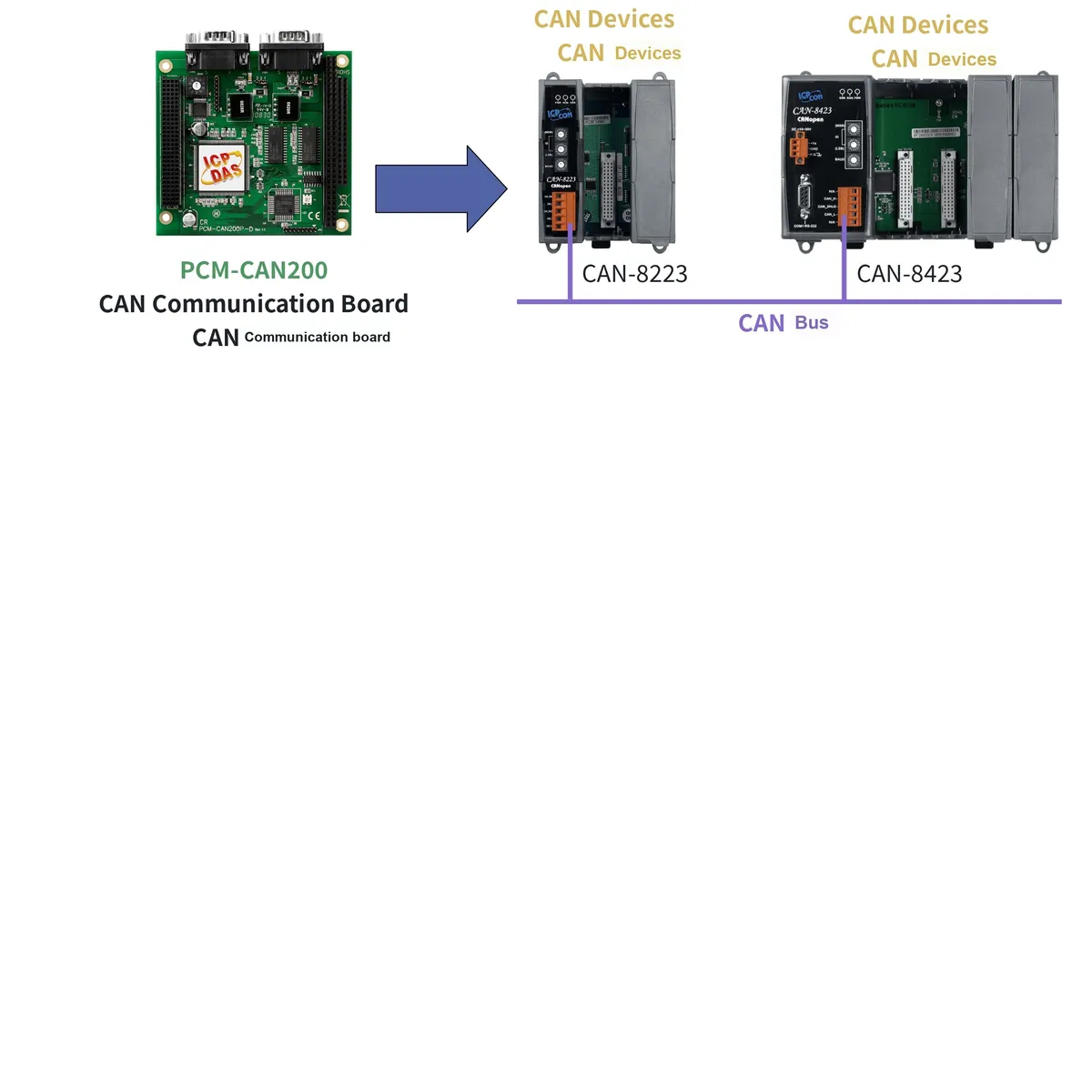
- Applications: Automotive electronics (signal interaction between in-vehicle devices, such as communication of engines and brake systems), industrial automation (interlocked control of equipment), medical devices and other scenarios.
- M-BUS (Meter Bus)
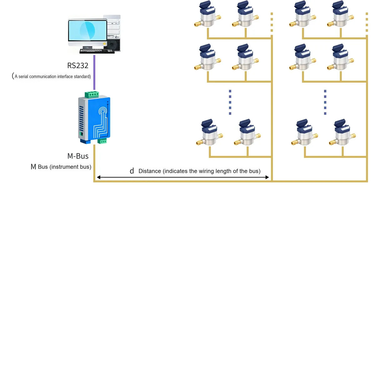
- Features: With two non-polarized transmission lines, it simultaneously realizes "power supply for devices + serial data transmission"; multiple slave stations (such as electricity meters and water meters) can be connected in parallel to the bus via "different IDs".
- Application: Specially designed for consumption measuring instruments (such as electricity meters and gas meters) and counters to transmit metering information.
- USB (Universal Serial Bus)
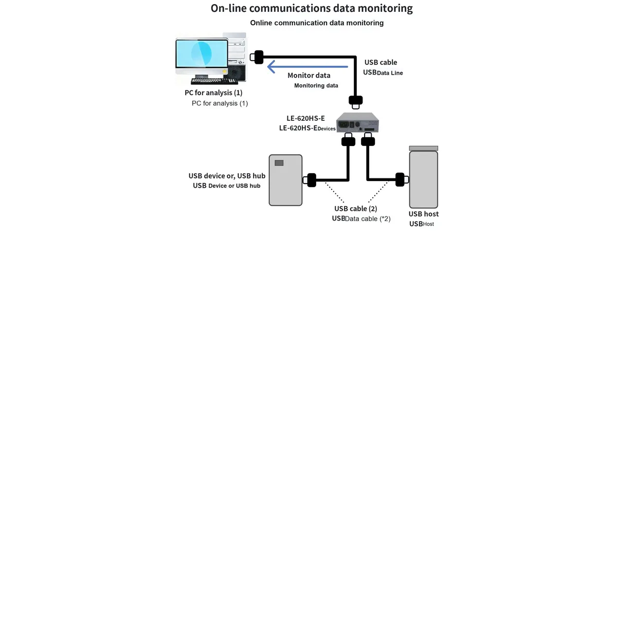
- Features: It belongs to " high-speed serial bus ", which can not only transmit data but also supply power to lower-level devices; it features easy installation, simple expansion ports, diverse transmission modes and excellent compatibility.
- Development: It has evolved from the initial Version 1.0 (with a transmission rate of 1.5Mbps) to the current Version 4.0 (with a transmission rate of up to 40Gbps), which can meet demands such as fast charging for mobile phones and high-speed transmission of external hard drives.
- Serial port protocols (including RS232, RS422, RS485) A serial port is a general term for "serial data interfaces", whose core function is to transmit bytes in units of "bits", and different sub-protocols have distinct characteristics:
- RS232: It features a maximum transmission rate of 20kbps and a transmission distance of only 15 meters, and commonly uses "9-pin (Db-9)" or "25-pin (Db-25)" interfaces, such as the serial ports on early computers.
- RS422: adopts balanced communication + twisted pair for transmission, with the rate increased to 10Mb/s and the transmission distance extended up to 1200 meters (supporting "full-duplex", namely simultaneous two-way transmission).
- RS485: adopts half-duplex transmission (only one-way transmission is allowed at the same time), with a transmission rate of 10Mb/s and a transmission distance up to 1200 meters, which is suitable for multi-device networking, such as sensor clusters in industrial sites.
- Low-speed board-level / inter-board serial protocols are mostly used for short-distance communication between chips and circuit boards, and the common ones are as follows:
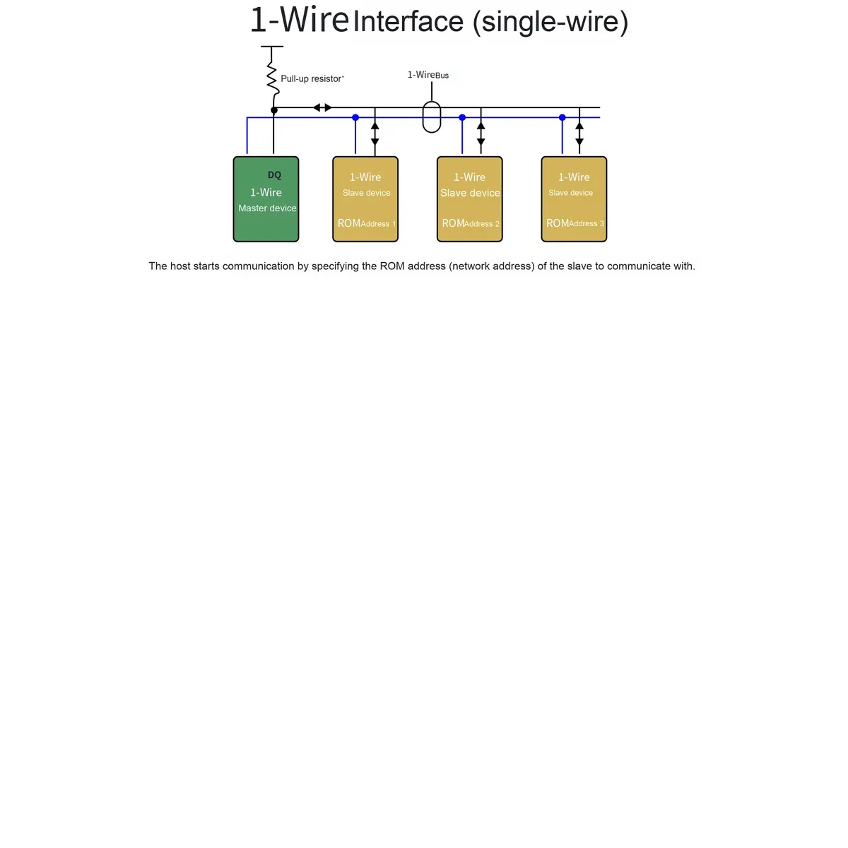
- 1-Wire protocol: only requiring one single bus to realize the functions of "clock + data + control", which belongs to half-duplex communication; it features simple wiring, low hardware overhead, low cost, and facilitates bus expansion (e. g., multiple sensors share one bus to form a network).
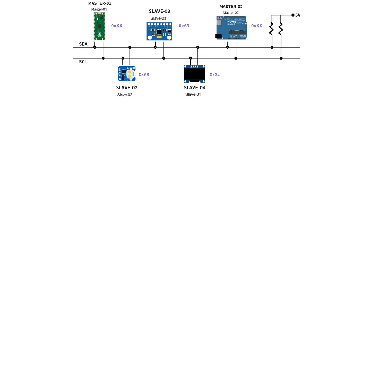
- I2C communication (Inter-Integrated Circuit): only requires 2 wires (SDA: Serial Data Line; SCL: Serial Clock Line), both of which are "bidirectional I/O lines"; it supports "multi-master + multi-slave" architecture (with only 1 master active at the same time), and features transmission rates of "up to 400Kbit/s in fast mode and 3.4Mbit/s in high-speed mode"(e. g., communication between microcontrollers and sensors or memory chips).
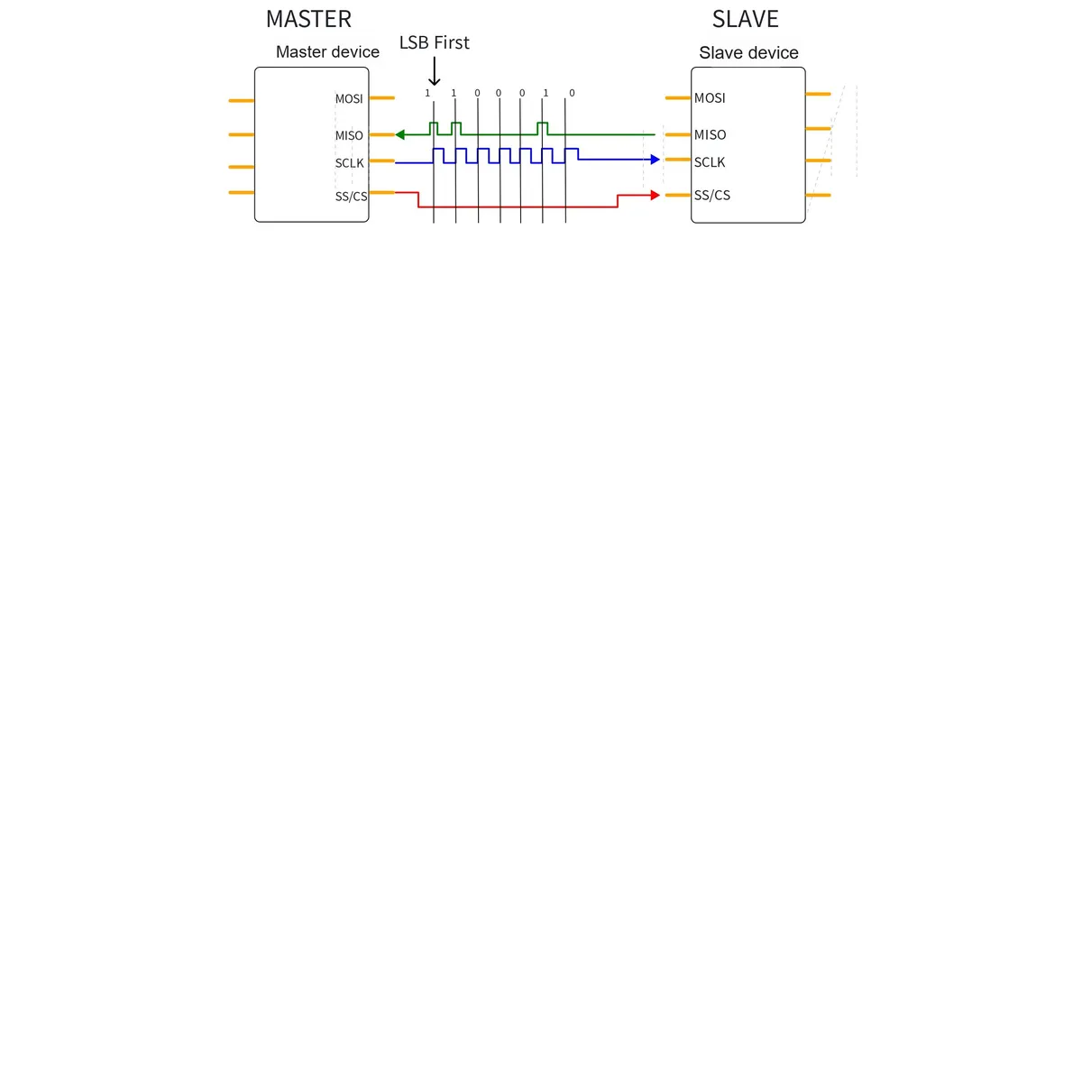
- SPI communication (Serial Peripheral Interface): a full-duplex synchronous serial bus developed by Motorola, which requires 4 wires (CS: Chip Select; SCLK: Serial Clock; MOSI: Master Out, Slave In; MISO: Master In, Slave Out); it is mainly used for high-speed communication between MCUs (Microcontroller Control Units) and peripheral devices (such as EEPROM, Flash, ADC (Analog-to-Digital Converter), DSP (Digital Signal Processor), etc.).
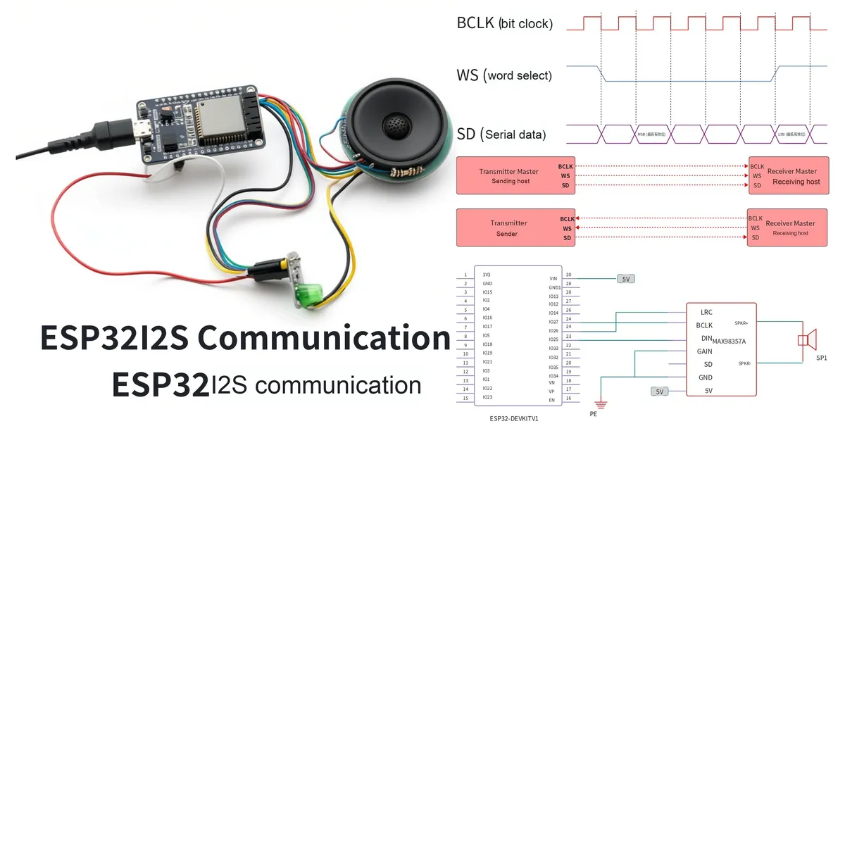
- I2S communication (Inter-IC Sound): a bus standard developed by Philips for digital audio transmission. It transmits data signals and clock signals separately to avoid audio distortion caused by time difference, and is widely used in embedded audio systems such as audio equipment and voice modules.
- Ethernet (ETH, Ethernet):
- Wireless Communication Protocol (transmits information via electromagnetic waves (radio, infrared, etc.) without the need for physical cables):
- Infrared Data Association (IrDA)
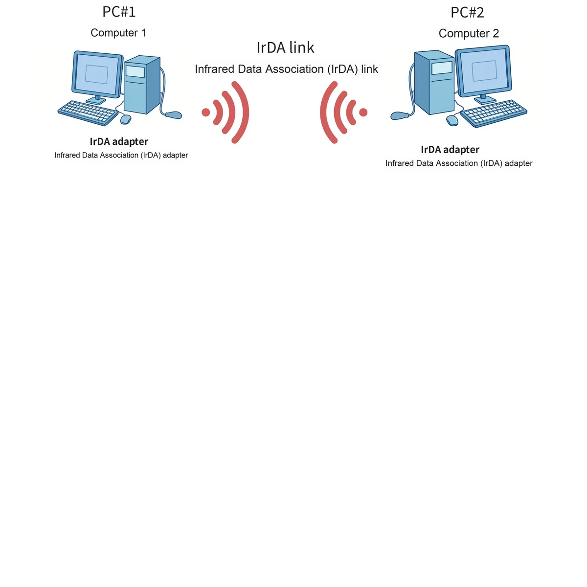
- Principle: Use infrared rays to transmit information.
- Features: large transmission capacity, strong confidentiality, excellent anti-electromagnetic interference capability; simple equipment structure and small size.
- Applications: indoor short-range communication (e. g., TV remote controls), short-distance remote control, etc. ; compliant with standards such as IrDA 1.0 and IrDA 1.1/FIR.
- WiFi
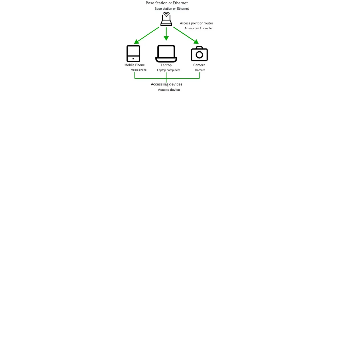
- Principle: Via the 2.4GHz UHF band or the 5GHz SHF ISM radio band, communication between devices is realized.
- Features: A "local wireless network" based on the IEEE 802.11 standard, commonly used for devices such as computers, tablets and mobile phones to connect to routers for internet access.
- Bluetooth / BLE (Bluetooth Low Energy)
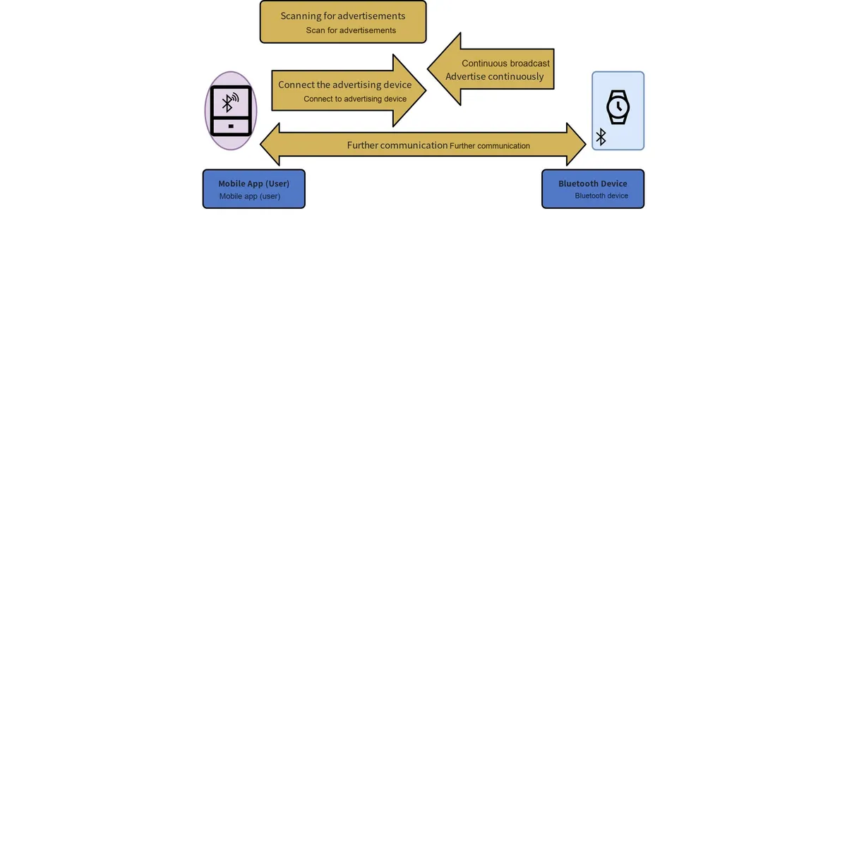
- Principle: Data is transmitted via UHF radio waves in the 2.4–2.485GHz ISM band.
- Features: Suitable for short-distance data transmission; among them, BLE (Bluetooth Low Energy) focuses on "low power consumption", which can extend the battery life of devices (such as wearable devices like smart watches and Bluetooth bracelets).
- Application: Enables short-range data exchange between fixed devices, mobile devices, and building personal area networks (e. g., the connection between Bluetooth earbuds and mobile phones).
- Zigbee
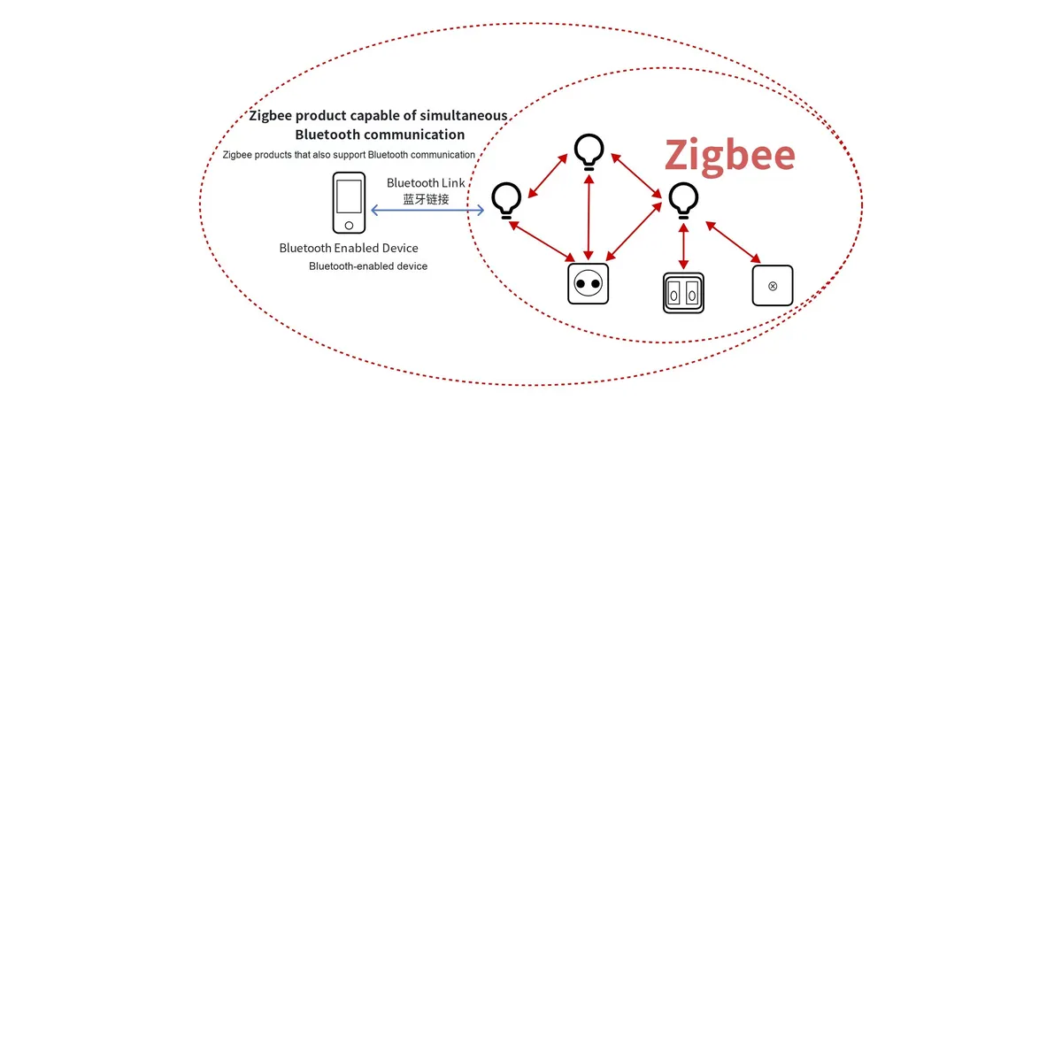
- Features: It is an "open global standard" designed specifically for M2M (Machine-to-Machine) networks; it features "low cost, low power consumption, low latency, and low duty cycle"(which can maximize the battery life of devices).
- Application: Smart home sector (e. g., networking of smart lights, temperature and humidity sensors to enable inter-device linkage).
- NB-IoT (Narrowband Internet of Things)
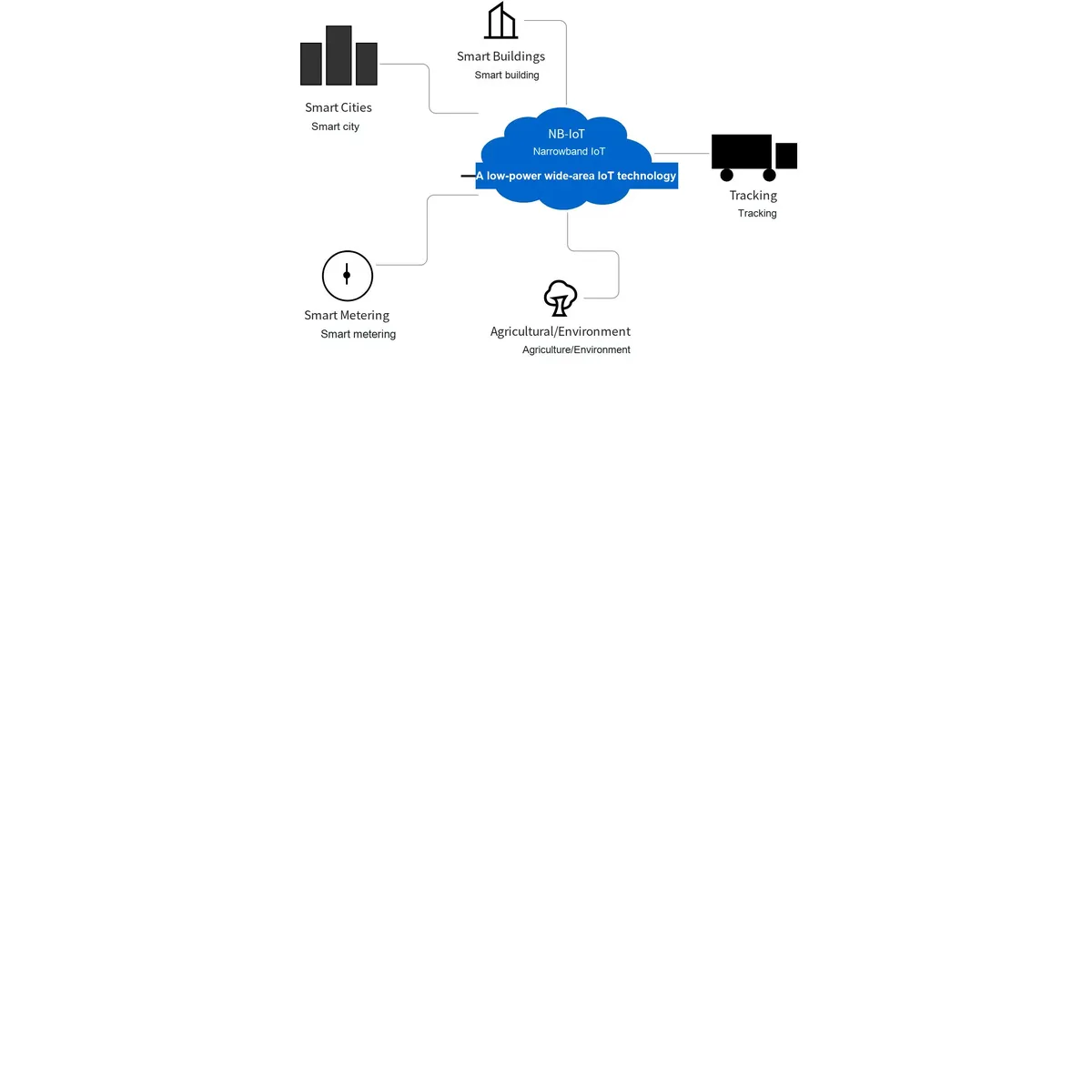
- Principle: Built on cellular networks, it only consumes a bandwidth of approximately 180 KHz and can be directly deployed on GSM networks, UMTS networks or LTE networks.
- Features: It can reduce deployment costs, achieve seamless upgrades, and support cellular data connectivity for low-power devices over a wide area network (cross-region).
- Applications: Wide-area IoT scenarios such as smart cities (e. g., remote meter reading) and logistics tracking.
- LoRa (Long Range)
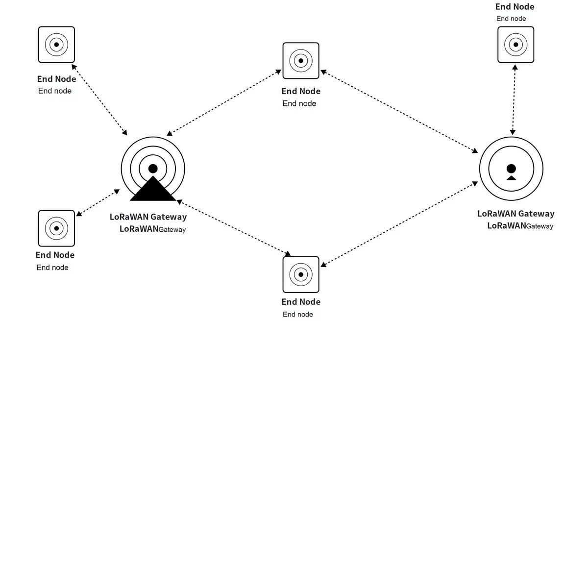
- Features: It belongs to LPWAN (Low-Power Wide-Area Network) technology, and is the "ultra-long-distance wireless transmission solution based on spread spectrum technology" promoted by Semtech, a US company; it features the characteristics of "long distance, low power consumption (long battery life), multiple nodes and low cost".
- Application: Sensor networking in remote areas (e. g. farmland environmental monitoring, remote monitoring of oilfield equipment).
- Infrared Data Association (IrDA)
0.3 Classification and Concepts of Communication Methods
0.3.1 Classification by "Data Transmission Mode": Serial Communication vs. Parallel Communication
The data transmission mode determines "how multiple data bits are transmitted simultaneously or in a time-division manner", and the two have significantly different characteristics: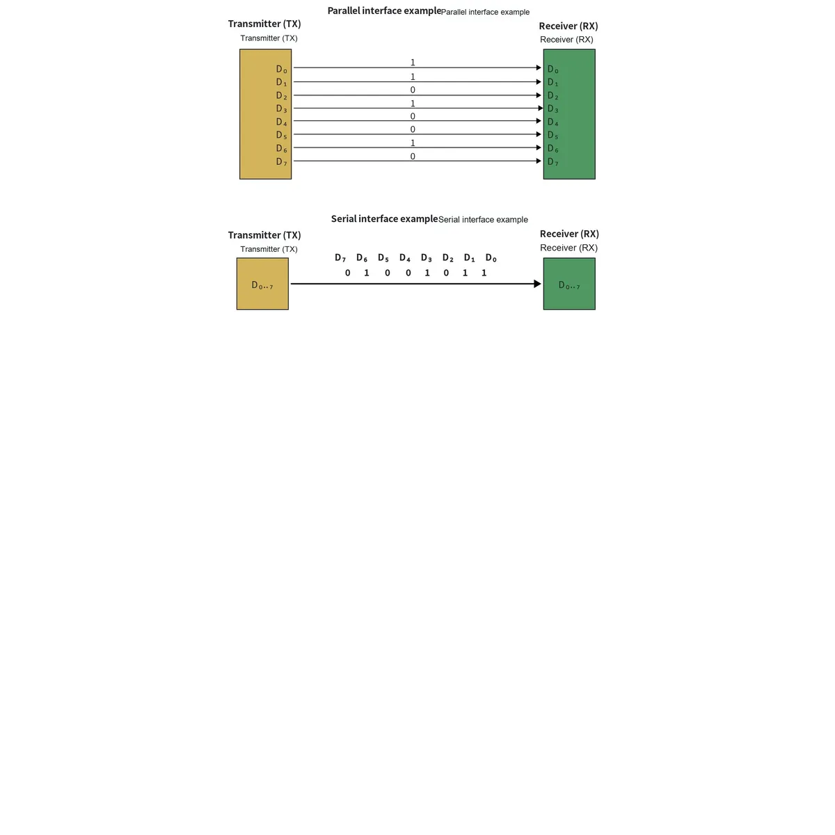
- Serial communication: A communication mode between devices that uses a small number of data signal lines (generally fewer than 8) to transmit data bit by bit in the form of data bits, which is analogous to a single-lane highway where only one data bit can be transmitted at a time.
- Parallel communication: uses 8,16,32,64 or even more data lines to transmit multiple data bits simultaneously (analogous to a "multi-lane highway that can carry multiple data bits at the same time").
Features | Serial Communication | parallel communication |
Communication Distance | relatively far | relatively close |
anti-interference capability | relatively strong | weak |
transmission rate | relatively slow | relatively high |
Cost | Lower (saves wiring materials and PCB layout area, especially for long-distance scenarios) | Higher (requires more data cables) |
Since parallel transmission imposes extremely high requirements on the "synchronization of multiple data lines", and as communication rates increase, signal interference will significantly degrade performance. Therefore, high-speed scenarios increasingly adopt "high-speed serial differential transmission"(which uses a serial approach to achieve high bandwidth comparable to that of parallel transmission).
0.3.2 Classification by "Data Synchronization Mode": Synchronous Communication vs Asynchronous Communication
The synchronization method determines "how the transmitting and receiving parties maintain consistent data timing", and the core difference lies in whether it relies on "clock signals" for synchronization: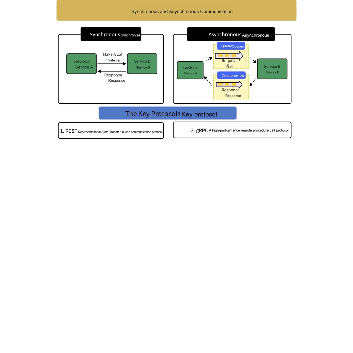
- Synchronous communication: The transmitting and receiving parties use a single clock signal line as a synchronization reference, and coordinate the synchronous data transmission driven by the "rising edge / falling edge" of the clock signal (among the data signals, "the vast majority are valid data").
- Asynchronous communication: Instead of using a separate clock signal, it inserts synchronization flag bits into the data signal (such as "start bit, parity bit, stop bit"), or transmits data in the form of "packeted frames"; in some scenarios, both parties need to agree on a "transmission rate" to assist synchronization.
Dimension | Synchronous Communication | asynchronous communication |
Clock Dependency | Relies on a separate clock signal line | It does not rely on an independent clock, and achieves synchronization by means of the identifier bits or frame structure within the data. |
Proportion of valid data | High (almost all data signals are valid content) | Low (the data includes additional identifiers such as start bit, parity bit, stop bit, etc.) |
Clock Error Tolerance | Low (the two parties' clocks must be strictly synchronized; any slight deviation beyond the allowable margin will result in data loss) | High (strict clock synchronization is not required, and fault tolerance is achieved via flag bits) |
efficiency | High (high proportion of valid data) | Low (additional flag bits occupy transmission resources) |
0.3.3 Classification by "Relationship Between Transmission Direction and Time": Simplex, Half-duplex, and Full-duplex Communication
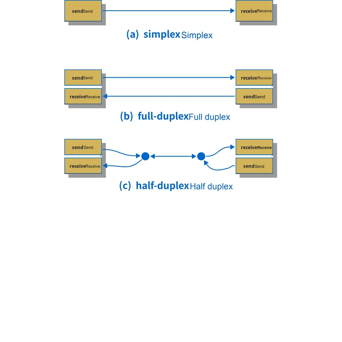
This dimension focuses on "the transmission direction of data in the channel (simplex / duplex)" and "whether simultaneous transmission and reception are possible in terms of time".
Communication Method | Specific Instructions |
full-duplex | At the same time, both the transmitting and receiving parties can send and receive data simultaneously (for example, during a mobile phone call: you can hear the other party while speaking, and you can respond when the other party is speaking) |
half-duplex | Both the transmitting and receiving parties can perform two-way transmission, but at a given time, they can only either "transmit" or "receive"(for example, a walkie-talkie: you have to press the talk button to transmit, and release it to receive audio) |
Simplex | Data can only ever be transmitted from a "fixed sender" to a "fixed receiver", and transmission in the reverse direction is impossible (e. g., television broadcasting: TV stations transmit signals, and televisions can only receive them). |
0.3.4 Core Concepts of Communication Rate: Bit Rate, Baud Rate, Symbol
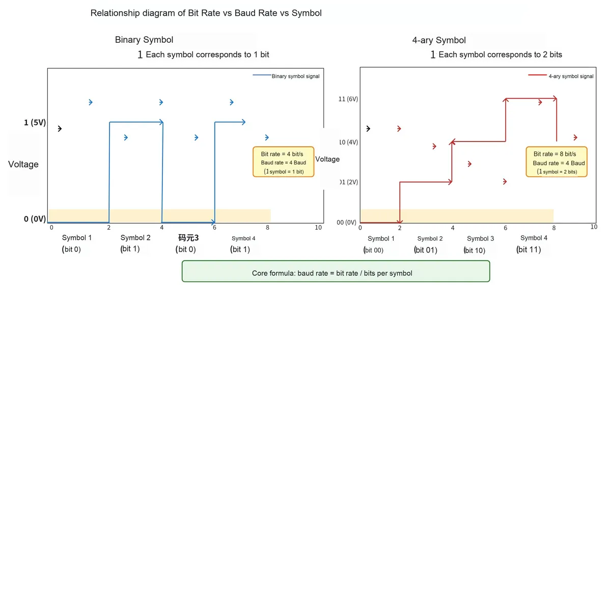
"Rate" measures the "transmission efficiency" of communication, and it is necessary to clarify the differences and connections between three key terms:
- Bit rate: the number of binary bits transmitted per second, with the unit being "bits per second (bit/s)".
- Baud rate: the number of symbols transmitted per second ("symbol" refers to the basic signal unit that carries information in digital communications).
- Symbol: A symbol that represents binary digits using "signals with identical time intervals", and the "signal within that time interval" is the symbol. If the number of discrete states of a symbol is greater than 2 (e. g., M-ary), it is an M-ary symbol.
- Binary symbol: If "0V represents 0 and 5V represents 1", one symbol can only represent two states, "0 or 1"(corresponding to 1 binary bit). In this case, baud rate = bit rate (because one symbol carries one bit).
- Multi-level symbol: If "0V represents 00,2V represents 01,4V represents 10, and 6V represents 11", one symbol can represent four states: "00,01,10,11"(corresponding to 2 binary bits). In this case, baud rate = bit rate ÷ 2 (since one symbol carries 2 bits).
- The Relationship Between Baud Rate and Bit Rate: Baud Rate = Bit Rate / Number of Bits Per Symbol.
0.4 Definitions and Relationships of Interfaces, Buses and Protocols
The core of a communication system lies in the combination of " hardware connection " and " software rules ". Communication interface (hardware connection standard), communication bus (interconnection path for multiple components), and Communication Protocol (data transmission rule) are the three key elements, whose definitions and relationships are as follows:
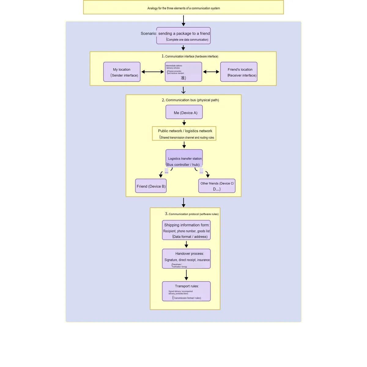
Communication interface: refers to the hardware connection standard for input/output, and the "hardware interface that implements communication functions" is exactly a communication interface. According to the "data transmission mode", communication is divided into serial communication (transmitted bit by bit in sequence) and parallel communication (multiple bits transmitted simultaneously), so communication interfaces also fall into two corresponding categories:
- Serial Interface (Serial Port): A hardware interface that supports serial communication (such as the
RS-232DB9interface). - Parallel Interface (Parallel Port): A hardware interface that supports parallel communication (e. g., the parallel port on early printers).
Communication bus: It is a set of transmission channels, consisting of "data lines, address lines, control lines" and the like, serving as the "path" for data transmission between logic devices (such as chips and modules). In a broad sense, computer communication is divided into serial and parallel communication according to "transmission characteristics", and the corresponding buses are also divided into:
- Serial buses: such as I2C, SPI, UART (serial port bus), etc. , which transmit data bit by bit.
- Parallel Bus: For example, the early PCI bus transmits multiple bits of data simultaneously.
In addition, buses can also be classified from other dimensions (more detailed scenario division):
Classification Dimension | Subcategory | Description |
Functional Division | Internal Bus, System Bus, I/O Bus | Internal bus: interconnects modules inside a chip; System bus: connects CPU, memory and peripherals; I/O bus: enables interaction between peripherals and the system |
timing control mode | Synchronous Bus, Asynchronous Bus | Synchronous bus: Data synchronization is achieved by a unified clock signal; Asynchronous bus: Synchronization is realized by handshake signals (non-clock signals) |
Data Transmission Format | Serial Bus, Parallel Bus | Consistent with the logic of "communication interface", data is transmitted bit by bit or multiple bits simultaneously respectively. |
Communication Protocol is a set of rules for data transmission, serving as an "overall collaboration framework" — it defines the interaction relationships among interface devices, components, electrical signals, buses and transmission channels to ensure that all components can cooperate to complete "signal transmission and data interaction".
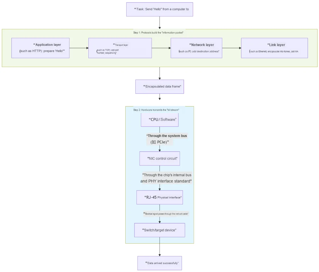
The relationship among the three is summarized as follows:
- Interface: emphasizes " hardware connection between two components ", focusing on "conversion of signal form and data format"(e. g., "how to physically connect two devices").
- Bus: It places more emphasis on " interconnection and expansion of multiple components ", highlighting "scalability, flexibility and industry standardization"(many buses follow unified standards, such as USB and PCIe).
- Protocol: it is " software rules running on top of hardware (interfaces, buses)", which specifies "how to use interfaces and how buses transmit data".
It should be noted that interfaces and buses are sometimes not strictly distinguished (often collectively referred to as "bus interface" or "interface bus"); a communication bus must match a Communication Protocol to enable communication (for example, the USB bus needs to comply with the USB protocol).
1. Hardware Explanation
1.1 Serial Communication
1.1.1 Basic Concepts of Serial Communication
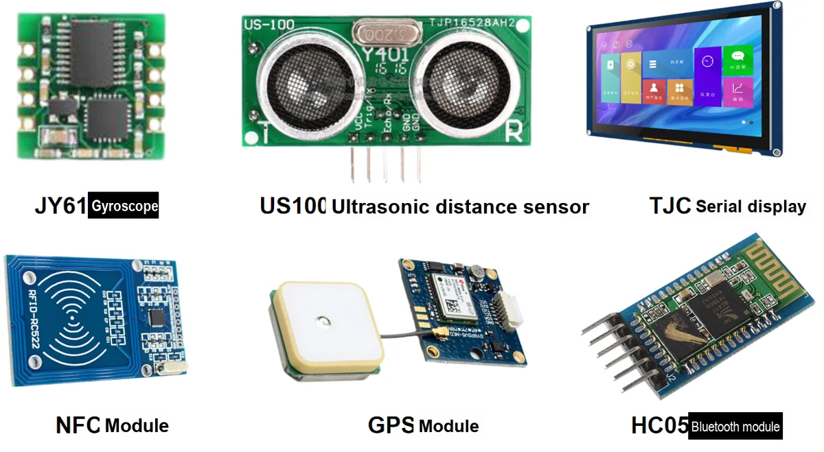
UART stands for Universal Asynchronous Receiver/Transmitter, which we usually refer to as serial communication. It is one of the most commonly used communication methods between devices. Despite its low communication rate, most electronic devices support data transmission, communication, control, simulation and debugging via this communication method due to its simple wiring and easy-to-understand protocol.Many devices or modules even provide dedicated serial ports for communication and control, such as GPRS modules, Bluetooth/WiFi transparent transmission modules, gyroscopes, LCD screens, etc.
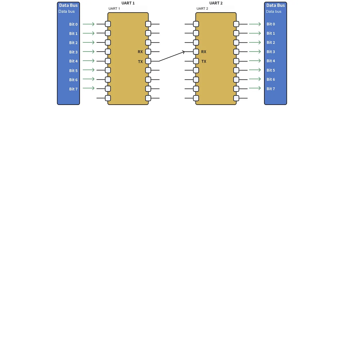
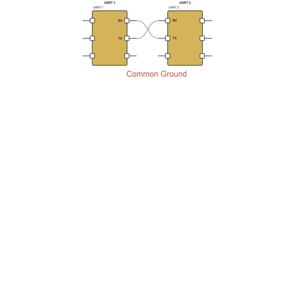
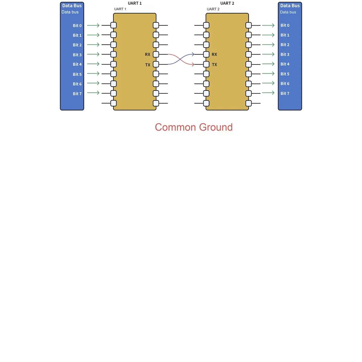
UART enables full-duplex communication using only one data receive line and one data transmit line, and adopts TTL/CMOS levels. Typical serial communication is implemented with three lines, namely: transmit line (TX), receive line (RX) and ground line (GND). During communication, the TX and RX of the two parties must be cross-connected and the GNDs must be connected to enable normal communication, as shown in the following figure:
In the internal structure of the UART peripheral of a microcontroller, the data bus is connected in parallel to the generator/receiver of the serial port; data is transmitted from the transmitter to the receiver in a serial manner, and the receiver converts the serial data into parallel data for use by the receiving device.
Serial Communication and Parallel Communication
According to the data transmission mode, communication can be divided into serial communication and parallel communication. Serial communication refers to a communication mode in which data is transmitted bit by bit between devices through a small number of data signal lines (generally less than 8), ground lines and control signal lines. Parallel communication generally refers to a communication mode that uses 8,16,32,64 or more data lines for transmission.
Simply put, parallel communication is like a multi-lane highway that can transmit multiple bits of data simultaneously, while serial communication is like a single-lane highway that can only transmit one bit of data at a time.
Since multiple data bits can be transmitted at one time, parallel communication can transmit a much larger amount of data when the data transmission rate is the same, while serial communication can save the hardware cost of data lines (especially for long-distance transmission) and the wiring area of PCB. Meanwhile, compared with parallel communication, serial communication features stronger anti-interference capability, longer communication distance, and lower requirements for clock synchronization.
UART does not require an external clock line, but the two communicating parties must agree on parameters such as the start bit, body data, parity bit and stop bit to communicate properly, making it an asynchronous communication method.
Asynchronous Communication and Synchronous Communication Modes
According to the data synchronization mode of communication, it can be divided into two types: synchronous communication and asynchronous communication, which can be simply distinguished by whether a clock signal is used during the communication process:
- In synchronous communication, both the transmitting and receiving devices use a single signal line to represent the clock signal. Driven by the clock signal, the two parties coordinate and synchronize data. During communication, it is usually agreed by both parties that the data line is sampled at the rising edge or falling edge of the clock signal.
- In asynchronous communication, clock signals are not used for data synchronization; instead, synchronization signal bits are directly interspersed in the data signals, or the main data is encapsulated and transmitted in the format of data frames. For UART serial communication and most serial communication methods, the two parties also need to agree on the data transmission rate to achieve better synchronization.
In synchronous communication, the vast majority of the content transmitted by data signals is valid data, while asynchronous communication includes various identifiers of frames, so synchronous communication boasts higher efficiency, yet the allowable clock error between the two parties in synchronous communication is relatively small, whereas the allowable clock error between the two parties in asynchronous communication is relatively large.
1.1.2 Serial Port Data Packet Format
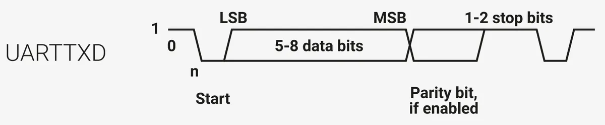
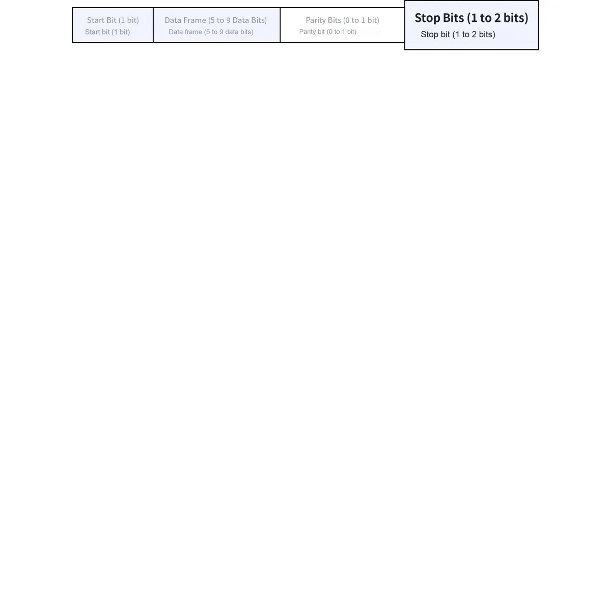
In UART, data is transmitted in the form of data packets. A data packet consists of a start bit, valid data bits, a parity bit, and a stop bit. The two communicating parties must agree on the same data packet format to transmit and receive data normally, and its composition is shown in the following figure:
MSB and LSB, Big-Endian and Little-Endian
MSB (Most Significant Bit): the most significant bit, which refers to the bit position representing the highest value in a binary number and has the greatest impact on the corresponding numerical value.
LSB (Least Significant Bit): Least Significant Bit, which refers to the bit that represents the lowest value in a binary number
For example, in the binary number 1001 (which equals 9 in decimal), the leftmost "1" is the MSB, which has the greatest impact on the value, corresponding to a variation range from 1 to 9, while the rightmost "1" is the LSB, as it only causes the value to change from 8 to 9.
Big-Endian: In this mode, the higher-order bytes of data are stored at the lower memory addresses, while the lower-order bytes are stored at the higher memory addresses.
Little-Endian: the lower-order byte of data is stored at the lower memory address, while the higher-order byte is stored at the higher memory address.
As can be seen, during the serial port transmission and reception process of the Raspberry Pi Pico, the lower-bit data is transmitted first and the higher-bit data is transmitted later, which is in little-endian mode. Many ARM and DSP devices adopt the little-endian mode, and some ARM processors can also select between big-endian mode and little-endian mode via hardware.
The meaning of each bit and the optional parameters are as follows:
- Start bits / Stop bits:
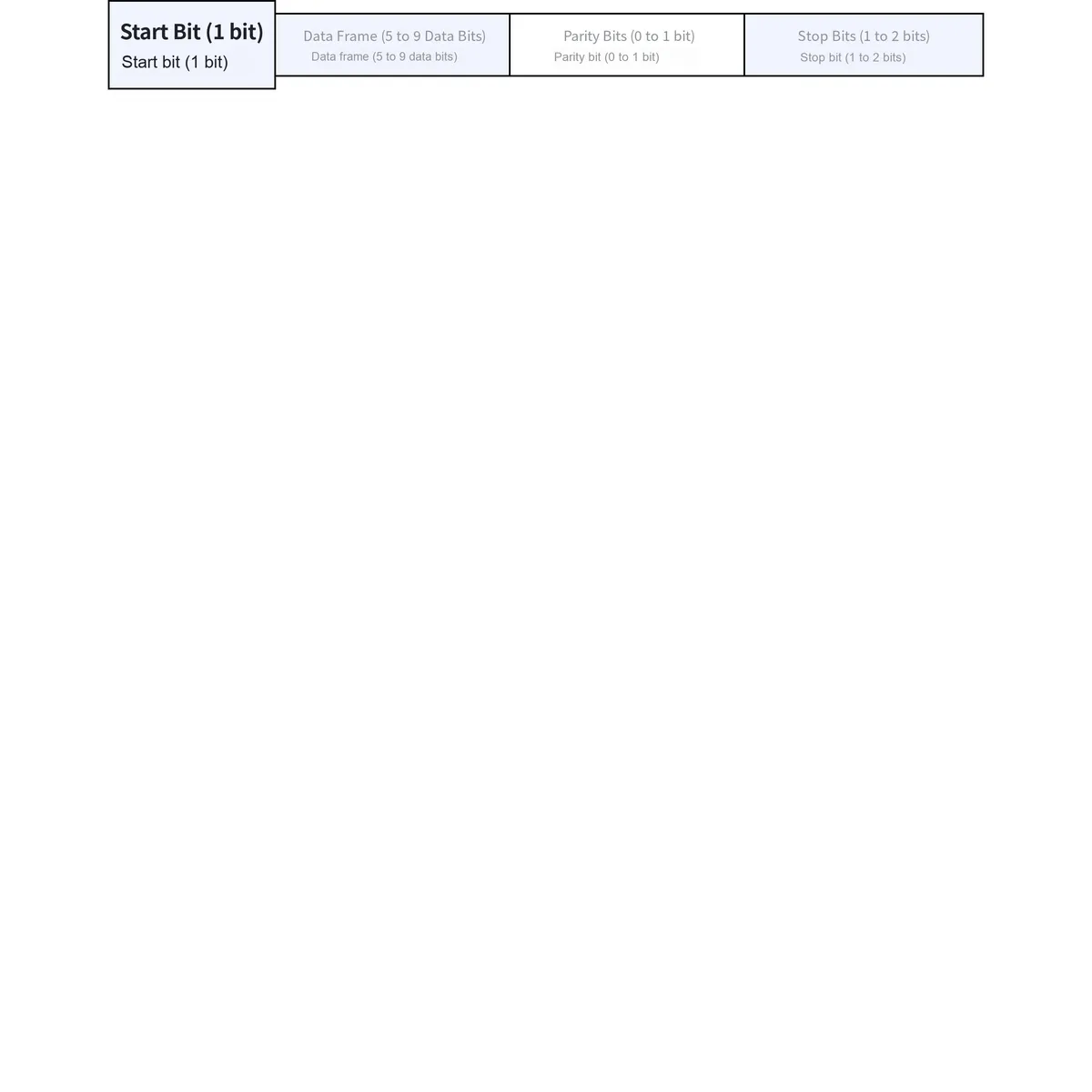
A data packet in serial communication starts with a start signal and ends with a stop signal. The start signal of the data packet is represented by one data bit of logic 0, while the stop signal of the data packet can be represented by 1 or 2 data bits of logic 1.
- Data bits:
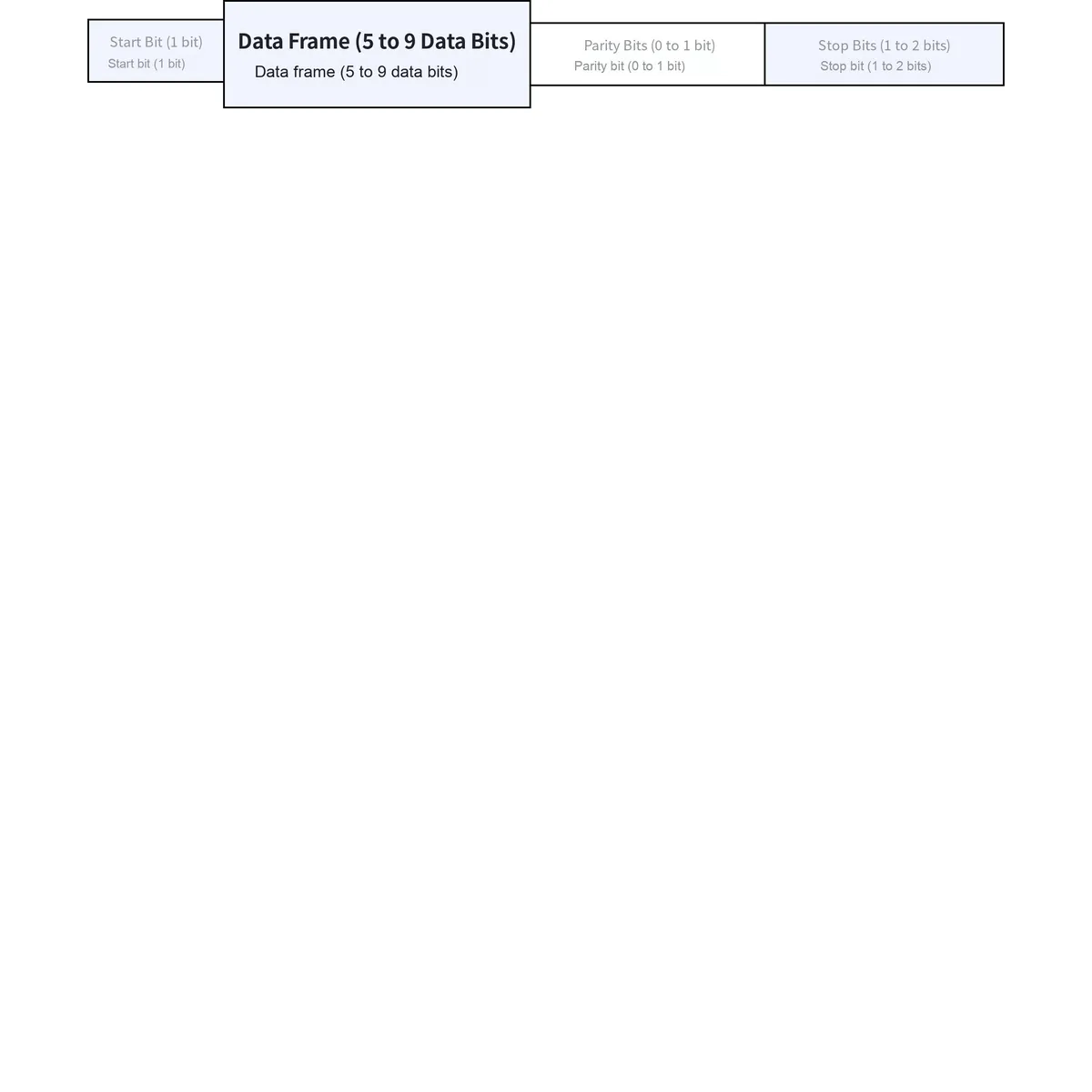
Immediately following the start bit of the data packet is the main data content to be transmitted, also referred to as payload data, and the length of the payload data is usually specified as 5,6, 7 or 8 bits.
- Parity bits:
Following the valid data bits, there is an optional parity bit. Since data communication is relatively vulnerable to external interference that causes deviations in transmitted data, this issue can be addressed by adding a parity bit during transmission. Common parity checking methods include odd parity, even parity, space parity, mark parity, and no parity.
Verification Method
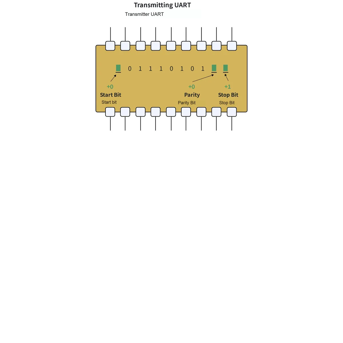
- Odd Parity: Odd parity requires that the total number of "1" s in both the valid data and the parity bit is an odd number. For example, for an 8-bit valid data 01101001, there are 4 "1" s in total; to achieve the odd parity effect, the parity bit is set to "1", so the final transmitted data consists of the 8-bit valid data plus the 1-bit parity bit, totaling 9 bits.
- Even Parity: Even parity is the exact opposite of odd parity in terms of requirements: it requires the total number of "1" s in both the frame data and the parity bit to be an even number. For example, for the data frame 11001010, the number of "1" s in this data frame is 4, so the even parity bit is "0".
- 0 Check: In 0 check, regardless of the content in the valid data, the check bit is always "0"
- 1 Check: 1 Check means the check bit is always "1"
For normal serial communication between two devices, in addition to setting the same parameters for each bit, it is also necessary to correctly configure the baud rate of both devices, which refers to the length of each symbol for signal decoding; common baud rates include 4800,9600,115200, etc.
Common Concepts of Communication Rate: Symbol, Bit Rate and Baud Rate
The so-called symbol is defined as follows:
In digital communication, symbols with identical time intervals are often used to represent one binary digit. A signal within such a time interval is referred to as a (binary) symbol. This interval is called the symbol length. It is worth noting that when the number of discrete states of a symbol is greater than 2 (e. g., M is greater than 2), the symbol is an M-ary symbol. For instance, in common communication transmission, 0V is used to represent the digit 0 and 5V to represent the digit 1. In this case, one symbol can represent two states, 0 and 1, so one symbol equals one binary bit, and the baud rate is consistent with the bit rate at this point;In communication transmission, if 0V, 2V, 4V and 6V are used to represent the binary numbers 00,01,10 and 11 respectively, then each symbol can represent four states, namely two binary bits. Therefore, the number of symbols is half of the number of binary bits, and the baud rate at this time is half of the bit rate.
Bit rate refers to the number of binary bits transmitted per second, and its unit is bits per second (bit/s).
Baud rate refers to the number of symbols transmitted per second.
The relationship between the two is as follows: Baud rate = Bit rate / Number of bits per symbol (In the binary case, baud rate equals bit rate)
For example, the common baud rate selected for single-chip microcomputer serial communication is 9600 bps, which means that 9600 bits are transmitted per second. When observing the waveform on the serial line at a time scale of 1 second, it can be regarded as a high-low level signal with continuous time and discrete amplitude, which is divided into 9600 equal parts.
1.1.3 Serial Port Data Transmission Process
Below, we will take the transmission and reception process of a data packet in the serial port as an example to explain the correct process of serial port data transmission:
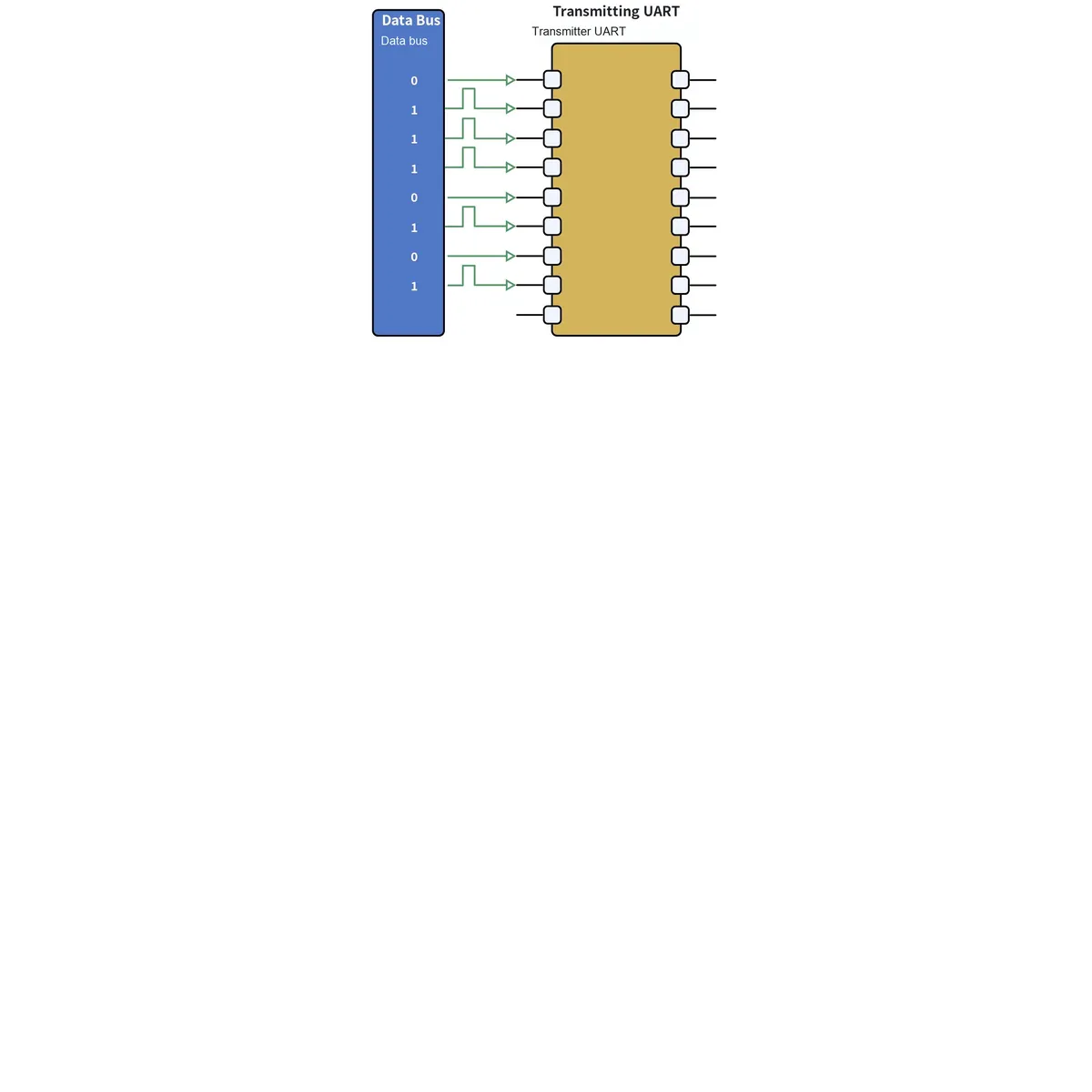
- First, the data bus of the transmitting device transmits data to the serial transmitter in a parallel manner:
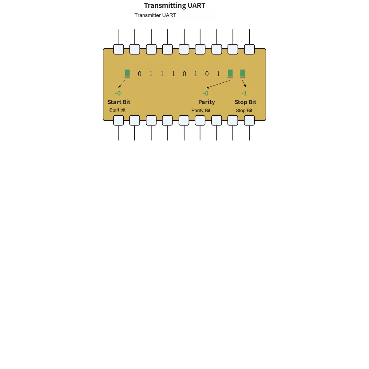
- The serial transmitter adds a start bit, a parity bit and a stop bit to the data frame:
- A serial port transmitter sends a data packet to the serial port receiver of another device, and the serial port receiver samples the data line at a preconfigured baud rate:
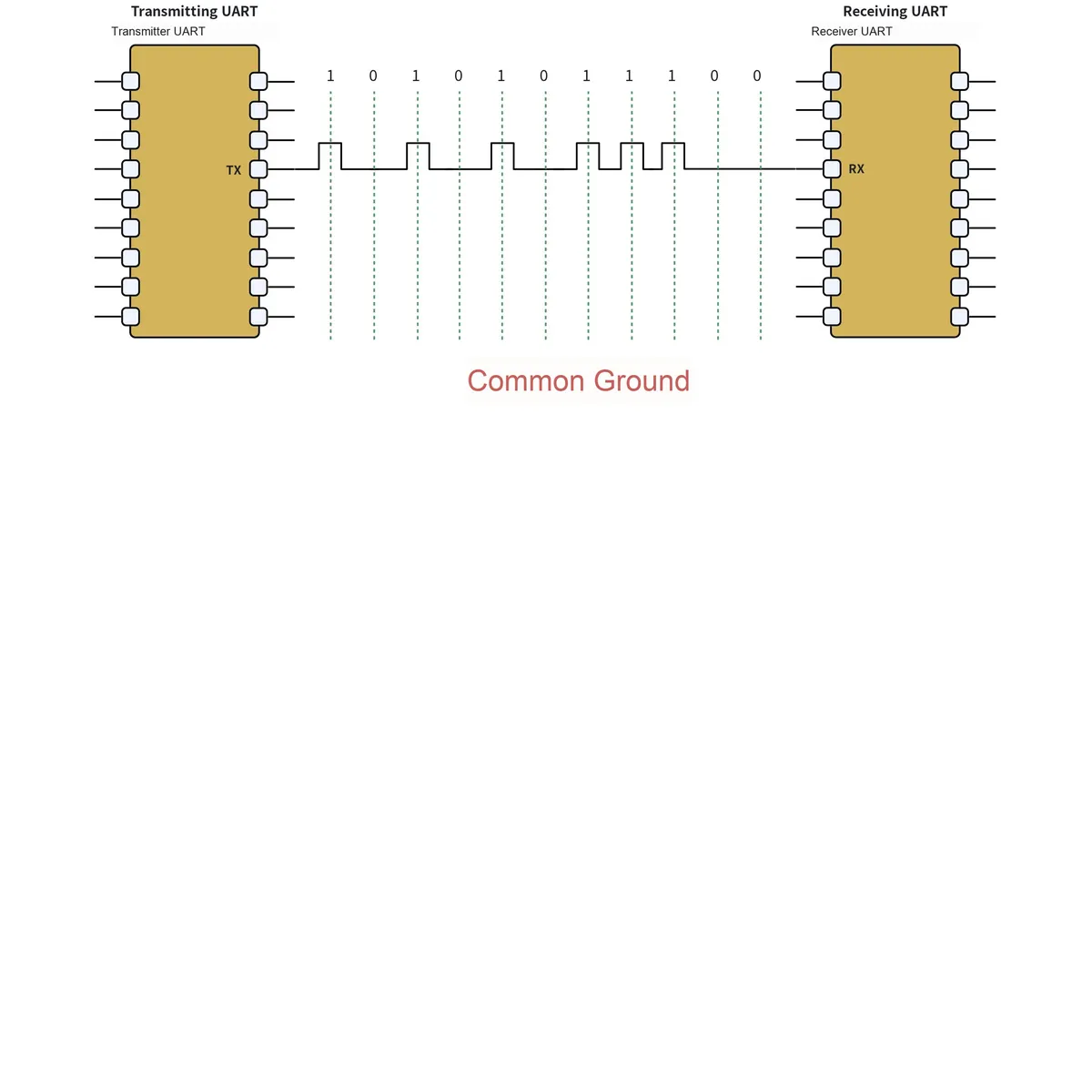
The overall process is as follows:
- When not transmitting data, the serial transmission data line usually remains at a high level. To initiate data transmission, the serial transmitter pulls the transmission line from the high level to a low level for one clock cycle. When the serial receiver of the receiving device detects the transition from high voltage to low voltage, it starts sampling at the set baud rate frequency and reads the bits in the data frame:
- A data frame contains the actual data being transmitted, and its length can range from 5 to 8 bits if a parity bit is used; if no parity bit is used, the data frame can be 9 bits long. In most cases, data is transmitted starting with the least significant bit:
- After the serial port receiver of the receiving device reads the data frame, it counts the number of high-level values in the data frame and checks whether the total number is even or odd. If the parity bit is set to even parity, the total number of high levels in the data frame shall be an even number; if the parity bit is set to odd parity, the total number of high levels in the data frame shall be an odd number.
When the parity bit matches the data, the serial port receiver determines that the received data is correct; otherwise, the received data is erroneous (caused by factors such as circuit noise or transmission interruption).
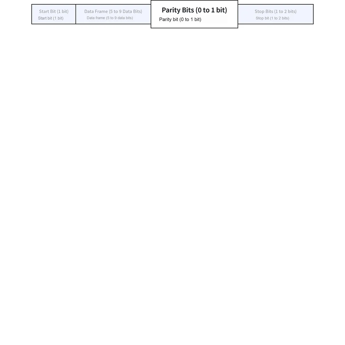
- To send a signal indicating the end of packet transmission, the serial transmitter pulls the data transmission line from a low level to a high level, holding this state for 1 to 2 clock cycles:
- After the serial port receiver receives the entire data packet, it discards the start bit, parity bit and stop bit therein:
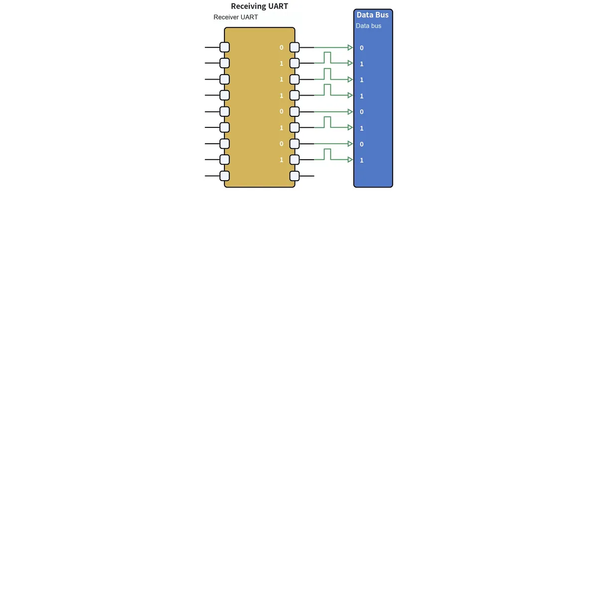
- The serial port receiver converts serial data back into parallel data and transmits it to the data bus of the receiving device:
1.1.4 Custom Protocol Frame
1.1.4.1 Basic Concepts
Consider the following application scenarios:
- The receiver needs to receive data of indefinite length
- The sender transmits different types of data at irregular intervals (for example, a three-axis gyroscope sends angle, angular velocity and acceleration information in the xyz three directions)
- Multiple devices are connected to a single bus (for example, RS485), how to determine which device the received data is intended for?
It can be seen that when facing the above scenarios, we need the serial communication to contain more content, such as the type and length of the transmitted data, the number of the device to be received, etc. At this point, we can use our custom serial communication protocol frame between the transmitting device and the receiving device.Simply put, it refers to assembling multiple data packets transmitted in serial communication into one frame of data. Data packets in different transmission sequences carry different meanings (for example, the valid data bits in the third transmitted data packet represent the device number of the device to receive the data, etc.). By parsing the frame of data composed of multiple data packets, the receiving device can obtain the required data accurately and without errors.
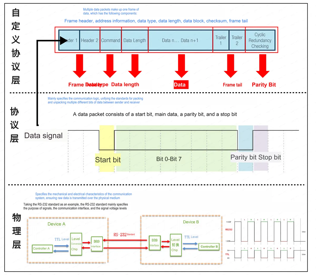
Differences and Connections Between UART-TTL, RS485 and RS422
For serial communication, it can be divided into the protocol layer and the physical layer:
- Protocol Layer: It mainly specifies the contents such as the data packet structure, error detection and correction, as well as rate matching and synchronization for serial communication.
- Physical Layer: It mainly specifies the functions of signals, interfaces, level standards and other relevant contents.
Here, depending on the different logic level standards used for communication, serial communication can be divided into different Communication Protocols such as TTL standard, RS-232 standard, CMOS standard, RS422, and RS485.
The so-called logic level refers to a state capable of generating a signal, which is usually represented by the potential difference between the signal and the ground wire. The fluctuation range of the logic level is determined by the characteristics of different devices in the logic circuit; digital circuits are designed based on the electrical signals "0" and "1", and there are different integrated circuit devices in logic circuits. In actual operation, these devices require a specific voltage and current standard to determine whether their electrical signal is '0' or '1', so this standard is called the logic level.
In common serial communication, the TTL level standard is frequently used; ideally, 5V represents binary logic 1 and 0V represents logic 0. To enhance the long-distance transmission capability and anti-interference performance of serial communication, RS422 uses -15V to represent logic 1 and + 15V to represent logic 0.
Different from TTL and RS422 which determine logic 1 or logic 0 through the high and low levels of a single wire, RS485 uses the potential difference between two differential lines as the identifier for logic 1 or logic 0, thus overcoming the drawback that TTL level common-ground mode transmission is prone to interference. The biggest feature of RS485 communication is that its transmission speed can reach above 10Mb/s, the transmission distance can reach about 3000 meters, and meanwhile its anti-interference performance is also stronger than that of other communication methods.
1.1.4.2 Custom Protocol Frame Format
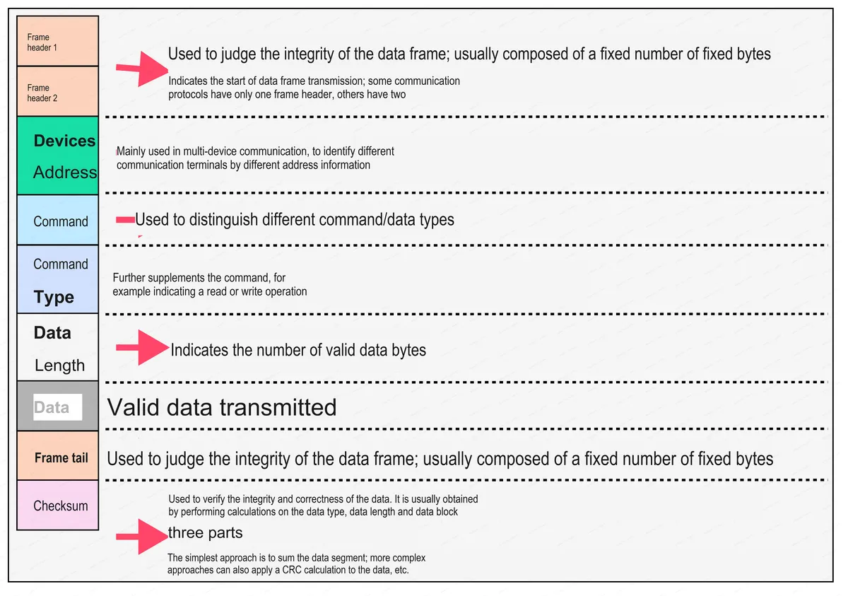
For custom protocol frames, they typically consist of the following components: frame header, frame tail, address information, data type, data length, data block, check code, etc. The common format of a custom protocol frame is as follows:
1.1.4.3 Packaging and Unpacking of Custom Protocols
Here, encapsulation refers to adding identifiers (such as frame header, device address, command, command type, data length, frame tail, check code, etc.) to the start and end of the data to be sent, while decapsulation refers to filtering out the parts other than the sent data from the received data frame for display.
The common process for data unpacking is as follows:
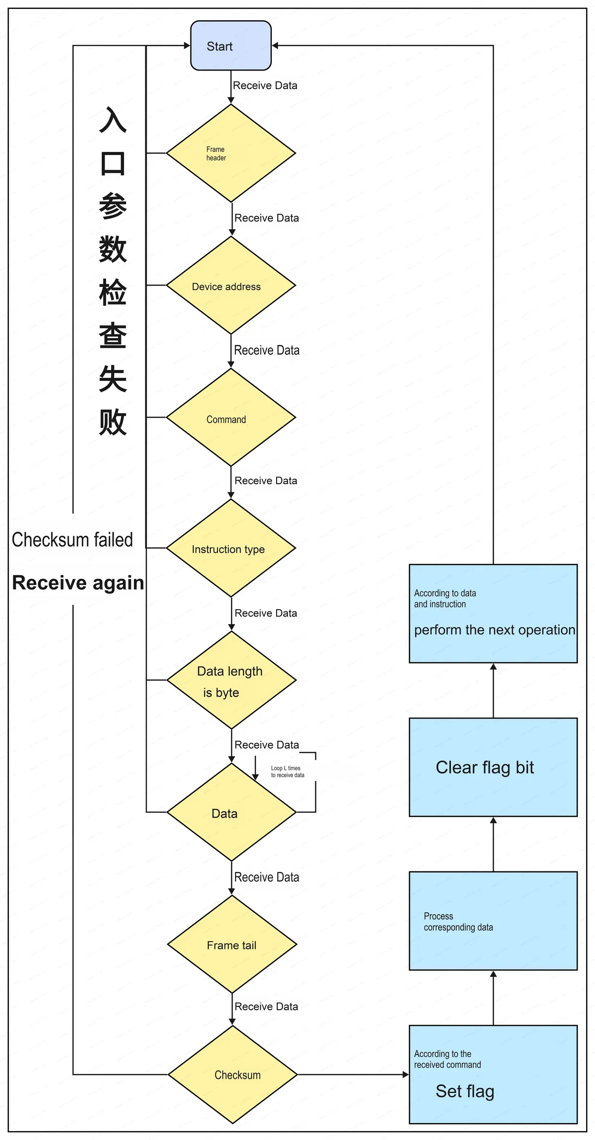
After receiving each data packet of a data frame, we need to perform a check on it:
- Upon receiving the first data, determine whether it is a frame header; if it is a frame header, receive the next data, set the flag indicating that the frame header has been fully received, and store the frame header in a pre-declared list or other data structure for caching, so as to facilitate further processing of the data after the reception is completed; otherwise, do not set the flag indicating that the frame header has been fully received, and re-determine whether the next received data is a frame header.
- When receiving function codes (i. e., device addresses, command types, instructions, etc.), the process is the same as above: first, determine whether the data falls within one of the parameter ranges preset for the function code, which is the check of entry parameters (for example, there are only 3 types of commands, namely 0x51,0x52, and 0x53, and it is necessary to determine whether the received command is one of the three). If the data belongs to one of the parameter ranges preset for the function code, set the flag indicating that the function code has been fully received, and store it in the data structure for buffering; otherwise, restart the reception from the frame header.It should be particularly noted here that, for the function code of data length, it is necessary to judge the data length range; otherwise, a memory overflow problem may be caused by a reception error of the data length range (for example, the received data length exceeds the preset list size).
- After the verification is correctly completed, extract the data and instructions from the data structure used for caching, and perform the next operation based on the data and instructions.
1.1.5 Serial Port Flow Control
"Stream" refers to "data stream". When the rate between the sender and the receiver does not match (e. g., the processing speed of the receiver is slower than that of the sender), the receiver's buffer will "overflow", resulting in data loss. The core of "flow control" is to "enable the sender to dynamically adjust its sending behavior according to the status of the receiver".
- Hardware flow control: Controlled via dedicated pin signals, the most commonly used one is
RTS/CTS(Request To Send / Clear To Send) flow control. Its principle is that "the receiver usesCTSto inform the transmitter 'whether it can send data', and the transmitter usesRTSto request 'whether it is allowed to send'".- The definitions of common signals are as follows:
RTS(Request To Send): The sender requests the receiver for "permission to send"(for example, whenMCUsends aRTSlow level to the "serial port module", it means "I am ready to receive, you can send").CTS(Clear To Send): The receiving end responds with a "permission to send" signal to the transmitting end (for example, when aMCUreceives aCTSlow level signal from a serial port module, it means "I am ready to transmit, you can receive").
- Working Logic: The receiving end will set a "high buffer threshold (e. g., 75% buffer occupancy)" and a "low buffer threshold (e. g., 25% buffer occupancy):"
- When the receiver buffer is "≥ high threshold", set
RTSto high level (meaning "My buffer is almost full, stop sending data"); when the transmitter detects the high level ofRTS, it stops transmission. - When the receiver buffer is "≤ low level", set
RTSto low level (meaning "my buffer has space now, continue sending"); when the transmitter detects the low level ofRTS, it resumes transmission.
- When the receiver buffer is "≥ high threshold", set
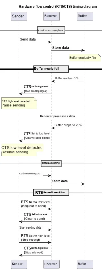
- Note: For hardware flow control, "hardware at both communication ends must support
RTS/CTSpins", and "cross connection" is required during wiring (e. g.MCU'sRTSconnects to the serial port module' sCTS,MCU'sCTSconnects to the serial port module' sRTS).
- The definitions of common signals are as follows:
- Software flow control: Controlled by special characters. When hardware does not support flow control pins, it is implemented via
XON/XOFFcharacters (XONmeans "continue transmission",XOFFmeans "stop transmission").- Working Logic :
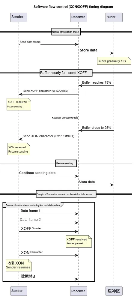
- When the receiver buffer is "≥ high watermark", it sends to the transmitter the XOFF character (decimal 19, or Control-S); upon receiving XOFF, the transmitter immediately stops transmission.
- When the receiver buffer is "≤ low threshold", it sends a XON character (decimal 17, or Control-Q) to the transmitter; upon receiving XON, the transmitter immediately resumes transmission.
- Working Logic :
1.1.6 Data Validation
During transmission, electromagnetic interference, line loss and other factors may cause " data bit errors ". "Data check" enables the receiving end to "detect and even correct errors" by "adding redundant information". Common check methods are as follows:
- Parity Check
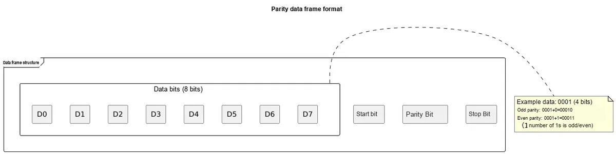
- Principle: append one parity bit after the "valid data", so that the number of 1s in the combination of "valid data + parity bit" conforms to the predefined odd/even parity rule.
- Even parity: In the combination of "valid data + parity bit", the number of 1s is even (e. g., the valid data "0001" contains one 1, so the parity bit should be 1 → the total number of 1s is 2, which is even).
- Odd parity: In the combination of "valid data + parity bit", the number of 1s is odd (e. g., the valid data "0001" contains one 1, so the parity bit should be 0 → the total number of 1s is 1, which is odd).
- Features: It can only "detect 1-bit errors"; if multiple data bits go wrong simultaneously, it may fail to detect the errors, and it cannot "correct errors" but only "detect errors".
- CRC Check (Cyclic Redundancy Check)
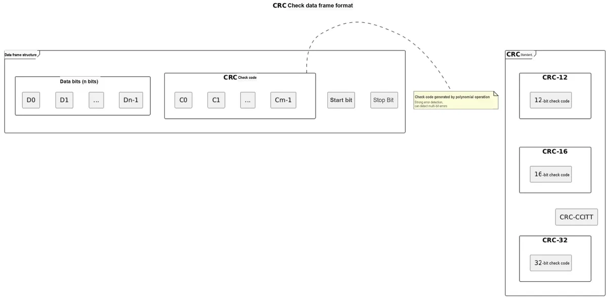
- Principle: Based on the "division remainder" principle, a "polynomial operation" is performed on the "valid data" to generate
CRCcheck code (sent along with the data); the receiver repeats the same operation on the "received data", and if the "calculatedCRC" does not match the "receivedCRC", it is determined that a "data error" has occurred. - Common standards:
CRC-12(12-bit check code),CRC-16(16-bit),CRC-CCITT(16-bit, commonly used in the communication field),CRC-32(32-bit, commonly used for file verification). - Features: It has strong error detection capability, which can detect "multi-bit errors and burst errors", but it can only "detect errors" and cannot "correct errors".
- Principle: Based on the "division remainder" principle, a "polynomial operation" is performed on the "valid data" to generate
- XOR Checksum (XOR Check)
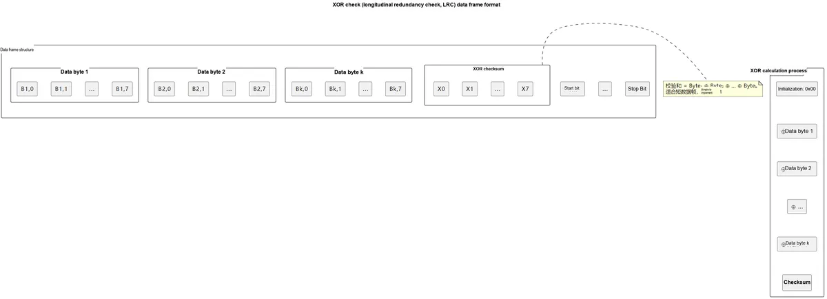
- Principle: Perform a byte-by-byte operation on "all bytes of the data word" XOR operation to generate a 1-byte "checksum"(also known as "Longitudinal Redundancy Check, LRC").
- Example: the data words are
Byte₀, Byte₁, Byte₂, …, Byteₙ, and the checksum =Byte₀ ⊕ Byte₁ ⊕ Byte₂ ⊕ … ⊕ Byteₙ(where "⊕" denotes the XOR operator). - Features: It is easy to implement and suitable for "short data, low power consumption" scenarios; however, its error detection capability is weaker than that of CRC, so it is mostly used in occasions where the reliability requirement is not extremely high.
1.1.7 The "pipelining" approach to improving communication throughput
The "throughput" of serial communication refers to "the amount of data transmitted per unit time". The traditional throughput serial process of "master transmits → slave receives → slave replies → master receives" generates a large amount of idle time due to "waiting for replies", resulting in low efficiency. Through "pipelining" transformation, the throughput can be significantly improved.
- Traditional Process vs. Assembly Line Process (Time Dimension Comparison)
- Traditional process: The sender (master) sends "Frame 1" → the receiver (slave) receives "Frame 1" → the slave processes "Frame 1" → the slave replies with "Frame 1" → the master receives the reply → then sends "Frame 2". ..(there is a large amount of "red idle time" between each frame).
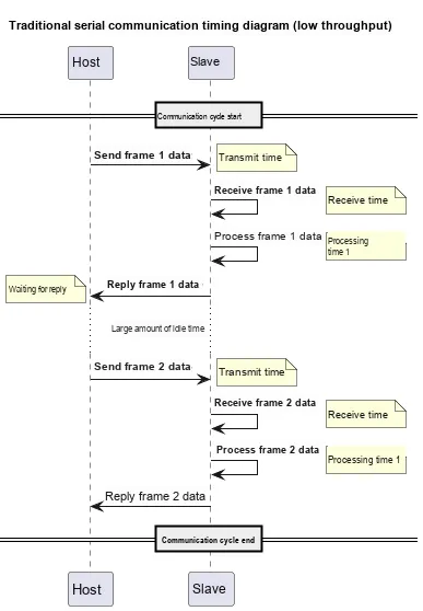
- Pipelining Process: The transmitting end does not need to wait for "the reply of the previous frame to be completed", and can continuously send "Frame 1, Frame 2, Frame 3.. ." as long as "the interval between adjacent frames is sufficient"; the receiving end, on the other hand, "receives new frames while processing the received frames"(similar to the "instruction pipelining" of a CPU).
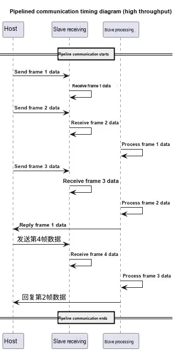
- The implementation logic of the pipeline: "caching + task parallelism". To achieve parallelism between "receiving" and "processing", at least two cache spaces are required:
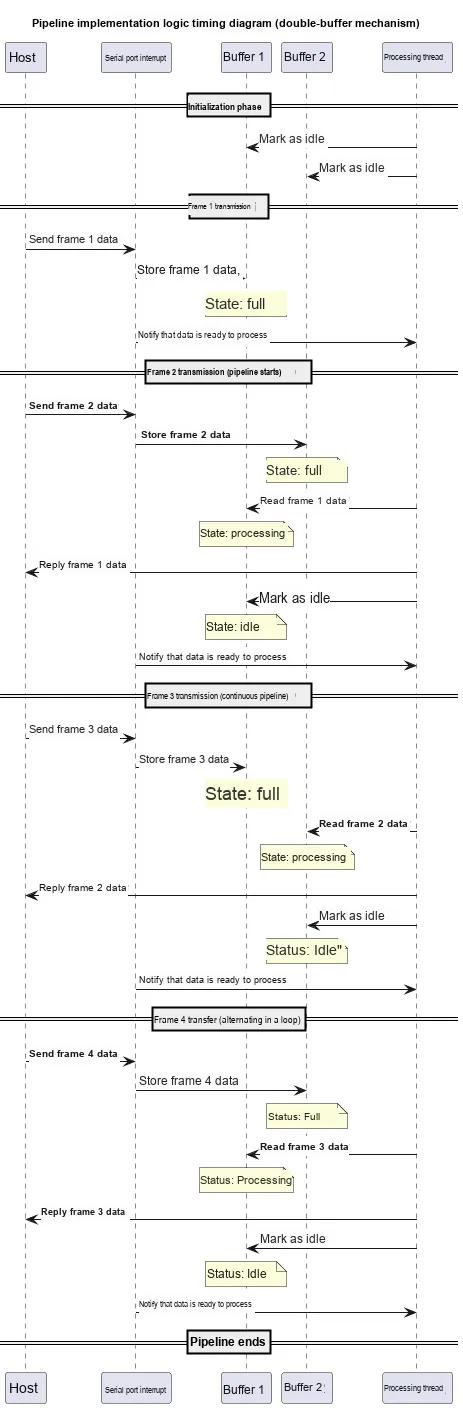
- While "Buffer 1" is "receiving new data frames", "Buffer 2" can simultaneously "process the received old data frames".
- The transmitter may also send the next frame *without waiting for the receiver to finish replying*, as long as the *inter-frame spacing* allows the receiver to *normally trigger the interrupt and process the data*.
For higher efficiency, you can also manage multiple buffers via queues (e. g., in real-time systems like μC/OS-II, manage multiple buffers with the mechanism of " memory management + queue service "), and it even supports " priority preemption for urgent tasks "(inserting urgent communication tasks at the head of the queue for priority processing).
1.2 Basic Structure and Concepts of UART
The UART serial port peripheral on the Raspberry Pi Pico is the "serial communication unit" on the Raspberry Pi Pico, which is specifically responsible for communication between the Pico and other devices (such as computers, sensors, display screens) using the serial port protocol:
- Data transmission: The parallel data inside Pico is converted into serial data via UART and then transmitted to external devices;
- Data reception: The serial data from external devices is converted into parallel data via UART and then transmitted to the interior of the Pico.
The serial port peripheral is not an independently operating unit, but a working module that needs to cooperate with other internal components of the Pico:
- CPU: responsible for issuing instructions and processing final data;
- UART peripheral: responsible for serial-parallel conversion of data and serial codec between different devices;
- AMBA APB bus: The CPU controls the UART peripheral and transmits data via the AMBA APB bus;
- FIFO Memory: The data received and transmitted by the UART can be buffered by the FIFO memory, which supports independent storage of up to 32 bytes of data in both transmission and reception modes.
FIFO memory
FIFO (First Input First Output) simply refers to the first-in, first-out principle. A FIFO memory is a dual-port buffer that operates on the first-in, first-out mechanism, meaning the first data item entering the memory is the first to be moved out; one of the ports serves as the input port of the memory, and the other acts as the output port of the memory.
FIFO memory serves as a buffering component in systems, and it mainly has the following functions:
- Cache the continuous data stream to prevent data loss during machine entry and storage operations;
- Centralizing data for stack pushing and storage can avoid frequent bus operations and reduce the burden on the CPU.
- Allows the system to perform DMA operations to increase data transmission speed. This is a critical point: if DMA operations are not adopted, data transmission will fail to meet the specified requirements, and the CPU burden will be greatly increased, making it impossible to complete data storage operations concurrently.
The serial port peripheral supports the following functions:
- Programmable baud rate generator: It generates a clock signal matching the target communication rate to implement "baud rate synchronization" between the UART and external devices (e. g., 9600,115200, etc.), which serves as the foundation of asynchronous communication.
- It provides functions similar to the industry-standard 16C650 UART device: It complies with the universal UART hardware protocol, ensuring that the UART of Pico can directly communicate with mainstream UART devices such as computers and sensors, and boasts excellent interoperability;
- When the system clock is 125MHz, the maximum supported rate is 7.8Mbps: this refers to the theoretical upper limit of the UART bandwidth; the low-speed communications commonly used in daily scenarios (e. g., 9600bps) are far below this value, which can meet the transmission requirements of most use cases;
- Independent maskable interrupts from reception, transmission, modem mode and error conditioning: The UART provides independent interrupt sources for events such as "reception complete, transmission complete, modem status change, and communication errors"; the CPU can mask specific interrupts via registers to only respond to required events, thus reducing unnecessary CPU resource consumption.
- Send a DMA request to the DMA controller: The UART can initiate a "data transfer request" to the DMA controller to trigger the DMA to complete "data transfer between the FIFO and the memory"(without CPU intervention), thus reducing the load on the CPU;
- It features a programmable hardware flow control mechanism: It implements flow control between the transmitter and receiver via the nUARTCTS (Clear to Send) and nUARTRTS (Request to Send) pins: when the receiver's buffer is full, it notifies the transmitter to suspend transmission through the CTS pin; once the receiver is ready, it re-enables transmission via CTS to prevent data overflow.
DMA-Direct Memory Access
DMA is the "data transfer controller" inside the Pico, whose core feature is that it can directly complete data transfer between "memory and peripherals" as well as "memory and memory" without the participation of the CPU.
- In the traditional approach, the CPU has to manually read data from peripherals and write it to memory (or perform the reverse operation), during which the CPU cannot execute other tasks;
- With the aid of DMA, the UART can be triggered via a "DMA request" to automatically complete data transmission between the "FIFO and memory", thereby freeing up CPU resources.
When the UART receives data, if an abnormality occurs, it will mark and protect the data via registers:
- If a frame error, parity error, or break error occurs: the UART will set the corresponding "error flag bit" in the register, and simultaneously store the erroneous data into the receive FIFO for subsequent processing by the CPU;
- If a FIFO overflow occurs (the amount of received data exceeds the FIFO capacity): the UART will immediately set the "overflow flag bit" and stop receiving new data to prevent the valid data already stored in the FIFO from being overwritten.
1.2.1 UART Peripheral Structure
The basic structural block diagram of the serial port peripheral of the Raspberry Pi Pico is as follows:
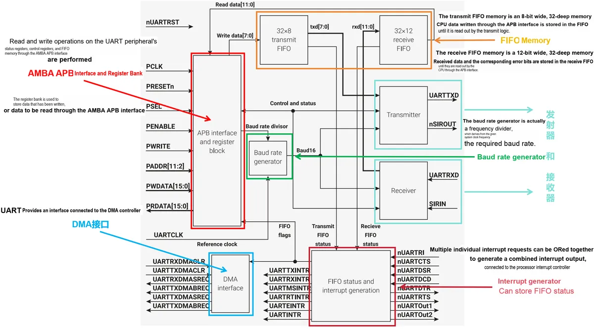
The block diagram above illustrates the "internal working pipeline" of the UART serial peripheral of the Raspberry Pi Pico, where each module has a clear division of labor to jointly implement serial communication:
- Core control entry:
AMBA APBinterface and register file, which serves as the only window for communication betweenCPUandUART:AMBA APBinterface:The CPUuses this interface to send "control commands"(such as setting the baud rate) to theUART, write "data to be transmitted", or read "received data" and "UART operating status".- Register file: It stores the control parameters (such as baud rate configuration), status information (such as whether the FIFO is full) and temporary data of the UART — it is equivalent to the "control panel + temporary notepad" of the UART.
- Clock Synchronization Core: Baud Rate Generator
- It serves as the "metronome" of
UART, responsible for generating clock signals that match the target baud rate; - Working Logic: Starting from the system clock (
UARTCLK), theBaud16clock (used in normal mode) is generated through frequency division —Baud16is a clock that runs at 16 times the target baud rate (for example, if the target baud rate is 9600, Baud16 will be 153600); - Function: The transmitter/receiver divides
Baud16by 16 to obtain a clock of "1x baud rate", which is used to synchronize data transmission/reception (during reception, sampling can be performed in the middle of each data bit to reduce level judgment errors).
- It serves as the "metronome" of
- Data Buffer:
FIFOMemory:- It is divided into transmit
FIFOand receiveFIFO, which is the key to alleviating the "rate mismatch betweenCPUandUART". - Transmit
FIFO(32×8 bits): The CPU first writes the 8-bit data to be transmitted into this FIFO, and the transmitter fetches the data byte by byte from the FIFO and converts it into serial data for transmission; even if the CPU has a low processing speed, the data can be temporarily stored without being lost; - Receive
FIFO(32×12 bits): After the receiver converts the received serial data into parallel data, it stores the data together with the "error flag bits"(such as frame error) here (the 12 bits consist of 8 data bits + 4 error bits) for the CPU to read, so as to prevent data loss caused by the CPU being busy when the receiver receives data.
- It is divided into transmit
- Data Transceiving Execution: Transmitter & Receiver
- This is the "execution unit" of the UART, which performs serial-to-parallel conversion;
- Transmitter: Reads parallel data from the transmit FIFO, and under the synchronization of the
Baud16clock, converts the data bit by bit into a serial signal, and sends it out from theUARTTXDpin; - Receiver: Receives serial signals from the
UARTRXDpin, and under the synchronization of theBaud16clock, converts the signals bit by bit into parallel data and stores them in the receive FIFO (while marking error status).
- Status Notification: Interrupt Generator
- It acts as the "status announcer" of the UART;
- Collect signals such as the status of FIFOs (e. g., transmit FIFO empty, receive FIFO full), transceive events (e. g., transmission complete, reception complete), and communication errors (e. g., frame error);
- These signals are subjected to an "OR operation"(i. e., triggered if any one of the events occurs) to generate an interrupt signal that is sent to the CPU for timely processing (such as reading received data and handling errors).
- Efficient Data Transfer: DMA Interface
- This serves as the "connection interface" between the UART and the DMA controller;
- When the data in the FIFO reaches a certain amount, the UART will initiate a "transfer request" to the DMA through this interface;
- Upon receiving a request, DMA will automatically transfer data between the transmit FIFO and the memory as well as between the receive FIFO and the memory, without requiring CPU intervention throughout the process, thus reducing the CPU load.
The overall workflow is as follows:
- Transmission Flow: CPU →(via APB interface) write data to the transmit FIFO → baud rate generator generates Baud16 clock → transmitter fetches data from FIFO → converts to serial data and outputs via UARTTXD;
- Reception Process: UARTRXD receives serial data → the receiver (using the Baud16 clock) converts it to parallel data and appends a parity error flag → the result is stored in the receive FIFO → the interrupt generator notifies the CPU → the CPU (via the APB interface) reads the data from the receive FIFO.
Here, the baud rate generator provides two clock signals, IrLPBaud16 and Baud16:
IrLPBaud16: This is the clock signal provided to the serial port transmitter and receiver, which is used in the IrDA infrared mode and will not be elaborated here.Baud16: This is a clock signal provided to the UART transmitter and receiver. It generates an integer baud rate reference clock at 16 times the baud rate, with a pulse width of one UARTCLK clock cycle. Used in normal mode, this clock signal is divided by 16 to generate the clock for the UART transmitter.
1.2.2 Clock Configuration of UARTCLK
The frequency of UARTCLK shall be adapted to the range of the baud rate:
16 × maximum baud rate ≤ UARTCLK frequency ≤ 6 × 65535 × minimum baud rate
For example, when the baud rate ranges from 110 to 460800, the UARTCLK frequency must be between 7.3728 MHz and 115.34 MHz.
Meanwhile, the ratio of the frequency of UARTCLK to the frequency of PCLK must be less than or equal to 5/3, that is:
The frequency of UARTCLK ≤ 5/3 × the frequency of PCLK
For example, in UART mode, when UARTCLK is 14.7456MHz and a baud rate of 921600 is to be generated, PCLK must be greater than or equal to 8.85276MHz. This ensures that the UART has sufficient time to write the received data into the receive FIFO.
1.2.3 UART Peripheral Operations
The base addresses of the UART0 and UART1 registers are 0x40034000 and 0x40038000 respectively.
The UART peripheral can be controlled by writing to the UARTLCR register, which contains 30 bits internally. It should be noted that we need to access the UARTLCR_H, UARTIBRD and UARTFBRD registers externally via the APB bus interface to write to the UARTLCR register, where:
- UARTLCR_H Register:
It is mainly used to define the valid data to be transmitted, the number of data bits, stop bits, parity bit, transmission stream mode, and disconnection.
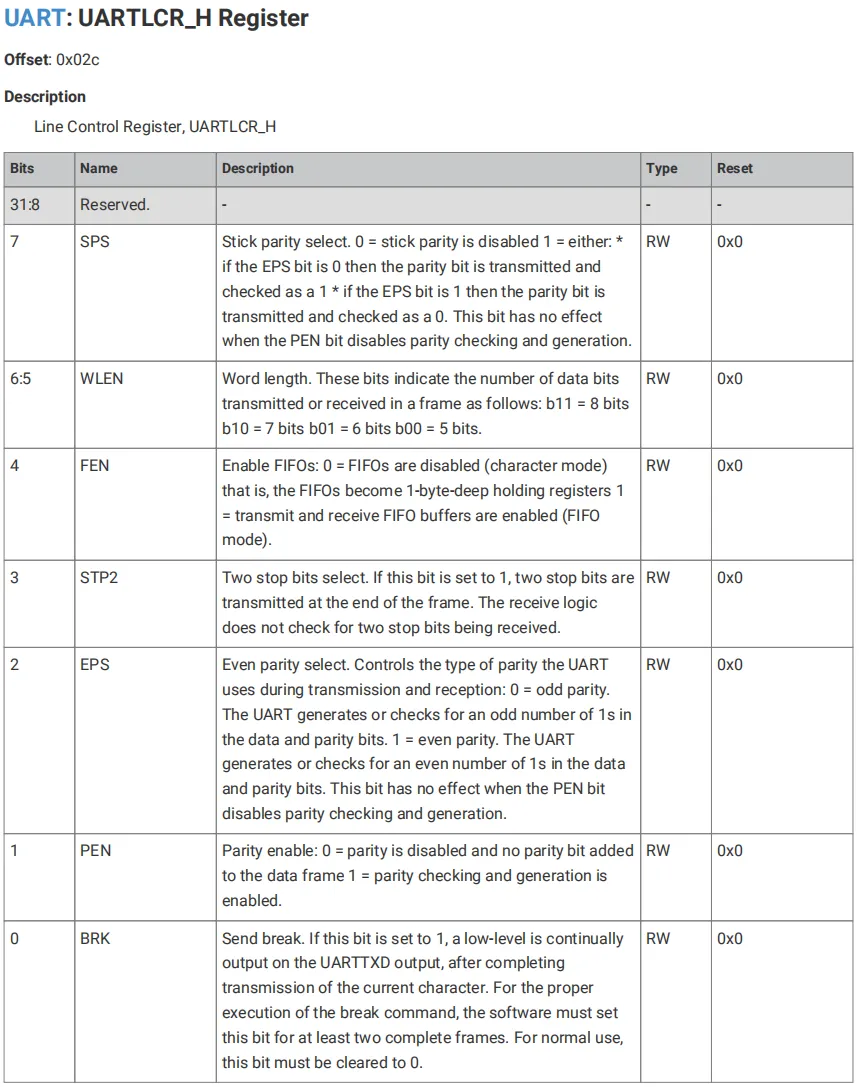
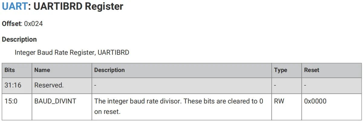
- UARTIBRD Register: defines the integer part of the baud rate divisor factor
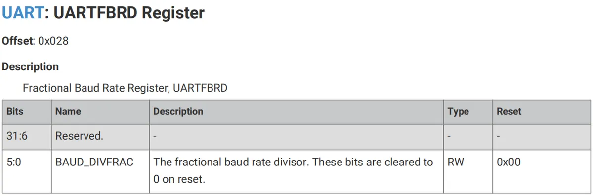
- UARTFBRD Register: defines the fractional part of the baud rate divisor.
1.2.3.1 Set Baud Rate
Setting the baud rate mainly involves configuring the baud rate divisor factor (hereinafter referred to as the baud rate factor). The baud rate factor is a 22-bit number consisting of a 16-bit integer part and a 6-bit fractional part. The fractional baud rate factor allows any clock with a frequency greater than 3.6864 MHz to be used as UARTCLK while still being able to generate all standard baud rates.
The 16-bit integer baud rate factor is loaded via the UARTIBRD register, and the 6-bit fractional baud rate factor is loaded via the UARTFBRD register.
The relationship between the baud rate factor and the UARTCLK clock is as follows:
BRD = BRDI + BRDF = UARTCLK/(16×Baud Rate), where BRDI is the integer part of BRD, BRDF is the fractional part separated by the decimal point, and UARTCLK is the system clock connected to the UART.

1.2.3.2 Error Bit
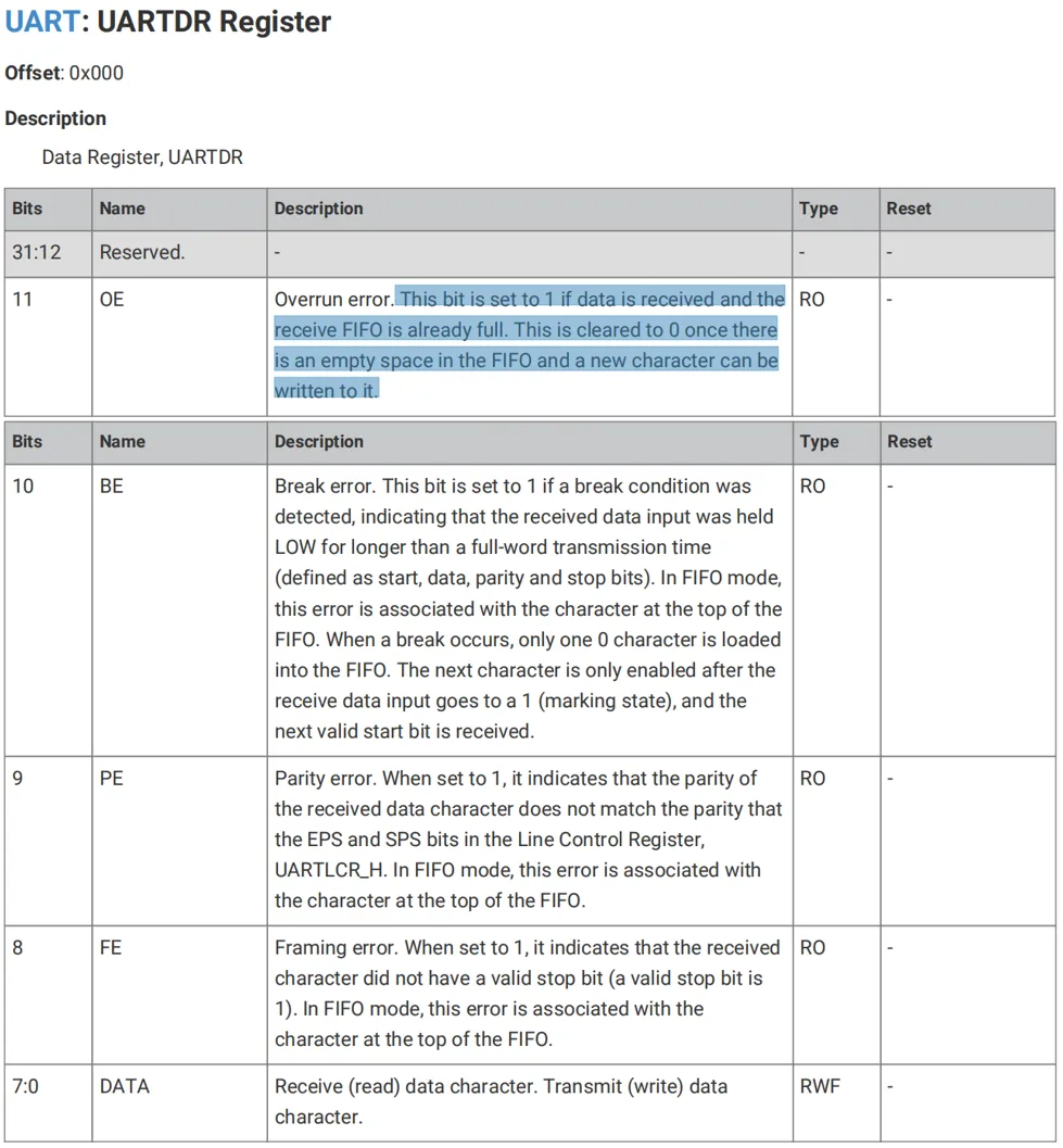
Three error bits are stored in bits [10:8] of the receive FIFO memory and are associated with a specific character. There is also an additional error indication, the overrun error, which is stored in bit 11 of the receive FIFO.
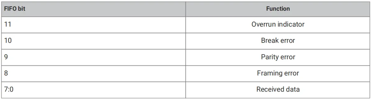
When the FIFO memory is full, the overrun flag is set to indicate an overrun error, after which the next data will be directly written into the shift register of the UART (the shift register is mainly used for serial-parallel conversion of serial port data) and overwrite the data currently stored in the UART shift register. When an empty slot becomes available in the receive FIFO and another character is received, the state of the overrun bit, together with the received character, is copied into the receive FIFO, after which the overrun state will be cleared.
Regarding the reading of error bits, it is mainly accomplished by accessing the UARTDR register:
1.2.3.3 System Diagnosis and Loopback Test
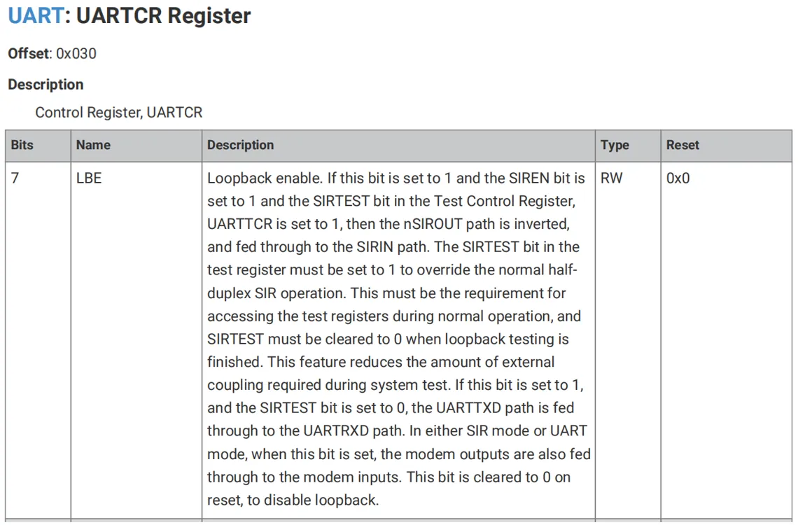
By setting the LBE bit of the UARTCTL register, the UART can be configured into internal loopback mode for diagnostic or debugging purposes. In loopback mode, the transmit data output from UARTxTXD will be received by the UARTxRXD input. Note that the LBE bit should be set before the UART is enabled.
1.2.3.4 FIFO Operations
The UART has two independent FIFO memories: a separate 32×8 Tx transmit FIFO memory and a 32×12 Rx receive FIFO memory. Both FIFOs are accessed via the UARTDR register. A read operation on the UARTDR register returns a 12-bit value consisting of 8 data bits and 4 error flag bits, while a write operation places 8-bit data into the transmit FIFO.
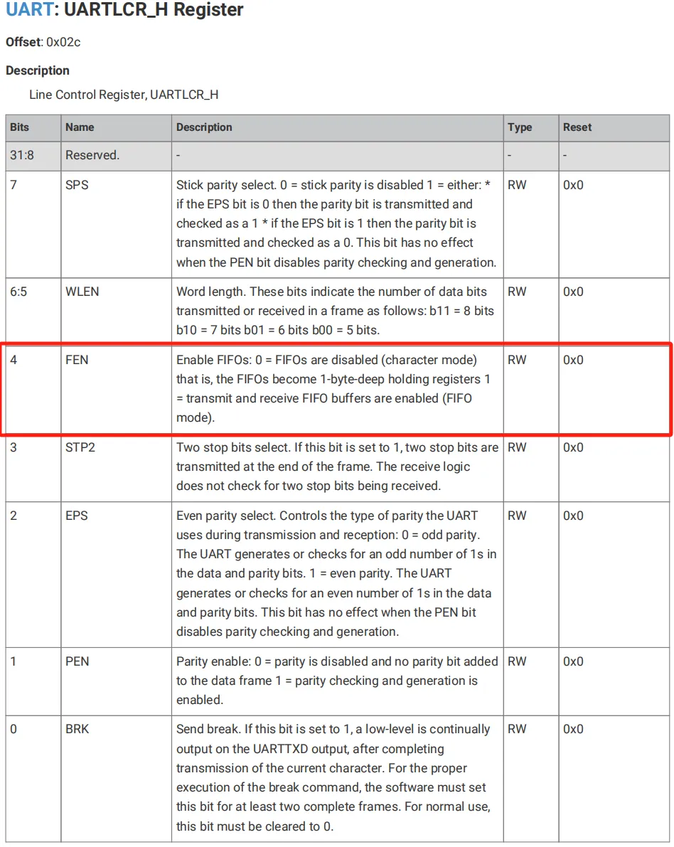
We can control the operating mode of the FIFO by setting the FEN bit in the UARTLCR_H register:
- FEN = 0: FIFO is disabled, operates in character mode, and remains a 1-byte deep register
- FEN = 1: FIFO is enabled, the device operates in FIFO mode, and the transmit and receive FIFO buffers are enabled
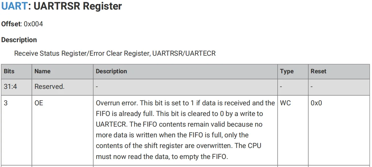
The status of the FIFO can be monitored via the UART Flag (UARTFR) register and the UART Receive Status (UARTRSR) register to check whether it is empty, full, or in an overflow state.
The UARTFR register contains empty and full flag bits (TXFE, TXFF, RXFE, and RXFF bits):
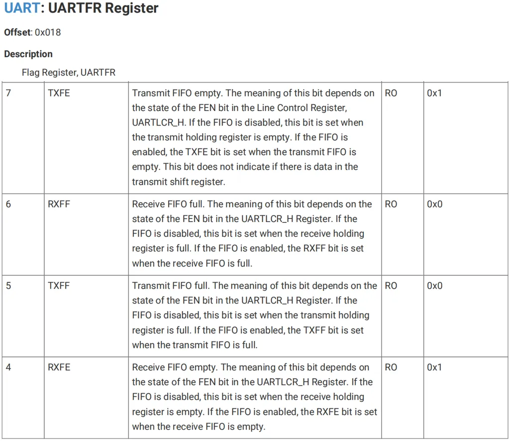
If FIFO is disabled, the empty and full flag bits will be set according to the status of the 1-byte depth register.
The UARTRSR register indicates the overflow status via the OE bit:
1.2.4 UART Transmit and Receive Process
1.2.4.1 UART Data Transmission Process
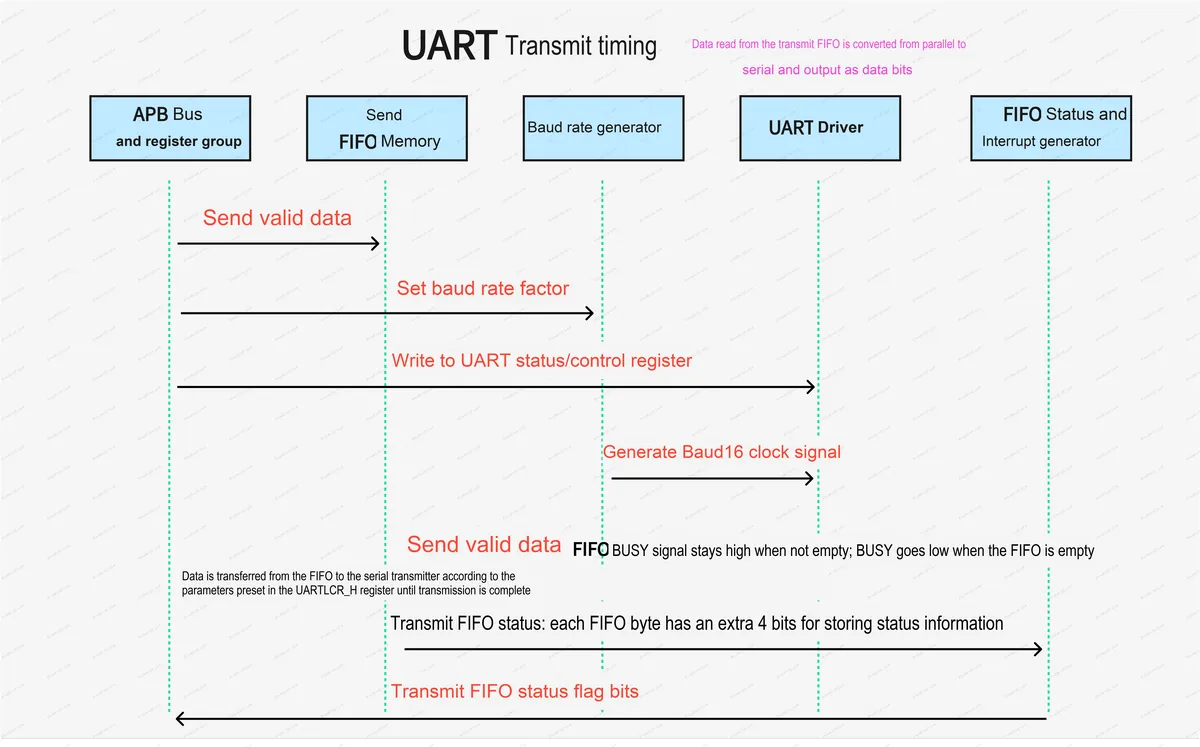
- The APB bus can access the status/control registers and store the information to be transmitted into the transmit FIFO memory;
- The baud rate generator obtains the baud rate division factor from the APB bus and the register block, and generates the internal clock Baud16, whose frequency is 16 times the baud rate.
- The UART transmitter is controlled by the status/control register, and transmits the content in the transmit FIFO memory one by one with Baud16 as the clock source;
- The FIFO status and interrupt generator generates corresponding FIFO flag bits and interrupt signals according to the content of the FIFO memory.
1.2.4.2 UART Data Receiving Process
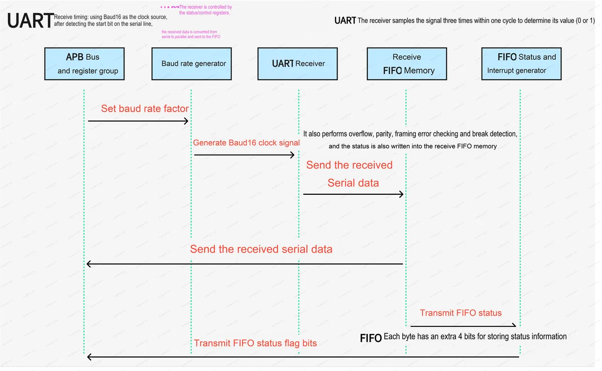
- The UART receiver is controlled by the status/control register, uses Baud16 as the clock source, and stores the received information in the receive FIFO memory;
- The APB bus can obtain the read value by reading the receive FIFO
1.2.5 UART hardware flow control function
We can control the serial data flow by using the nUARTRTS output and nUARTCTS input signals:
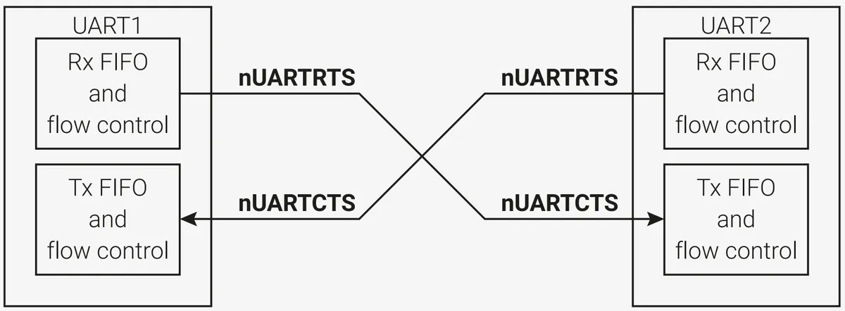
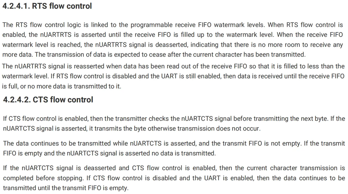
When RTS flow control is enabled, the nUARTRTS output signal will be pulled high (inactive) once the receive FIFO memory is filled to the set buffer depth; prior to this, the nUARTRTS output signal will remain at low level (active) to indicate the FIFO status. When CTS flow control is enabled, the UART transmitter will only start transmitting data after receiving a low-level signal on the CTS pin from the external device.
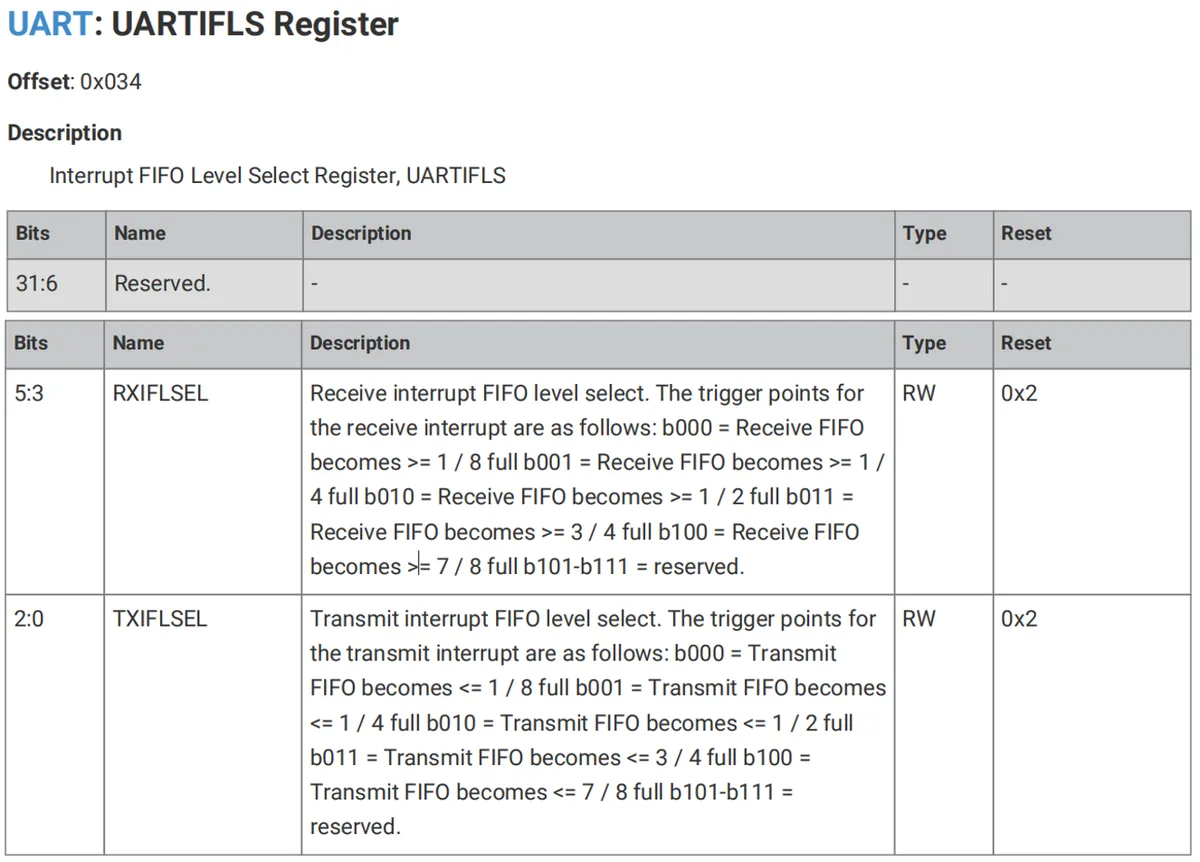
The buffer depth of the FIFO memory can be configured by setting the UARTIFLS register:
The RTSEn and CTSEn bits in the UARTCR control register can be used to select hardware flow control:
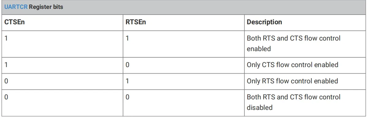
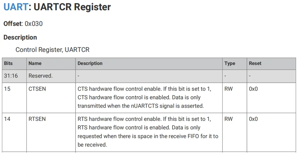
It should be noted that once RTS flow control is enabled (i. e., the RTSEN bit is set to 1), the software can no longer use the RTSEn bit in the UARTCR control register to control the status of nUARTRTS, nor can it change the output value of nUARTRTS.
Serial port flow control function
The "stream" mentioned here refers to a data stream. When data is transmitted between two serial ports, data loss often occurs if the communication parties have mismatched rates. For example, in the communication between a desktop computer and a single-chip microcontroller, if the data buffer of the receiving end is full, the subsequently sent data will be lost. This problem was particularly prominent when data was transmitted via MODEM in early networks. Therefore, the concept of flow control is introduced: when the data processing speed of the receiving end is insufficient, it sends a signal of "no longer receiving", and the sending end will stop transmitting data until it receives the signal of "resume transmission" to send data again.Therefore, flow control can manage the data transmission process to prevent data loss. The two commonly used types of flow control are hardware flow control (including RTS/CTS, DTR/CTS, etc.) and software flow control XON/XOFF (Continue/Stop), which are described separately below:
- hardware flow control
Common hardware flow control methods include RTS/CTS flow control and DTR/DSR (Data Terminal Ready/Data Set Ready) flow control, with the former being the dominant one in practical applications. The functions of the RTS/CTS pins are as follows:
- RTS (Request To Send)- When the RTS pin of the module outputs a low level, it indicates that the module has started preparing to receive data.
- CTS:(Clear To Send)- The module can only transmit data when the external MCU pulls the CTS pin of the module to a low level.
- Software Flow Control
Since hardware flow control is subject to usage constraints on both hardware and software, software flow control is used as an alternative in some scenarios. Software flow control is generally implemented via the special characters XON/XOFF. Its working principle is as follows: when the data volume in the input buffer of the receiving end exceeds the set high threshold, the receiving end sends an XOFF character (decimal 19 or Control-S, which should be detailed in the device programming manual) to the sending end; upon receiving the XOFF character, the sending end immediately stops transmitting data;When the amount of data in the input buffer of the receiving end falls below the set low threshold, it will send an XON character (decimal 17 or Control-Q) to the data transmitting end, and the transmitting end will immediately start transmitting data upon receiving the XON character.
1.2.6 DMA Interface of UART
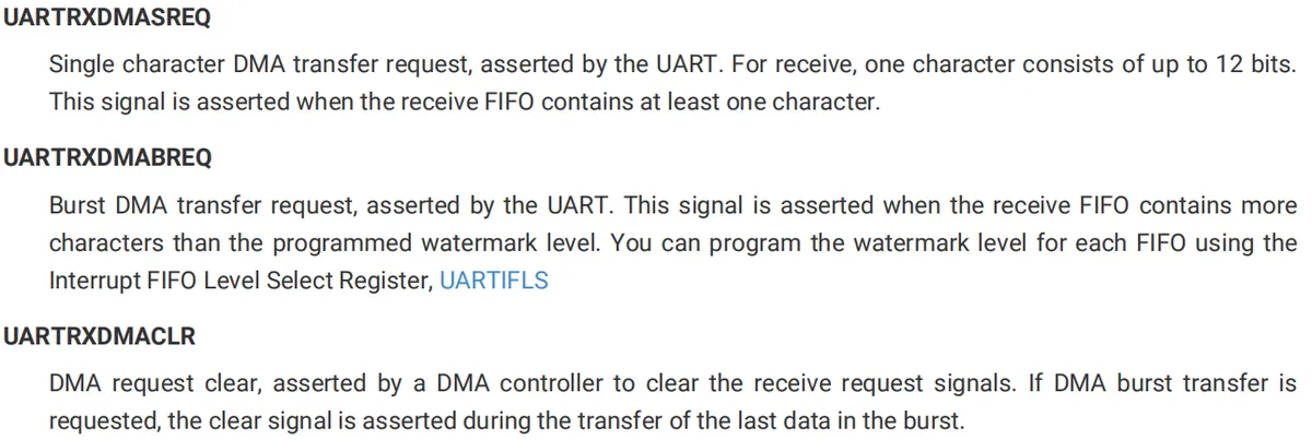
The UART provides an interface to the DMA controller, with separate transmit and receive channels. DMA operations for the UART are initiated via the UART DMA Control (UARTDMACR) register. DMA performs data transfers following a DMA request signal — which is asserted either after the peripheral completes an event or when the peripheral is ready for operation. This DMA request signal is generated by peripheral registers associated with data transfer; these registers hold the peripheral’s current operating status, and issue a request to DMA once predefined conditions are met.
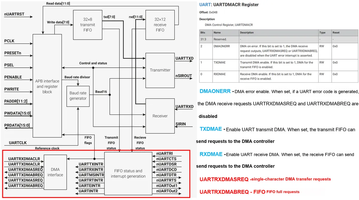
The DMA requests that can be generated include:
- For the receiving end:
- For the transmitting end:
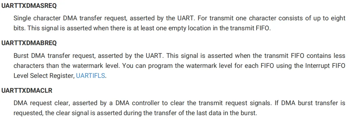
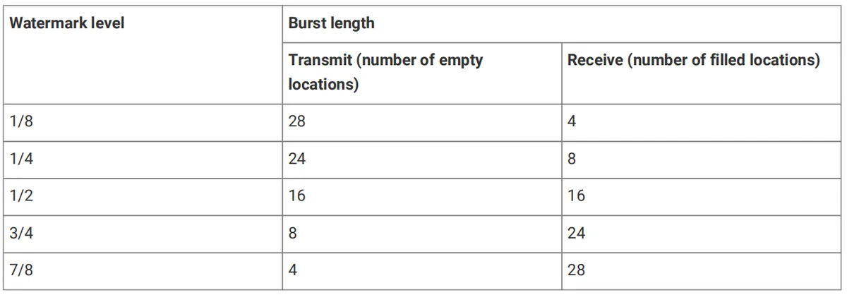
Simply speaking, for the receiving end, as long as there is data in the receive FIFO, a single transfer request UARTRXDMASREQ will be generated; when the data volume in the receive FIFO is greater than or equal to the UARTIFLS register-configured FIFO buffer depth, a burst transfer request UARTRXDMABREQ will be generated;For the transmitter side, as long as there is at least one empty slot in the transmit FIFO, a single transfer request UARTTXDMASREQ will be generated; and as long as the number of characters contained in the transmit FIFO is less than the FIFO trigger level, a burst request UARTTXDMABREQ will be generated. For both the receiver and transmitter sides, the DMA controller can also generate UARTTXDMACLR and UARTRXDMACLR requests to clear the DMA data transfer request signals after data transmission is completed.
Meanwhile, respective DMA requests can occur simultaneously, and both single and burst transfer requests are automatically processed by the DMA controller; whether data transfer is performed in single mode or burst mode depends on the set FIFO memory buffer depth and the amount of data in the FIFO.
1.2.7 UART Interrupts
1.2.7.1 UART Interrupt Types
When the following conditions are detected, UART will generate an interrupt:
- Modem status signal change: generate
UARTMSINTRinterrupt - Receive buffer full: generates
UARTRXINTRinterrupt - Transmit FIFO empty: generates
UARTTXINTRinterrupt - Reception timeout: generates
UARTRTINTRinterrupt - Receive error: A
UARTEINTRinterrupt is generated, including the following error conditions:- Frame Error
- Parity Check Error
- Overflow Error
- Break Error
Interrupt Type | Occurrence Status | Clear Condition |
UARTMSINTR | A UARTMSINTR interrupt is generated if any of the modem status signals (nUARTCTS, nUARTDCD, nUARTDSR, and nUARTRI) changes. | According to the modem status signal that generates the interrupt, clear the interrupt by writing 1 to the corresponding bit of the interrupt clear register UARTICR. 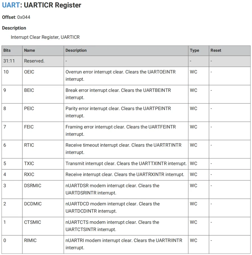 |
UARTRXINTR | The receive-full interrupt changes state when one of the following events occurs:
| The interrupt is cleared in both cases via the following methods:
|
UARTTXINTR | The send interrupt changes state when one of the following events occurs:
It should be noted that the UARTTXINTR interrupt of the transmit-side FIFO mentioned above will not be triggered during the initialization of the serial port and interrupt, and will only be set after the written data leaves one unit buffer position of the transmit FIFO. | The interrupt is cleared in both cases via the following methods:
It should be noted that to update the transmit-side FIFO memory, data needs to be written into the transmit-side FIFO either before enabling the UART and interrupts or after enabling the UART and interrupts. |
UARTRTINTR | When the receiver FIFO is not empty and no additional data is received within a 32-bit cycle, a receive timeout interrupt will be generated. | The interrupt is cleared in both cases via the following methods:
|
UARTEINTR | When an error occurs while the UART is receiving data, an error interrupt will be generated. The errors include: frame error, parity error, overflow error, and Break error. We can determine which interrupt has occurred by reading the raw interrupt status register UARTRIS or the masked interrupt status register UARTMIS. | Clear the relevant bits by writing to the interrupt clear register UARTRIS (bits 7 to 10 are error clear bits) |
1.2.7.2 Enabling and Disabling UART Interrupts
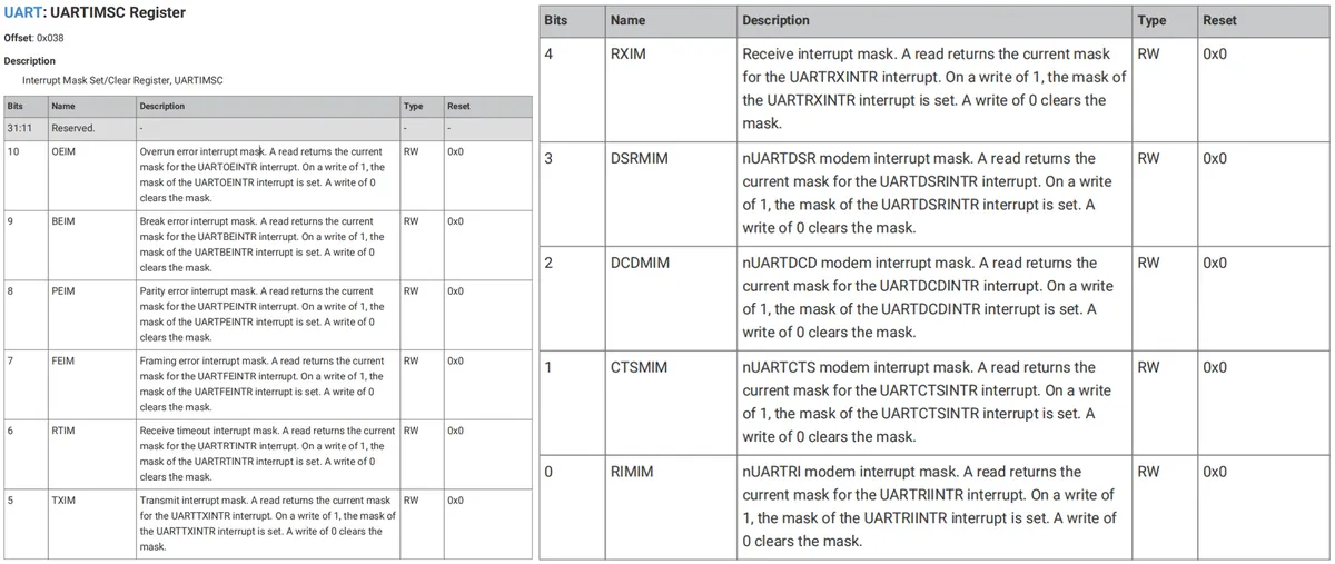
An interrupt event can trigger a controller-level interrupt, and we can enable or disable individual interrupts by setting or clearing the corresponding bits in the UARTIMSC (Interrupt Mask Set/Clear Register):
1.2.7.3 Reading of UART Interrupt Status
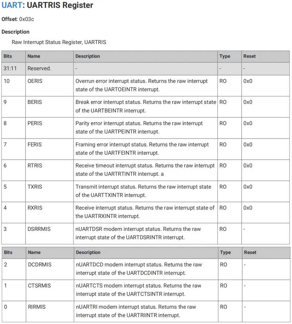
If interrupts are masked, the raw interrupt status of the source can always be viewed via the UART Raw Interrupt Status (UARTRIS) register:
Original Interrupt and Masked Interrupt
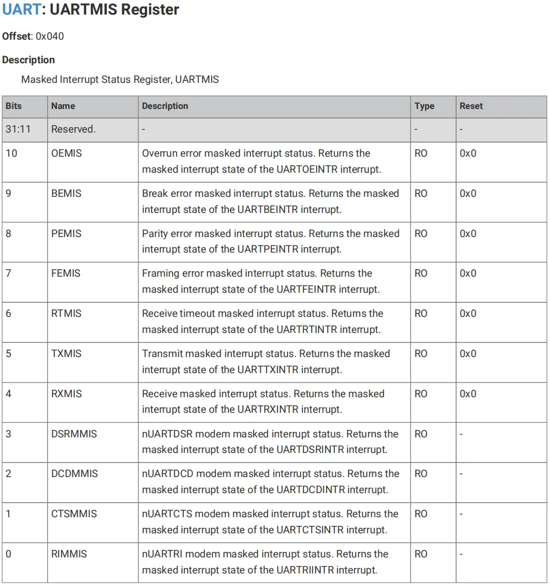
The status of each interrupt source can be read either from the raw interrupt status register UARTRIS or from the masked interrupt status register UARTMIS:
- Raw interrupt refers to the status of an external interrupt source. Regardless of whether the chip masks this interrupt source, the interrupt status of this interrupt source will be stored in a register, so that it can be read through the corresponding function.
- Maskable Interrupt refers to the status of an interrupt source after an interrupt mask mask is set
There are 11 maskable interrupts in the UART, all of which are ORed and then connected to UARTINTR, which is further connected to the system interrupt controller. The UART can only generate a single interrupt request to the controller at any given time, while software can read the UART Masked Interrupt Status (UARTMIS) register to service multiple interrupt events within a single interrupt service routine:
1.2.7.4 Interrupt Operation of FIFO
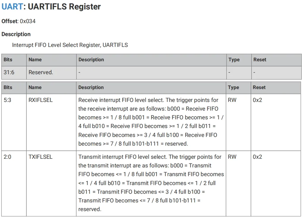
The FIFO depth at which an interrupt is generated can be controlled via the UART Interrupt FIFO Level Select (UARTIFLS) register, and the two FIFOs can be configured independently to trigger interrupts at different levels:
1.3 Overview of UART on Raspberry Pi Pico
The Raspberry Pi Pico has two serial port peripherals: UART0 and UART1. Both have identical parameters, and each serial port supports the following functions:
- Independent 32×8 Tx transmit FIFO memory and 32×12 Rx receive FIFO memory
- Programmable baud rate generator generated by the clk_peri clock
- Standard asynchronous communication bits (start bit, stop bit, parity bit) that are added during transmission and removed upon reception
- Wire break detection
- The valid data bits can be selected as 5,6, 7 or 8 bits, and the stop bits can be selected as 1 or 2 bits.
- programmable hardware flow control function
The port multiplexing table of GPIO is as follows:
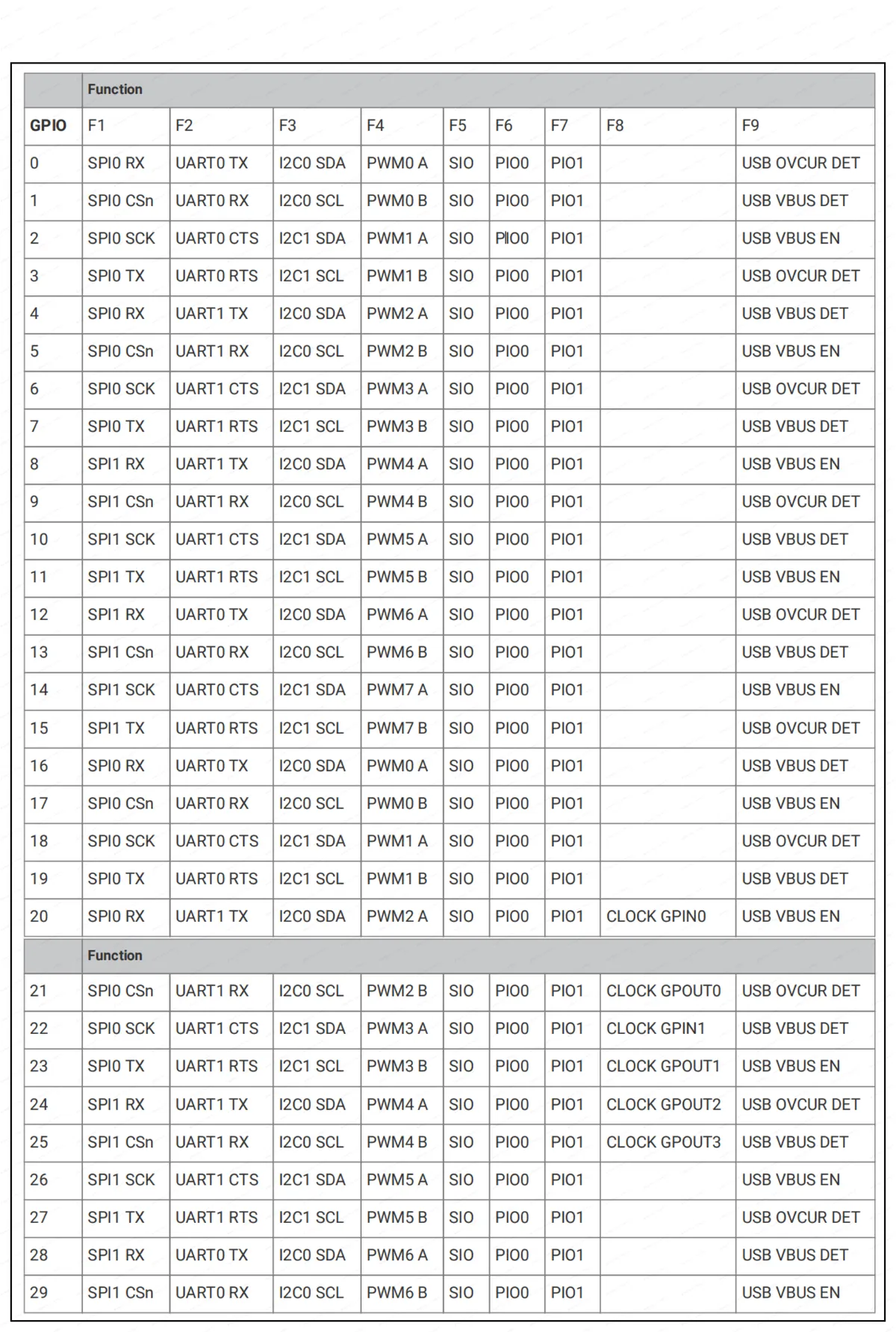
You can also directly check the pinout diagram of the Raspberry Pi Pico:
- UART0 can be mapped to GPIO 0/1, GPIO 16/17, and GPIO 21/22
- UART1 can be mapped to GPIO 6/7, GPIO 11/12
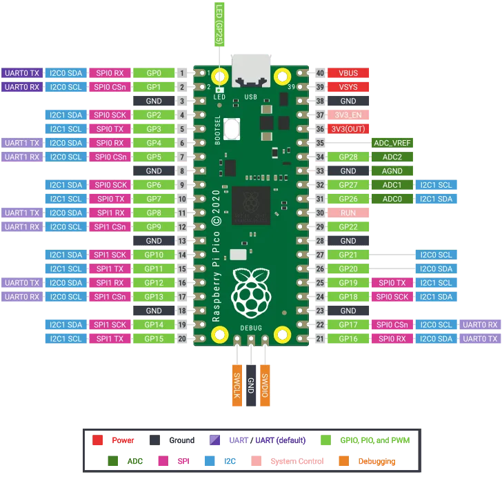
port multiplexing
A microcontroller integrates numerous built-in peripherals, and the external pins of these peripherals are all multiplexed with GPIO pins. In other words, a GPIO pin is considered to support multiplexing if it can function both as a general-purpose input/output communication pin and as a communication pin for these internal peripherals.
UART has the following functional pins:
- TX Port - UARTnTXD: Used for serial data transmission
- RX Terminal - UARTnRXD: Used for receiving serial port data
- RTS terminal - nUARTRTS: UART output flow control
- CTS Pin - nUARTCTS: Input UART Flow Control
The clock of the serial peripheral, UARTCLK, is driven by the peripheral clock clk_peri, and the clock of the low-speed APB bus, PCLK, is driven by the system clock clk_sys:
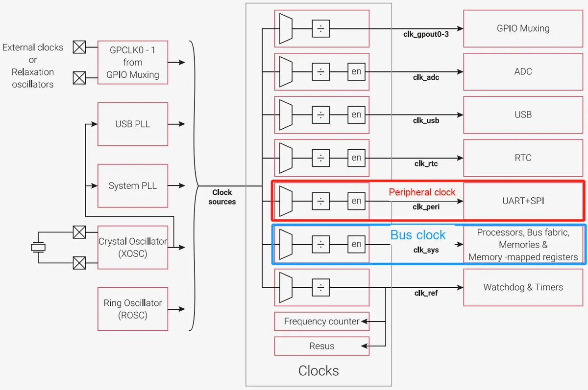
The baud rate for serial communication of the Raspberry Pi Pico can be adjusted within the range from 300 bps to 1 Mbps.
2. Software Control Method
2.1 Constructor and Initialization Method of the machine.UART Class
The constructor of the machine.UART class is as follows:
class machine.UART(id, ...)
Construct a UART object with the given id
The parameters are defined as follows:
- id - specifies the ID number for constructing the UART object,
The Raspberry Pi Pico has two serial port peripherals: UART0 and UART1, so the ID number can be set to 0 or 1.
It is recommended here that only the ID number be passed when constructing the UART object, and other parameters (such as baud rate, valid data bits, etc.) be set in the initialization method.
Additional Reminder
In the previous section, we mentioned that the constructors of the subclasses under the built-in machine module in MicroPython do not support keyword arguments. If you want to use keyword arguments to initialize these subclasses, you can simply declare the peripheral object to be constructed in the constructor, and then use keyword arguments to initialize the peripheral in the init () method.It should be noted that the initialization methods of the subclasses built into the machine module in MicroPython do not perform range checking on the parameters passed into them (for example, for the initialization function of the machine.UART class, we can pass 100 to the bits parameter, and no error prompt will be given at this time), which requires us to pay special attention to the range of the parameters passed into them.
The initialization method of the machine.UART class is as follows:
UART.init(baudrate=9600, bits=8, parity=None, stop=1, *, ...)
Initialize the UART bus with the given parameters
The parameters are defined as follows:
- baudrate - Baud rate
- bits - valid data bits, which can be set to 5,6, 7 or 8
- parity - parity bit, options available:
- None - No Parity
- 0 - Even Parity
- 1 - Odd Parity
- stop - the number of stop bits, either 1 or 2
Other keyword arguments that the port may support include:
- tx - TX pin to be used
- rx - the RX pin to be used
- txbuf - Character length of the TX buffer
- rxbuf - Character length of the RX buffer
- timeout - the time to wait for the first character, in milliseconds
- timeout_char - the waiting time between characters, in milliseconds
- invert - Data line to be inverted
- 0 - No line inversion (both lines are in logic high level in idle state)
- UART.INV_TX - Invert the TX line (the idle state of the TX line will now be logic low)
- UART.INV_RX - Invert the RX line (the idle state of the RX line will now be logic low)
- UART.INV_TX | UART.INV_RX - The two lines will be inverted (idle state at logic low level)
- flow - specifies the hardware flow control signal to be used; this value is a bitmask
- 0 - Hardware flow control signals will be ignored
- UART.RTS - Enables receive flow control, which will signal via the RTS output pin to indicate whether the receive FIFO has sufficient space to accept more data.
- UART.CTS - When the CTS input pin signals that the receiver buffer has insufficient space, transmission flow control will be enabled by pausing transmission; UART.RTS | UART.CTS - Both will be enabled to achieve full hardware flow control
You can call init () on the same object multiple times to dynamically reconfigure the UART. This feature enables an MCU chip with only one UART peripheral to implement time-division multiplexing of the serial port peripheral by configuring connections to different pins through multiple initialization methods. It should be noted that the UART peripheral can only use the two currently specified pins for data transmission and reception at the same time; meanwhile, do not call deinit (), as it will prevent subsequent calls to init ().
2.2 Other methods of the machine.UART class
Method | Description |
UART.deinit() | Shut down the UART bus. After calling this method, you will not be able to call init () on the object, and a new UART instance needs to be created. |
UART.any() | Returns an integer representing the number of characters that can be read without blocking:
|
UART.read([nbytes]) | Read character:
The return value is a bytes object of the bytes read, and None is returned after a timeout. |
UART.readinto(buf[, nbytes]) | Read bytes into buf. :
The return value is the number of bytes read and stored in buf, and None is returned after a timeout. Using this method to store the read bytes in a pre-allocated buffer can avoid creating unnecessary objects and reduce memory fragmentation. |
UART.readline() | Reads a line ending with a newline character. If a timeout is defined in the initialization method, this method returns after the specified line of data is read or when the timeout duration elapses. The return value is a line of data that has been read, and None will be returned after a timeout. |
UART.write(buf) | Writes the byte buffer to the bus. The return value is the number of bytes written; if a timeout is defined in the initialization method, None will be returned after the timeout expires. |
UART.sendbreak() | Send an interrupt signal on the bus, which will cause the bus driver to go low for a longer duration than that required for a normal character transmission. |
UART.flush() | Wait until all data has been sent. If a timeout occurs, an exception will be thrown. The duration of the timeout depends on the size of the transmission buffer and the baud rate. Unless serial port flow control is used, a timeout should not occur. For the RP2040 chip used in the Raspberry Pi Pico, calling this method will return after the last byte is sent. Meanwhile, we can add a one-character waiting time when calling this method. |
UART.txdone() | Notify whether all data has been sent or no data transmission has occurred:
For the RP2040 chip used in the Raspberry Pi Pico, when this method is called, it may return True even while the last byte of the transmission is still being sent. Meanwhile, we can add a one-character wait time when invoking this method. |
UART.irq (trigger, priority=1, handler=None, wake=machine.IDLE) | Function for setting serial port interrupt:
It should be noted that the callback function will be invoked as long as either of the following two conditions is met:
This means that when the processing function is called, there will be 1 to 8 characters waiting. |
Here, UART.irq is unavailable on the Raspberry Pi Pico microcontroller in MicroPython v1.23.0, but this does not mean that we can only use the blocking method to polling to detect whether there is data available to receive in the serial port (i. e., repeatedly execute the UART.any () method and judge based on its return value); instead, we can use coroutines to implement non-blocking serial port reading.
Blocking Work and Non-blocking Work
The so-called blocking mode means that when the "condition for successful execution" of a certain function cannot be met currently, this function will block the currently executing thread, and the program execution flow will resume and continue to execute after the timeout period arrives or the "condition for successful execution" is met. In contrast, the non-blocking mode is just the opposite: even if the "condition for successful execution" of a certain function cannot be met currently, this function will not block the currently executing thread but return immediately to keep the program execution flow running continuously.
Simply put, using a blocking function means that when executing this function, we have to wait until the function finishes running / a certain event occurs; if the event does not happen, the process or thread will be blocked and the function cannot return immediately. In contrast, the non-blocking mode means that when a process or thread executes this function, it does not have to wait for the event to occur — it will definitely return once executed, and reflect the execution status of the function through different return values.
Polling and Interrupts
Polling refers to the method in which the CPU continuously queries the status of a certain external device; if the external device is ready, the CPU can send data to it or read data from it. Since this method requires the CPU to constantly query the bus, the execution of instructions is affected, resulting in very low efficiency; by contrast, the interrupt mode overcomes the shortcomings of the CPU polling external devices. Under normal circumstances, the CPU executes instructions and does not actively check the status of external devices. After an external device is ready, it sends an interrupt signal to the CPU. After receiving the interrupt signal, the CPU stops its current work and processes the corresponding device according to the device number specified by the interrupt signal.This processing method neither affects the operation of the CPU nor ensures that the data of external devices can be processed in a timely manner, resulting in high work efficiency.
2.3 select module
Consider the following scenario: we are developing a wireless motion sensor that can detect motion data, as well as temperature and humidity data, and transmit the data to a mobile phone via Bluetooth. On the Raspberry Pi Pico, one UART is connected to a gyroscope sensor, and the other UART is connected to a temperature and humidity sensor.
At this point, the gyroscope sensor and the temperature and humidity sensor will periodically transmit data to the Raspberry Pi Pico. We need to read the data when it is available, and perform other operations (such as sending the received sensor data to the Bluetooth chip) when there is no data to read. To implement this function, we can continuously use the two UART.any () methods in a while loop for judgment: start receiving data when there is receivable data on any of the serial ports, and perform other operations only after the data is received.At this point, the program is essentially stuck waiting to receive serial port data; if no data is received for a long time (for example, the external temperature and humidity sensor is damaged due to a hardware circuit fault and thus cannot send data), the program will be blocked.This problem can be solved by using multithreading to run data receiving tasks, data sending tasks and other tasks, adopting coroutines, and using timers to start multiple scheduled execution tasks. However, using the select module to monitor the status changes of the serial port and perform corresponding operations when there is data available for reception is undoubtedly the most concise method. The select module provides an effective way to simultaneously monitor the status of multiple IO objects and carry out corresponding processing when there is data readable or writable.
Meanwhile, let's imagine a more complex scenario: this device also requires using sockets for network communication to complete data transmission and reception. In this case, implementing the monitoring of the two serial ports and the socket port with other methods would be extremely cumbersome and inelegant.
The select module is a module in Python's standard library that provides basic functionality for I/O multiplexing. In Python, I/O multiplexing refers to the ability to simultaneously monitor state changes (such as readability, writability, etc.) of multiple file descriptors (e. g., sockets), and perform corresponding operations whenever any one of the file descriptors is ready. This technique can significantly improve the performance and efficiency of a program when handling a large number of concurrent connections.Using the select module can avoid the overhead of threads or processes, as it can handle multiple I/O events within a single thread. This is extremely important for high-concurrency network servers, since creating and destroying threads or processes consumes a large amount of resources.
In MicroPython, the select module provides the following methods:
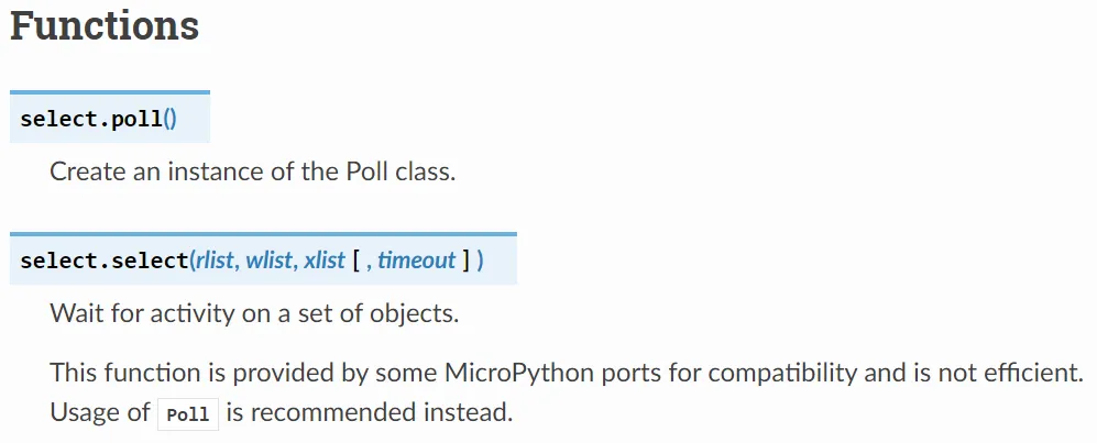
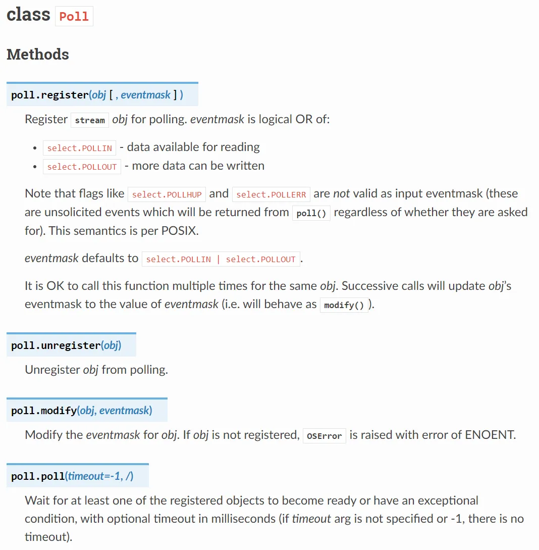
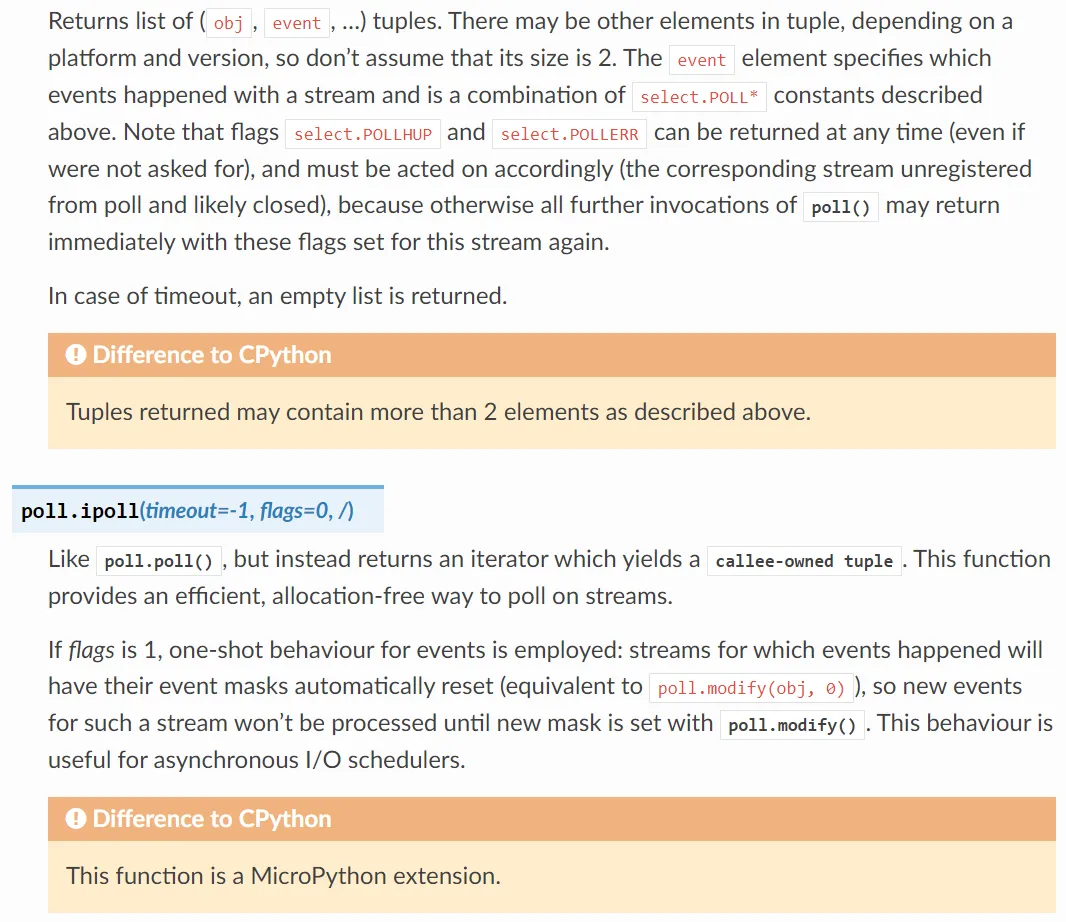
Simply put, we first need to call select.poll () to create an instance of the Poll class, which is a polling object used to monitor devices that read and write data in ByteFlow mode, and then use the Poll.register method to register the devices to be monitored with this polling object. After that, we use the Poll.poll method to listen for events; this method will block and wait until one or more devices are ready for I/O operations (such as reading or writing). When an event occurs, the Poll.poll method will return a list containing event objects.Each event object has an `fd` attribute that indicates the device where the event occurs, and an `events` attribute that specifies the event type of the device. We can determine the event type and the corresponding device by reading the `fd` and `events` attributes, then perform the matching operations accordingly.
2.4 Introduction to CH340 Chip Driver
When communicating using the serial port module of a computer and a microcontroller, we need to use a USB-to-TTL chip to convert USB protocol signals into serial Communication Protocol (TTL level). Our development board adopts the CH340K chip to realize level conversion. The CH340K is a USB-to-serial port (TTL) chip launched by Nanjing Qinheng Microelectronics Co. , Ltd. , which integrates an internal crystal oscillator circuit and requires no external crystal oscillator or capacitors, greatly reducing the complexity of peripheral circuits. Meanwhile, it supports multiple baud rates ranging from 300bps to 2Mbps, making it suitable for a variety of communication rate requirements.
The circuit of USB to TTL level is shown in the following figure:
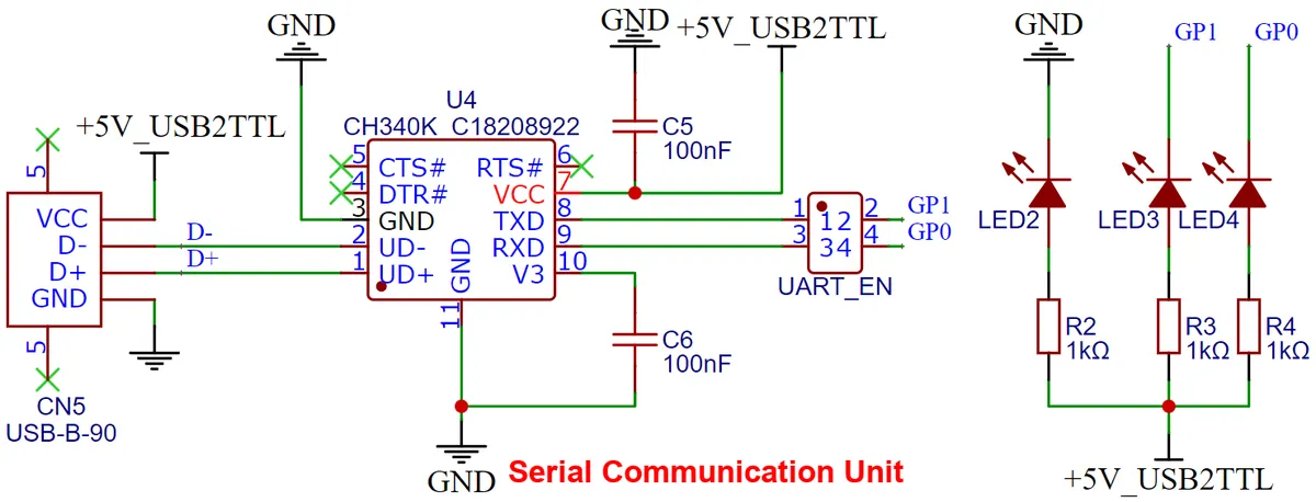
As a USB peripheral chip, the CH340K requires recognition and support from the operating system to function properly. We must first install the CH340K chip driver to enable normal serial communication via the CH340K. This driver acts as a bridge between the USB protocol and the serial port protocol, allowing applications to communicate with the CH340K chip through standard serial port interfaces (COM ports).
Here, the driver for the CH340K chip can be downloaded from the following address:
CH341SER.EXE - Nanjing Qinheng Microelectronics Co., Ltd.
You can also find it in our folder elegance-devkit v1\Development Software\CH340 Driver:

2.5 Introduction to XCOM Software
XCOM is a data transmission and debugging tool used in embedded system development, which is typically applied for serial communication between embedded devices and computers. It can display the transmitted and received data of serial communication in real time, supports the configuration of common baud rates, data bits, stop bits and parity bits, and is capable of saving communication data as log files.
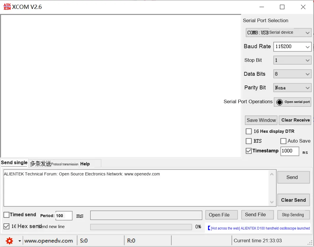
The download link for the ALIENTEK XCOM software is as follows:
You can also find it in our folder elegance-devkit v1\Development Software\XCOM Software:

For detailed usage instructions, please refer to the following article: http://47.111.11.73/docs/tool/ruanjian/ATK-XCOM.html
2.6 SerialPlot Debugging Software
SerialPlot is a debugging tool for plotting serial port data in real time, which is ideal for monitoring the real-time data transmitted via serial port by embedded devices or microcontrollers. It can plot the numerical data received from the serial port into charts, making the debugging process more intuitive.
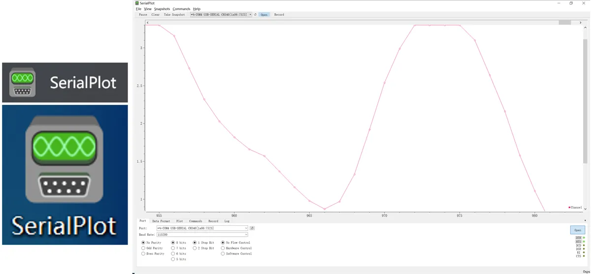
Its basic functions include:
- Real-time Plotting: SerialPlot can receive serial port data in real time and plot it into a curve graph
- Data Saving: The received data can be saved as a CSV file to facilitate subsequent analysis.
- Multi-channel support: capable of parsing multiple data formats including ASCII and binary formats, and supporting the simultaneous plotting of data from multiple channels
For download and installation, you can refer to the link:
The software can also be found in our folder elegance-devkit v1\Development Software\SerialPlot:

For instructions on usage, please refer to:
Real-Time Waveform Display: Using the Serial-to-Waveform Software SerialPlot - CSDN Blog
3. Application Examples
3.1 Simple Serial Data Transmission and Reception
In the following experiment, we need to use a MiniUSB data cable to connect the Fengya No. 1 Board - Universal Compatible Expansion Board 's UART0 USB port to the USB port on a computer:
In the following code, we have designed a program for implementing serial port (UART) data transmission and reception.
Sample code is as follows, which is located in the folder of the supporting materials: elegance-devkit v1\Demo\07 UART_ReadWrite:
# Python env   : MicroPython v1.23.0
# -*- coding: utf-8 -*-
# @Time    : 2024/6/23 9:16 PM
# @Author  : Li Qingshui
# @File    : main.py
# @Description : UART experiment, implementing simple serial data sending and receiving

# ======================================== Import Modules =========================================

# Hardware-related modules
from machine import UART, Pin
# Time-related modules
import time

# ======================================== Global Variables ============================================

# Serial receive count variable
recv_count: int = 0

# ======================================== Functions ============================================

def LED_Blink(led_obj: Pin, delay_time: int) -> None:
    """
    Control the LED blinking.

    Performs subsystem blinking control of the LED to indicate that the program has stopped running.

    Args:
        led_obj (Pin): LED object, the GPIO controller used to control the LED
        delay_time (int): Delay time in milliseconds

    Returns:
        None
    """
    while True:
        # Turn on the LED
        led_obj.on()
        # Delay for delay_time ms
        time.sleep_ms(delay_time)
        # Turn off the LED
        led_obj.off()
        # Delay again for delay_time ms
        time.sleep_ms(delay_time)

# ======================================== Custom Classes ============================================

# ======================================== Initialization ==========================================

# Power-on delay of 3 s
time.sleep(3)
# Print debug information
print("FreakStudio : UART Read and Write Experiment")

# Create the serial port object, set the baud rate to 115200
uart: UART = UART(0, 115200)
# Initialize the uart object with a baud rate of 115200, 8 data bits, no parity bit, and 1 stop bit
# Set the serial port timeout to 100ms
uart.init(baudrate  = 115200,
          bits      = 8,
          parity    = None,
          stop      = 1,
          tx        = 0,
          rx        = 1,
          timeout   = 100)

# Set GPIO 25 as the LED output pin, pull-down resistor enabled
LED: Pin = Pin(25, Pin.OUT, Pin.PULL_DOWN)

# ========================================  Main Program  ===========================================

# Run in a loop
while True:

    # Print debug information, outputting the serial send/receive counts
    print("UART0 RECV COUNT: ", recv_count)
    # Delay 100ms
    time.sleep_ms(100)

    # Check whether the serial receive count variable is greater than or equal to 10
    if recv_count >= 10:
        # Reset the serial receive count variable to zero
        recv_count = 0
        break

    # Send data to the serial port
    uart.write("Hello, UART!")
    # Send debug information
    print("UART0 SEND DATA")

    # Check whether there is data to read
    if uart.any():
        # Print the number of readable characters
        print("number of characters that can be read:", uart.any())
        # Turn on the LED as an indicator
        LED.on()
        # Read one line of data
        data = uart.readline()
        # The received data is b'Hello, UART!\r\n'; the string is of type bytes
        print("UART0 RECV DATA: ", data)
        # Decode the received data
        print("DECODE UART0 RECV DATA: ", data.decode('utf-8'))
        # Delay 300 ms
        time.sleep_ms(300)
        # Turn off the LED
        LED.off()
        # Delay 300 ms
        time.sleep_ms(300)
        # Increment the UART receive counter variable
        recv_count = recv_count + 1

# After 10 transmissions and receptions, exit the loop and blink the LED
print("Stop Program Running")
LED_Blink(LED, 100)
In the above code, we have performed the following operations:
- Initialization configuration: Configure UART0 serial port, set the baud rate to 115200, configure GPIO0 as TX (transmit), GPIO1 as RX (receive), set the timeout period to 100ms, and configure GPIO25 pin as the LED control pin
- Use
whileloop to implement serial port data transmission and reception: send the stringHello, UART!each time and try to read data, decode and print the received data, and control the LED to turn on and off to indicate the receiving operation at the same time - When the number of data receptions reaches 10, break out of the loop and call the
LED_Blinkfunction to make the LED blink continuously
Here, the data received via the serial port is of the bytes type (an immutable binary byte sequence). As an immutable data type, bytes is used to represent byte sequences, stores data in units of bytes, and has a value range of 0 to 255. The bytes type is similar to the string type (str), except that its character encoding is bytes (the raw binary data representation) rather than Unicode characters. The bytes type is extremely useful in scenarios that require binary data processing, such as network communication, file reading and writing, encryption and decryption.In Python, prefixing a string with b denotes the bytes type.
In the above program, we use the following code to decode the received immutable binary byte sequence and convert it into a string type:
# Decode the received data
print("DECODE UART0 RECV DATA: ", data.decode('utf-8'))
Launch the XCOM software and select the COM port corresponding to the CH340K chip:
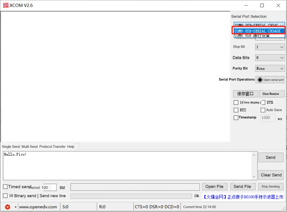
The serial communication parameters are consistent with those in the program:
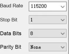
All other sending and receiving parameters can be left as default.
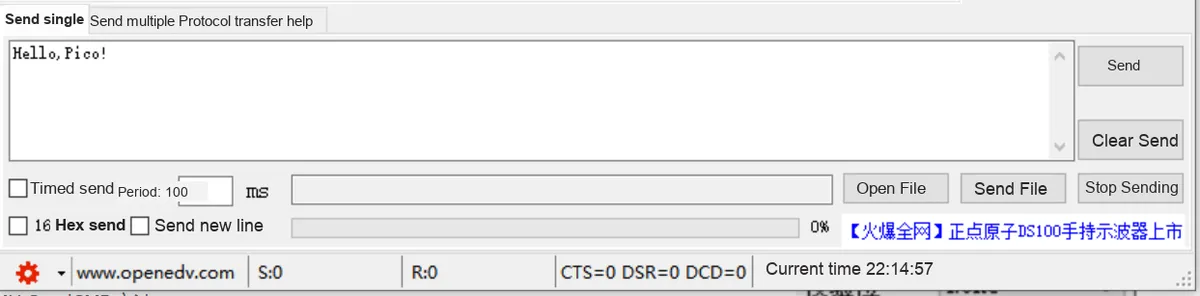
Click to open the serial port:
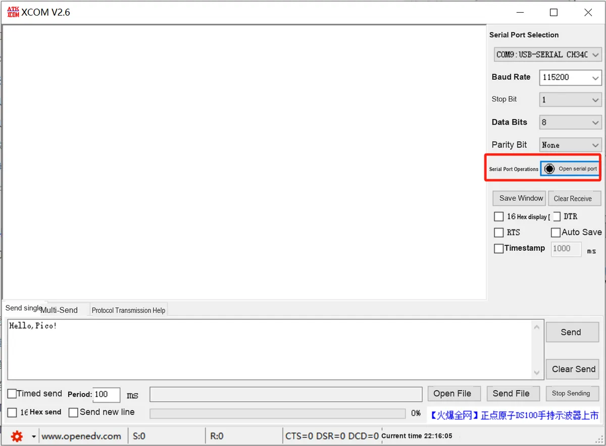
Burn the program, open the terminal, and the following content will be displayed:
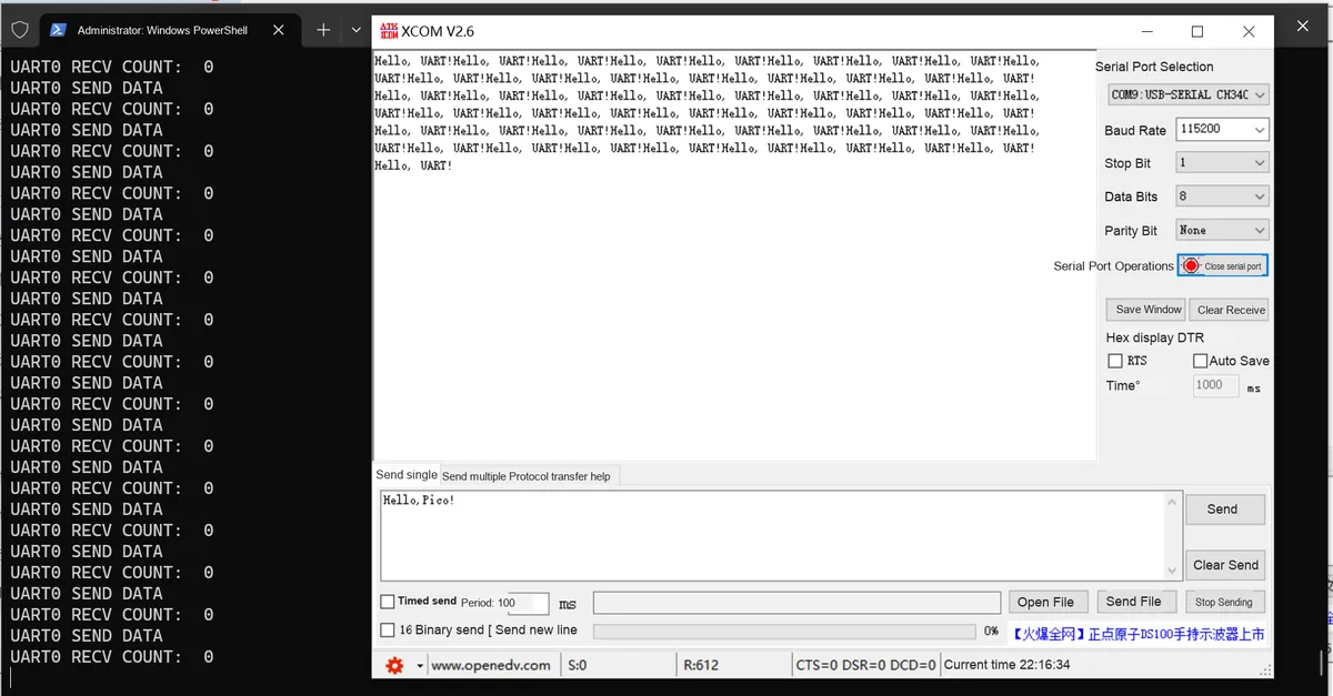
It can be seen that when we do not perform any operation, XCOM software can normally receive the data sent by the Raspberry Pi Pico.
We try to send a string from the computer via the XCOM software Hello, Pico! to the Raspberry Pi Pico:
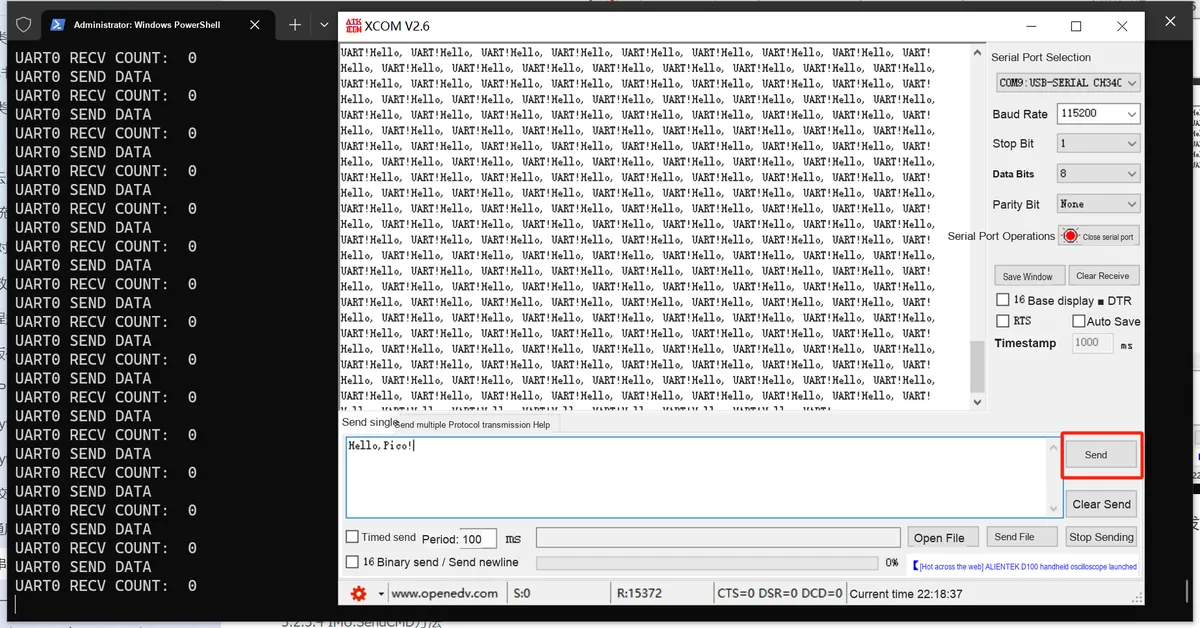
You can see that the terminal outputs the number of characters received via the serial port of the Raspberry Pi Pico, as well as the data before and after decoding:
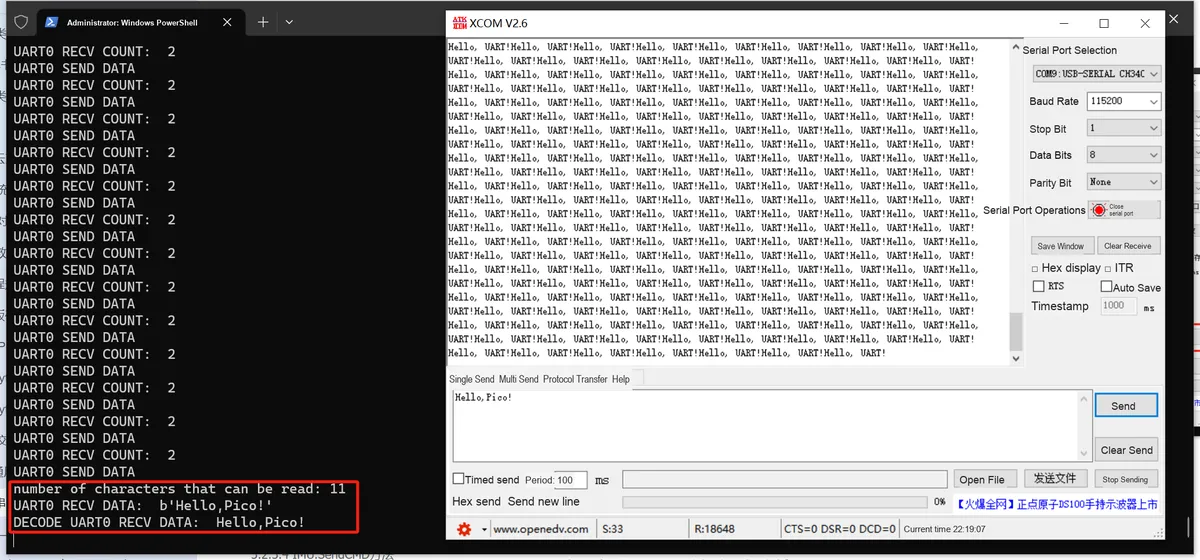
At the same time, each time a string is sent from the computer via the XCOM software, the on-board Pico of the Raspberry Pi LED will blink once. After ten consecutive transmissions, the Raspberry Pi Pico stops receiving serial port data, and the on-board LED keeps blinking:
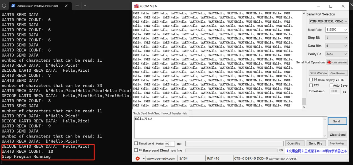
Additionally, when the Raspberry Pi Pico transmits and receives data via the serial port, the Fengya No. 1 Board - Universal Compatible Expansion Board 's serial port transmit-receive indicator LED3 will light up intermittently:
3.1 Application Experiment.mp4 76.0 MB
3.2 Serial Port Parsing of JY61 Gyroscope Protocol Frame
3.2.1 Introduction to JY61 6-axis Gyroscope
JY61 is a high-performance 3D motion attitude measurement system based on MEMS technology. It integrates a three-axis gyroscope and a three-axis accelerometer. Compared with the MPU6050 six-axis gyroscope module, JY61 performs quaternion calculation and Kalman filtering via its built-in microcontroller, supports communication in both UART and I2C modes, adopts custom protocol frames during communication, and supports operations such as angle zeroing, calibration and sleep of the sensor by sending command packets through the serial port.
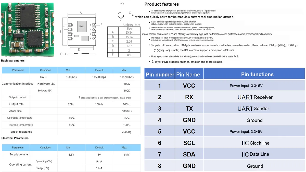
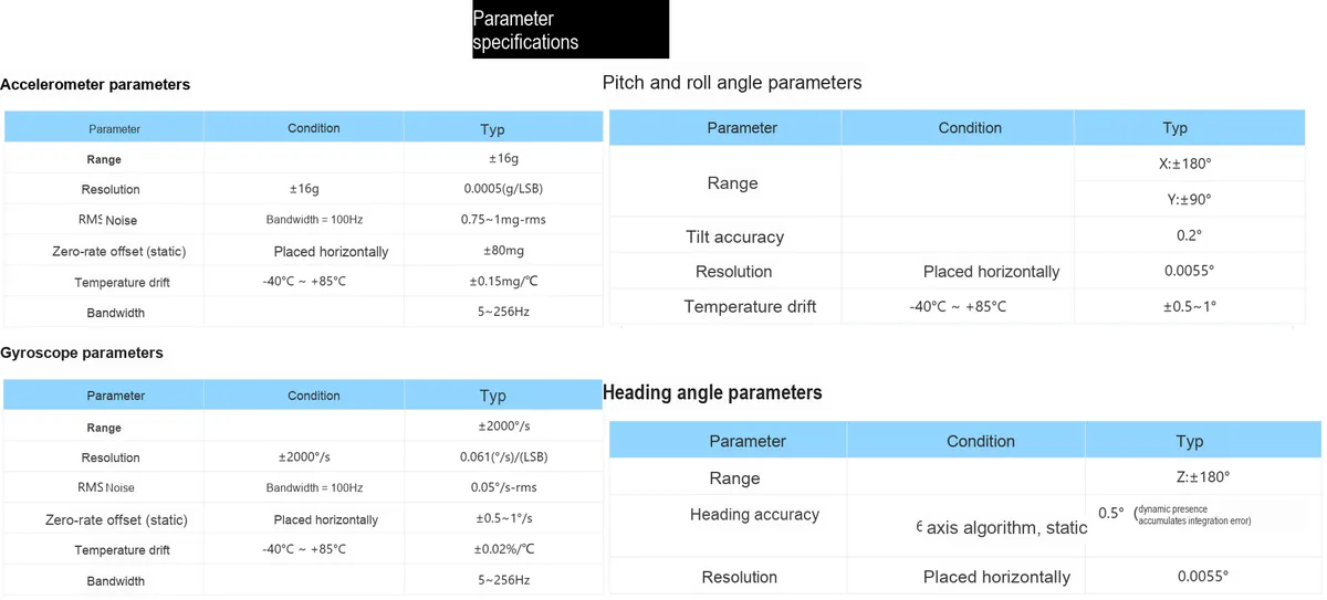
3.2.2 Introduction to JY61 Serial Port Protocol
3.2.2.1 Data Reading
The JY61 starts operating immediately after power-on, and cyclically transmits 1 frame of data (which contains 11 data packets) via the serial port. The format of the data frame is as follows:
Protocol Header | Data Type | Data 0 lower 8 bits | Data 0 upper 8 bits | Data 1 lower 8 bits | Data 1 upper 8 bits | Data 2 lower 8 bits | Data 2 upper 8 bits | Data 3 lower 8 bits | Data 3 upper 8 bits | checksum |
HEADER 0x55 | TYPE[1] | DATA0L [7:0] | DATA0H [15:8] | DATA1L [7:0] | DATA1H [15:8] | DATA2L [7:0] | DATA2H [15:8] | DATA3L [7:0] | DATA3H [15:8] | SUMCRC[2] |
The parameters are defined as follows:
- Header HEADER - Value is 0x55, used for data synchronization
- Data Type Type - Indicates the data type, there are three types in total: 0x51,0x52 and 0x53
- 0x51 - Indicates that acceleration data is to be sent
- 0x52 - Indicates that angular velocity data is sent
- 0x53 - indicates that angle data is to be transmitted
- Data bit DATA - It is transmitted in two parts: the upper 8 bits DATAxH and the lower 8 bits DATAxL, where x ranges from 0 to 3, and the meaning of each data bit varies depending on the data type Type.
- When the data type is 0x51:
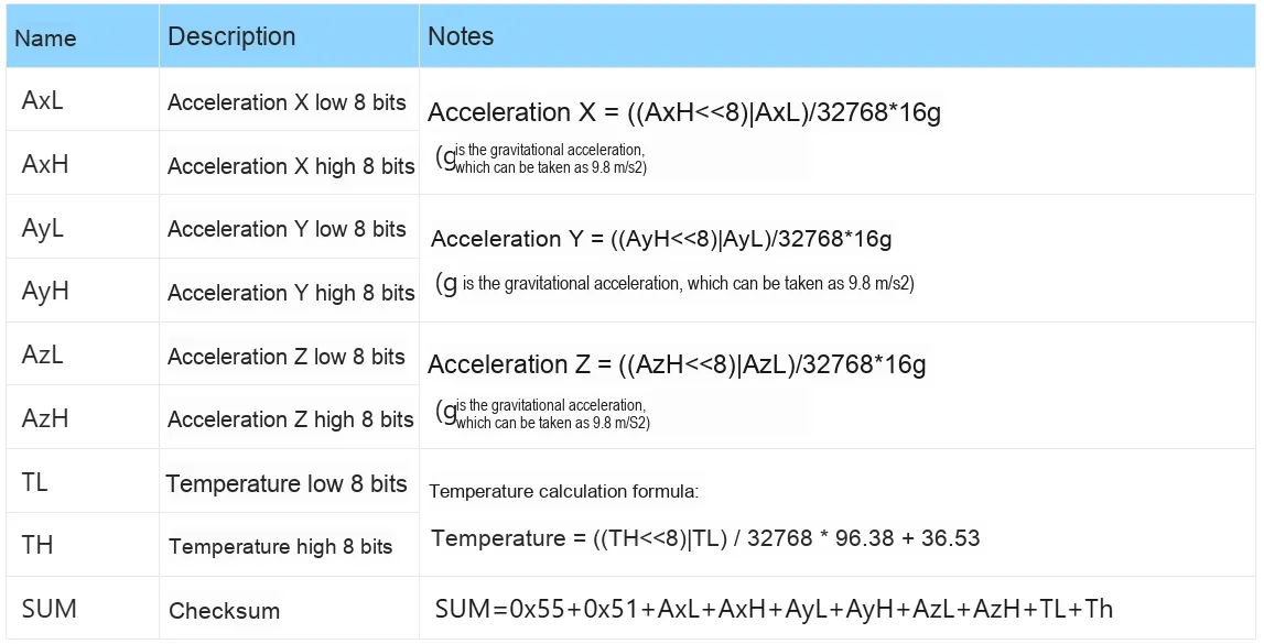
- When the data type is 0x52:
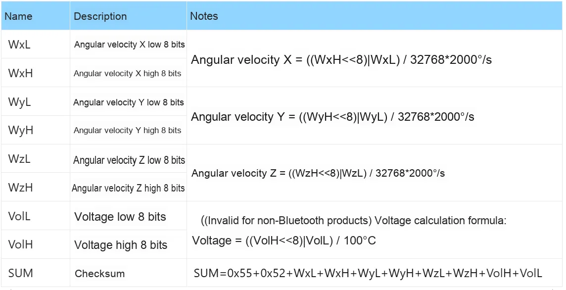
- When the data type is 0x53:
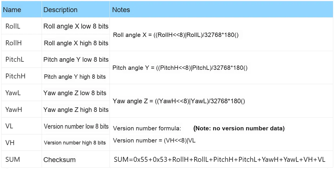
- Checksum SUMCRC -
SUMCRC=0x55+TYPE+DATA1L+DATA1H+DATA2L+DATA2H+DATA3L+DATA3H+DATA4L+DATA4H
SUMCRC is of type char, taking the lower 8 bits of the checksum
Here, it should be noted that:
- Data is transmitted in hexadecimal format.
- There are a total of 8 data bits: each data is transmitted sequentially by the low byte and the high byte, and the two are combined into a signed short-type data. For example, for the data DATA1, DATA1L is the low byte and DATA1H is the high byte. The conversion method is as follows: assuming DATA1 is the actual data, DATA1H is its high byte part and DATA1L is its low byte part, then:
DATA1=(short)((short)DATA1H<<8 | DATA1L)It must be noted here that DATA1H must first be cast to a signed short type before being shifted, and the data type of DATA1 is also a signed short type, so that negative numbers can be represented.
3.2.2.2 Command Transmission
When sending commands, please follow the protocols listed below, and note that the data shall be transmitted in hexadecimal format:
Protocol Header | Protocol Header | Command |
OxFF | 0xAA | CMD |
The following commands are available for execution:
- Z-axis angle zero reset
Note: During calibration and z-axis angle zeroing, the sensor must be kept stationary in a horizontal/vertical position!

- Accelerometer Calibration
Note: During calibration and z-axis angle zeroing, the sensor must be kept stationary in a horizontal/vertical position!

- Sleep and Wakeup
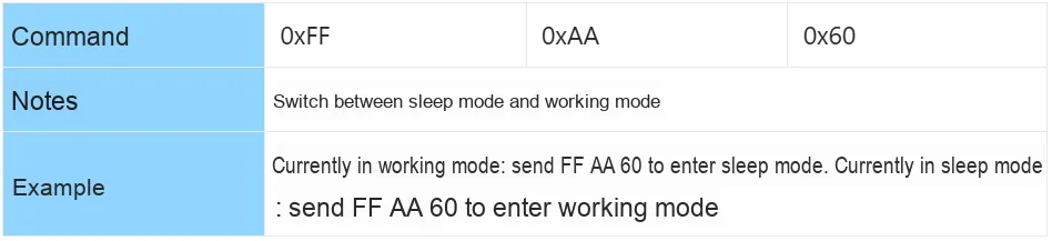
- Serial Port Transmission Mode Selection

- IIC Transmission Mode Selection

- Baud rate set to 115200

- Baud rate is set to 9600

- Bandwidth Settings
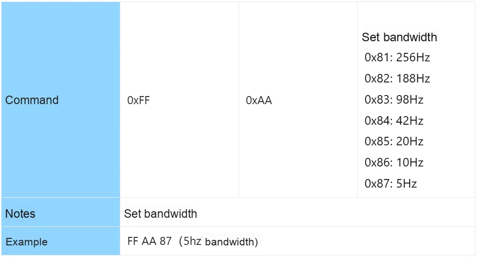
- Horizontal Installation Initialization Settings

- Vertical Installation Initialization Settings

3.2.3 Experiment on Serial Port Parsing of JY61 Data
3.2.3.1 Experimental Preparation
In the following experiment, we need to use a MiniUSB data cable to connect the Fengya No. 1 Board - Universal Compatible Expansion Board 's UART0 USB port to the USB port on a computer:
Then insert the Fengya No. 1 Board - Environment and Storage Acquisition Board into the Fengya No. 1 Board - Universal Compatible Expansion Board, and meanwhile turn on the Fengya No. 1 Board - Environment and Storage Acquisition Board 's SWITCH1 dip switch' s RXD and TXD options:
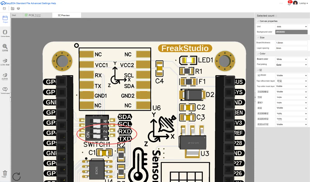
Here, the GP4 and GP5 pins of Raspberry Pi Pico UART 1 are connected to the serial gyroscope as shown in the table below:
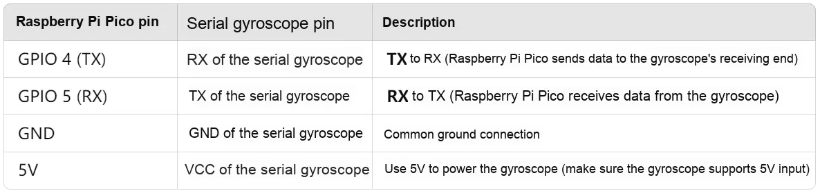
3.2.3.2 Introduction to IMU Gyroscope Code
First, we define an IMU gyroscope class that has the following methods:
Attribute/Method Name | Description |
IMU.init(UART_Obj) | Initialization method, which requires passing the serial port object that communicates with the gyroscope |
IMU.__CalChecksum() | A private method used to calculate whether the checksum is correct |
IMU.SendCMD(cmd) | used to send commands |
IMU.RecvData() | Serial port data receiving function, which receives approximately 3 frames of data within roughly the same time period at one time |
The attributes of the IMU gyroscope class are as follows:
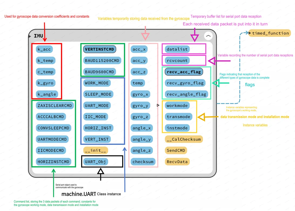
Here, we declare constants related to IMU motion data calculation — such as coefficients and constants for gyroscope data conversion, instruction lists, and operating modes (i. e., variables whose values do not need to be modified) — in the form of class variables. The code is as follows:
# Six-axis gyroscope class
class IMU:
    """
    Six-axis gyroscope class, responsible for serial communication with the IMU sensor, sending commands and receiving sensor data. The main functions of this class include device calibration, command sending, data receiving, and data parsing, and it supports multiple modes and configuration commands.

    Through this class, the user can control the gyroscope's working mode, transmission mode, and installation mode, and can receive three-axis acceleration, angular velocity (gyroscope data), and angle data (tilt angle). In addition, it provides a command-sending interface, so the user can send various control commands to configure the IMU device.

    Attributes:
        k_acc (int): Conversion coefficient for acceleration data, used to convert raw data to g units.
        k_temp (float): Conversion coefficient for temperature data, used to convert raw data to degrees Celsius.
        c_temp (float): Temperature offset constant, the offset to be added when converting temperature.
        k_gyro (int): Conversion coefficient for angular velocity data, used to convert raw data to degrees per second (°/s).
        k_angle (int): Conversion coefficient for angle data, used to convert raw data to degrees.

        ZAXISCLEARCMD (list): Command used to zero the Z-axis angle.
        ACCCALBCMD (list): Command used to perform acceleration calibration.
        CONVSLEEPCMD (list): Command used to switch the gyroscope between working mode and sleep mode.
        UARTMODECMD (list): Command used to switch to UART transmission mode.
        IICMODECMD (list): Command used to switch to IIC transmission mode.
        HORIZINSTCMD (list): Command used to set the horizontal installation mode.
        VERTINSTCMD (list): Command used to set the vertical installation mode.
        BAUD115200CMD (list): Command used to set the serial baud rate to 115200.
        BAUD9600CMD (list): Command used to set the serial baud rate to 9600.

        WORK_MODE (int): Indicates the working mode of the device (1 for working, 0 for sleeping).
        SLEEP_MODE (int): Indicates the sleep mode of the device (0 for sleeping, 1 for working).
        UART_MODE (int): UART transmission mode (1 for UART mode, 0 for IIC mode).
        IIC_MODE (int): IIC transmission mode (0 for IIC mode, 1 for UART mode).
        HORIZ_INST (int): Horizontal installation mode (1 for horizontal installation mode, 0 for vertical installation mode).
        VERT_INST (int): Vertical installation mode (0 for vertical installation mode, 1 for horizontal installation mode).

    Methods:
        __init__(self, UART_Obj: UART) -> None: Initialize the IMU class, set the UART object, and initialize related parameters.
        SendCMD(self, cmd: list[int]) -> bool: Send a command to the IMU device, used to set the device's working mode, transmission mode, etc.
        ReceiveData(self) -> tuple[float, float, float]: Receive and parse the IMU sensor data, and return the acceleration, angular velocity, and angle data.

    Example Usage:
        imu = IMU(uart_obj)
        imu.SendCMD(IMU.ACCCALBCMD)  # Send the acceleration calibration command
        data = imu.ReceiveData()     # Get the acceleration, angular velocity, and angle data
    """

    # Declare class variables: class variables are shared among all instances of the class and are used to store shared data related to the class

    # The following variables are the coefficients and constants used for gyroscope data conversion
    k_acc = 16
    k_temp = 96.38
    c_temp = 36.53
    k_gyro = 2000
    k_angle = 180

    # The following variables are the data contents of each command
    # Z-axis zeroing command
    ZAXISCLEARCMD = [0XFF, 0XAA, 0X52]
    # Acceleration calibration command
    ACCCALBCMD    = [0XFF, 0XAA, 0X67]
    # Command to switch between sleep mode and working mode
    CONVSLEEPCMD  = [0XFF, 0XAA, 0X60]
    # UART transmission mode command
    UARTMODECMD   = [0XFF, 0XAA, 0X61]
    # IIC transmission mode command
    IICMODECMD    = [0XFF, 0XAA, 0X62]
    # Horizontal installation mode command
    HORIZINSTCMD  = [0XFF, 0XAA, 0x65]
    # Vertical installation mode command
    VERTINSTCMD   = [0XFF, 0XAA, 0x66]
    # Command to set the serial baud rate to 115200
    BAUD115200CMD = [0XFF, 0XAA, 0X63]
    # Command to set the serial baud rate to 9600
    BAUD9600CMD   = [0XFF, 0XAA, 0X64]
    # The bandwidth setting commands are rarely used; leave them for the user to implement as needed
    # ============ Bandwidth protocol ============
    # | HEARDER1 | HEARDER2 |  CMD  |
    # CMD options:
    # 0x81 - Bandwidth 256 Hz
    # 0x82 - Bandwidth 188 Hz
    # 0x83 - Bandwidth 98  Hz
    # 0x84 - Bandwidth 42  Hz
    # 0x85 - Bandwidth 20  Hz
    # 0x86 - Bandwidth 10  Hz
    # 0x87 - Bandwidth 5   Hz
    # Note that after implementing the bandwidth-related commands yourself,
    # you need to add the corresponding class variables to the input parameter check of the self.SendCMD method

    # Class variables representing the working mode
    # WORK_MODE  - Working mode: 1
    # SLEEP_MODE - Sleep mode: 0
    WORK_MODE, SLEEP_MODE = (1, 0)

    # Class variables representing the data transmission mode
    # UART_MODE  - UART transmission mode: 1
    # IIC_MODE   - IIC transmission mode: 0
    UART_MODE, IIC_MODE = (1, 0)

    # Class variables representing the installation mode
    # HORIZ_INST - Horizontal installation mode: 1
    # VERT_INST  - Vertical installation mode: 0
    HORIZ_INST, VERT_INST = (1, 0)
Class Variables and Instance Variables
A class variable, also known as a Static Variable, is a variable defined inside a class but outside any method. It belongs to the class itself rather than any specific object instance. All object instances share the same class variable. Once the value of a class variable changes, this change will be reflected in all object instances.
Correspondingly, the attributes/variables defined in the init method belong to instance variables, which pertain to instances of a class (i. e., objects). Each object instance has its own independent instance variables, and the instance variables of different object instances do not interfere with each other.
Application scenarios of class variables:
- Status information of the storage class, such as counters
- Define constants for values shared by the entire class and all its object instances
- Storage class-level configuration information
Application scenarios of instance variables:
- Stores the status information of a storage object instance, such as its attributes and behaviors
- Used as a local variable in an instance method of an object
IMU The gyroscope class mainly performs the following related operations:
- Initialization:
When the __init__ method is invoked, it initializes the UART object (UART_Obj) and sets several class variables, such as operation mode, data transmission mode and installation mode. After that, it sends the Z-axis zeroing command and acceleration calibration command to ensure that the gyroscope is in the correct state.
- Send command:
The SendCMD method is used to send commands to the gyroscope. It accepts a command list as a parameter and checks whether the command is defined in the class variables. If the command is valid, it will send the command content to the serial port peripheral.
- Received data:
The RecvData method is used to receive data from the gyroscope. It runs in a loop until three frames of data (acceleration, angular velocity, and angle) are received. Each frame of data contains 11 data packets, and each data packet corresponds to a specific data type (such as acceleration, temperature, angular velocity, or angle). Once a frame of data is fully received, the method calculates the checksum and verifies whether the data is valid. If the data is valid, the method converts the data and updates the corresponding class variables.
- Data Conversion:
For the received data, this class uses several constants and coefficients for conversion. For instance, the acceleration data is divided by 32768 and then multiplied by k_acc to obtain the actual acceleration value. The temperature data is added with c_temp, divided by 32768, and then multiplied by k_temp. The angular velocity data is divided by 32768 and then multiplied by k_gyro to get the actual angular velocity value. The angle data is divided by 32768 and then multiplied by k_angle to yield the actual angle value.
- Return Data:
Once all three frames of data have been received and converted, the RecvData method returns a tuple containing acceleration, temperature, angular velocity and angle data.
3.2.3.3 Code Analysis of the IMU.__CalChecksum Method
In the IMU.__CalChecksum method for calculating the checksum, the following tasks are mainly completed: first, the method extracts the 11th byte (index 10) from the received serial port data frame, which is the checksum of the data frame; then, the method declares a variable named tempchecksum to store the temporary checksum during the calculation process, and subsequently the method iterates over the first 10 bytes (indices 0 to 9) of the data frame, adds them together, and stores the sum result back into the tempchecksum variable;Since computers use the binary system, the calculated checksum may be an integer greater than 255. To compare it with the checksum in the data frame, we need to extract the lower 8 bits of the calculated checksum, which can be achieved by performing a bitwise AND operation between tempchecksum and 0xff (i. e., 255); finally, the method compares the calculated checksum with the checksum in the data frame: if the two are equal, it indicates that the data is received correctly, and the method returns True; otherwise, it returns False.
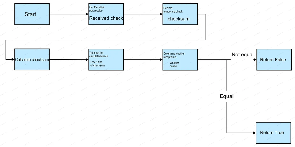
This method is usually invoked after a sequence of data is received to verify the integrity and accuracy of the data. In the IMU class, this method is used to validate whether the data frame received from the gyroscope is valid. Since this method is only to be used within the IMU class, we define it as a private method, which cannot be accessed by external code via the format: ClassName. MethodName for invocation.
The sample code is as follows:
# Private method: check whether the checksum is correct
def __CalChecksum(self) -> bool:
    """
    Calculate the checksum and determine whether it is correct.

    Returns:
        bool: Returns True if the checksum is correct, otherwise False
    """

    # Get the checksum received over the serial port
    self.checksum = self.datalist[10]

    # Declare a temporary checksum
    tempchecksum: int = 0
    # Calculate the checksum
    for i in range(0, 10):
        tempchecksum = tempchecksum + self.datalist[i]

    # Take the low 8 bits of the calculated checksum
    tempchecksum = tempchecksum & 0xff

    # Determine whether the reception is correct
    if tempchecksum != self.checksum:
        return False
    else:
        return True
3.2.3.4 IMU.SendCMD Method
In the IMU.SendCMD method for sending commands, it first checks whether the incoming command list cmd is defined in the variables of the IMU class. If the command is not defined in the variables, the method returns False; if the command is valid, the method traverses each element (i. e., each command byte) in the command list and sends them to the serial port one by one.Meanwhile, for commands that may alter the operating state of the gyroscope, we will modify the attribute in the IMU class that represents the gyroscope's operating state after sending the command: for instance, if the command is intended to switch the operating mode (switching from operating mode to sleep mode, or from sleep mode to operating mode), the method will update the self.workmode attribute according to the current operating mode.
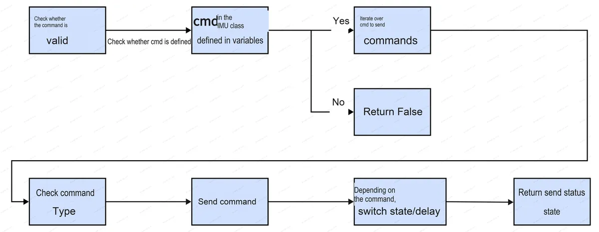
This method is usually called when specific instructions need to be sent to the gyroscope. For example, during the initialization process, it may be necessary to send a Z-axis zero-clearing instruction and an acceleration calibration instruction. In other cases, other instructions may be sent as needed to control the behavior of the gyroscope.
The sample code is as follows:
# UART command sending function
def SendCMD(self, cmd: list[int]) -> bool:
    """
    Send a command to the IMU device.

    Args:
        cmd (list[int]): List of commands to send

    Returns:
        bool: Returns True if sent successfully, otherwise False
    """

    # If the command is not defined in the IMU class variables, return False
    if (cmd != IMU.ZAXISCLEARCMD
        and cmd != IMU.ACCCALBCMD
        and cmd != IMU.CONVSLEEPCMD
        and cmd != IMU.UARTMODECMD
        and cmd != IMU.IICMODECMD
        and cmd != IMU.HORIZINSTCMD
        and cmd != IMU.VERTINSTCMD
        and cmd != IMU.BAUD115200CMD
        and cmd != IMU.BAUD9600CMD):

        return False

    # Send the command content
    for data in cmd:
        # In the UART.write(buf) method, buf must support the buffer protocol
        self.UART_Obj.write(bytes([data]))

    # If it is the command to switch between sleep mode and working mode
    if cmd == IMU.CONVSLEEPCMD:
        # Toggle and assign the workmode attribute of self
        if self.workmode == IMU.WORK_MODE:
            self.workmode = IMU.SLEEP_MODE
        else:
            self.workmode = IMU.WORK_MODE

    # If the UART transmission mode command was sent
    if cmd == IMU.UARTMODECMD:
        # The gyroscope data transmission mode is UART transmission mode
        self.transmode = IMU.UART_MODE

    # If the IIC transmission mode command was sent
    if cmd == IMU.IICMODECMD:
        # The gyroscope data transmission mode is IIC transmission mode
        self.transmode = IMU.IIC_MODE

    # If the horizontal installation mode command was sent
    if cmd == IMU.HORIZINSTCMD:
        # The gyroscope installation mode is horizontal installation mode
        self.instmode = IMU.HORIZ_INST

    # If the vertical installation mode command was sent
    if cmd == IMU.VERTINSTCMD:
        # The gyroscope installation mode is vertical installation mode
        self.instmode = IMU.VERT_INST

    # If the command to set the serial baud rate to 115200 was sent
    if cmd == IMU.BAUD115200CMD:
        # Set the serial baud rate to 115200
        self.UART_Obj.init(baudrate = 115200)

    # If the command to set the serial baud rate to 9600 was sent
    if cmd == IMU.BAUD9600CMD:
        # Set the serial baud rate to 9600
        self.UART_Obj.init(baudrate = 9600)

    # If the command is the Z-axis zeroing command or the acceleration calibration command
    if cmd == IMU.ZAXISCLEARCMD or cmd == IMU.ACCCALBCMD:
        # While the gyroscope calibration is in progress, wait 100 ms
        time.sleep_ms(500)

    return True
Here, it should be noted that the parameter passed to the UART.write () method must be a data type that supports buffer invocation and has the buffer Protocol attribute (such as strings, arrays, lists, bytes type, or mutable binary sequence bytearray, etc.). The Buffer Protocol is a data structure protocol in Python used to handle ByteFlow. It allows programmers to manipulate bytes in memory in the form of integer sequences without having to care about the underlying data representation.Data types with the buffer Protocol attribute can access individual bytes via indexing and support slicing operations, making it convenient to process ByteFlow. The buffer protocol also provides methods such as append (), extend (), pop (), etc. , for operating on sequences. Additionally, the buffer protocol supports conversion with objects of other types, for example, converting a string to a byte array, or converting a byte array to a string.The main application scenarios of buffer Protocol include network programming, file processing, serialization, etc.
In the code of the instruction sending section, we perform type conversion on the integer data to be sent in the command list:
    # Send the command content
    for data in cmd:
        # In the UART.write(buf) method, buf must support the buffer protocol
self.UART_Obj.write(bytes([data]))[]is a list comprehension in Python, used to create a new list that contains only one element, namely the variable data. Then the bytes () statement is used to convert the variable data into a byte type.
3.2.3.5 IMU.RecvData Method
In the IMU.RecvData method for data reception, first call the UART_Obj.any () method to check whether new serial port data has arrived. If new data is available, use the UART_Obj.read (1) method to receive one byte of data, then perform data conversion: convert the received byte data to its hexadecimal representation, and then convert it to a decimal integer. Next, store the converted data in the datalist list, and update the rcvcount counter according to the sequence of data packets.
Then perform data checking to verify whether the first element in the datalist is the frame header 0x55. If the frame header is detected, continue receiving data until a complete data frame (11 data packets) is received. After a frame of data is successfully received, calculate the checksum according to the data frame format, and compare it with the checksum contained in the data frame. If the checksum is correct, perform corresponding data conversion according to the type of the data frame (acceleration, angular velocity or angle).and set the corresponding reception completion flag (recv_acc_flag, recv_gyro_flag or recv_angle_flag) according to the data type.
If all types of data have been received completely, clear all flags and return the received data. If a complete data frame has not been received, or there are still data types that have not been fully received, continue to loop through the data reception, data check and data conversion operations.
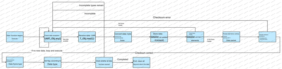
The sample code is as follows:
# UART data receiving function
# Use the @timed_function decorator to measure the running time of the IMU.RecvData method
# When there is no need to measure the running time, simply remove the @timed_function decorator
@timed_function
def RecvData(self) -> tuple[float, float, float]:
    """
    Receive and parse the IMU sensor data.

    This method receives three-axis acceleration, angular velocity, and angle data.

    Returns:
        tuple: Returns the three-axis acceleration, angular velocity, and angle data
    """
    # Loop until three frames of data (acceleration, angular velocity, angle) have been received
    while True:
        # Use the UART.any method to check whether there is data
        if self.UART_Obj.any():
            # Receive one UART byte, of type bytes
            tempdata = self.UART_Obj.read(1)
            # Convert the bytes in the data object to hexadecimal representation
            tempdata = binascii.hexlify(tempdata)
            # Convert the hexadecimal bytes object to a decimal integer
            tempdata = int(tempdata, 16)

            # Store the received data item in the datalist list
            self.datalist[self.rcvcount] = tempdata

            # If the received byte is not the frame header 0x55, start receiving again
            if self.datalist[0] != 0x55:
                # Reset the UART receive count variable to zero
                self.rcvcount = 0
            # If it is the frame header 0x55, continue receiving
            else:
                # Increment the UART receive count variable by 1
                self.rcvcount = self.rcvcount + 1

                # One frame of data consists of 11 data packets
                # If the count has not reached 11, reception is not yet complete; continue receiving the next data item
                if self.rcvcount < 11:
                    continue
                # One frame of data has been received; start parsing the data
                # ============================================ Data frame format ============================================
                # | HEADER | TYPE | DATA0L | DATA0H | DATA1L | DATA1H | DATA2L | DATA2H | DATA3L | DATA3H | SUMCRC |
                # | 0x55   | x    | x      | x      | x      | x      | x      | x      | x      | x      | x      |
                # SUMCRC=0x55+TYPE+DATA1L+DATA1H+DATA2L+DATA2H+DATA3L+DATA3H+DATA4L+DATA4H, take the low 8 bits of the checksum, of type char
                # ============================================ Data frame format ============================================
                else:
                    # If the checksum is correct, convert the data; otherwise, receive the next frame again
                    if self.__CalChecksum():

                        # If it is acceleration data
                        if self.datalist[1] == 0x51:
                            # Convert the data
                            self.acc_x = (self.datalist[3] << 8 | self.datalist[2]) / 32768 * IMU.k_acc
                            self.acc_y = (self.datalist[5] << 8 | self.datalist[4]) / 32768 * IMU.k_acc
                            self.acc_z = (self.datalist[7] << 8 | self.datalist[6]) / 32768 * IMU.k_acc
                            self.temp = (self.datalist[9] << 8 | self.datalist[8]) / 32768 * IMU.k_temp + IMU.c_temp

                            # Set the acceleration data reception complete flag
                            self.recv_acc_flag = 1

                        # If it is angular velocity data
                        if self.datalist[1] == 0x52:
                            # Convert the data
                            self.gyro_x = (self.datalist[3] << 8 | self.datalist[2]) / 32768 * IMU.k_gyro
                            self.gyro_y = (self.datalist[5] << 8 | self.datalist[4]) / 32768 * IMU.k_gyro
                            self.gyro_z = (self.datalist[7] << 8 | self.datalist[6]) / 32768 * IMU.k_gyro
                            # Set the angular velocity data reception complete flag
                            self.recv_gyro_flag = 1

                        # If it is angle data
                        if self.datalist[1] == 0x53:
                            # Convert the data
                            self.angle_x = (self.datalist[3] << 8 | self.datalist[2]) / 32768 * IMU.k_angle
                            self.angle_y = (self.datalist[5] << 8 | self.datalist[4]) / 32768 * IMU.k_angle
                            self.angle_z = (self.datalist[7] << 8 | self.datalist[6]) / 32768 * IMU.k_angle
                            # Set the angle data reception complete flag
                            self.recv_angle_flag = 1

                        # If all three frames have been received, return the gyroscope data received over a period of time
                        if self.recv_acc_flag == 1 and self.recv_gyro_flag == 1 and self.recv_angle_flag == 1:
                            # Clear the reception complete flags for the three data types
                            self.recv_acc_flag = 0
                            self.recv_gyro_flag = 0
                            self.recv_angle_flag = 0

                            # Return the gyroscope data received over a period of time
                            return self.acc_x, self.acc_y, self.acc_z, self.temp, self.gyro_x, self.gyro_y, self.gyro_z, self.angle_x, self.angle_y, self.angle_z

                    # After receiving a frame, clear the variable counting UART receptions
                    self.rcvcount = 0
Here are the following points that require detailed elaboration:
- Conversion between bytes type and int type
Here, a byte of data is received via the UART_Obj.read (1) method, and the data type is bytes:

bytes is a data type primarily used for binary data processing. It is a sequence of bytes (analogous to the string type str, which is a sequence of Unicode-encoded characters), consisting of a series of bytes, where each byte can represent an integer between 0 and 255. bytes is only responsible for storing data in the form of a byte sequence (i. e., binary form), and the representation of the data is entirely determined by the encoding method selected.
In Python, the representation of bytes defaults to displaying the corresponding ASCII characters. First, we use the hexlify () function in Python's built-in binascii module to convert the bytes in tempdata into a hexadecimal representation.
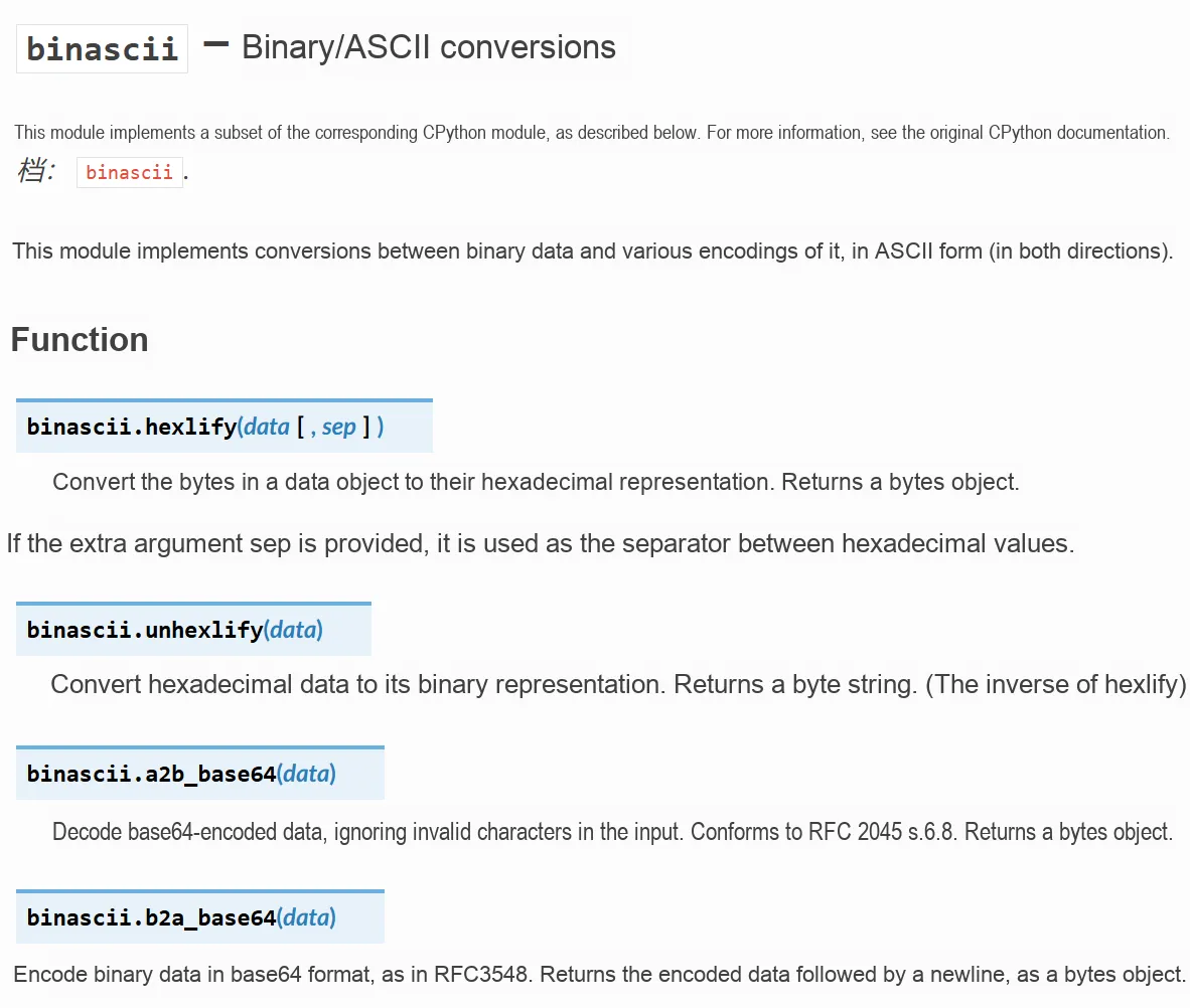
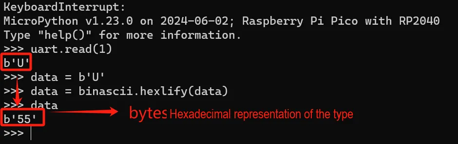
Next, we use the statement tempdata = int (tempdata, 16) to convert the hexadecimal represented string into a decimal integer, and the second parameter of this function specifies the base to be converted. This code is usually used to read binary data from the serial port and convert it into a readable format for subsequent processing and analysis.
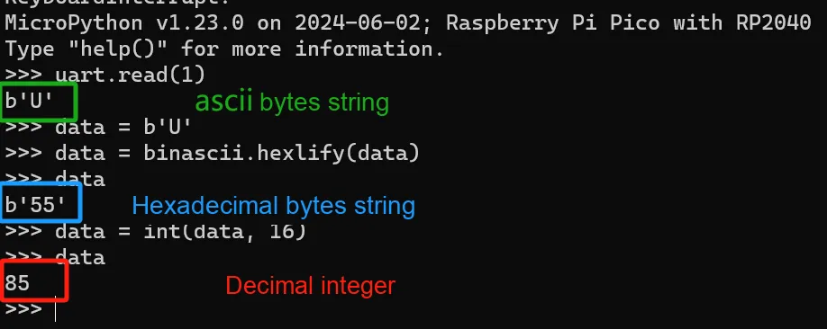
- Conversion and Bitwise Operation of Motion Data
We use the following statement to combine the lower 8 bits and upper 8 bits of the received acceleration data to generate a complete data:
self.acc_x = (self.datalist[3] << 8 | self.datalist[2]) / 32768 * IMU.k_acc
self.acc_y = (self.datalist[5] << 8 | self.datalist[4]) / 32768 * IMU.k_acc
self.acc_z = (self.datalist[7] << 8 | self.datalist[6]) / 32768 * IMU.k_acc
self.temp  = (self.datalist[9] << 8 | self.datalist[8]) / 32768 * IMU.k_temp + IMU.c_temp
Here, we primarily utilize bitwise operations. Taking the process of extracting acceleration data along the x-axis as an example, the << 8 operator performs a left bitwise shift, which is equivalent to multiplying by 256, while the | operator is a bitwise OR operation used to combine the data of two bytes. After merging the lower 8 bits and the higher 8 bits of the data, multiply the result by the conversion coefficient IMU.k_acc and then divide by 32768 to obtain the actual acceleration value. The conversion processes for other types of data follow a similar procedure.
- @timed_function decorator
When defining the data receiving method IMU.RecvData, we use the @timed_function decorator to modify it. This decorator is used to calculate the running time of the decorated function or method, and output the result to the Console.
The definition of a decorator is as follows:
# Timing decorator, used to measure function run time
def timed_function(f: callable, *args: tuple, **kwargs: dict) -> callable:
    """
    Timing decorator, used to measure and print function/method run time.

    Args:
        f (callable): The function/method to be passed in
        args (tuple): Any number of positional arguments passed to function/method f
        kwargs (dict): Any number of keyword arguments passed to function/method f

    Returns:
        callable: Returns the timed function
    """
    myname = str(f).split(' ')[1]

    def new_func(*args: tuple, **kwargs: dict) -> any:
        t: int = time.ticks_us()
        result = f(*args, **kwargs)
        delta: int = time.ticks_diff(time.ticks_us(), t)
        print('Function {} Time = {:6.3f}ms'.format(myname, delta / 1000))
        return result

    return new_func
Inside the decorator, an inner function named new_func is defined. It accepts the same parameters as the original function, and records the current timestamp before calling the original function. Then it calls the original function and stores the result in the result variable. Finally, it calculates and prints the function's running time, and returns the result of the original function. The RecvData function is decorated by the timed_function decorator, so its running time will be calculated and printed out.
We can also use the time.time_ns () method in the time library to obtain the timestamps at the start and end of the program respectively, and then subtract them to get the program's running time. The sample code is as follows:
import time

def calculate_run_time(func):
    start_time = time.time_ns()
    func()
    end_time = time.time_ns()
    run_time = end_time - start_time
    print("函数运行时间为:", run_time, "秒")

def example_function():
    # Write the code whose run time needs to be measured here
    pass

calculate_run_time(example_function)
We first import Python's built-in time module, then define a function named calculate_run_time, which takes a function as a parameter. Inside the function, we use the time.time_ns () function to get the current timestamp and call the passed-in function. Next, we use the time.time_ns () function again to get the current timestamp and calculate the function's running time. Finally, we print out the function's running time.
Decorator
Python decorators are a special type of function that can be used to modify the behavior of other functions without changing their original structure. A decorator takes a function as input and returns another function as output. Decorators are commonly used to add extra functionality to functions, such as logging, performance testing, permission verification, etc. The syntax of a decorator is to add the @decorator_name notation before the function to be decorated, where decorator_name is the name of the decorator function you want to use.
3.2.3.6 Introduction to the Complete Experimental Code
This code is located in the folder of the supporting materials: elegance-devkit v1\Demo\08 UART_IMU.
First, we import the relevant modules:
# ======================================== Import Modules ========================================

# Hardware-related modules
from machine import UART, Pin
# Time-related modules
import time
# Module for binary/ASCII conversion
import binascii
# Garbage collection module
import gc
We introduce the gc module to perform garbage collection work, so as to release the Memory Space occupied by objects that are no longer referenced by the program. When the program creates reference-type entities such as objects and arrays, the system will allocate a block of memory area for them in the heap memory, and the objects are stored in this memory area. When the memory is no longer referenced by any reference variable, this block of memory becomes garbage and waits for the garbage collection mechanism to reclaim it.
The gc module of Python provides a garbage collection mechanism, which can automatically manage memory and help programmers avoid problems such as memory leaks.
The main functions of the gc module include:
- Force garbage collection: You can use the gc.collect () function to force garbage collection and release memory that is no longer in use.
- Print garbage collection information: Use the gc.set_debug () function to print relevant information about garbage collection, such as the number of collections and collected objects.
- Control the frequency of garbage collection: You can use the gc.disable () function to disable garbage collection, and use the gc.enable () function to enable garbage collection.
- Obtaining the garbage collector object: You can use the gc.get_objects () function to get a list of all live objects in the current Python program.
Then define some global variables that can be used to measure the running time of the program:
# ======================================== Global Variables ============================================

# Program run time variable
run_time: int = 0
# Program start time variable
start_time: int = 0
# Program end time variable
end_time: int = 0
Next, we define the function for program measurement:
# ======================================== Functions ============================================

# Timing decorator, used to measure function run time
def timed_function(f: callable, *args: tuple, **kwargs: dict) -> callable:
    """
    Timing decorator, used to measure and print function/method run time.

    Args:
        f (callable): The function/method to be passed in
        args (tuple): Any number of positional arguments passed to function/method f
        kwargs (dict): Any number of keyword arguments passed to function/method f

    Returns:
        callable: Returns the timed function
    """
    myname = str(f).split(' ')[1]

    def new_func(*args: tuple, **kwargs: dict) -> any:
        t: int = time.ticks_us()
        result = f(*args, **kwargs)
        delta: int = time.ticks_diff(time.ticks_us(), t)
        print('Function {} Time = {:6.3f}ms'.format(myname, delta / 1000))
        return result

    return new_func
Then, we define the IMU class:
# Six-axis gyroscope class
class IMU:
    """
    Six-axis gyroscope class, responsible for serial communication with the IMU sensor, sending commands and receiving sensor data. The main functions of this class include device calibration, command sending, data receiving, and data parsing, and it supports multiple modes and configuration commands.

    Through this class, the user can control the gyroscope's working mode, transmission mode, and installation mode, and can receive three-axis acceleration, angular velocity (gyroscope data), and angle data (tilt angle). In addition, it provides a command-sending interface, so the user can send various control commands to configure the IMU device.

    Attributes:
        k_acc (int): Conversion coefficient for acceleration data, used to convert raw data to g units.
        k_temp (float): Conversion coefficient for temperature data, used to convert raw data to degrees Celsius.
        c_temp (float): Temperature offset constant, the offset to be added when converting temperature.
        k_gyro (int): Conversion coefficient for angular velocity data, used to convert raw data to degrees per second (°/s).
        k_angle (int): Conversion coefficient for angle data, used to convert raw data to degrees.

        ZAXISCLEARCMD (list): Command used to zero the Z-axis angle.
        ACCCALBCMD (list): Command used to perform acceleration calibration.
        CONVSLEEPCMD (list): Command used to switch the gyroscope between working mode and sleep mode.
        UARTMODECMD (list): Command used to switch to UART transmission mode.
        IICMODECMD (list): Command used to switch to IIC transmission mode.
        HORIZINSTCMD (list): Command used to set the horizontal installation mode.
        VERTINSTCMD (list): Command used to set the vertical installation mode.
        BAUD115200CMD (list): Command used to set the serial baud rate to 115200.
        BAUD9600CMD (list): Command used to set the serial baud rate to 9600.

        WORK_MODE (int): Indicates the working mode of the device (1 for working, 0 for sleeping).
        SLEEP_MODE (int): Indicates the sleep mode of the device (0 for sleeping, 1 for working).
        UART_MODE (int): UART transmission mode (1 for UART mode, 0 for IIC mode).
        IIC_MODE (int): IIC transmission mode (0 for IIC mode, 1 for UART mode).
        HORIZ_INST (int): Horizontal installation mode (1 for horizontal installation mode, 0 for vertical installation mode).
        VERT_INST (int): Vertical installation mode (0 for vertical installation mode, 1 for horizontal installation mode).

    Methods:
        __init__(self, UART_Obj: UART) -> None: Initialize the IMU class, set the UART object, and initialize related parameters.
        SendCMD(self, cmd: list[int]) -> bool: Send a command to the IMU device, used to set the device's working mode, transmission mode, etc.
        ReceiveData(self) -> tuple[float, float, float]: Receive and parse the IMU sensor data, and return the acceleration, angular velocity, and angle data.

    Example Usage:
        imu = IMU(uart_obj)
        imu.SendCMD(IMU.ACCCALBCMD)  # Send the acceleration calibration command
        data = imu.ReceiveData()     # Get the acceleration, angular velocity, and angle data
    """

    # Declare class variables: class variables are shared among all instances of the class and are used to store shared data related to the class

    # The following variables are the coefficients and constants used for gyroscope data conversion
    k_acc = 16
    k_temp = 96.38
    c_temp = 36.53
    k_gyro = 2000
    k_angle = 180

    # The following variables are the data contents of each command
    # Z-axis zeroing command
    ZAXISCLEARCMD = [0XFF, 0XAA, 0X52]
    # Acceleration calibration command
    ACCCALBCMD    = [0XFF, 0XAA, 0X67]
    # Command to switch between sleep mode and working mode
    CONVSLEEPCMD  = [0XFF, 0XAA, 0X60]
    # UART transmission mode command
    UARTMODECMD   = [0XFF, 0XAA, 0X61]
    # IIC transmission mode command
    IICMODECMD    = [0XFF, 0XAA, 0X62]
    # Horizontal installation mode command
    HORIZINSTCMD  = [0XFF, 0XAA, 0x65]
    # Vertical installation mode command
    VERTINSTCMD   = [0XFF, 0XAA, 0x66]
    # Command to set the serial baud rate to 115200
    BAUD115200CMD = [0XFF, 0XAA, 0X63]
    # Command to set the serial baud rate to 9600
    BAUD9600CMD   = [0XFF, 0XAA, 0X64]
    # The bandwidth setting commands are rarely used; leave them for the user to implement as needed
    # ============ Bandwidth protocol ============
    # | HEARDER1 | HEARDER2 |  CMD  |
    # CMD options:
    # 0x81 - Bandwidth 256 Hz
    # 0x82 - Bandwidth 188 Hz
    # 0x83 - Bandwidth 98  Hz
    # 0x84 - Bandwidth 42  Hz
    # 0x85 - Bandwidth 20  Hz
    # 0x86 - Bandwidth 10  Hz
    # 0x87 - Bandwidth 5   Hz
    # Note that after implementing the bandwidth-related commands yourself,
    # you need to add the corresponding class variables to the input parameter check of the self.SendCMD method

    # Class variables representing the working mode
    # WORK_MODE  - Working mode: 1
    # SLEEP_MODE - Sleep mode: 0
    WORK_MODE, SLEEP_MODE = (1, 0)

    # Class variables representing the data transmission mode
    # UART_MODE  - UART transmission mode: 1
    # IIC_MODE   - IIC transmission mode: 0
    UART_MODE, IIC_MODE = (1, 0)

    # Class variables representing the installation mode
    # HORIZ_INST - Horizontal installation mode: 1
    # VERT_INST  - Vertical installation mode: 0
    HORIZ_INST, VERT_INST = (1, 0)

    # Initialization function
    def __init__(self, UART_Obj: UART) -> None:
        """
        Initialize the IMU class, set the UART object, and initialize related parameters.

        Args:
            UART_Obj (UART): UART object used to communicate with the gyroscope

        Returns:
            None
        """

        # IMU class instances and UART class instances are in a composition relationship
        self.UART_Obj: UART = UART_Obj

        # Variables temporarily storing motion data received from the gyroscope
        # Three-axis acceleration data
        self.acc_x: float = 0
        self.acc_y: float = 0
        self.acc_z: float = 0
        # Temperature data
        self.temp: float = 0
        # Three-axis angular velocity data
        self.gyro_x: float = 0
        self.gyro_y: float = 0
        self.gyro_z: float = 0
        # Three-axis angle data
        self.angle_x: float = 0
        self.angle_y: float = 0
        self.angle_z: float = 0

        # UART checksum
        self.checksum: int = 0

        # Temporary buffer list for UART received data
        self.datalist: list[int] = [0] * 15

        # Variable recording the number of UART receptions
        self.rcvcount: int = 0

        # Flags indicating completion of reception for different gyroscope data types
        # 0: not yet received, 1: received
        # Acceleration data reception complete flag
        self.recv_acc_flag: int = 0
        # Angular acceleration data reception complete flag
        self.recv_gyro_flag: int = 0
        # Angle data reception complete flag
        self.recv_angle_flag: int = 0

        # Gyroscope working mode
        self.workmode: int = IMU.WORK_MODE
        # Gyroscope data transmission mode
        self.transmode: int = IMU.UART_MODE
        # Gyroscope installation mode
        self.instmode: int = IMU.HORIZ_INST

        # Note: during calibration and Z-axis angle zeroing, the sensor must be kept level/vertical and stationary
        # Z-axis angle zeroing
        self.SendCMD(IMU.ZAXISCLEARCMD)
        # Acceleration calibration
        self.SendCMD(IMU.ACCCALBCMD)

    # Private method: check whether the checksum is correct
    def __CalChecksum(self) -> bool:
        """
        Calculate the checksum and determine whether it is correct.

        Returns:
            bool: Returns True if the checksum is correct, otherwise False
        """

        # Get the checksum received over the serial port
        self.checksum = self.datalist[10]

        # Declare a temporary checksum
        tempchecksum: int = 0
        # Calculate the checksum
        for i in range(0, 10):
            tempchecksum = tempchecksum + self.datalist[i]

        # Take the low 8 bits of the calculated checksum
        tempchecksum = tempchecksum & 0xff

        # Determine whether the reception is correct
        if tempchecksum != self.checksum:
            return False
        else:
            return True

    # UART command sending function
    def SendCMD(self, cmd: list[int]) -> bool:
        """
        Send a command to the IMU device.

        Args:
            cmd (list[int]): List of commands to send

        Returns:
            bool: Returns True if sent successfully, otherwise False
        """

        # If the command is not defined in the IMU class variables, return False
        if (cmd != IMU.ZAXISCLEARCMD
            and cmd != IMU.ACCCALBCMD
            and cmd != IMU.CONVSLEEPCMD
            and cmd != IMU.UARTMODECMD
            and cmd != IMU.IICMODECMD
            and cmd != IMU.HORIZINSTCMD
            and cmd != IMU.VERTINSTCMD
            and cmd != IMU.BAUD115200CMD
            and cmd != IMU.BAUD9600CMD):

            return False

        # Send the command content
        for data in cmd:
            # In the UART.write(buf) method, buf must support the buffer protocol
            self.UART_Obj.write(bytes([data]))

        # If it is the command to switch between sleep mode and working mode
        if cmd == IMU.CONVSLEEPCMD:
            # Toggle and assign the workmode attribute of self
            if self.workmode == IMU.WORK_MODE:
                self.workmode = IMU.SLEEP_MODE
            else:
                self.workmode = IMU.WORK_MODE

        # If the UART transmission mode command was sent
        if cmd == IMU.UARTMODECMD:
            # The gyroscope data transmission mode is UART transmission mode
            self.transmode = IMU.UART_MODE

        # If the IIC transmission mode command was sent
        if cmd == IMU.IICMODECMD:
            # The gyroscope data transmission mode is IIC transmission mode
            self.transmode = IMU.IIC_MODE

        # If the horizontal installation mode command was sent
        if cmd == IMU.HORIZINSTCMD:
            # The gyroscope installation mode is horizontal installation mode
            self.instmode = IMU.HORIZ_INST

        # If the vertical installation mode command was sent
        if cmd == IMU.VERTINSTCMD:
            # The gyroscope installation mode is vertical installation mode
            self.instmode = IMU.VERT_INST

        # If the command to set the serial baud rate to 115200 was sent
        if cmd == IMU.BAUD115200CMD:
            # Set the serial baud rate to 115200
            self.UART_Obj.init(baudrate = 115200)

        # If the command to set the serial baud rate to 9600 was sent
        if cmd == IMU.BAUD9600CMD:
            # Set the serial baud rate to 9600
            self.UART_Obj.init(baudrate = 9600)

        # If the command is the Z-axis zeroing command or the acceleration calibration command
        if cmd == IMU.ZAXISCLEARCMD or cmd == IMU.ACCCALBCMD:
            # While the gyroscope calibration is in progress, wait 100 ms
            time.sleep_ms(500)

        return True

    # UART data receiving function
    # Use the @timed_function decorator to measure the running time of the IMU.RecvData method
    # When there is no need to measure the running time, simply remove the @timed_function decorator
    @timed_function
    def RecvData(self) -> tuple[float, float, float]:
        """
        Receive and parse the IMU sensor data.

        This method receives three-axis acceleration, angular velocity, and angle data.

        Returns:
            tuple: Returns the three-axis acceleration, angular velocity, and angle data
        """
        # Loop until three frames of data (acceleration, angular velocity, angle) have been received
        while True:
            # Use the UART.any method to check whether there is data
            if self.UART_Obj.any():
                # Receive one UART byte, of type bytes
                tempdata = self.UART_Obj.read(1)
                # Convert the bytes in the data object to hexadecimal representation
                tempdata = binascii.hexlify(tempdata)
                # Convert the hexadecimal bytes object to a decimal integer
                tempdata = int(tempdata, 16)

                # Store the received data item in the datalist list
                self.datalist[self.rcvcount] = tempdata

                # If the received byte is not the frame header 0x55, start receiving again
                if self.datalist[0] != 0x55:
                    # Reset the UART receive count variable to zero
                    self.rcvcount = 0
                # If it is the frame header 0x55, continue receiving
                else:
                    # Increment the UART receive count variable by 1
                    self.rcvcount = self.rcvcount + 1

                    # One frame of data consists of 11 data packets
                    # If the count has not reached 11, reception is not yet complete; continue receiving the next data item
                    if self.rcvcount < 11:
                        continue
                    # One frame of data has been received; start parsing the data
                    # ============================================ Data frame format ============================================
                    # | HEADER | TYPE | DATA0L | DATA0H | DATA1L | DATA1H | DATA2L | DATA2H | DATA3L | DATA3H | SUMCRC |
                    # | 0x55   | x    | x      | x      | x      | x      | x      | x      | x      | x      | x      |
                    # SUMCRC=0x55+TYPE+DATA1L+DATA1H+DATA2L+DATA2H+DATA3L+DATA3H+DATA4L+DATA4H, take the low 8 bits of the checksum, of type char
                    # ============================================ Data frame format ============================================
                    else:
                        # If the checksum is correct, convert the data; otherwise, receive the next frame again
                        if self.__CalChecksum():

                            # If it is acceleration data
                            if self.datalist[1] == 0x51:
                                # Convert the data
                                self.acc_x = (self.datalist[3] << 8 | self.datalist[2]) / 32768 * IMU.k_acc
                                self.acc_y = (self.datalist[5] << 8 | self.datalist[4]) / 32768 * IMU.k_acc
                                self.acc_z = (self.datalist[7] << 8 | self.datalist[6]) / 32768 * IMU.k_acc
                                self.temp = (self.datalist[9] << 8 | self.datalist[8]) / 32768 * IMU.k_temp + IMU.c_temp

                                # Set the acceleration data reception complete flag
                                self.recv_acc_flag = 1

                            # If it is angular velocity data
                            if self.datalist[1] == 0x52:
                                # Convert the data
                                self.gyro_x = (self.datalist[3] << 8 | self.datalist[2]) / 32768 * IMU.k_gyro
                                self.gyro_y = (self.datalist[5] << 8 | self.datalist[4]) / 32768 * IMU.k_gyro
                                self.gyro_z = (self.datalist[7] << 8 | self.datalist[6]) / 32768 * IMU.k_gyro
                                # Set the angular velocity data reception complete flag
                                self.recv_gyro_flag = 1

                            # If it is angle data
                            if self.datalist[1] == 0x53:
                                # Convert the data
                                self.angle_x = (self.datalist[3] << 8 | self.datalist[2]) / 32768 * IMU.k_angle
                                self.angle_y = (self.datalist[5] << 8 | self.datalist[4]) / 32768 * IMU.k_angle
                                self.angle_z = (self.datalist[7] << 8 | self.datalist[6]) / 32768 * IMU.k_angle
                                # Set the angle data reception complete flag
                                self.recv_angle_flag = 1

                            # If all three frames have been received, return the gyroscope data received over a period of time
                            if self.recv_acc_flag == 1 and self.recv_gyro_flag == 1 and self.recv_angle_flag == 1:
                                # Clear the reception complete flags for the three data types
                                self.recv_acc_flag = 0
                                self.recv_gyro_flag = 0
                                self.recv_angle_flag = 0

                                # Return the gyroscope data received over a period of time
                                return self.acc_x, self.acc_y, self.acc_z, self.temp, self.gyro_x, self.gyro_y, self.gyro_z, self.angle_x, self.angle_y, self.angle_z

                        # After receiving a frame, clear the variable counting UART receptions
                        self.rcvcount = 0
Next, we perform initialization configuration, which is mainly used to instantiate the serial port class, initialize the serial port, and instantiate the LED class and the IMU class. Here, we also create a serial port object uart_pc to send the three-axis angle data to the host computer via uart_pc:
# ======================================== Initialization ==========================================

# Power-on delay of 3 s
time.sleep(3)
# Print debug information
print("FreakStudio : Using UART to communicate with IMU")

# Create the serial port object, set the baud rate to 115200
uart = UART(1, 115200)
# Initialize the uart object: 8 data bits, no parity bit, 1 stop bit
# Set the UART timeout to 5 ms
uart.init(bits=8,
          parity=None,
          stop=1,
          tx=4,
          rx=5,
          timeout=5)

# Create a UART object with a baud rate of 115200, used to send three-axis angle data to the host computer
uart_pc = UART(0, 115200)
# Initialize the uart object: 8 data bits, no parity bit, 1 stop bit, UART timeout set to 5 ms
uart_pc.init(bits=8,
             parity=None,
             stop=1,
             tx=0,
             rx=1,
             timeout=5)

# Set GPIO 25 as the LED output pin, pull-down resistor enabled
LED = Pin(25, Pin.OUT, Pin.PULL_DOWN)

# Initialize an IMU object
imu_obj = IMU(uart)
In the main program section, receive data from the 6-axis gyroscope, and print out the angles of the x-axis, y-axis and z-axis as well as the number of bytes of remaining available heap RAM. Meanwhile, when the number of bytes of available heap RAM is less than 80000, manually trigger the garbage collection function; meanwhile, format the values of the three-axis angles angle_x, angle_y and angle_z into a string and send it via uart_pc.write ().
# ========================================  Main Program  ============================================

while True:
    # Turn on the LED
    LED.on()
    # Receive gyroscope data
    imu_obj.RecvData()
    # Turn off the LED
    LED.off()

    # Print the x-axis angle
    print(" X-axis angle : ", imu_obj.angle_x)
    # Print the y-axis angle
    print(" Y-axis angle : ", imu_obj.angle_y)
    # Print the z-axis angle
    print(" Z-axis angle : ", imu_obj.angle_z)
    # Return the number of bytes of available heap RAM
    print(" the number of RAM remaining is %d bytes ", gc.mem_free())

    # Format the three-axis angle data into a string
    angle_data = "{:.2f}, {:.2f}, {:.2f}\r\n".format(imu_obj.angle_x, imu_obj.angle_y, imu_obj.angle_z)
    # Send the angle data to the host computer via UART 0
    uart_pc.write(angle_data)

    # When the available heap RAM is less than 80000 bytes, manually trigger garbage collection
    if gc.mem_free() < 220000:
        # Manually trigger garbage collection
        gc.collect()
Here, we use the format function to format the three-axis angle data. For more usage of the format function, please refer to the following link:
You can refer to the following article for the basics of Python Object Oriented programming:
When analyzing the IMU class, we used the code visualization and reading tool Sourcetrail to conduct the work:
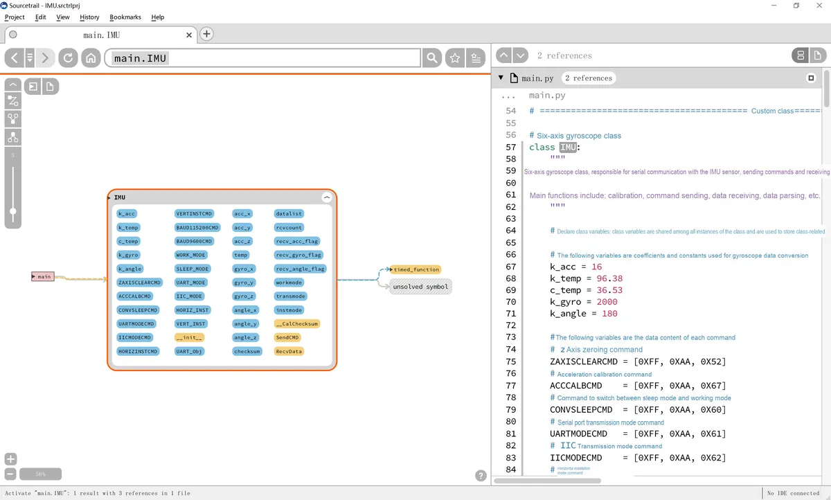
For the basic usage and software description of the visual code reading tool Sourcetrail, you can refer to the following link:
3.2.3.7 Experimental Phenomena
First, we open the SerialPlot debugging software:
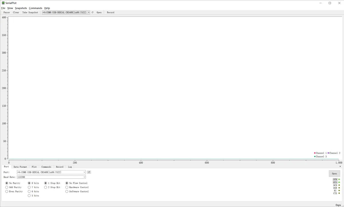
First, set the serial port communication parameters:
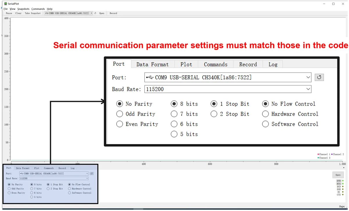
Next, we configure the format of the data to be parsed. Here, what we need to parse are floating-point numbers from three channels, with each channel separated by a comma:
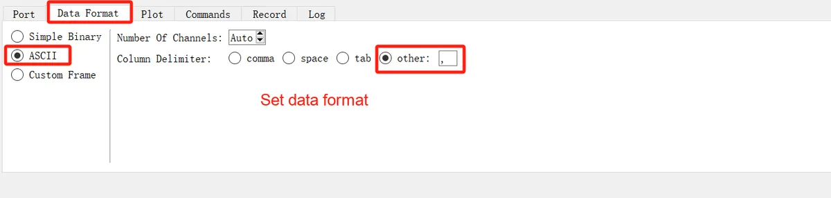
After the setup is complete, click the "Open" button to open it:
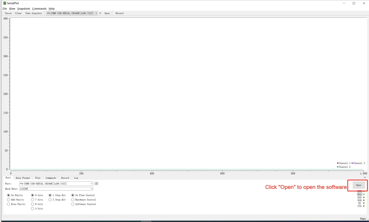
After flashing the program to the Raspberry Pi Pico and connecting to the Raspberry Pi Pico via the terminal, we can see that the function execution time, three-axis angle data and the number of available stack bytes are continuously output, and the LED flashes rapidly at the same time:
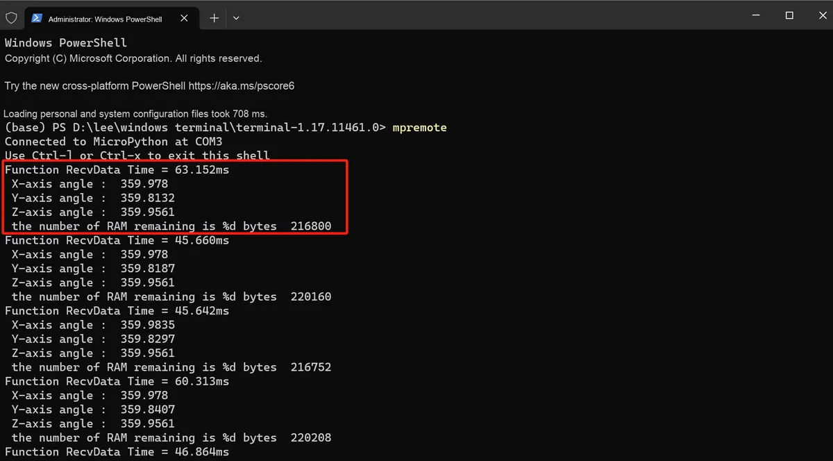
If garbage collection is not used, the number of available bytes in the stack will drop rapidly. We can comment out the following statements and then re-burn and run the program:
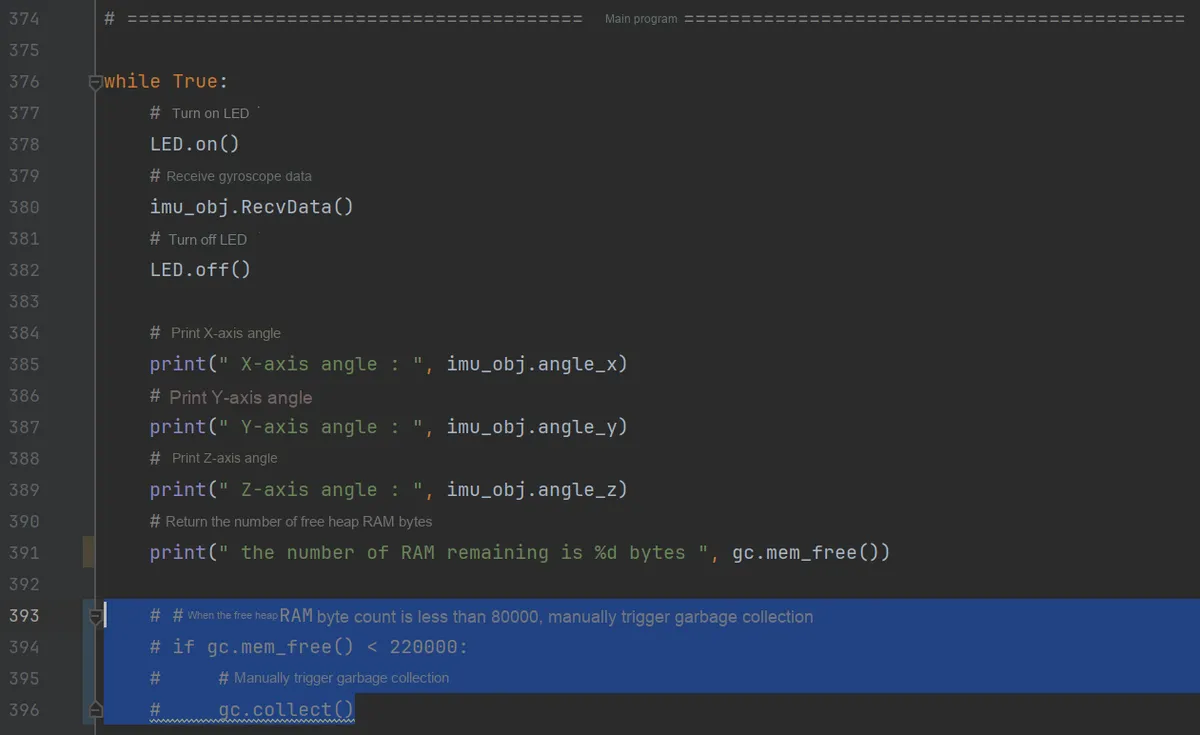
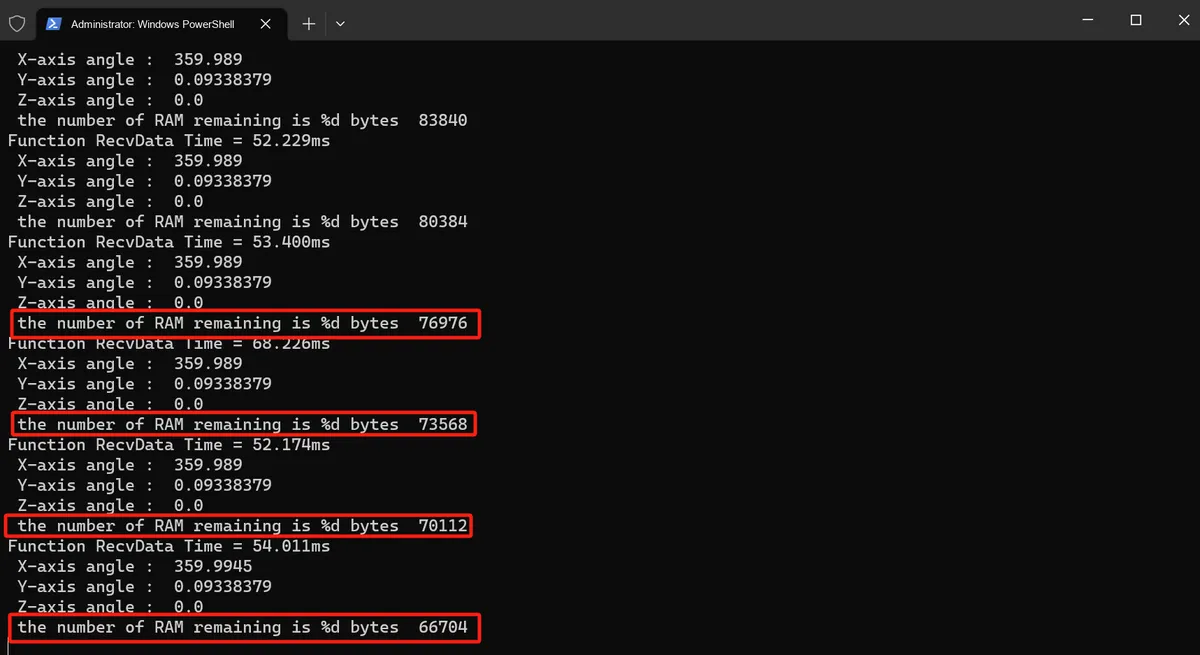
It can be seen that the available stack count drops sharply, and automatic garbage collection is not triggered until it falls to around 1000 bytes. This is mainly because a large number of temporary variables are used as data caches in our code, but not all of these variables are used at the same time — they are only read when needed by the user (for example, the user may only need the current angle value).
Meanwhile, as we shake the gyroscope sensor module, you can also see that SerialPlot the waveform on the debugging software is changing:
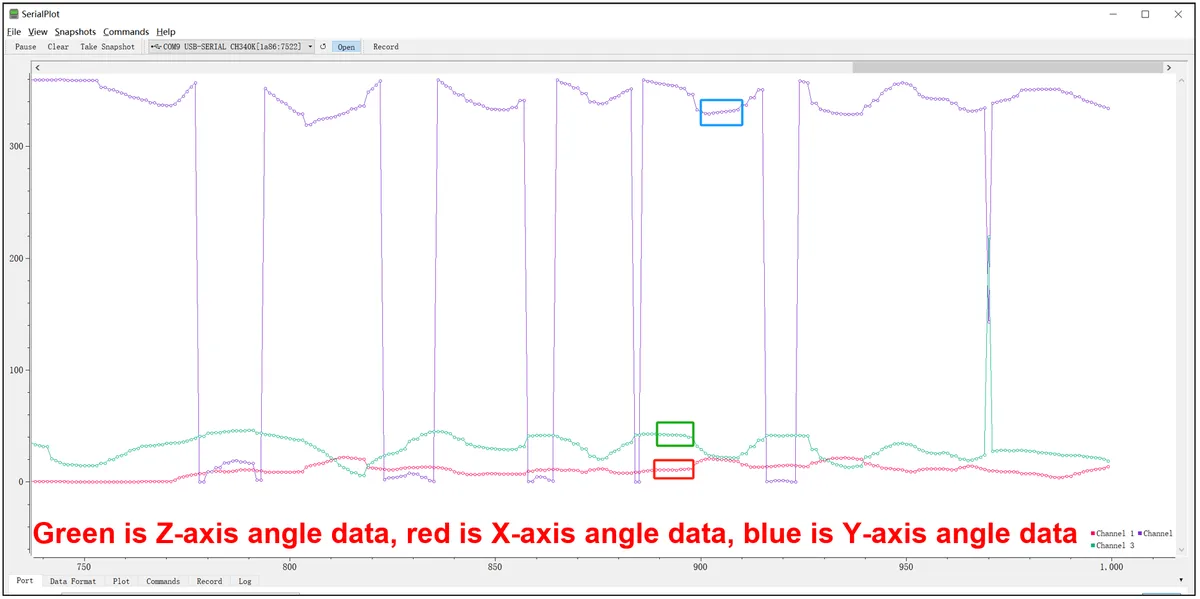
3.2 Application Experiment.mp4 107.0 MB
3.3 Using Serial Port to Drive Serial Servos
3.3.1 Introduction to Serial Servos
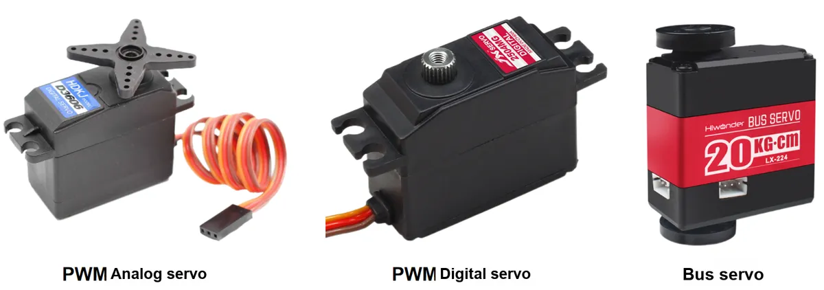
A servo is a position (angle) servo actuator whose core function is to precisely control the rotation angle of the output shaft according to the input signal, and it is widely used in scenarios such as robot joints, model aircraft control surfaces, and smart home robotic arms. In terms of technical iteration, servos have gone through the upgrading path of "PWM analog servo → digital servo → bus servo", with each generation optimized around "control accuracy, communication efficiency, and function scalability".
Regardless of the type of steering gear, its core structure consists of five major modules: signal receiving unit, Control Unit, drive unit, execution unit, and feedback unit, with differences mainly reflected in "signal form" and "the implementation mode of the Control Unit":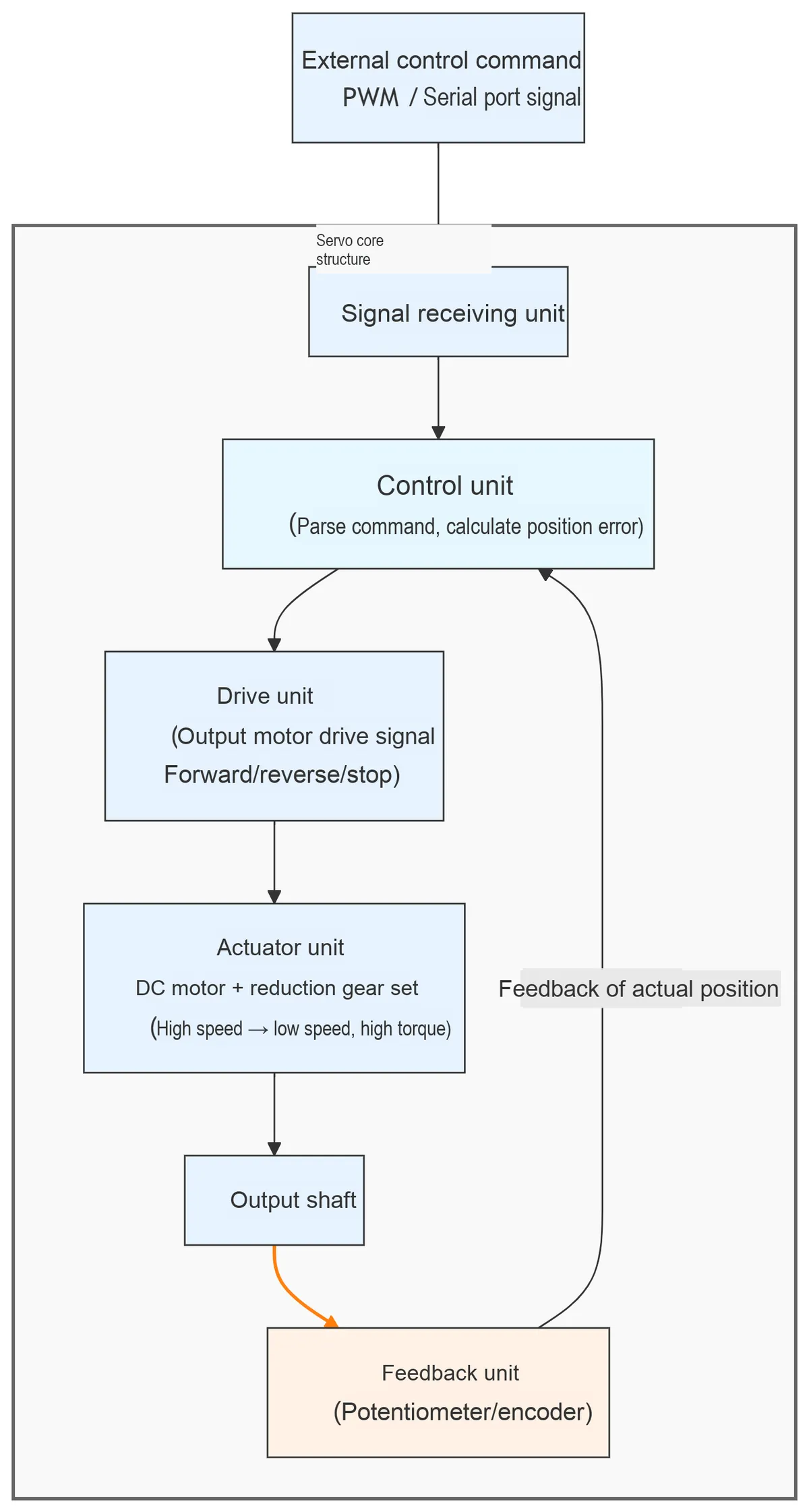
- Signal receiving unit: Receives external control commands (PWM or serial port signals);
- Control Unit: parses instructions and compares the deviation between the current position and the target position;
- Drive Unit: Outputs motor drive signals (forward rotation / reverse rotation / stop) based on the deviation;
- Actuation Unit: Consists of a DC motor + reduction gear set, which converts the high-speed rotation of the motor into low-speed, high-torque rotation of the output shaft;
- Feedback Unit: It detects the actual position of the output shaft via a potentiometer or encoder, and sends a postback to the Control Unit to form a "closed-loop control".
PWM analog servo is the most basic type of servo, which relies on analog circuits to implement closed-loop control. The Control Unit of an analog servo consists of analog circuits such as operational amplifiers, with no digital chips, featuring a simple structure.
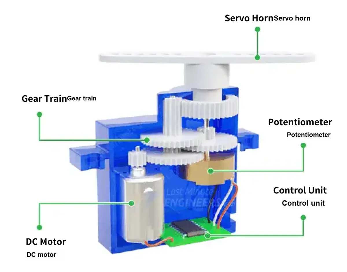
However, PWM analog servos also have the drawbacks of poor control accuracy, slow response speed, no status feedback and weak anti-interference performance.
PWM digital servos are developed based on analog servos by adding an MCU (Micro Control Unit) and replacing part of the analog circuits with "digital circuits", which solves the problems of precision, anti-interference and response of analog servos.
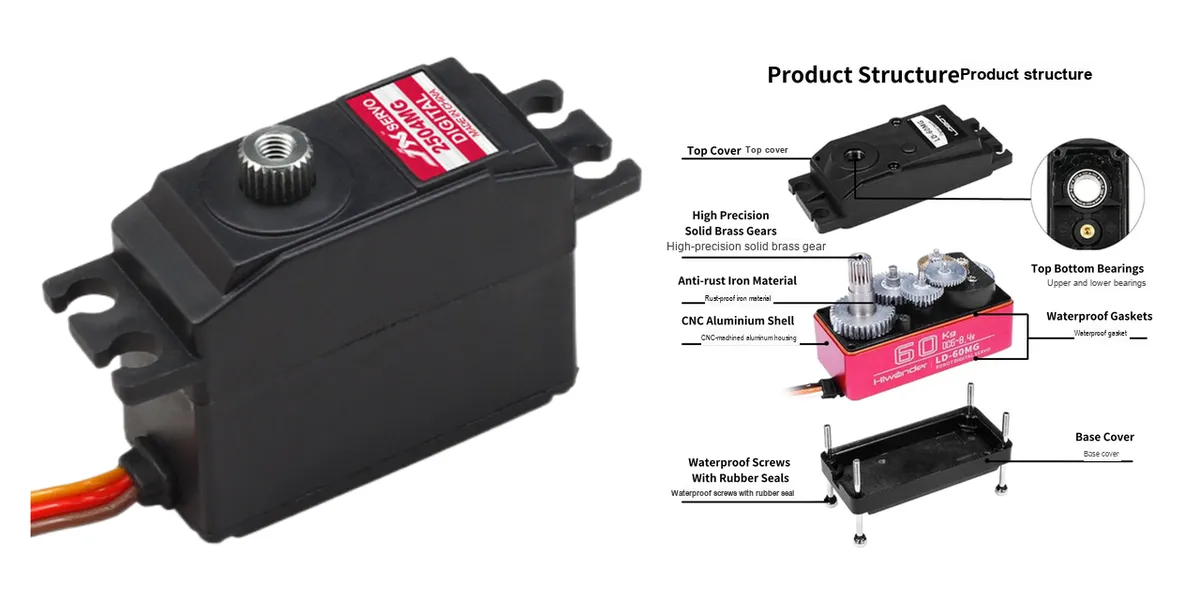
The control signal of the PWM digital servo is still a PWM signal (compatible with the control standard of analog servos), while its internal control logic is fully digitized:
- The "operational amplifier" of the analog servo is replaced by "MCU + digital comparator";
- The analog voltage signal from the potentiometer is converted into a digital signal by the ADC (Analog-to-Digital Converter), which is then sent to the MCU for precise comparison with the target angle.
However, PWM digital servos still rely on PWM simplex communication, which cannot postback status data; meanwhile, multi-servo control remains cumbersome, and just like analog servos, controlling one servo requires occupying one IO port of the MCU. The core breakthrough of bus servos lies in replacing PWM signals with "bus communication", realizing "two-way communication + bus control" and completely reconstructing the control logic of servos.
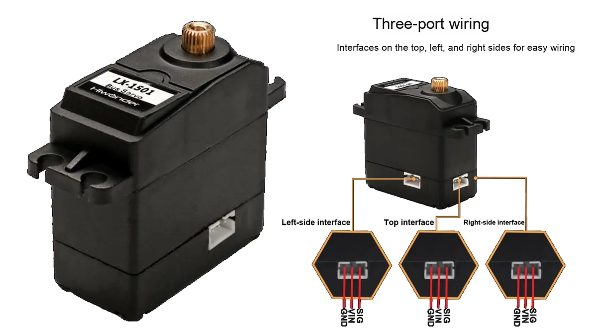
The main control unit obtains the current position and the target position to be reached of the steering gear by sending and receiving command packets, which is a closed-loop control form. The feedbackable parameters include voltage, current, temperature, torque, speed, position, and whether the status of the steering gear is normal.
Common bus servos include the following models:
- RS-485 Serial Servo: Based on differential signal transmission, it features strong anti-interference performance and long transmission distance, making it suitable for industrial and research-grade robots.
- TTL Serial Bus Servo: Directly controlled via the UART of a microcontroller, featuring simple wiring and low cost, it is commonly used in educational robots and open-source projects.
- CAN Bus Servo: Adopts the CAN bus protocol, featuring high reliability and strong scalability, and is widely used in automotive electronics and industrial robots.
Bus servos support independent address setting (e. g., configuring addresses 0 to 255 via dip switches or commands), and multiple servos can share one set of serial bus (TX transmission line, RX reception line, GND ground line):
- When the host sends a command, the frame contains the "target servo address";
- After all the servos on the bus receive the command, they first parse the address — only the servo that matches its own address executes the command, while all other servos ignore it;
- When the servo posts back data, the frame contains its own address, so the host can identify the data source.
Next, taking the LX-1501 bus servo motor from Hiwonder as an example, we will explain how to read, write and control the serial servo motor via custom serial protocol frames. The Hiwonder LX-1501 intelligent bus servo motor integrates servo drive, motor and bus servo signals into one unit, receives command control through the half-duplex UART asynchronous serial interface, with a serial baud rate of 115200. Users can send commands in accordance with the Communication Protocol to realize servo rotation and information reading, and can also switch to the stepping motor mode.This servo motor supports multi-motor series connection (with a theoretical maximum of 253 units in series), and is widely used in robot projects requiring closed-loop control such as bionic robot joints.
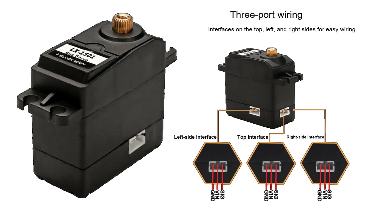
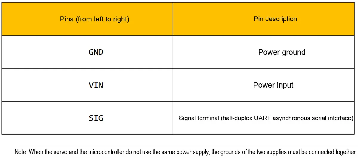
LX-1501 has the following key parameters:
- Power and Performance: Rated operating voltage: 7.4V (range: 6 - 8.4V), stall torque: 17kg.cm, rotation speed: 0.16s/60°(at 7.4V), control angle range: 0 - 1000 (corresponding to actual 0°~240°), accuracy up to 0.3°;
- Functions and Protections: Supports power-off saving of user settings and angle readback, can feed back parameters such as temperature, voltage and position, and features stall protection and over temperature protection;
- Configuration and Specifications: The default ID is 1 (configurable within the range of 0 - 253), it adopts metal gears, comes with a 20cm PH2.0-3P connector (cable length optional), measures 40×20.0×40.5mm in product dimensions, and weighs 58g.
The following key points shall be followed during use:
- Power Adaptation: Select a stable power supply within the range of 6 - 8.4V; overvoltage will burn out the steering gear, while undervoltage will fail to drive it properly.
- ID Setting: The factory default ID is 1, which needs to be preset as required before use. When setting the ID, connect the servo individually (to avoid all servos being set to the same ID when connected in series), and then connect them in series after the setting is completed.
- Mechanical and Heat Dissipation Protection: Do not forcibly twist the servo arm or servo disc after power-on to avoid damaging the internal structure; the servo will generate heat after continuous operation, so timely cooling is required to prevent overheating from affecting its performance and service life.
- Load Limit: During continuous rotation, the load shall be 1/3 to 1/5 of the stall torque (stall torque refers to the maximum torque of the servo when it cannot rotate; excessive load will increase energy consumption and reduce efficiency).
For additional details, please refer to the materials we provided; no further elaboration will be given here.
3.3.2 Hiwonder Serial Bus Servo Communication Protocol Introduction
The bus servo Communication Protocol is the "language specification" for the interaction between the driver and the servo, and all control commands (such as rotation angle, temperature reading) and status feedback need to be transmitted in accordance with the protocol format. This protocol is based on half-duplex UART asynchronous communication, supports series control of 253 servos, has a fixed baud rate of 115200bps, and its core realizes function control through the process of "command frame packaging - transmission - response frame parsing".
All commands and responses follow a unified frame structure, and the driver shall process data in the order of fields to ensure that the steering gear can recognize the commands and the responses can be parsed.
Field | Number of bytes | Function Description | Key Points Related to Driver Development |
Frame Header | 2 | Instruction start identifier, fixed as | When parsing the response, first check for two consecutive |
ID | 1 | Target servo ID (0~253) or broadcast ID (0xFE) | When packaging instructions, the ID passed by the user needs to be received; the broadcast ID instruction does not respond (except for the read-only ID instruction) |
data length | 1 | Value = Total number of bytes of "command + parameters"(including itself) | Total frame length = data length + 3; the driver can verify the frame integrity via this value to avoid parsing errors caused by broken frames. |
Instruction | 1 | Function identifier (e. g. rotation, temperature reading) | It is necessary to define an instruction constant mapping table (e. g., |
Parameters | N | Supplementary instruction information (e. g. angle, time) | Split / concatenate according to instruction type (e. g., split a 16-bit angle into high and low 8 bits), and some require signed/unsigned conversion |
checksum | 1 | Ensure correct data transmission | The calculation and verification function must be implemented; otherwise, the command will be discarded by the servo (calculation formula: |
Protocols are categorized by function into "write commands (configuration/control)" and "read commands (status acquisition)":
- Write command: suffix
_WRITE, with parameters (e. g. setting angle), no response after execution (no need to wait after the driver sends it); - Read instruction: suffix
_READ, no parameters (e. g. read temperature), a response will be returned after execution (the driver needs to receive and parse it immediately).
The specific instructions are as follows:
| Instruction type | Instruction name | Command value | Data length | Core function | Parameter description |
|---|---|---|---|---|---|
| Write command | SERVO_MOVE_TIME_WRITE | 1 | 7 | The servo rotates at a constant speed from its current angle to the target angle within the specified time; executes immediately when the command arrives | Parameter 1: angle low 8 bits; Parameter 2: angle high 8 bits (0~1000 corresponds to 0~240°); Parameter 3: time low 8 bits; Parameter 4: time high 8 bits (0~30000ms) |
| Read command | SERVO_MOVE_TIME_READ | 2 | 3 | Reads the angle and time values set by the SERVO_MOVE_TIME_WRITE command | Response parameters: angle low 8 bits, angle high 8 bits, time low 8 bits, time high 8 bits |
| Write command | SERVO_MOVE_TIME_WAIT_WRITE | 7 | 7 | Presets the servo target angle and rotation time; not executed when the command arrives, waits for a start command to trigger it | Parameter 1: preset angle low 8 bits; Parameter 2: preset angle high 8 bits (0~1000 corresponds to 0~240°); Parameter 3: preset time low 8 bits; Parameter 4: preset time high 8 bits (0~30000ms) |
| Read command | SERVO_MOVE_TIME_WAIT_READ | 8 | 3 | Reads the angle and time values preset by the SERVO_MOVE_TIME_WAIT_WRITE command | Response parameters: preset angle low 8 bits, preset angle high 8 bits, preset time low 8 bits, preset time high 8 bits |
| Write command | SERVO_MOVE_START | 11 | 3 | Triggers the rotation preset by the SERVO_MOVE_TIME_WAIT_WRITE command | No parameters |
| Write command | SERVO_MOVE_STOP | 12 | 3 | Stops the servo immediately and locks the current angle | No parameters |
| Write command | SERVO_ID_WRITE | 13 | 4 | Changes the servo ID, saved on power-off | Parameter 1: new ID value (0~253, default 1) |
| Read command | SERVO_ID_READ | 14 | 3 | Reads the current servo ID (when sent with the broadcast ID, only this read command returns a response) | Response parameter 1: current ID value |
| Write command | SERVO_ANGLE_OFFSET_ADJUST | 17 | 4 | Adjusts the servo angle offset, takes effect immediately, not saved on power-off | Parameter 1: offset value (-125~125 corresponds to -30°~30°, must be converted to unsigned char before sending) |
| Write command | SERVO_ANGLE_OFFSET_WRITE | 18 | 3 | Saves the offset value set by SERVO_ANGLE_OFFSET_ADJUST, saved on power-off | No parameters |
| Read command | SERVO_ANGLE_OFFSET_READ | 19 | 3 | Reads the servo angle offset value that has been set | Response parameter 1: current offset value (-125~125) |
| Write command | SERVO_ANGLE_LIMIT_WRITE | 20 | 7 | Sets the servo rotation angle range, saved on power-off | Parameter 1: minimum angle low 8 bits; Parameter 2: minimum angle high 8 bits; Parameter 3: maximum angle low 8 bits; Parameter 4: maximum angle high 8 bits (all 0~1000, minimum < maximum) |
| Read command | SERVO_ANGLE_LIMIT_READ | 21 | 3 | Reads the servo angle limit range values | Response parameters: minimum angle low 8 bits, minimum angle high 8 bits, maximum angle low 8 bits, maximum angle high 8 bits |
| Write command | SERVO_VIN_LIMIT_WRITE | 22 | 7 | Sets the servo input voltage limit range, saved on power-off; if out of range, the motor unloads and raises an alarm | Parameter 1: minimum voltage low 8 bits; Parameter 2: minimum voltage high 8 bits; Parameter 3: maximum voltage low 8 bits; Parameter 4: maximum voltage high 8 bits (all 4500~12000mV, minimum < maximum) |
| Read command | SERVO_VIN_LIMIT_READ | 23 | 3 | Reads the servo input voltage limit range values | Response parameters: minimum voltage low 8 bits, minimum voltage high 8 bits, maximum voltage low 8 bits, maximum voltage high 8 bits |
| Write command | SERVO_TEMP_MAX_LIMIT_WRITE | 24 | 4 | Sets the servo maximum temperature limit, saved on power-off; if over temperature, the motor unloads and raises an alarm | Parameter 1: maximum temperature value (50~100℃, default 85℃) |
| Read command | SERVO_TEMP_MAX_LIMIT_READ | 25 | 3 | Reads the servo maximum temperature limit value | Response parameter 1: current maximum temperature limit value |
| Read command | SERVO_TEMP_READ | 26 | 3 | Reads the servo internal real-time temperature | Response parameter 1: current temperature value (℃) |
| Read command | SERVO_VIN_READ | 27 | 3 | Reads the servo current input voltage value | Response parameter 1: voltage low 8 bits; Parameter 2: voltage high 8 bits (unit: mV) |
| Read command | SERVO_POS_READ | 28 | 3 | Reads the servo current actual angle position | Response parameter 1: angle low 8 bits; Parameter 2: angle high 8 bits (must be converted to signed short, may be negative) |
| Write command | SERVO_OR_MOTOR_MODE_WRITE | 29 | 7 | Sets the servo working mode (position / motor) and motor speed, not saved on power-off | Parameter 1: mode (0 = position, 1 = motor); Parameter 2: null value (0); Parameter 3: speed low 8 bits; Parameter 4: speed high 8 bits (-1000~1000, must be converted to unsigned short) |
| Read command | SERVO_OR_MOTOR_MODE_READ | 30 | 3 | Reads the servo current working mode and speed parameters | Response parameters: mode, null value (0), speed low 8 bits, speed high 8 bits |
| Write command | SERVO_LOAD_OR_UNLOAD_WRITE | 31 | 4 | Sets the servo motor load / unload state (torque / no torque) | Parameter 1: state (0 = unloaded, power off, 1 = loaded, with torque, default 0) |
| Read command | SERVO_LOAD_OR_UNLOAD_READ | 32 | 3 | Reads the servo motor load / unload state | Response parameter 1: current state value |
| Write command | SERVO_LED_CTRL_WRITE | 33 | 4 | Sets the servo LED on/off state, saved on power-off | Parameter 1: state (0 = always on, 1 = always off, default 0) |
| Read command | SERVO_LED_CTRL_READ | 34 | 3 | Reads the servo LED current state | Response parameter 1: current state value |
| Write command | SERVO_LED_ERROR_WRITE | 35 | 4 | Sets which faults trigger the LED flashing alarm | Parameter 1: fault flag (0~7, corresponds to combinations of over-temperature / over-voltage / stall, see Table 3) |
| Read command | SERVO_LED_ERROR_READ | 36 | 3 | Reads the current fault alarm trigger configuration or real-time fault status | Response parameter 1: current fault flag value (0~7) |
3.3.2 Serial Port Control Experiment on HiWonder LX-1501 Bus Servo
3.3.3.1 Brief Introduction to the Code of the SerialServo Serial Port Servo Driver Class
First, we define a SerialServo serial servo driver class, which has the following methods:
| Method name | Description |
| __init__(self, uart: UART) -> None | Initializes the serial servo control class; takes a UART object as a parameter and establishes the basis for communication with the servo |
| calculate_checksum(data: list[int]) -> int | Calculates the checksum of the data, used to verify the integrity and correctness of command packets / response packets |
| build_packet(servo_id: int, cmd: int, params: list[int]) -> bytearray | Builds a servo control command packet, combining the frame header, ID, command, parameters and checksum according to the protocol format |
| send_command(servo_id: int, cmd: int, params: list[int] = []) -> None | Sends a control command to the servo with the specified ID; internally calls build_packet to generate the command packet and sends it via UART |
| receive_command(expected_cmd: int, expected_data_len: int) -> list | Receives the response packet returned by the servo, parses and verifies the data, and returns valid data that matches the expected command and length |
| move_servo_immediate(servo_id: int, angle: float, time_ms: int) -> None | Controls the specified servo to rotate immediately to the target angle (physical angle), completing within the specified time (milliseconds) |
| get_servo_move_immediate(servo_id: int) -> tuple | Gets the target angle and rotation time set for the specified servo via move_servo_immediate, returned as a tuple |
| move_servo_with_time_delay(servo_id: int, angle: float, time_ms: int) -> None | Presets the target angle and rotation time of the specified servo; not executed immediately after the command is sent, waits for a start command |
| get_servo_move_with_time_delay(servo_id: int) -> tuple | Gets the angle and time preset for the specified servo via move_servo_with_time_delay, returned as a tuple |
| start_servo(servo_id: int) -> None | Starts the delayed rotation of the specified servo (used together with move_servo_with_time_delay), triggering the preset rotation |
| stop_servo(servo_id: int) -> None | Immediately stops the rotation of the specified servo and locks it at the current angle position |
| set_servo_id(servo_id: int, new_id: int) -> None | Sets a new ID (range 0~253) for the specified servo, saved on power-off |
| get_servo_id(servo_id: int) -> int | Gets the current ID value of the specified servo |
| set_servo_angle_offset(servo_id: int, angle: float, save_to_memory: bool = False) -> None | Adjusts the angle offset of the specified servo (physical angle); when save_to_memory is True, the offset value is saved on power-off |
| get_servo_angle_offset(servo_id: int) -> float | Gets the current angle offset value of the specified servo (physical angle) |
| set_servo_angle_range(servo_id: int, min_angle: float, max_angle: float) -> None | Sets the minimum and maximum rotation angle limits of the specified servo (physical angle), saved on power-off |
| get_servo_angle_range(servo_id: int) -> tuple | Gets the angle limit range of the specified servo, returns a (minimum angle, maximum angle) tuple (physical angle) |
| set_servo_vin_range(servo_id: int, min_vin: float, max_vin: float) -> None | Sets the minimum and maximum input voltage limits of the specified servo (unit: V), saved on power-off |
| get_servo_vin_range(servo_id: int) -> tuple | Gets the voltage limit range of the specified servo, returns a (minimum voltage, maximum voltage) tuple (unit: V) |
| set_servo_temp_range(servo_id: int, max_temp: int) -> None | Sets the maximum temperature limit of the specified servo (unit: ℃), saved on power-off; protection is triggered when over temperature |
| get_servo_temp_range(servo_id: int) -> int | Gets the maximum temperature limit value of the specified servo (unit: ℃) |
| read_servo_temp(servo_id: int) -> int | Reads the real-time internal temperature of the specified servo (unit: ℃) |
| read_servo_voltage(servo_id: int) -> float | Reads the real-time input voltage of the specified servo (unit: V) |
| read_servo_pos(servo_id: int) -> float | Reads the current actual angle position of the specified servo (physical angle) |
| set_servo_mode_and_speed(servo_id: int, mode: int, speed: int) -> None | Sets the working mode of the specified servo (0 = position mode, 1 = motor mode) and motor speed (-1000~1000), not saved on power-off |
| get_servo_mode_and_speed(servo_id: int) -> tuple | Gets the current working mode and speed of the specified servo, returns a (mode, speed) tuple |
| set_servo_motor_load(servo_id: int, unload: bool) -> None | Sets the motor state of the specified servo: unload=True unloads and powers off (no torque), False loads (with torque) |
| get_servo_motor_load_status(servo_id: int) -> bool | Gets the motor state of the specified servo: returns True for unloaded, False for loaded |
| set_servo_led(servo_id: int, led_on: bool) -> None | Sets the LED state of the specified servo: led_on=True is always on, False is always off, saved on power-off |
| get_servo_led(servo_id: int) -> bool | Gets the LED state of the specified servo: returns True for always on, False for always off |
| set_servo_led_alarm(servo_id: int, alarm_code: int) -> None | Sets the fault types that trigger LED flashing for the specified servo (0~7, corresponds to combinations of over-temperature / over-voltage / stall), saved on power-off |
| get_servo_led_alarm(servo_id: int) -> int | Gets the LED fault alarm configuration or real-time fault status of the specified servo (returns a fault code of 0~7) |
This class encapsulates all functions related to steering gear control, including generating and sending control commands, receiving steering gear feedback, and reading steering gear status.
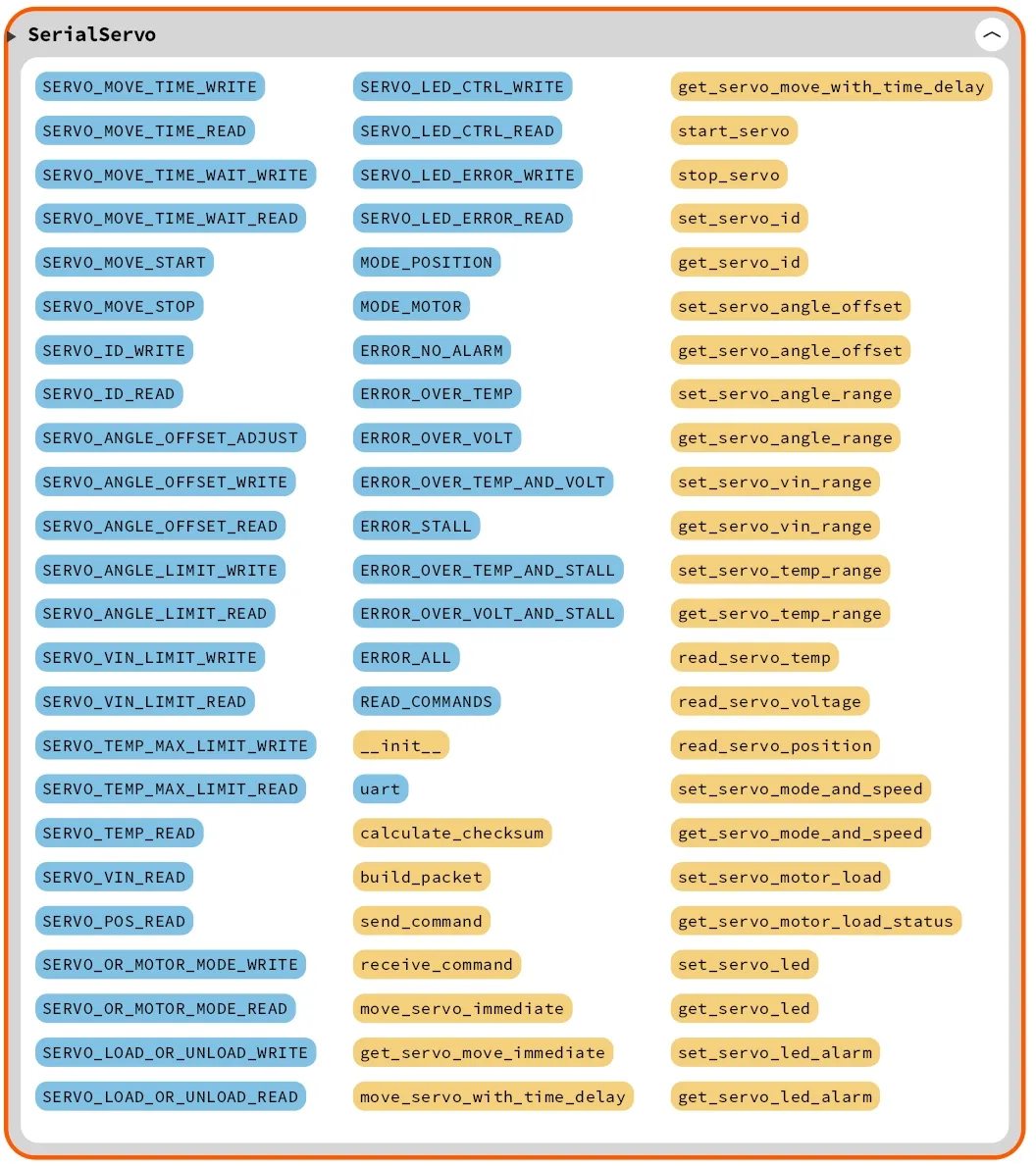
Here, we first define the length of instructions and their parameters, or the length of returned data, as class constants:
# Custom class for serial bus servo
class SerialServo:
    """
    Serial bus servo control class, used to generate and send control commands.

    This class communicates with the servo over UART, and supports building control command packets, calculating checksums, and sending commands.
    Supports adjustable baud rates and control of different servos.

    Attributes:
        uart (machine.UART): UART instance used to communicate with the servo.

    Class Variables:
        - Definitions of command and parameter lengths or return data lengths.
        - Definitions of various servo control commands, including write commands and read commands.
        - Definitions of servo working modes.
        - Definitions of LED alarm fault types.

    Methods:
        calculate_checksum(data: list[int]) -> int:
            Calculate the checksum to ensure data integrity and correctness.
        build_packet(servo_id: int, cmd: int, params: list[int]) -> bytearray:
            Build the servo command packet.
        send_command(servo_id: int, cmd: int, params: list[int] = []) -> None:
            Send a control command to the servo.
        receive_command(expected_cmd: int, expected_data_len: int) -> list:
            Receive and process the command data packet returned by the servo.
        move_servo_immediate(servo_id: int, angle: float, time_ms: int) -> None:
            Immediately control the servo to rotate to the specified angle.
        get_servo_move_immediate(servo_id: int) -> tuple:
            Get the preset angle and time of the servo.
        move_servo_with_time_delay(servo_id: int, angle: float, time_ms: int) -> None:
            Control the servo to rotate to the specified angle after a delay.
        get_servo_move_with_time_delay(servo_id: int) -> tuple:
            Get the preset angle and time of the servo (delayed rotation).
        start_servo(servo_id: int) -> None:
            Start the servo rotation.
        stop_servo(servo_id: int) -> None:
            Immediately stop the servo rotation and hold at the current angle position.
        set_servo_id(servo_id: int, new_id: int) -> None:
            Set a new ID value for the servo.
        get_servo_id(servo_id: int) -> int:
            Get the servo ID.
        set_servo_angle_offset(servo_id: int, angle: float, save_to_memory: bool = False) -> None:
            Adjust the servo deviation according to the angle value.
        get_servo_angle_offset(servo_id: int) -> float:
            Get the servo deviation angle.
        set_servo_angle_range(servo_id: int, min_angle: float, max_angle: float) -> None:
            Set the minimum and maximum angle limits of the servo.
        get_servo_angle_range(servo_id: int) -> tuple:
            Get the angle limits of the servo.
        set_servo_vin_range(servo_id: int, min_vin: float, max_vin: float) -> None:
            Set the minimum and maximum input voltage limits of the servo.
        get_servo_vin_range(servo_id: int) -> tuple:
            Get the voltage limit values of the servo.
        set_servo_temp_range(servo_id: int, max_temp: int) -> None:
            Set the maximum temperature limit of the servo.
        get_servo_temp_range(servo_id: int) -> int:
            Get the internal maximum temperature limit value of the servo.
        read_servo_temp(servo_id: int) -> int:
            Get the real-time temperature of the servo.
        read_servo_voltage(servo_id: int) -> float:
            Get the real-time input voltage of the servo.
        read_serv:pos_read(servo_id: int) -> float:
            Get the real-time angle position of the servo.
        set_servo_mode_and_speed(servo_id: int, mode: int, speed: int) -> None:
            Set the working mode and motor speed of the servo.
        get_servo_mode_and_speed(servo_id: int) -> tuple:
            Get the working mode and rotation speed of the servo.
        set_servo_motor_load(servo_id: int, unload: bool) -> None:
            Set whether the servo motor is unloaded (power off).
        get_servo_motor_load_status(servo_id: int) -> bool:
            Get whether the servo motor is loaded or unloaded.
        set_servo_led(servo_id: int, led_on: bool) -> None:
            Set the on/off state of the servo LED.
        get_servo_led(servo_id: int) -> bool:
            Get the on/off state of the servo LED.
        set_servo_led_alarm(servo_id: int, alarm_code: int) -> None:
            Set the fault values that trigger the servo LED flashing alarm.
        get_servo_led_alarm(servo_id: int) -> int:
            Get the servo LED fault alarm status.

    =================================================

        SerialServo Class:
    A class to control the serial servo, used to generate and send control commands.

    This class communicates with the servo through UART serial, supporting the construction of control command packets,
    checksum calculation, and command sending.
    It supports adjustable baud rates and control for various servo models.

    Attributes:
        uart (machine.UART): UART instance for communication with the servo.

    Class Variables:
        - Definitions of command lengths or return data lengths.
        - Definitions of various servo control commands, including write and read commands.
        - Definitions of servo working modes.
        - Definitions of LED alarm fault types.

    Methods:
        calculate_checksum(data: list[int]) -> int:
            Calculate checksum to ensure data integrity and correctness.
        build_packet(servo_id: int, cmd: int, params: list[int]) -> bytearray:
            Construct servo control command packet.
        send_command(servo_id: int, cmd: int, params: list[int] = []) -> None:
            Send control command to the servo.
        receive_command(expected_cmd: int, expected_data_len: int) -> list:
            Receive and process the response from the servo.
        move_servo_immediate(servo_id: int, angle: float, time_ms: int) -> None:
            Control the servo to move immediately to a specified angle.
        get_servo_move_immediate(servo_id: int) -> tuple:
            Get the servo's preset angle and time for immediate movement.
        move_servo_with_time_delay(servo_id: int, angle: float, time_ms: int) -> None:
            Control the servo to move to a specified angle with a delay.
        get_servo_move_with_time_delay(servo_id: int) -> tuple:
            Get the servo's preset angle and time for delayed movement.
        start_servo(servo_id: int) -> None:
            Start the servo's movement.
        stop_servo(servo_id: int) -> None:
            Immediately stop the servo and hold at the current position.
        set_servo_id(servo_id: int, new_id: int) -> None:
            Set a new ID for the servo.
        get_servo_id(servo_id: int) -> int:
            Get the current ID of the servo.
        set_servo_angle_offset(servo_id: int, angle: float, save_to_memory: bool = False) -> None:
            Adjust the servo's angle offset based on a specified angle.
        get_servo_angle_offset(servo_id: int) -> float:
            Get the current angle offset of the servo.
        set_servo_angle_range(servo_id: int, min_angle: float, max_angle: float) -> None:
            Set the minimum and maximum angle limits for the servo.
        get_servo_angle_range(servo_id: int) -> tuple:
            Get the current angle limits of the servo.
        set_servo_vin_range(servo_id: int, min_vin: float, max_vin: float) -> None:
            Set the minimum and maximum input voltage range for the servo.
        get_servo_vin_range(servo_id: int) -> tuple:
            Get the current input voltage range of the servo.
        set_servo_temp_range(servo_id: int, max_temp: int) -> None:
            Set the maximum temperature limit for the servo.
        get_servo_temp_range(servo_id: int) -> int:
            Get the current maximum temperature limit for the servo.
        read_servo_temp(servo_id: int) -> int:
            Read the current temperature of the servo.
        read_servo_voltage(servo_id: int) -> float:
            Read the current input voltage of the servo.
        read_servo_pos(servo_id: int) -> float:
            Read the current angle position of the servo.
        set_servo_mode_and_speed(servo_id: int, mode: int, speed: int) -> None:
            Set the working mode and motor speed for the servo.
        get_servo_mode_and_speed(servo_id: int) -> tuple:
            Get the current working mode and motor speed of the servo.
        set_servo_motor_load(servo_id: int, unload: bool) -> None:
            Set whether the servo motor is loaded or unloaded.
        get_servo_motor_load_status(servo_id: int) -> bool:
            Get the current load status of the servo motor.
        set_servo_led(servo_id: int, led_on: bool) -> None:
            Set the LED light status (on/off) of the servo.
        get_servo_led(servo_id: int) -> bool:
            Get the current LED light status of the servo.
        set_servo_led_alarm(servo_id: int, alarm_code: int) -> None:
            Set the LED alarm fault code for the servo.
        get_servo_led_alarm(servo_id: int) -> int:
            Get the current LED alarm fault code of the servo.

    """

    # Class variables: command and parameter lengths or return data lengths
    # Write commands and their corresponding parameter lengths
    # Read commands and their corresponding parameter lengths and return data lengths

    # Servo immediate rotation write command
    SERVO_MOVE_TIME_WRITE = (1, 7)
    # Servo immediate rotation parameter read command
    SERVO_MOVE_TIME_READ = (2, 3, 7)

    # Servo delayed rotation write command
    SERVO_MOVE_TIME_WAIT_WRITE = (7, 7)
    # Servo delayed rotation read command
    SERVO_MOVE_TIME_WAIT_READ = (8, 3, 7)

    # Servo start rotation command (used together with the SERVO_MOVE_TIME_WAIT_WRITE command)
    SERVO_MOVE_START = (11, 3)
    # Servo stop rotation command
    SERVO_MOVE_STOP = (12, 3)

    # Servo ID write command (supports saving on power loss)
    SERVO_ID_WRITE = (13, 4)
    # Servo ID read command
    SERVO_ID_READ = (14, 3, 4)

    # Servo deviation adjustment command (does not support saving on power loss)
    SERVO_ANGLE_OFFSET_ADJUST = (17, 4)
    # Servo deviation adjustment command (supports saving on power loss)
    SERVO_ANGLE_OFFSET_WRITE = (18, 3)
    # Servo deviation adjustment read command
    SERVO_ANGLE_OFFSET_READ = (19, 3, 4)

    # Servo angle limit write command (supports saving on power loss)
    SERVO_ANGLE_LIMIT_WRITE = (20, 7)
    # Servo angle limit read command
    SERVO_ANGLE_LIMIT_READ = (21, 3, 7)

    # Servo voltage limit write command (supports saving on power loss)
    SERVO_VIN_LIMIT_WRITE = (22, 7)
    # Servo voltage limit read command
    SERVO_VIN_LIMIT_READ = (23, 3, 7)

    # Servo temperature limit write command (supports power-off save)
    SERVO_TEMP_MAX_LIMIT_WRITE = (24, 4)
    # Servo temperature limit read command
    SERVO_TEMP_MAX_LIMIT_READ = (25, 3, 4)

    # Servo real-time temperature read command
    SERVO_TEMP_READ = (26, 3, 4)
    # Servo real-time voltage read command
    SERVO_VIN_READ = (27, 3, 5)
    # Servo current angle read command
    SERVO_POS_READ = (28, 3, 5)

    # Servo mode switch command (does not support power-off save)
    SERVO_OR_MOTOR_MODE_WRITE = (29, 7)
    # Servo mode and parameter read command
    SERVO_OR_MOTOR_MODE_READ = (30, 3, 7)

    # Servo power-on/power-off control command (does not support power-off save)
    SERVO_LOAD_OR_UNLOAD_WRITE = (31, 4)
    # Servo power-on/power-off read command
    SERVO_LOAD_OR_UNLOAD_READ = (32, 3, 4)

    # Servo LED control command (supports power-off save)
    SERVO_LED_CTRL_WRITE = (33, 4)
    # Servo LED read command
    SERVO_LED_CTRL_READ = (34, 3, 4)

    # Servo LED alarm flashing command
    SERVO_LED_ERROR_WRITE = (35, 4)
    # Servo LED alarm flashing value read command
    SERVO_LED_ERROR_READ = (36, 3, 4)

    # Class variable: servo operating mode
    # 0 means position control mode
    MODE_POSITION = 0
    # 1 means motor control mode
    MODE_MOTOR = 1

    # Class variable: LED alarm fault type
    ERROR_NO_ALARM = 0              # No alarm
    ERROR_OVER_TEMP = 1             # Over-temperature alarm
    ERROR_OVER_VOLT = 2             # Over-voltage alarm
    ERROR_OVER_TEMP_AND_VOLT = 3    # Over-temperature and over-voltage alarm
    ERROR_STALL = 4                 # Stall alarm
    ERROR_OVER_TEMP_AND_STALL = 5   # Over-temperature and stall alarm
    ERROR_OVER_VOLT_AND_STALL = 6   # Over-voltage and stall alarm
    ERROR_ALL = 7                   # Over-temperature, over-voltage, and stall alarm

    # Read command set: the tuple length of each command determines which ones are read commands (command number, parameter length, return data length)
    READ_COMMANDS = {
        2,  # SERVO_MOVE_TIME_READ
        8,  # SERVO_MOVE_TIME_WAIT_READ
        14, # SERVO_ID_READ
        19, # SERVO_ANGLE_OFFSET_READ
        21, # SERVO_ANGLE_LIMIT_READ
        23, # SERVO_VIN_LIMIT_READ
        25, # SERVO_TEMP_MAX_LIMIT_READ
        26, # SERVO_TEMP_READ
        27, # SERVO_VIN_READ
        28, # SERVO_POS_READ
        30, # SERVO_OR_MOTOR_MODE_READ
        32, # SERVO_LOAD_OR_UNLOAD_READ
        34, # SERVO_LED_CTRL_READ
        36  # SERVO_LED_ERROR_READ
    }
For example:
SERVO_MOVE_TIME_WRITEandSERVO_MOVE_TIME_READare commands related to servo position control and their parameter formats.SERVO_ID_WRITEandSERVO_ID_READare read and write commands related to the servo ID.
These constant helper classes ensure that correct instructions are sent and returned data is properly parsed during communication.
READ_COMMANDS set defines the numbers of all read commands, which correspond to the data read requests of the servo, such as reading the real-time voltage, angle, temperature and other information of the servo. This set facilitates the judgment in the receive_command () method whether the received data is the expected read command.
In the initialization method, we only need to bind the UART instance that has been initialized externally:
    def __init__(self, uart: UART) -> None:
        """
        Initialize the serial servo control class.

        Args:
            uart (UART): The UART instance to use.

        ===================================================

        Initialize the Serial Servo Control Class.

        Args:
            uart (UART): The UART instance used for communication with the servo.

        """
        self.uart = uart
The core methods of the serial servo class are as follows:
- Packet Construction Method
build_packet: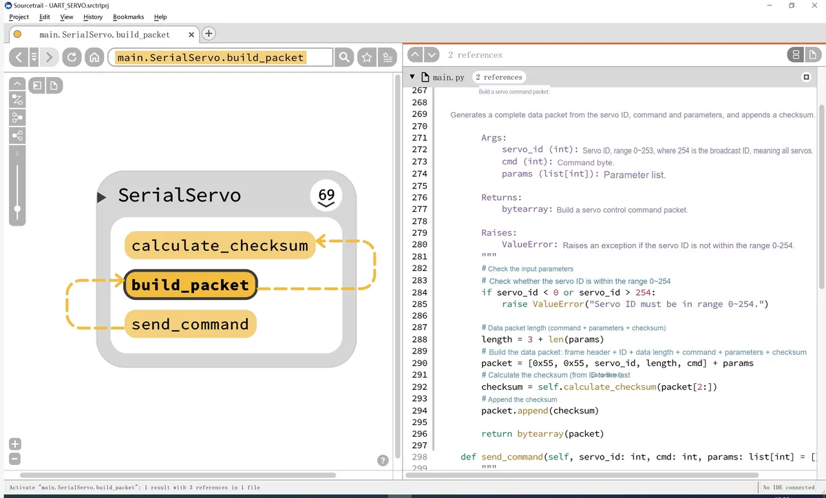
This method is used to construct the command packet for steering gear control, which consists of the following parts:
- Frame Header: Fixed as 0x55,0x55
- Servo ID: uniquely identifies each servo
- Data length: including instructions and parameters
- Instruction No.: Specific control instruction
- Parameter: the parameter of the control instruction
- Checksum: Used to verify the integrity of data packets
- Command Sending Method
send_command: This method constructs a command packet and sends it to the servo viaUART. It callsbuild_packet ()to construct the data packet, and transmits the data viaself.uart.write ():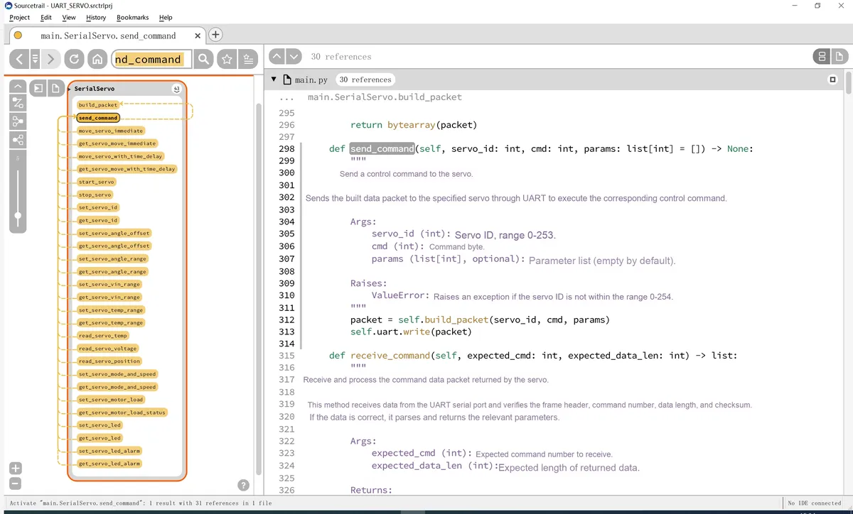
- Command Receiving Method
receive_command:receive_command ()is a method used to receive feedback data from the steering gear, and its working process is as follows:- Command Verification: Confirm that the received command is a read command rather than any other type of command.
- Data check: Verify whether the frame header of the data is correct, whether the command number matches, and whether the data length meets the expectation.
- Checksum Verification : Verify whether the checksum of the received data packet is correct to ensure that the data has not been tampered with.
- Data Parsing: Parse and return the status or data of the servo (such as voltage, angle, etc.) according to the length of the returned data.
- If the data packet is invalid (e. g., due to a checksum error, mismatched data length, etc.), this method will return an empty list.
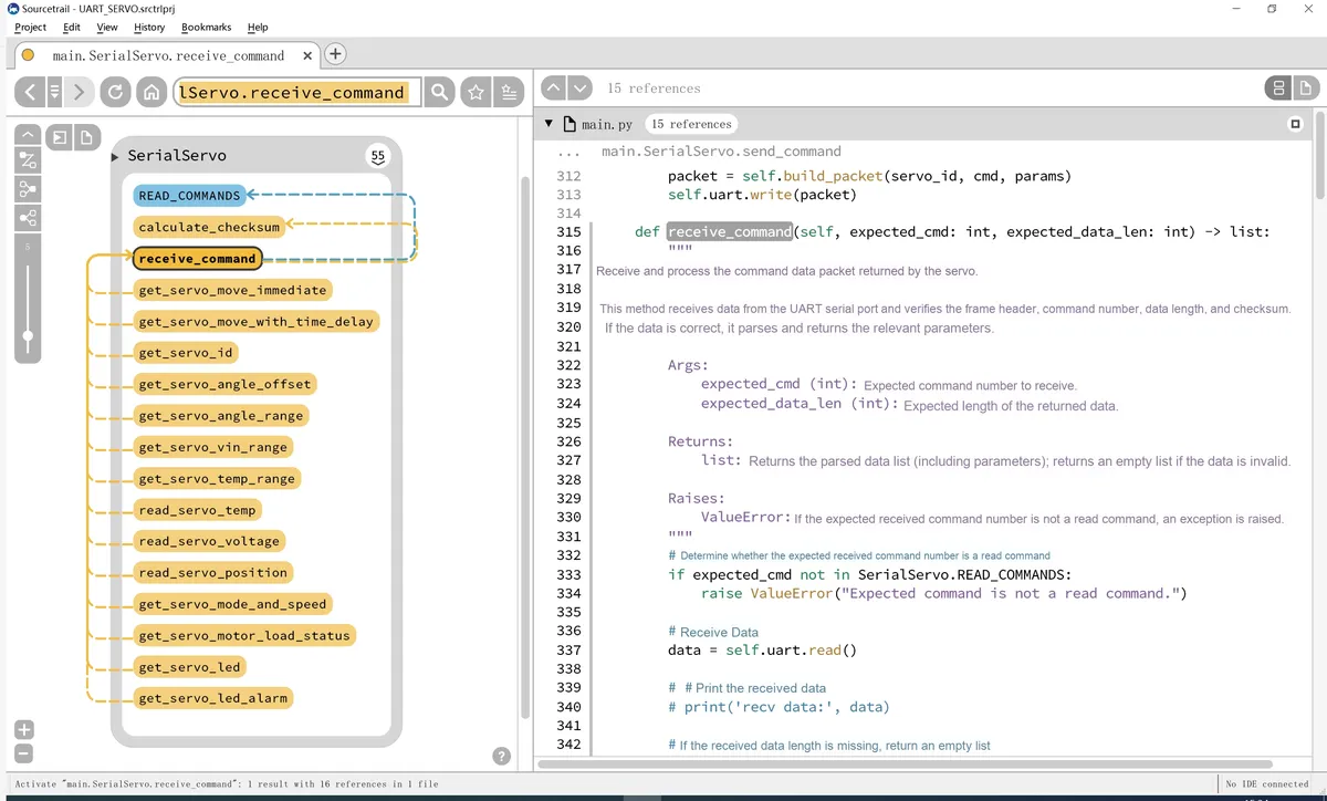
SerialServo class, all upper-layer functional methods (such as servo rotation, parameter configuration, status reading, etc.) are implemented based on three core communication modules: build_packet (packet assembly), send_command (transmission), and receive_command (reception and parsing).These three core methods constitute the "communication pipeline" of the driver. Essentially, the upper-layer methods are the "service-oriented encapsulation" of this pipeline — they convert the "physical quantities"(such as angle and voltage) input by the user into the "original parameters" required by the protocol, and then complete the interaction with the steering gear through the core module.
According to functional scenarios, upper-layer methods can be divided into "write operations that only send instructions" and "read-write operations that send first and then receive", and the two have different calling logics for the core module:
- Write operation methods: only call
send_command(includingbuild_packet), which are operations that do not require return data from the servo (such as controlling rotation, setting ID, starting and stopping the servo, etc.), with the core being "pack and send parameters". - Read-write operation methods: call
send_command+receive_command. For operations that require obtaining the status of the servo (such as reading temperature, position, angle deviation, etc.), the core logic is "send a read command first, then receive and parse the response".
For example the move_servo_immediate method, which is a write operation type method, the code is as follows:
    def move_servo_immediate(self, servo_id: int, angle: float, time_ms: int) -> None:
        """
        Immediately control the servo to rotate to the specified angle.

        This method uses the SERVO_MOVE_TIME_WRITE command to rotate the servo to the specified angle within the given time.

        Args:
            servo_id (int): Servo ID, range 0~253.
            angle (float): Target angle (within the range 0~240 degrees). Each unit represents 0.24 degrees.
            time_ms (int): Rotation time (0~30000 milliseconds), the time for the servo to rotate to the specified angle.

        Raises:
            ValueError: Raised if the angle is not within 0~240 degrees, the servo ID is not within 0~253, or the time is out of range.

        ===================================================

        Immediately control the servo to rotate to the specified angle.

        Args:
            servo_id (int): Servo ID, range 0~253.
            angle (float): Target angle (0~240 degrees). Each unit represents 0.24 degrees.
            time_ms (int): Time to rotate (0~30000 milliseconds), indicating the time for the servo to rotate to the specified angle.

        Raises:
            ValueError: If the angle is not in the range 0~240, the servo ID is not in the range 0~253,
            or the time is not in the range, an exception will be raised.

        """
        # Check whether the angle is within 0~240 degrees
        if angle < 0 or angle > 240:
            raise ValueError("Angle must be in range 0~240.")

        # Check whether the time is within 0~30000 milliseconds
        if time_ms < 0 or time_ms > 30000:
            raise ValueError("Time must be in range 0~30000.")

        # Convert the angle to the low byte and high byte required by the servo control command
        # Convert to an integer and limit to the low 8 bits
        angle_low = int(angle / 0.24) & 0xFF
        # Get the high 8 bits
        angle_high = (int(angle / 0.24) >> 8) & 0xFF

        # Convert the time to low byte and high byte
        # Convert to the low 8 bits
        time_low = time_ms & 0xFF
        # Get the high 8 bits
        time_high = (time_ms >> 8) & 0xFF

        # Send the SERVO_MOVE_TIME_WRITE command
        self.send_command(servo_id, SerialServo.SERVO_MOVE_TIME_WRITE[0], [angle_low, angle_high, time_low, time_high])
It does not require operations that rely on feedback data from the servo (such as controlling rotation, setting ID, starting/stopping the servo, etc.), and its core logic is "sending parameters in a packaged form": when a user inputs the servo ID, target angle and rotation duration, the move_servo_immediate method first performs validity check, then converts the target angle and rotation duration into the lower 8 bits and upper 8 bits required for the servo control command, and finally calls the send_command method (which internally invokes build_packet) to transmit the data.
For methods of the read-write operation type, the process is as follows:
- Send a read command (
send_command) - delay waiting
- Receive Response (
receive_command) - Parse parameters
- Physical Quantity Conversion
- Return Result
Taking the read_servo_position method as an example, which belongs to the read-write operation type methods, the code is as follows:
    def read_servo_position(self, servo_id: int) -> float:
        """
        Get the real-time angle position of the servo.

        This method sends the `SERVO_POS_READ` command by servo ID to read the servo's current angular position.
        The returned position value must be mapped from the range 0~1000 to the angle 0~240°.

        Args:
            servo_id (int): The servo ID.

        Returns:
            float: The servo's current angular position in degrees, range 0~240°.
                   Returns None if the read fails.

        Raises:
            ValueError: Raised if the angular position is not within 0~240 degrees.

        =======================================================

        Get the real-time position of the servo.

        This method sends the `SERVO_POS_READ` command using the servo's ID to read the current angle position of the servo.
        The returned position value needs to be mapped from the range 0~1000 to the angle range 0~240°.

        Args:
            servo_id (int): The servo's ID.

        Returns:
            float: The current angle position of the servo, in degrees, with a range of 0~240°.
                   If the read operation fails, it returns None.

        Raises:
            ValueError: If the position is not within the range of 0~240°, an exception will be raised.

        """
        # Send the SERVO_POS_READ command
        self.send_command(servo_id, SerialServo.SERVO_POS_READ[0], [])

        # Delay 5ms before receiving data
        time.sleep_ms(5)

        # Receive and parse the returned data
        params = self.receive_command(SerialServo.SERVO_POS_READ[0], SerialServo.SERVO_POS_READ[2])

        # If no data is received, return None
        if len(params) == 0:
            return None

        # Combine the low and high bytes of the angular position into a 16-bit integer
        position_value = params[0] + (params[1] << 8)

        # Convert the value to signed short int data (may be negative)
        # Check whether it is negative
        if position_value >= 0x8000:
            # If negative, perform two's complement conversion
            position_value -= 0x10000

        # Convert the position value to an angle, mapped to the 0~240° range
        position_angle = (position_value / 1000) * 240

        # Check whether the angle value is within a reasonable range
        if not (0 <= position_angle <= 240):
            raise ValueError("Position is out of range.")

        return position_angle
3.3.3.2 Experimental Preparations and Experimental Phenomena
Here, you can check it out on our blog:
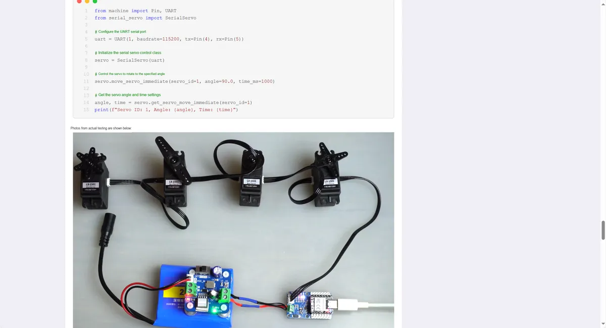
The address is: https://www.cnblogs.com/FreakEmbedded/p/18742422 .
3.4 Monitor serial port events using the select module
In the following experiment, we need to use a MiniUSB data cable to connect the Fengya No. 1 Board - Universal Compatible Expansion Board 's UART0 USB port to the USB port on a computer:
In serial communication, the workflow of using the select module to monitor the active status of the serial port is as follows:
- Create a serial port object: Use
machine.UARTto create a serial port object, and configure parameters such as baud rate, data bits, and parity bits. - Create
a pollobject: Useselect.poll ()to create apollobject for polling and registering serial port events. - Register Serial Port Device: Register the serial port device to the
pollobject, and monitor thePOLLINevent, which means that when there is data readable on the serial port, the polling mechanism will be triggered. - Polling serial port events: Use
poll.poll ()to perform polling and wait for I/O events of the serial port device. The polling method will block until there is data readable on the serial port or return after a timeout. - Processing serial port data: Once
poll ()returns an event, the program can useuart.read ()to read the serial port data for processing.
In the following code, we use the select module to monitor serial port events and read data, handle events such as serial port errors and device disconnection, and store the received data in a buffer. The code will also clear the buffer when it is full to ensure that no data overflow occurs.
The sample code is as follows, located in the folder of the supporting materials: elegance-devkit v1\Demo\10 UART_SelectRead:
# Python env   : MicroPython v1.23.0
# -*- coding: utf-8 -*-
# @Time    : 2024/6/27 12:08 AM
# @Author  : Li Qingshui
# @File    : main.py
# @Description : Select class experiment, mainly using the select module to read serial port status and receive data

# ======================================== Import Modules ========================================
# Hardware-related modules
from machine import UART, Pin
# Time-related modules
import time
# Import the select module
import select

# ======================================== Global Variables ============================================

# Create a serial data buffer
uart_buffer = []
# Maximum length of the serial data buffer
uart_buffer_max_len = 100

# ======================================== Functions ============================================

def handle_uart_error(event: int) -> None:
    """
    Handle the serial port error event.

    When a serial port error occurs, this method is called to handle it. It tries to reset the serial connection,
    and reinitializes the serial port settings to ensure communication returns to normal.

    Args:
        event (int): Event type identifier. This function is called only when the event type is `POLLERR`.
    """
    if event & select.POLLERR:
        print("UART error occurred, resetting UART")
        # Turn off the LED indicator on error
        LED.off()
        # Possible recovery operation: close the serial port, then reinitialize
        uart.deinit()
        # Wait 1 second, then reinitialize
        time.sleep(1)
        uart.init(bits=8, parity=None, stop=1, tx=0, rx=1, timeout=5)
        # Turn the LED back on to indicate recovery
        LED.on()

def handle_uart_disconnect(event: int) -> None:
    """
    Handle the serial port disconnect event.

    When the serial connection is disconnected, this method is called to handle it. It stops serial port operations and turns off the LED indicator,
    and prepares to reconnect the serial port.

    Args:
        event (int): Event type identifier. This function is called only when the event type is `POLLHUP`.
    """
    if event & select.POLLHUP:
        print("UART disconnected, resetting UART")
        # Turn off the LED on disconnect
        LED.off()
        # Stop serial port operations
        uart.deinit()
        # Wait 1 second, prepare to reconnect
        time.sleep(1)

# ======================================== Custom Classes ============================================

# ======================================== Initialization ==========================================

# Power-on delay of 3 s
time.sleep(3)
# Print debug message
print("FreakStudio: Using select module to read UART data")

# Create a serial port object, set the baud rate to 9600
uart: UART = UART(0, 9600)
# Initialize the uart object: 8 data bits, no parity bit, 1 stop bit
# Set the input pin to GPIO1 and the output pin to GPIO2
# GPIO1 and GPIO2 are shorted, UART 0 sends to and receives from itself
# Set the UART timeout to 5 ms
uart.init(bits=8,
          parity=None,
          stop=1,
          tx=0,
          rx=1,
          timeout=5)

# Set GPIO 25 as the LED output pin, pull-down resistor enabled
LED: Pin = Pin(25, Pin.OUT, Pin.PULL_DOWN)

# Create a poll object to monitor the serial port's activity status
uart_read_poll: select.poll = select.poll()
# Register the serial port object with the poll object
# select.POLLIN is a constant representing a readable event
# select.POLLERR is a constant representing an error event
# select.POLLHUP is a constant representing a device disconnect event
# When data is available to read on the serial device, the uart_read_poll object is triggered
uart_read_poll.register(uart, select.POLLIN | select.POLLERR | select.POLLHUP)

# ========================================  Main Program  ============================================

while True:

    # Turn on the LED
    LED.on()

    # Use the poll method of Python's select module to listen for serial port events
    # The poll method blocks and waits until data can be received on the serial port
    # Set the timeout to 50ms; if no event occurs within 50ms, it returns
    events = uart_read_poll.poll(50)

    # events is a list containing device objects, including the fd attribute and the events attribute
    print('events =', events)

    # If events occur, handle them
    if events:
        # Loop through the event list
        for event in events:
            # Print the device and event type of the event that occurred
            print(" fd attributes/the name of the device          : ",event[0])
            print(" events property/the trigger type of the event : ",event[1])

            # If an event occurs on the uart object, handle it
            if event[0] == uart:

                # Call the handle_uart_error method to handle the serial port error event
                handle_uart_error(event[1])

                # Call the handle_uart_disconnect method to handle the serial port disconnect event
                handle_uart_disconnect(event[1])

                # If the uart object has readable data, read and print the received data
                if event[1] & select.POLLIN:
                    # Try to read serial port data
                    try:
                        # Read one byte of serial port data
                        data = uart.read(1)
                        # Print the received data
                        print("uart recv data = ", data)
                        # Add the data to the buffer
                        uart_buffer.append(data)
                        # You can choose to process or analyze the received data here
                        # ...

                        # When the buffer is full, clear it
                        if len(uart_buffer) >= uart_buffer_max_len:
                            # Clear the buffer
                            uart_buffer.clear()

                        # Turn off the LED to indicate that data reading is complete
                        LED.off()
                    except Exception as e:
                        print("uart read error: ", e)
In the above code, we first use UART to create a serial port object and configure an LED.
Then a select.poll object uart_read_poll is created, which is used to monitor the active status of the serial port, including:
POLLIN: Readable event, indicating that there is data available to read from the serial port.POLLERR: Error event, indicating that an error has occurred in the serial port device.POLLERRevent means that some kind of error has occurred in the device (such as serial port line error or device driver error), which may result in the failure to perform normal data read or write operations.POLLHUP: Disconnection event, indicating that the serial port device has been disconnected (e. g., the serial port connection cable is unplugged, or the virtual serial port on the computer closes the connection). Note that in MicroPython for Raspberry Pi Pico, the serial port will not automatically send a disconnection notification when the serial device is disconnected, and the operating system itself does not actively detect the physical disconnection of the serial port; only when a USB-based virtual serial port device is disconnected, it may trigger aPOLLERRorPOLLHUPevent.
Next, we use the uart_read_poll.register method to register the serial port object with the poll object, so as to monitor these events;In the main loop, uart_read_poll.poll (50) is used to listen for serial port events. The poll method will block until an event is triggered, or return if no event occurs within 50 milliseconds. Here, events is a list containing device objects, and the elements in the list, namely event objects, are in the form of tuples:(fd attribute - device name, events attribute - event type).
If an event occurs, the program iterates through the events list and checks the device and event type for each entry:
- Error event (
POLLERR): If an error is detected on the serial port, thehandle_uart_errorfunction will be called to handle the error. This function will attempt to reset the serial port connection and reinitialize the serial port settings. - Disconnection event (
POLLHUP): If the serial port device disconnection is detected, call thehandle_uart_disconnectfunction to stop the serial port operation and prepare for reconnection. - Readable event (
POLLIN): If there is data available to read on the serial port, the system will attempt to read one byte of data and add it to the buffer. The received data will be printed out.
Meanwhile, the received data will be stored in a list named uart_buffer. To prevent buffer overflow, a maximum length uart_buffer_max_len is set, and the buffer will be cleared once the data volume in it exceeds this maximum value.
At each stage of the program, LEDs serve as indicator lights to show the system status:
- If the event is processed (e. g., data is read),
the LEDwill light up. - After data processing is completed,
the LEDwill turn off, indicating that data reading is finished.
Next, we flash the program to the Raspberry Pi Pico, open the terminal, and send data via the XCOM serial port assistant. The operation is as follows:
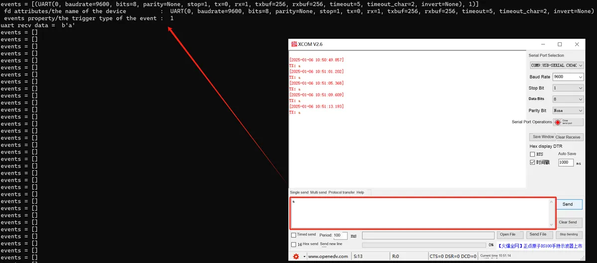
3.4 Application Experiment.mp4 10.8 MB
When serial port data is received, the terminal outputs the following:
events = [(UART(0, baudrate=9600, bits=8, parity=None, stop=1, tx=0, rx=1, txbuf=256, rxbuf=256, timeout=5, timeout_char=2, invert=None), 1)]
fd attributes/the name of the device          :  UART(0, baudrate=9600, bits=8, parity=None, stop=1, tx=0, rx=1, txbuf=256, rxbuf=256, timeout=5, timeout_char=2, invert=None)
events property/the trigger type of the event :  1
uart recv data =  b'a'
outputs the event list (events), device name, event type, and the data received via the serial port (uart recv data = b'a').
When multiple stream devices are performing data receiving operations (for example, three serial ports are all connected to external sensors), using the select module for event monitoring can help us correctly complete data reception and further processing whenever data is available on any of the serial ports.
Stream Devices and Block Devices
The concepts of stream devices and block devices were primarily introduced in the Linux system, where devices are categorized into two types: stream devices and block devices. Stream devices refer to devices that read and write data in the ByteFlow mode, such as tape drives, serial ports, and pipes. Block devices, on the other hand, are devices that read and write data in data block units, including hard disks and USB flash drives. In practical applications, we need to select the appropriate type of device based on specific requirements to achieve efficient data transmission.
Stream devices and block devices each have their own characteristics and application scenarios:
- Streaming Device:
Stream devices are devices that read and write data in ByteFlow mode. Their read and write operations do not support seeking, which means that data can generally only be read sequentially on a stream device. Therefore, stream devices are often used in scenarios requiring high-speed data transmission, such as network communication, Data Acquisition, etc. In addition, stream devices are also frequently used for Inter-Process Communication, such as pipes and sockets.
In Linux systems, read and write operations for stream devices are completed via file descriptors. Each stream device is treated as a file, which can be opened with the open system call to obtain a file descriptor; thereafter, system calls such as read and write can be used to perform data read and write operations.
In practical applications, we need to pay attention to the data caching issue of stream devices. The read and write operations of stream devices directly read data from or write data to the device, so data caching is of great importance. For example, when performing network communication, we need to take into account the sliding window of the TCP protocol, which is essentially a data buffer. Therefore, to achieve efficient data transmission, we need to organize data buffers reasonably to reduce the number of read and write operations.
- Block device:
Block devices are devices that read and write data in blocks. Their read and write operations usually support seeking, which means we can read and write any data block on the device arbitrarily. Therefore, block devices are often used in scenarios that require storing large amounts of data, such as hard disks, USB flash drives, etc.
In Linux systems, block devices are also treated as files and can be mounted into the file system. We can use block devices to create file systems and store data in them. When an application needs to read or write a file, the system maps the physical address and logical address of the file to implement data read and write operations.
Unlike stream devices, block devices generally support caching. In the Linux kernel, there is a mechanism called page cache, which can cache data blocks on the disk into memory and perform read and write operations when needed. The size of the page cache is usually 4KB or 8KB, so we need to make appropriate adjustments according to the actual situation.
file descriptor
In Linux, everything is a file. A file descriptor is an index created by the kernel to efficiently manage opened files; it is a non-negative integer used to refer to an opened file, and all system calls that perform I/O operations (accessing and manipulating specified files) are completed via file descriptors.
In Linux, processes access files via file descriptors (abbreviated as fd), which are essentially integers. When a program first starts up, it has three default file descriptors: 0 (representing standard input), 1 (representing standard output), and 2 (representing standard error). If a new file is opened subsequently, its file descriptor will be 3.
3.5 RS232 Communication
3.5.1 Fundamentals of RS232 Communication
RS-232 is a widely used serial Communication Protocol, originally defined by the Electronic Industries Association (EIA) in the 1960s, which is used for data transmission between computers and external devices such as modems, printers, sensors, etc.
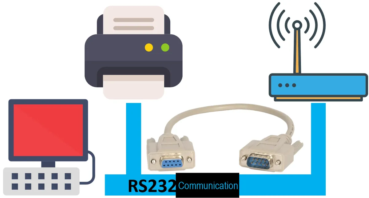
As we mentioned earlier when discussing the serial port Communication Protocol layer, the RS-232 standard and the TTL electrical standard we use in serial communication only differ in the logic level standards they adopt, while they are identical in terms of the specific serial port protocol, including the packet structure of serial communication, error detection and correction, as well as rate matching and synchronization:
- RS-232: It uses high-level and low-level signals. The standard defines the high level as + 3V to + 25V and the low level as -3V to -25V. Due to its relatively high signal level, RS-232 is suitable for long-distance transmission.
- TTL-UART: Uses TTL logic levels, where the high level typically ranges from + 2.5V to + 5V (commonly 5V) and the low level is 0V; TTL signal levels are suitable for short-distance communication.
3.5.2 Introduction to MAX3232 Chip
Here, we use the MAX3232 chip to convert TTL levels (0V to + 5V) to RS-232 standard levels (±3V to ±25V). The MAX3232 is a commonly used RS-232-to-TTL (or CMOS) level converter chip that supports a data transmission rate of up to 250kbps and dual-channel RS-232-to-TTL (or CMOS) level conversion, and is often used for serial communication between microcontrollers and devices such as computers, modems, and printers.
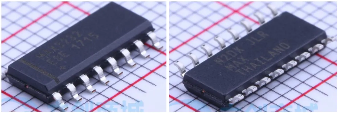
The pin names and functions of the MAX3232 chip are as follows:
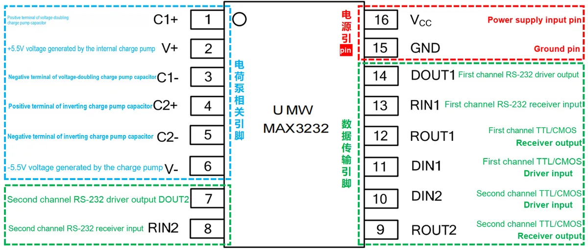
They are divided into the following three categories according to their functions:
- Charge Pump Related Pins: These pins are used for the operation of the internal charge pump, which generates the required voltages (+ 5.5V and -5.5V) via external capacitors to provide appropriate levels for the RS-232 driver.
- Power and Ground Pins: Supply power and ground for the MAX3232 to ensure normal operation of the chip, with a supply voltage range of + 3.0V to + 5.5V.
- Data transmission pin: Used for level conversion between TTL/CMOS and RS-232, including RS-232 receiver input and output as well as TTL/CMOS driver input and output.
Its working principle can be briefly summarized as follows: the MAX3232 converts the input low voltage (e. g., 3.3V or 5V) into high voltages that comply with the RS-232 standard (typically + 5V to + 15V and -5V to -15V) via its built-in charge pump circuit and inverters.
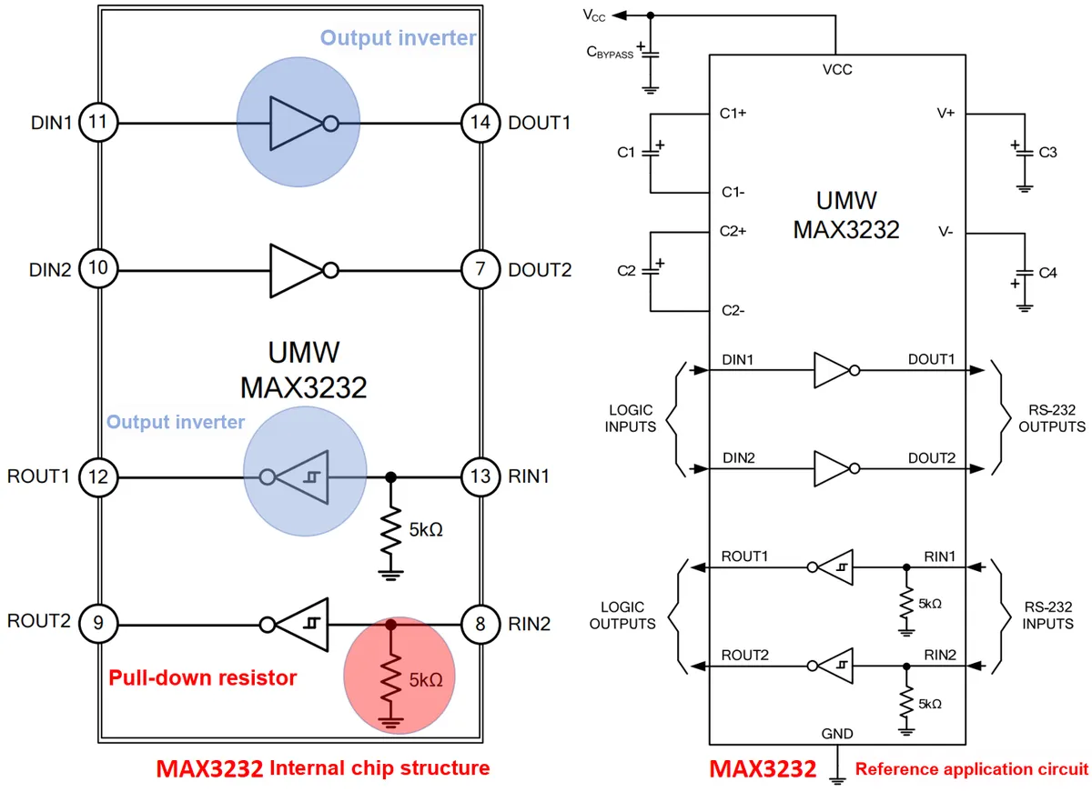
Here, the capacitance value required for the operation of the internal charge pump corresponds to a magnitude that is related to the supply voltage:

RS-232 communication often uses DB9 connectors, which have 9 pins, each with a specific function in RS-232 communication. The pin numbers and corresponding functions are as follows:
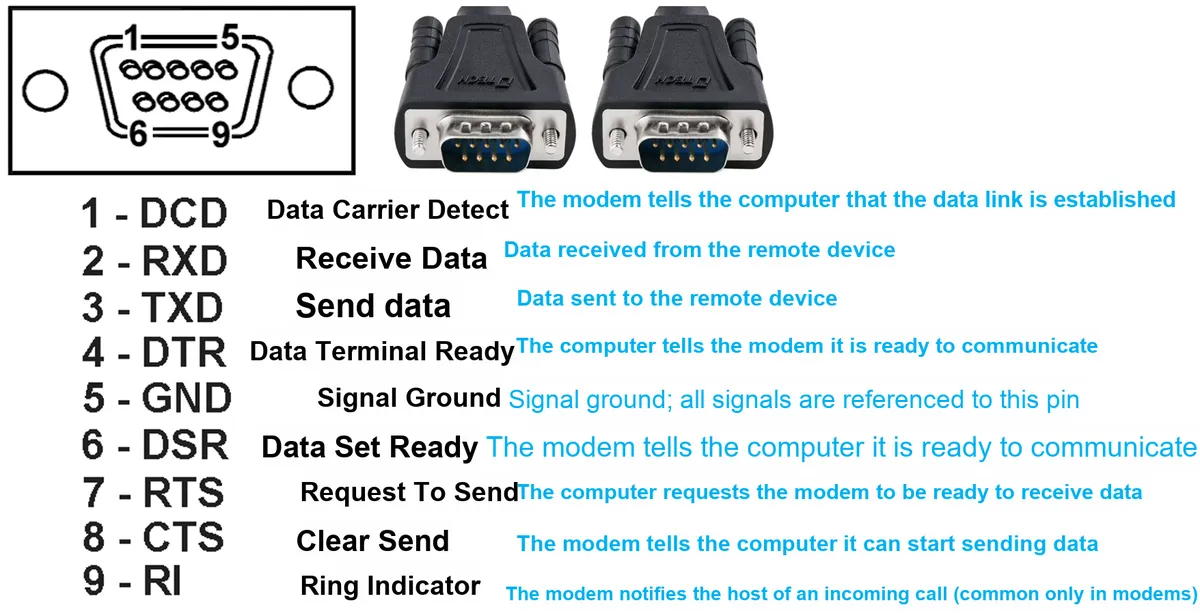
Here, we only use the pins RXD, TXD and GND of the DB9 interface.
There are two types of DB9 connectors: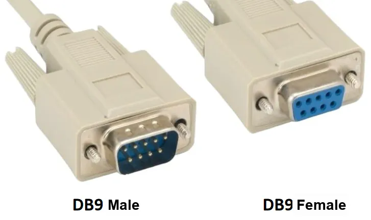
- Male connector: features 9 protruding metal pins
- Female connector: It has 9 small holes for receiving the pins of the male connector
3.5.3 USB to RS232 Adapter
Typically, the serial port of a computer or device adopts a DB9 female connector, while one end of a serial cable is a DB9 male connector; the DB9 connector used on our development board is a female type. On current computers, DB9 connectors have long been phased out, but virtual serial ports (implemented via USB-to-serial conversion) remain functional, and we can use a USB-to-DB9 adapter to enable communication between a microcontroller and a computer over the RS232 protocol.
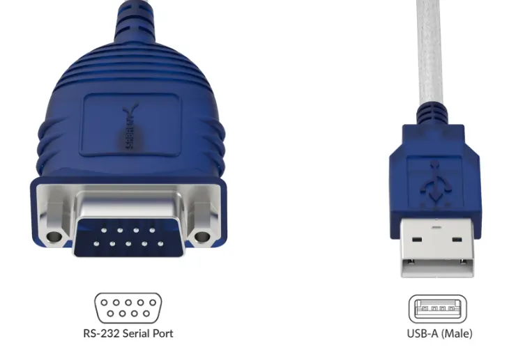
Here, USB-to-RS232 adapters often use a built-in FT232 chip to implement the conversion between different Communication Protocols. The FT232 is a USB-to-serial chip designed by FTDI, which is widely used in embedded systems, microcontroller development and debugging, as well as converting traditional RS-232 or TTL serial interfaces to USB interfaces, enabling modern devices to communicate with legacy serial devices.
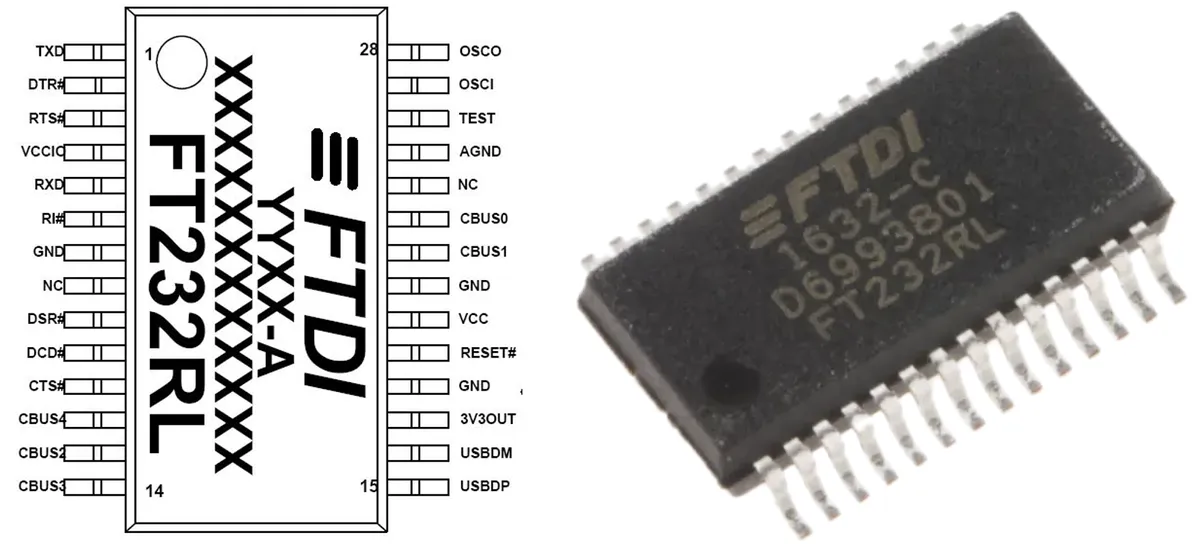
The FT232 chip requires the driver provided by FTDI to be installed in most operating systems, which can be downloaded from FTDI's official website specifically:
https://ftdichip.com/drivers/vcp-drivers/
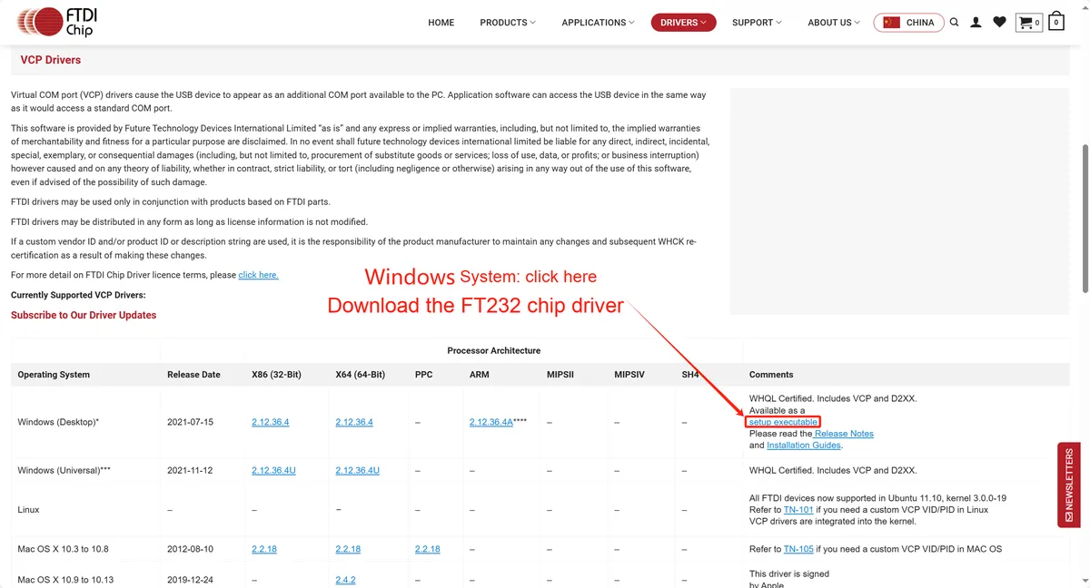
Here, the USB-to-RS232 adapter we provide adopts a domestically produced MS3020 chip, for which the corresponding driver also needs to be installed. If you directly connect the USB-to-RS232 adapter to a computer without installing the matching driver, normal communication will not be possible; the display in Device Manager will be as follows:
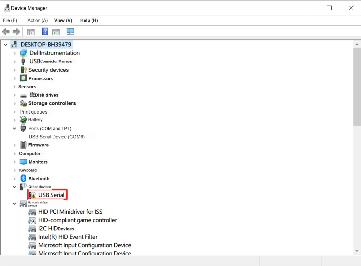
The driver download link is as follows:
http://www.dtech.cn/download/download.php?class3=410
You can also find the corresponding driver in the utility software we provide:

Open the PDF file of the driver installation instructions and follow the steps to complete the installation:

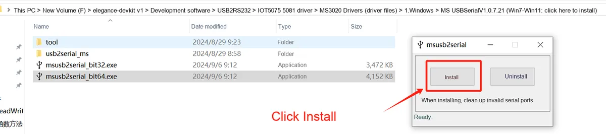
After the installation is successful, click Device Manager again, and you will find that the small exclamation mark on the original device has disappeared and the device can be used normally; you can also select its port normally in the corresponding serial communication software assistant:
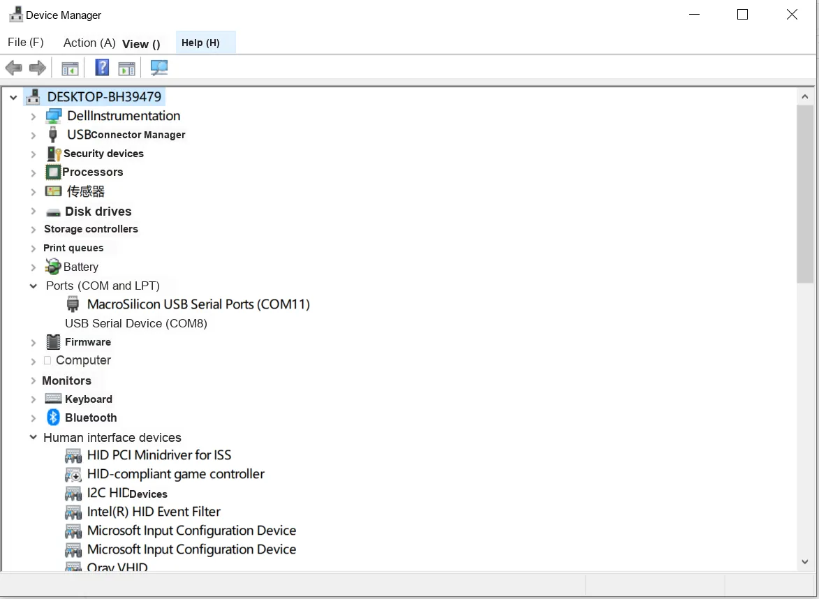
3.5.4 Application Experiment
In the following code, we use a custom RS232 data transceiver class to implement point-to-point communication between the master device (Raspberry Pi Pico) and the slave device (computer), and implement in the custom class software flow control (Software Flow Control) function. The so-called software flow control, also known as XON/XOFF flow control, is a software-based serial communication flow control mechanism. It uses specific control characters to start or stop data transmission. These control characters are sent through the serial communication line, no additional physical connection is required, and it completely relies on the serial data line.
Software flow control typically uses the following two ASCII control characters:
- XON (0x11, CTRL-Q): indicates "resume data transmission"(the sender may continue transmitting)
- XOFF (0x13, CTRL-S): indicates "suspend data transmission"(the sender shall pause transmission to avoid buffer overflow at the receiver end)
So when should these two ASCII control characters be used? Let’s briefly explain their application scenarios below:
- The receiver sends XOFF: When the receiver's buffer is nearly full, the receiver sends an XOFF signal to notify the sender to suspend data transmission
- Sender Pauses Transmission: Upon receiving the XOFF signal, the sender immediately pauses data transmission and waits for further instructions.
- The receiver sends XON: When the receiver has finished processing the data and frees up buffer space, it will send an XON signal to inform the sender that it can resume transmitting data
- The sender continues transmission: After receiving the XON signal, the sender resumes data transmission until it receives an XOFF signal again or completes data transmission
In the following experiment, we need to insert the Fengya No. 1 Board - Grove Interface expansion board into the Fengya No. 1 Board - Serial Port Level Conversion Board, and at the same time turn on the RS232-SW DIP switch RS232-TXD and RS232-RXD options. We use the serial peripheral 0 to connect to the TTL1 interface of the RS232 chip on the Fengya No. 1 Board - Serial Port Level Conversion Board , set the receive pin of the Raspberry Pi Pico to GPIO17, and the transmit pin to GPIO16:
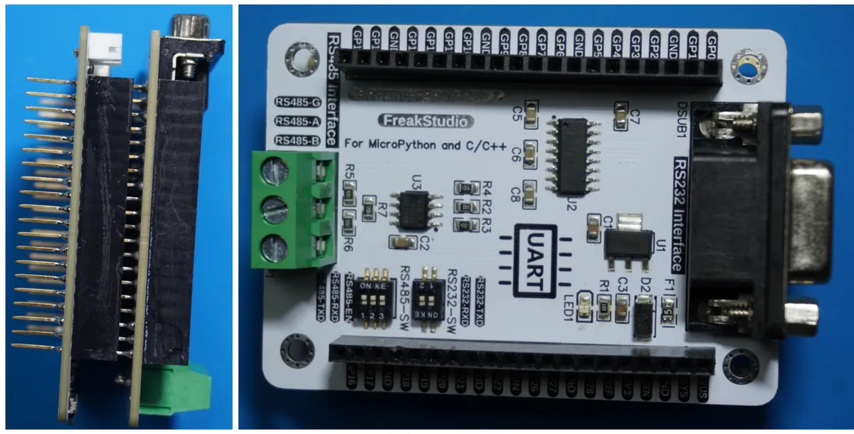
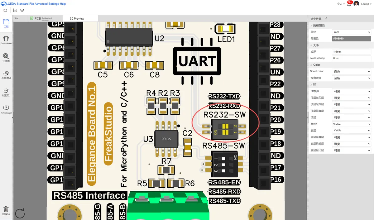
Next, we use a USB-to-RS232 adapter to connect to Fengya No. 1 Board - Serial Port Level Conversion Board ’s RS232 Interface port, and the physical connection diagram is shown as follows:
First, we customize an RS232 communication class with software flow control function, and the sample code is as follows:
# Custom RS232 serial communication class, using software flow control
class RS232:
    """
    Custom RS232 serial communication class, supporting software flow control (XON/XOFF protocol).

    This class implements the sending and receiving functions of the RS232 serial port, and supports XON/XOFF-based flow control. Flow control is used during data transmission to
    control the sending and pausing of data according to the state of the receive buffer, preventing receive buffer overflow. Through this class, serial data sending, receiving, and flow control management can be performed.

    Attributes:
        uart (UART): Serial port instance, representing the hardware interface used for communication.
        tx_buffer (bytearray): Transmit buffer, used to store data to be sent.
        rx_buffer (bytearray): Receive buffer, used to store received data.
        rx_pos (int): Receive buffer pointer, marking the position of the received data.
        rx_buf_size (int): Receive buffer size, the maximum amount of data the receive buffer can store.
        tx_pos (int): Transmit buffer pointer, marking the position of the data that is ready to be sent.
        tx_buf_size (int): Transmit buffer size, the maximum amount of data the transmit buffer can store.
        xon (bool): Software flow control state, indicating whether data can currently be sent. `True` means sending is allowed, `False` means sending must pause.

    Methods:
        send(data: str) -> None:
            Send data to the serial port. Supports XON/XOFF flow control; if flow control is in the paused state during sending, it waits until the XON signal is restored.

        receive() -> bytearray:
            Receive data from the serial port. If the receive buffer is full during reception, an XOFF signal is sent to pause data transmission.
    """

    # Software flow control related class variables: two ASCII control characters
    # XON (CTRL-Q)
    XON = b'\x11'
    # XOFF (CTRL-S)
    XOFF = b'\x13'

    def __init__(self, uart, rx_buf_size=256, tx_buf_size=256):
        """
        Initialize the serial port object.

        Args:
            uart (UART): The UART instance to use.
            rx_buf_size (int, optional): Size of the receive buffer. Default is 256.
            tx_buf_size (int, optional): Size of the transmit buffer. Default is 256.

        Returns:
            None
        """

        # Save the passed-in UART object
        self.uart = uart
        # Transmit buffer, stores data waiting to be sent
        self.tx_buffer = bytearray(tx_buf_size)
        # Receive buffer, stores received data
        self.rx_buffer = bytearray(rx_buf_size)

        # Receive buffer pointer, tracks the data position
        self.rx_pos = 0
        # Receive buffer size
        self.rx_buf_size = rx_buf_size

        # Transmit buffer pointer, tracks the data position
        self.tx_pos = 0
        # Transmit buffer size
        self.tx_buf_size = tx_buf_size

        # XON state, indicates data can be sent
        self.xon = True

    def send(self, data : str) -> None:
        """
        Send data.

        This function sends the given data to the serial port, following the XON/XOFF flow control mechanism. If flow control does not currently allow
        sending data, the function waits until flow control is released.

        Args:
            data (str): The data string to send.

        Returns:
            None
        """

        # If data is not a string, convert it
        if not isinstance(data, str):
            data = str(data)

        # If the data length exceeds the transmit buffer size, truncate it
        if len(data) > self.tx_buf_size:
            data = data[0:self.tx_buf_size]

        # Add the data to be sent to the transmit buffer
        # Insert the data at the current transmit buffer pointer self.tx_pos
        self.tx_buffer[self.tx_pos:self.tx_pos+len(data)] = data.encode('utf-8')
        # Update the transmit buffer pointer
        self.tx_pos += len(data)

        # Iterate over the data in the transmit buffer
        for i in range(self.tx_pos):

            # If XOFF is active, wait for the XON signal to continue transmission
            while not self.xon:
                time.sleep(0.01)  # Wait 10 milliseconds

            # Send a single byte, ensuring it is of bytes type
            self.uart.write(bytes([self.tx_buffer[i]]))

        # After sending, clear the transmit buffer by resetting the pointer
        self.tx_pos = 0

    def receive(self) -> bytearray:
        """
        Receive data.

        This function checks the serial port receive buffer, reads the received data and returns it. If the receive buffer is full,
        it signals the sender to pause transmission with XOFF.

        Returns:
            bytearray: The received data, returned as a byte array.
        """

        # Loop and check whether the UART receive buffer has data
        while uart.any():

            # Receive data byte by byte
            byte = self.uart.read(1)

            # Check whether it is an XON or XOFF signal
            if byte == RS232.XON:
                # XON received, transmission is allowed to continue
                self.xon = True
            elif byte == RS232.XOFF:
                # XOFF received, pause transmission
                self.xon = False
            else:
                # Store the received actual data in the receive buffer
                self.rx_buffer[self.rx_pos] = byte[0]
                # Move the buffer pointer
                self.rx_pos += 1

                # Buffer is full, send XOFF signal
                if self.rx_pos >= self.rx_buf_size:
                    self.uart.write(RS232.XOFF)
                    break
        # Slice the data
        data = self.rx_buffer[0:self.rx_pos]
        # Reset the receive buffer pointer
        self.rx_pos = 0
        # Return the received data
        return data
Custom RS232 class works as follows:
- Sending data
send (): First, check whetherdatais a string; if not, convert it to a string, encode the data into a UTF-8 byte string, and store it in the send buffertx_buffer; then send the data byte by byte. Before each data transmission, check thexonstatus. IfxonisFalse(i. e., an XOFF signal has been received), pause transmission until an XON signal is received; after the data is sent, reset the send buffer pointertx_posto 0 - Receive data
receive (): Check whether there is received data viaself.uart.any ()and read the data one by one; then perform XON/XOFF signal detection and received data storage. If the receive buffer is full (i. e.rx_posis equal to or greater thanrx_buf_size), send anXOFFsignal to the sender to notify it to suspend data transmission, finally return all received data, and reset the receive buffer pointerrx_pos
The complete code is shown below, located in the folder of the supporting materials: elegance-devkit v1\Demo\11 UART_RS232:
# Python env   : MicroPython v1.23.0
# -*- coding: utf-8 -*-
# @Time    : 2024/9/22 11:23 PM
# @Author  : Li Qingshui
# @File    : main.py
# @Description : UART class experiment, implementing software flow control over RS232 serial communication

# ======================================== Import Modules =========================================

# Hardware-related modules
from machine import UART, Pin, Timer
# Time-related modules
import time

# ======================================== Global Variables ============================================

# Serial transmit counter variable
send_count: int = 0

# ======================================== Functions ============================================

# Timer callback function, used to receive data periodically
def receive_data(timer: Timer) -> None:
    """
    Timer callback function, used to receive data periodically.

    This function checks the data received on the serial port and turns the LED on or off according to the flow control state.
    If the flow control signal allows sending data, the LED turns off; if the flow control signal forbids sending data, the LED turns on.

    Args:
        timer (Timer): The timer instance.

    Returns:
        None
    """
    global rs232,LED

    # Receive data
    data: bytearray = rs232.receive()

    # Check whether data was received
    if len(data) > 0:
        # Convert the received data to hexadecimal and print it
        hex_data = [hex(byte) for byte in data]
        print("Received data:", hex_data)

    # Check the RS232 flow control state
    if rs232.xon:
        # If data can be sent, turn off the LED
        LED.value(0)
    else:
        # If data cannot be sent, turn on the LED
        LED.value(1)

# ======================================== Custom Classes ============================================

# Custom RS232 serial communication class, using software flow control
class RS232:
    """
    Custom RS232 serial communication class, supporting software flow control (XON/XOFF protocol).

    This class implements the sending and receiving functions of the RS232 serial port, and supports XON/XOFF-based flow control. Flow control is used during data transmission to
    control the sending and pausing of data according to the state of the receive buffer, preventing receive buffer overflow. Through this class, serial data sending, receiving, and flow control management can be performed.

    Attributes:
        uart (UART): Serial port instance, representing the hardware interface used for communication.
        tx_buffer (bytearray): Transmit buffer, used to store data to be sent.
        rx_buffer (bytearray): Receive buffer, used to store received data.
        rx_pos (int): Receive buffer pointer, marking the position of the received data.
        rx_buf_size (int): Receive buffer size, the maximum amount of data the receive buffer can store.
        tx_pos (int): Transmit buffer pointer, marking the position of the data that is ready to be sent.
        tx_buf_size (int): Transmit buffer size, the maximum amount of data the transmit buffer can store.
        xon (bool): Software flow control state, indicating whether data can currently be sent. `True` means sending is allowed, `False` means sending must pause.

    Methods:
        send(data: str) -> None:
            Send data to the serial port. Supports XON/XOFF flow control; if flow control is in the paused state during sending, it waits until the XON signal is restored.

        receive() -> bytearray:
            Receive data from the serial port. If the receive buffer is full during reception, an XOFF signal is sent to pause data transmission.
    """

    # Software flow control related class variables: two ASCII control characters
    # XON (CTRL-Q)
    XON = b'\x11'
    # XOFF (CTRL-S)
    XOFF = b'\x13'

    def __init__(self, uart, rx_buf_size=256, tx_buf_size=256):
        """
        Initialize the serial port object.

        Args:
            uart (UART): The UART instance to use.
            rx_buf_size (int, optional): Size of the receive buffer. Default is 256.
            tx_buf_size (int, optional): Size of the transmit buffer. Default is 256.

        Returns:
            None
        """

        # Save the passed-in UART object
        self.uart = uart
        # Transmit buffer, stores data waiting to be sent
        self.tx_buffer = bytearray(tx_buf_size)
        # Receive buffer, stores received data
        self.rx_buffer = bytearray(rx_buf_size)

        # Receive buffer pointer, tracks the data position
        self.rx_pos = 0
        # Receive buffer size
        self.rx_buf_size = rx_buf_size

        # Transmit buffer pointer, tracks the data position
        self.tx_pos = 0
        # Transmit buffer size
        self.tx_buf_size = tx_buf_size

        # XON state, indicates data can be sent
        self.xon = True

    def send(self, data : str) -> None:
        """
        Send data.

        This function sends the given data to the serial port, following the XON/XOFF flow control mechanism. If flow control does not currently allow
        sending data, the function waits until flow control is released.

        Args:
            data (str): The data string to send.

        Returns:
            None
        """

        # If data is not a string, convert it
        if not isinstance(data, str):
            data = str(data)

        # If the data length exceeds the transmit buffer size, truncate it
        if len(data) > self.tx_buf_size:
            data = data[0:self.tx_buf_size]

        # Add the data to be sent to the transmit buffer
        # Insert the data at the current transmit buffer pointer self.tx_pos
        self.tx_buffer[self.tx_pos:self.tx_pos+len(data)] = data.encode('utf-8')
        # Update the transmit buffer pointer
        self.tx_pos += len(data)

        # Iterate over the data in the transmit buffer
        for i in range(self.tx_pos):

            # If XOFF is active, wait for the XON signal to continue transmission
            while not self.xon:
                time.sleep(0.01)  # Wait 10 milliseconds

            # Send a single byte, ensuring it is of bytes type
            self.uart.write(bytes([self.tx_buffer[i]]))

        # After sending, clear the transmit buffer by resetting the pointer
        self.tx_pos = 0

    def receive(self) -> bytearray:
        """
        Receive data.

        This function checks the serial port receive buffer, reads the received data and returns it. If the receive buffer is full,
        it signals the sender to pause transmission with XOFF.

        Returns:
            bytearray: The received data, returned as a byte array.
        """

        # Loop and check whether the UART receive buffer has data
        while uart.any():

            # Receive data byte by byte
            byte = self.uart.read(1)

            # Check whether it is an XON or XOFF signal
            if byte == RS232.XON:
                # XON received, transmission is allowed to continue
                self.xon = True
            elif byte == RS232.XOFF:
                # XOFF received, pause transmission
                self.xon = False
            else:
                # Store the received actual data in the receive buffer
                self.rx_buffer[self.rx_pos] = byte[0]
                # Move the buffer pointer
                self.rx_pos += 1

                # Buffer is full, send XOFF signal
                if self.rx_pos >= self.rx_buf_size:
                    self.uart.write(RS232.XOFF)
                    break
        # Slice the data
        data = self.rx_buffer[0:self.rx_pos]
        # Reset the receive buffer pointer
        self.rx_pos = 0
        # Return the received data
        return data

# ======================================== Initialization ==========================================

# Power-on delay of 3 s
time.sleep(3)
# Print debug message
print("FreakStudio: RS232 Software Flow Control Demo")

# Create the serial port object, set the baud rate to 115200
uart: UART = UART(0, 115200)
# Initialize the uart object with a baud rate of 115200, 8 data bits, no parity bit, and 1 stop bit
# Set the receive pin to GPIO17 and the transmit pin to GPIO16
# Set the serial port timeout to 100ms
uart.init(baudrate  = 115200,
          bits      = 8,
          parity    = None,
          stop      = 1,
          tx        = 16,
          rx        = 17,
          timeout   = 100)

# Initialize the RS232 object, set the receive buffer size to 32 and the transmit buffer size to 32
rs232: RS232 = RS232(uart, 32, 32)

# Set GPIO 25 as the LED output pin, pull-down resistor enabled
LED: Pin = Pin(25, Pin.OUT, Pin.PULL_DOWN)

# Create a timer object that receives data every 10ms
timer: Timer = Timer(-1)
timer.init(period=10, mode=Timer.PERIODIC, callback=receive_data)

# ========================================  Main Program  ===========================================

# Run in a loop
while True:
    # Send fixed data, with a newline after each transmission
    rs232.send("RS232 Send Data :" + str(send_count)+'\r\n')
    # Increment the transmit counter variable
    send_count = send_count + 1
    # Delay 1s
    time.sleep(1)
Here, in the main loop, we use the data transmission method in the custom class to send data approximately every 1 second. The timer checks for incoming data every 10 milliseconds; if any data is received, it will be printed to the terminal, and the flow control status of the current serial port will be indicated via the LED.
Here, the timer can be simply understood as an execution flow that periodically executes the corresponding callback function receive_data; it is triggered periodically, will call a certain function at regular set intervals and is not affected by the time.sleep delay method. In this program, through the periodic invocation of the timer, we can achieve continuous monitoring of serial port data.
Burn the code, open the terminal, and the following content will be displayed:
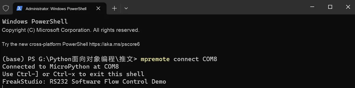
Open the serial port assistant and set the baud rate to 115200, keep other parameters as default, then select the COM port corresponding to the following name:
MacroSilicon USB Serial Ports
Here, when using the serial port assistant for communication, please note that the display should be in character format, the data should be sent in hexadecimal format, and do not select the "Send New Line" option.
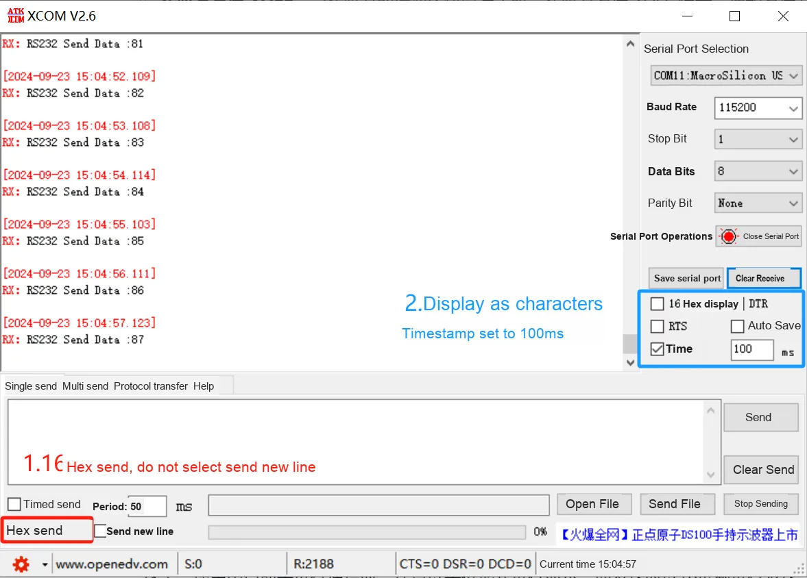
It can be seen that the custom RS232 communication class sends data at a timer interval of 1 second. Let's try sending hexadecimal data:
13 22 75 85 65 21 32
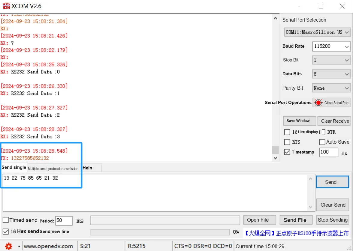
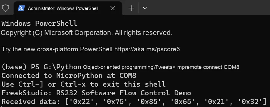
It can be seen that on the terminal, all data except the flow control character XOFF (0x13) is displayed. Meanwhile, on the serial port assistant software, you can observe that the Raspberry Pi Pico stops sending data, and the onboard LED on the Raspberry Pi Pico lights up:
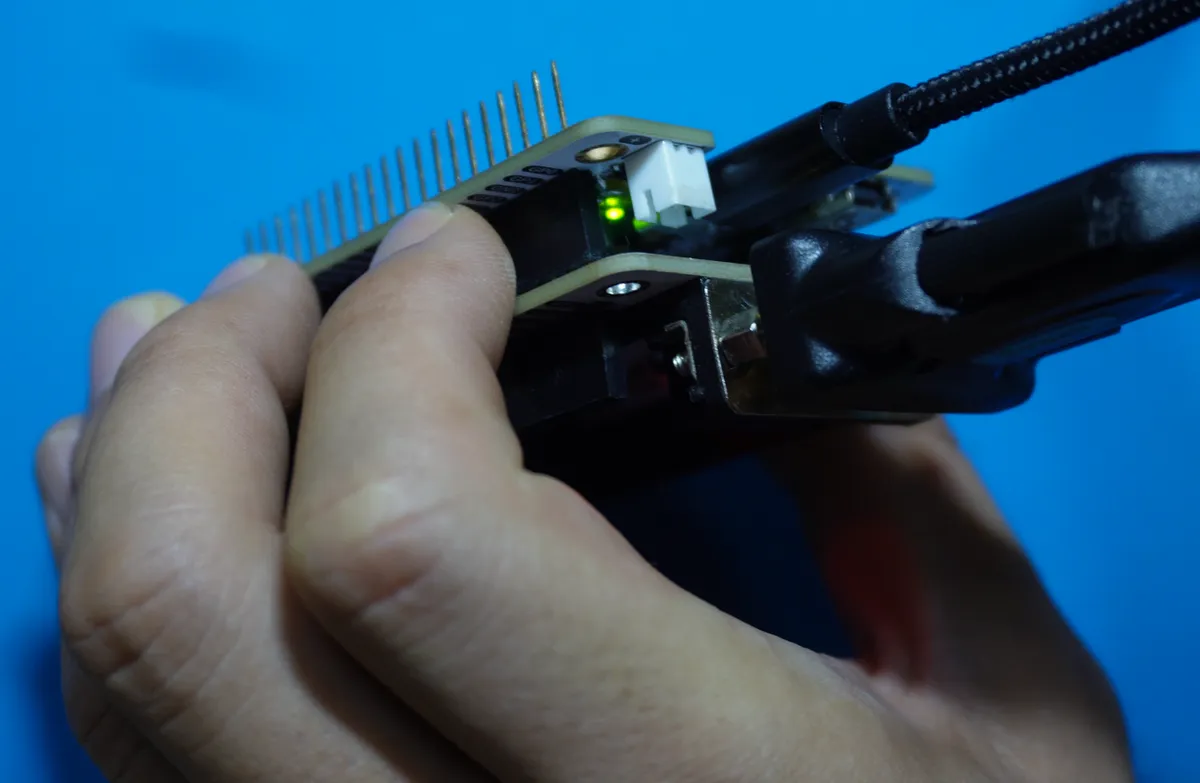
Resend data: 11 22 33 44 55 66, in which XON (0x11) flow control character indicates that the PC side is ready to receive data:
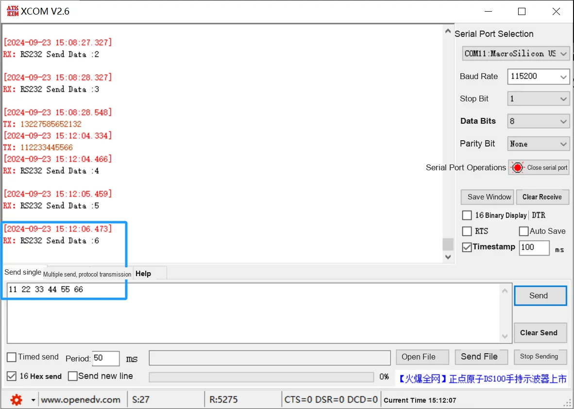
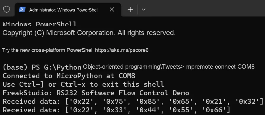
It can be found that at this point, the RS232 communication of the Raspberry Pi Pico restarts, and the on-board LED turns off at the same time:
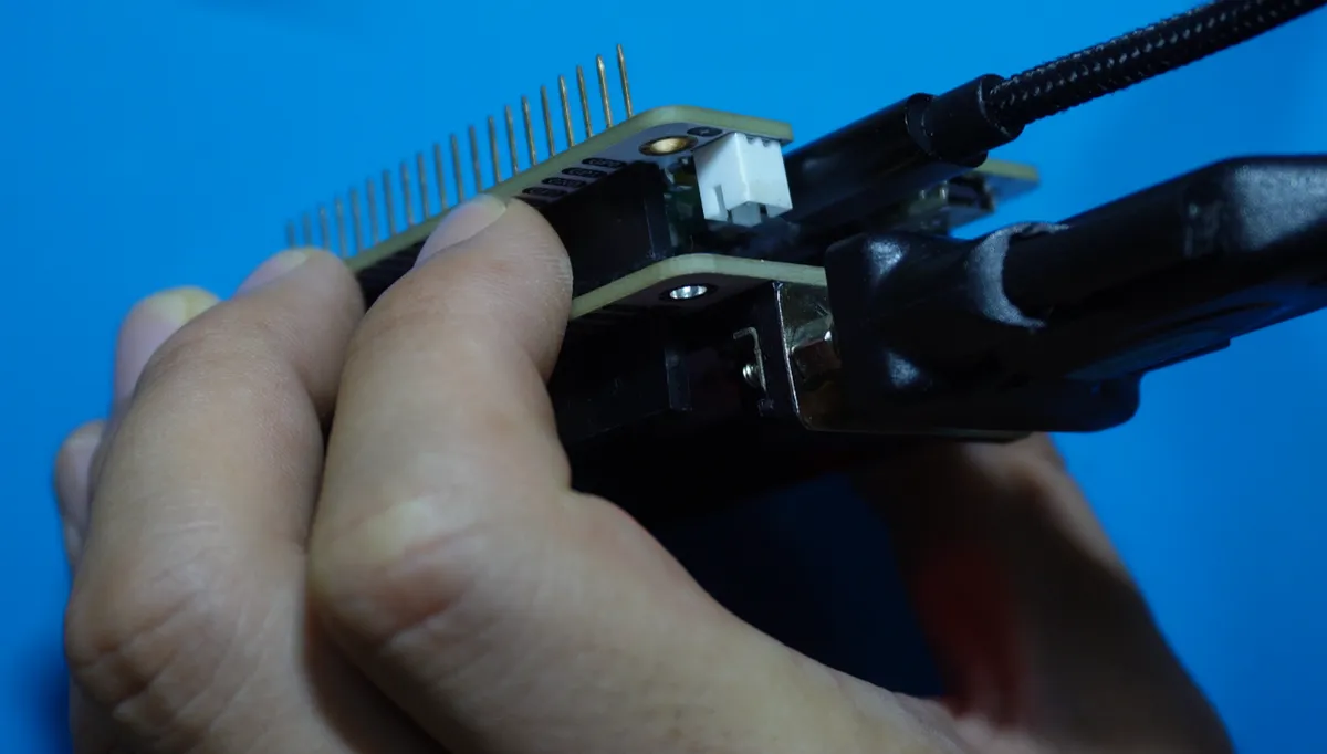
Here, we send a hexadecimal data whose length exceeds the set data buffer:
11 22 33 44 55 66 77 88 99 00 11 22 33 44 55 66 77 88 99 00 11 22 33 44 55 66 77 88 99 00 11 22 33 44 55 66 77 88 99 00 11 22 33 44 55 66 77 88 99 00 11 22 33 44 55 66 77 88 99 00And set in advance that the serial port assistant displays in hexadecimal mode:
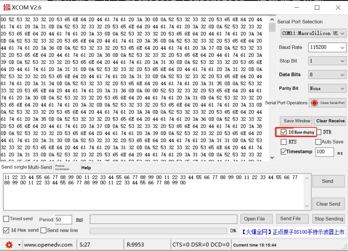
Then when sending data, it can be seen that the Raspberry Pi Pico has sent a flow control character XOFF (0x13):
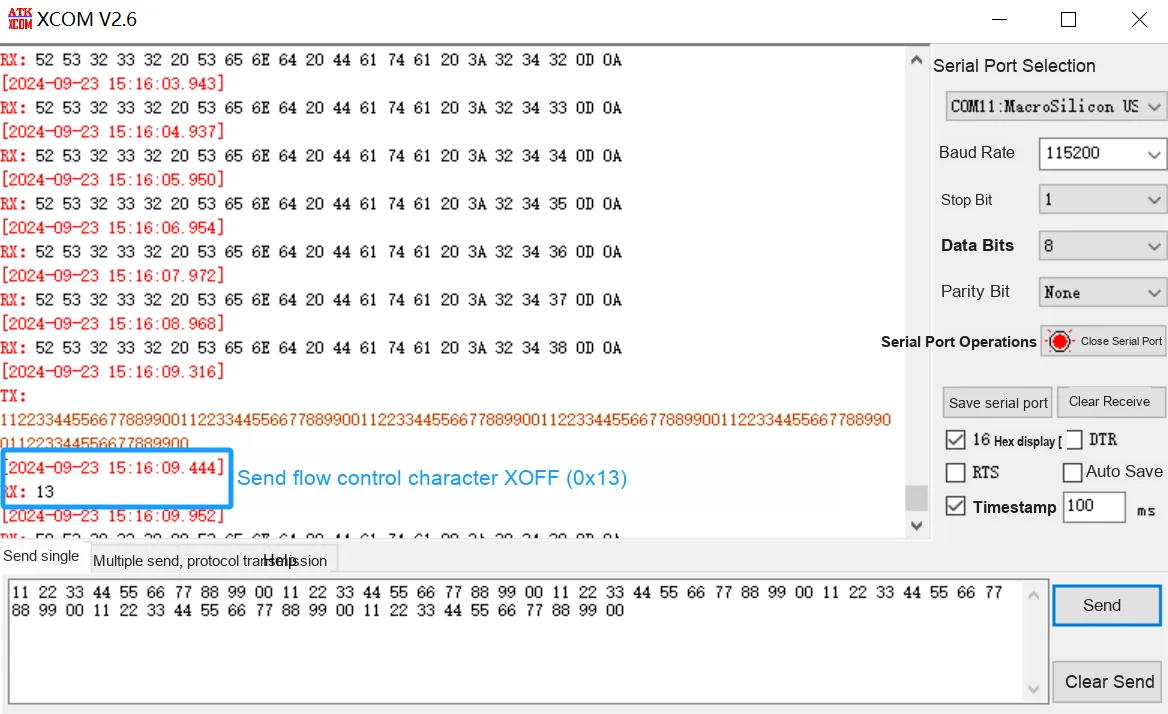
In addition, the size of data received by the Raspberry Pi Pico never exceeds the set buffer size:
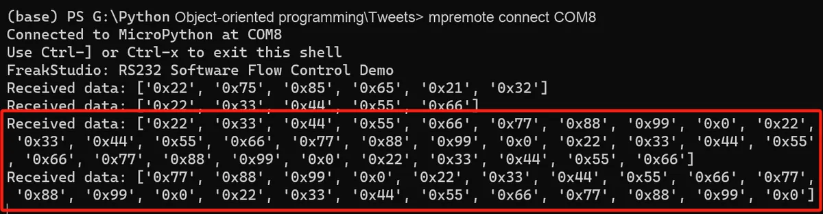
3.5 Application Experiment.mp4 24.9 MB
Based on the above tests, it can be seen that our custom RS232 software flow control communication class can implement the basic functions of transmission suspension and resumption. Compared with hardware flow control, software flow control is easy to use and requires no extra wiring, but it also has certain drawbacks: it relies on special control characters to manage data transmission, which will occupy part of the transmission bandwidth; meanwhile, XON (0x11) and XOFF (0x13) are specific control characters. If the transmitted data itself contains these characters, they may be misinterpreted as flow control commands, leading to erroneous transmission suspension or resumption.
3.6 RS485 Communication
3.6.1 RS485 Communication Fundamentals
The RS-232 communication protocol has the following drawbacks, making it difficult to use in long-distance and industrial scenarios:
- The signal level value is high : the signal level of RS-232 is usually around ± 12V, and may even reach ± 15V; due to the high level, it is easy to damage the chip in the interface circuit. If it needs to be connected to a low-voltage TTL circuit (such as 5V or 3.3V), the equipment must be protected and signal matched through a level conversion circuit
- Low transmission rate : The baud rate of RS-232 is relatively low, especially in asynchronous transmission, the highest rate is only 20Kbps, which is far from enough for the needs of modern high-speed communication, especially in applications that require fast data exchange
- Poor anti-interference : RS-232 uses a single-ended signal transmission method, that is, a signal line and a common ground line constitute a signal loop, this structure is easily affected by common mode interference, so that the signal quality deteriorates, anti-noise performance is weak, especially in long-distance transmission
- Limited transmission distance : The standard stipulates that the maximum transmission distance of RS-232 is 50 feet (about 15 meters), and in practice, the transmission distance is generally not more than 50 meters. After exceeding this distance, the signal will be greatly attenuated, and the reliability of communication cannot be guaranteed
Therefore, subsequent engineers developed the RS-485 Communication Protocol. Compared with the RS-232-C interface, RS-485 has remarkable advantages in terms of transmission distance, anti-interference capability, multi-device communication and other aspects: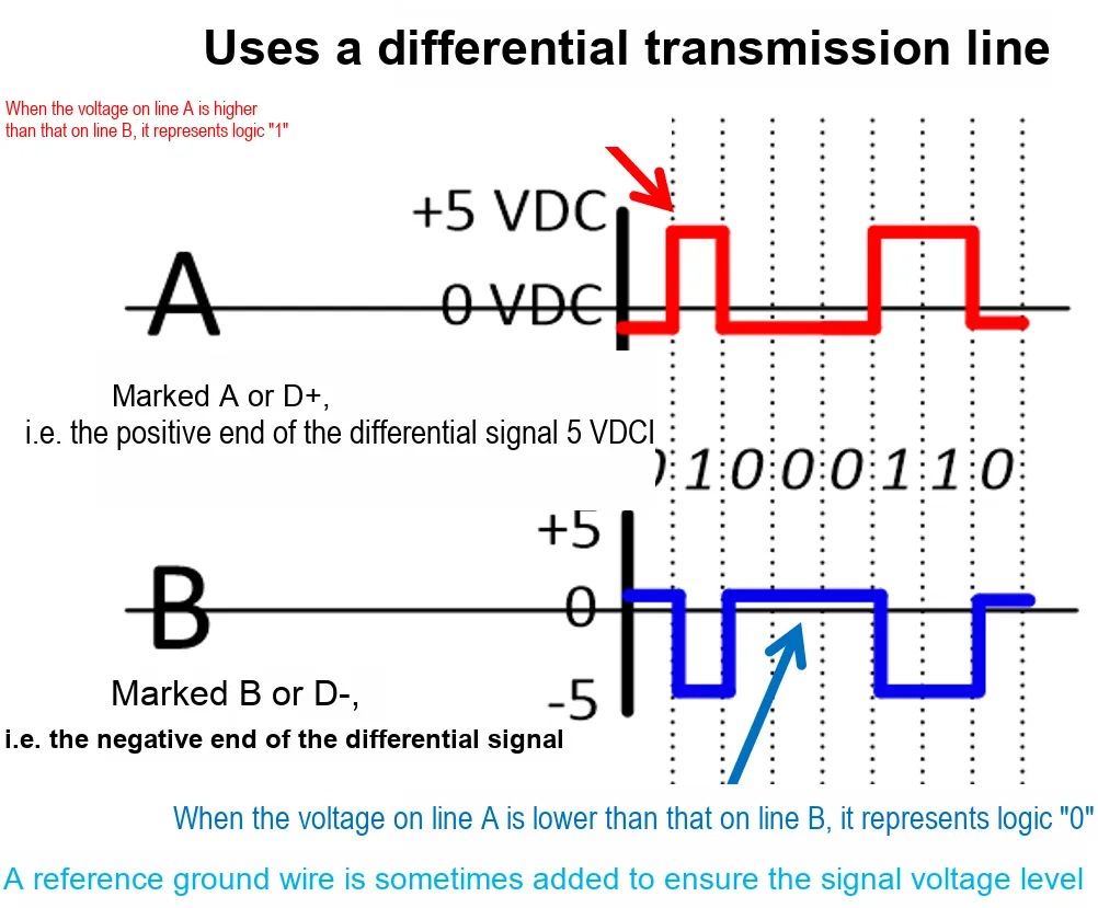
- Differential Signal Transmission: RS-485 uses two signal lines (A and B) to represent "0" and "1" through voltage difference; this differential transmission method can effectively resist electromagnetic interference and ensure stable communication in noisy environments.
- Multipoint Communication: RS-485 allows multiple devices to be connected to the same bus, typically supporting 32 transmitters and 32 receivers, and even more devices can be connected via repeaters, which makes RS-485 highly suitable for scenarios requiring interconnection of multiple devices.
- Long-distance transmission: The maximum transmission distance of RS-485 can reach 1200 meters (approximately 4000 feet), and the transmission speed is inversely proportional to the distance; as the transmission distance decreases, the data transmission rate can be increased, up to a maximum of 10 Mbps
Unlike RS-232 or TTL, RS-485 operates in half-duplex mode in most applications, meaning only one device can transmit data at a time while all other devices remain in the receiving state, thus an additional protocol is required to coordinate communication between devices.
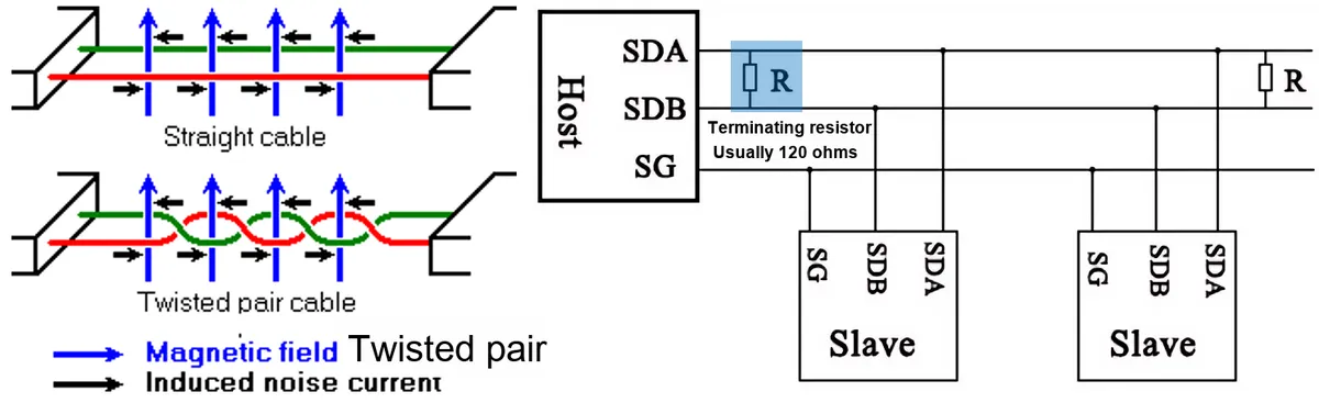
The typical topology of an RS485 bus is that multiple devices are connected in series on a single trunk line; each device is equipped with an independent transmitter and receiver, and shares a pair of communication lines (A and B). We usually use twisted-pair cables to reduce electromagnetic interference and noise. Meanwhile, for long-distance or high-speed transmission, terminal resistors (typically 120 ohms) are usually added at both ends of the bus to avoid signal reflection and interference.
In the master-slave architecture of RS-485 communication, different devices can be divided into two roles:
- Master device (Master): responsible for controlling the entire communication process, initiating data requests, and sending commands and data to slave devices
- Slave Devices: Each slave device has a unique device ID (address), and passively responds to the requests from the master device during communication. Only when the master device sends a matching address to it will the slave device process the data and send a response as required.
The communication process can be summarized as follows: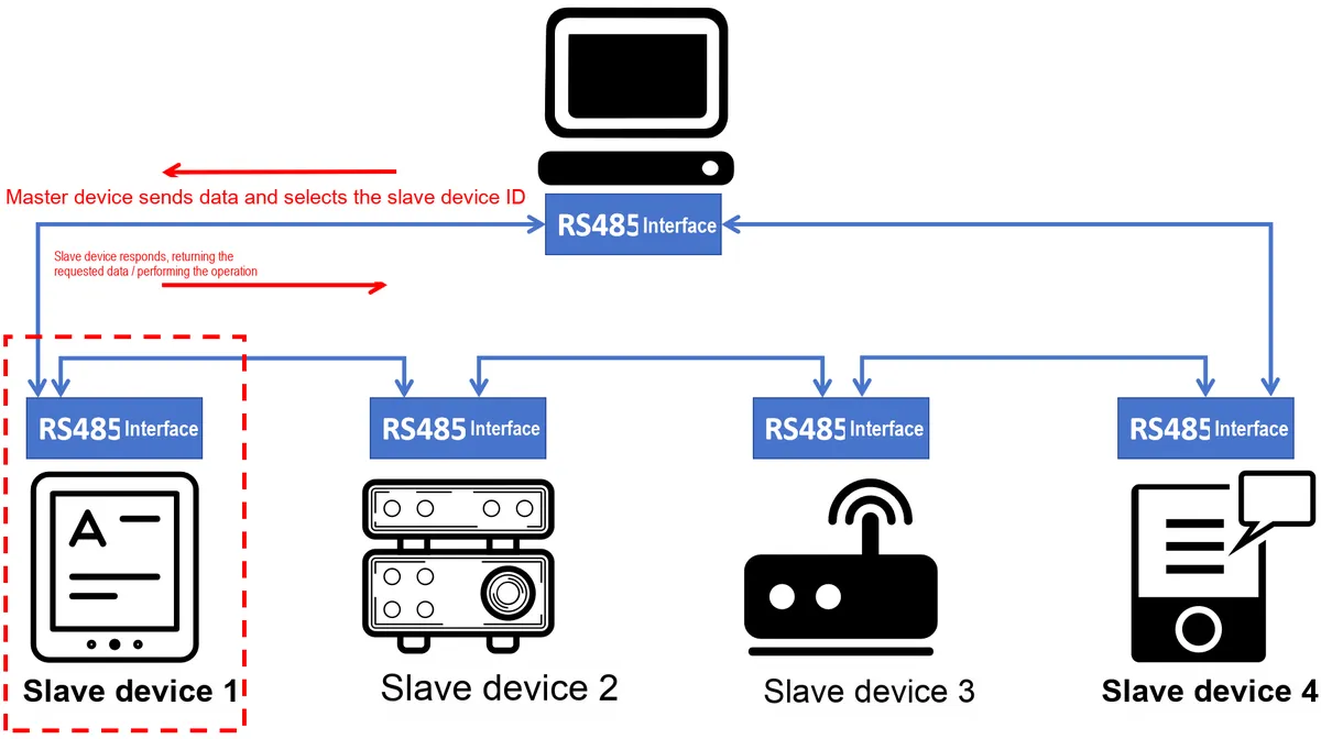
- Master device data transmission: The master device transmits data via the RS-485 bus, which includes the address of the target slave device (slave device ID) and specific data; both line A (+ signal) and line B (- signal) are connected to all slave devices simultaneously.
- Slave device listening: All slave devices monitor the data streams on lines A and B, and check the address information sent by the master device
- Slave device selection: When a slave device detects that the address in the transmitted data packet matches its own slave device ID, it will receive the data packet and perform corresponding processing.
- Slave Response: If the Communication Protocol requires the slave device to return data (such as status information, sensor data, etc.), the slave device will send response data to the master device; RS-485 is generally half-duplex, which means only one device can transmit data at the same time, so the transmission of response data needs to be carried out according to a predetermined timing sequence
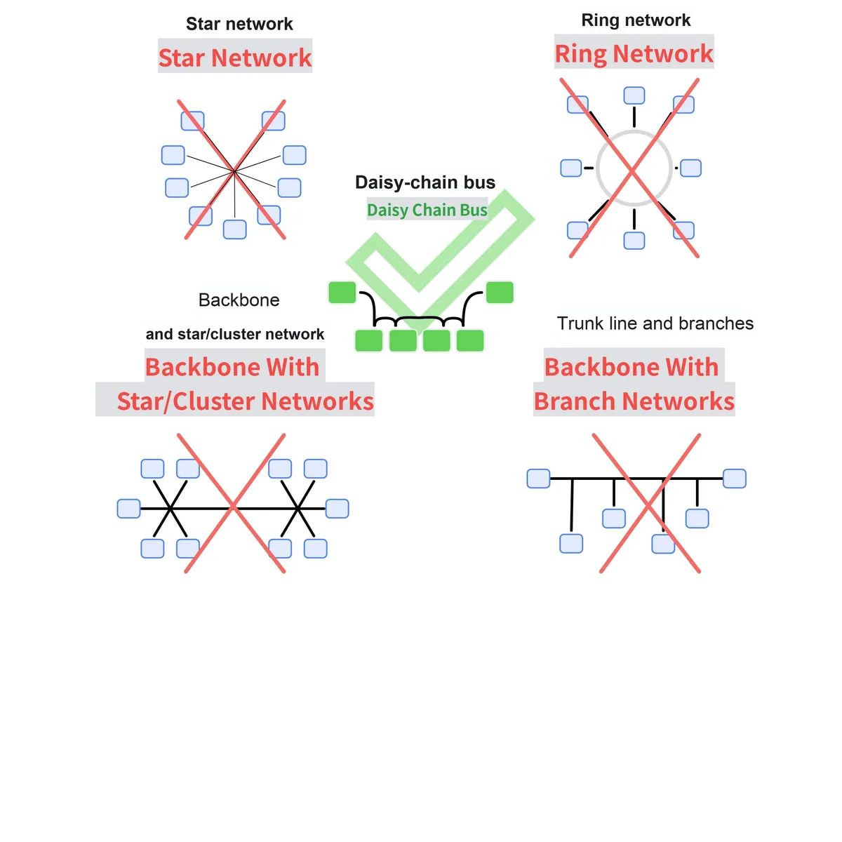
With the exception of the daisy-chain bus (which connects devices in series one after another to form a communication link with a single path), other topologies are not recommended for use in RS485 communication, as they will cause severe signal reflection and interference problems. If a topology such as a star topology must be used, an RS-485 hub or repeater must be used to avoid signal reflection and interference:
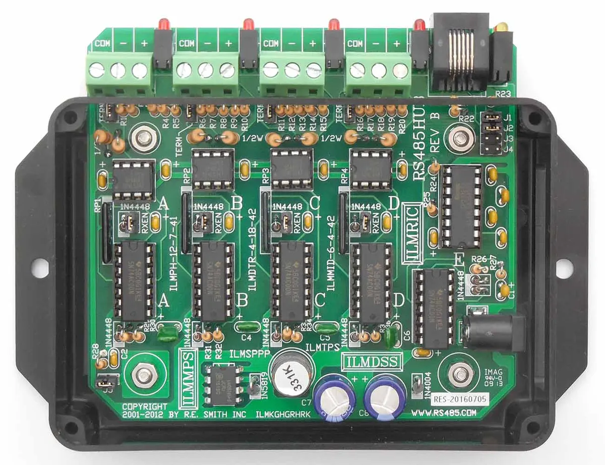
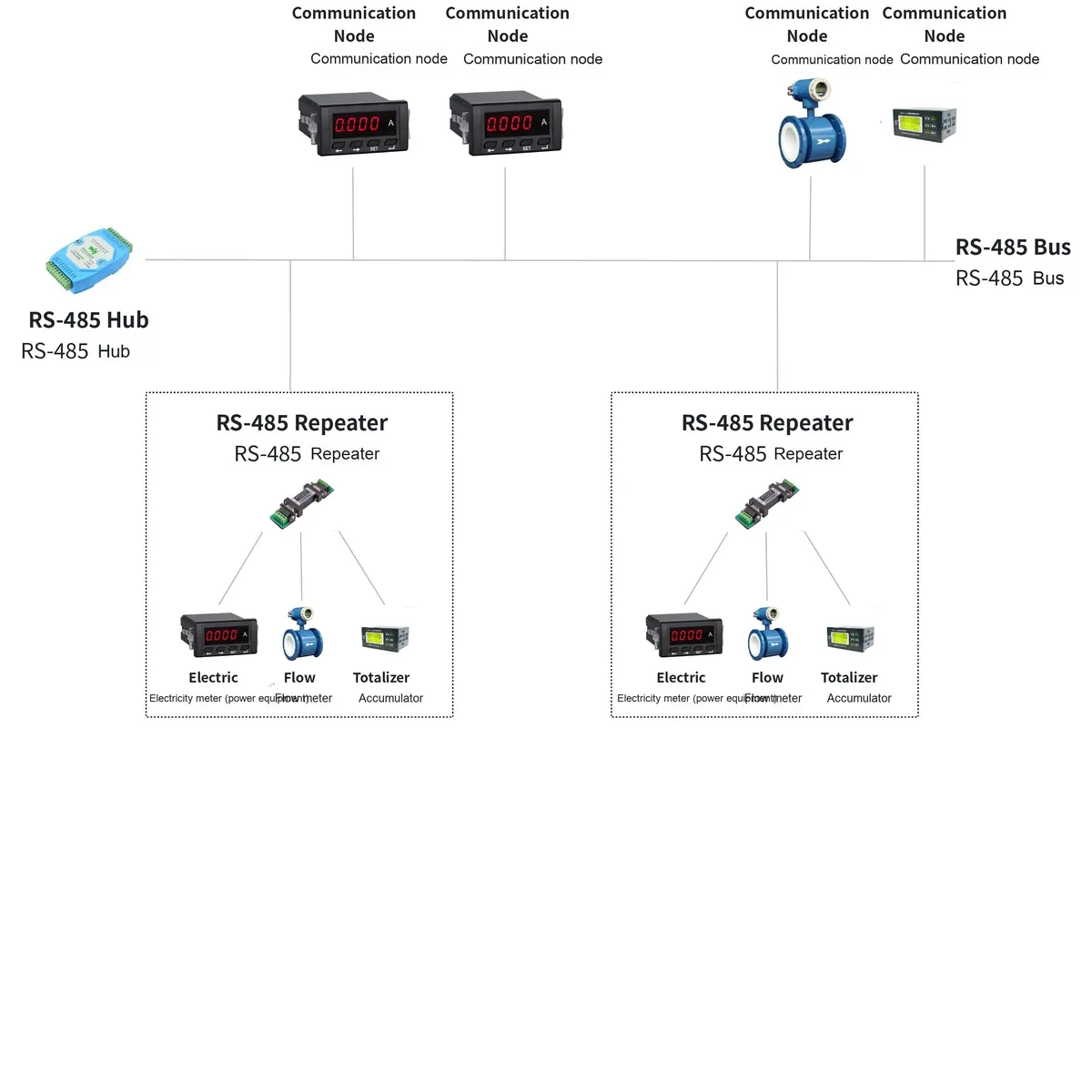
When using RS485 communication, it is strictly prohibited to route the RS-485 signal cables and power cables together in a bundled manner, as power cables generate strong electromagnetic interference that will disrupt the signal cables transmitting data; meanwhile, the RS-485 bus requires single-point grounding, meaning there shall be only one grounding point on the bus. If multiple grounding points occur, potential differences between ground wires will be caused, which further leads to common-mode interference and affects the stability of communication.
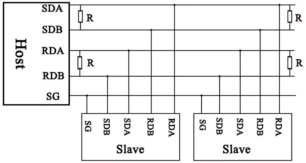
RS485 communication also supports full-duplex data transmission, in which TX and RX communicate via separate dedicated lines; however, under this configuration, slave devices cannot communicate directly with each other, and all data transmission between them must be routed through the master device.
3.6.2 Introduction to the MAX13487 Chip
The MAX13487E is a high-performance, half-duplex RS-485/RS-422 compatible transceiver featuring ±15kV electrostatic discharge (ESD) protection, while supporting automatic transceiver control function and power-down mode. It supports a maximum communication rate of 500kbps, also enables hot-swapping under power-on condition to avoid data errors, and allows up to 128 transceivers to be connected on the same bus.
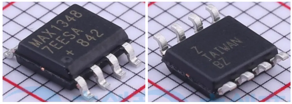
The functions of its pins are as follows:
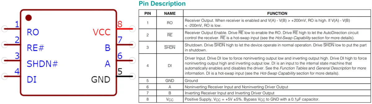
In the table below, we provide a detailed explanation:
Pin Name | Corresponding connection pin | Function Introduction |
RO | MCU UART Input Pin (RX) | The receiver output pin determines whether the output data is 0 or 1 based on the differential voltage between A and B. |
RE | MCU control pin (GPIO) | Receiver output enable pin: driving RE low enables the RO output; driving RE high leaves the enabling and disabling of the receiver under the control of the AutoDirection circuit. |
SHDN | MCU control pin (GPIO) | Drive SHDN to a high level to enable normal device operation; drive it to a low level to place the device into power-down mode for reduced power consumption. |
DI | MCU UART Transmit (TX) Pin | The driver input pin determines the differential voltage between A and B according to the high or low level of DI, so as to realize data transmission. |
GND | Connect to MCU ground | Ground pin, which is connected to the circuit ground to provide a stable reference voltage. |
A | Connect to Bus Line A | Non-inverting signal input/output pin |
B | Connect to Bus Line B | Inverting Input/Output Pin |
VCC | Connect to the + 5V power supply | Positive power supply pin, which provides + 5V power supply. VCC needs to be bypassed to ground through a 0.1µF capacitor to filter out power supply noise. |
The internal structure of the MAX13487E chip is shown as follows:
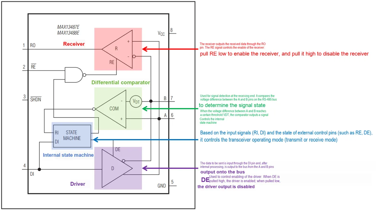
The main working units are the internal finite-state machine, transmitter, differential comparator and receiver. Together with the external pull-up and pull-down resistors for the phase A and phase B signals, the MAX13487 chip can easily implement the automatic transceiving function by monitoring the voltage difference on the data input (DI pin) and the differential signal lines (pins A and B), without requiring the user to use additional GPIO pins to control transceiving.
The typical application circuit of the MAX13487E chip is shown in the following figure:
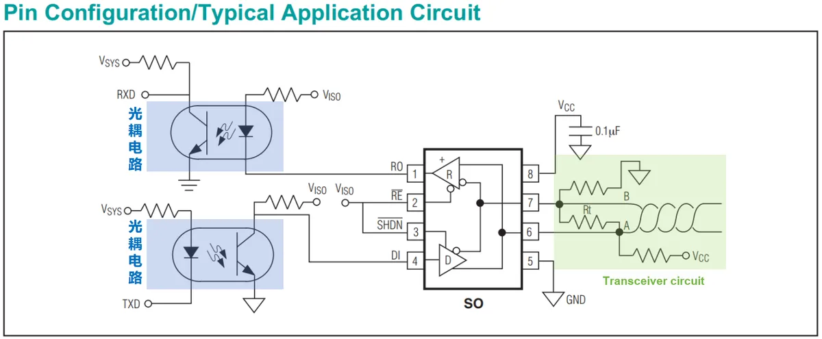
Among them, the TXD pin and RXD pin of the serial port corresponding to the MCU are connected to the RO and DI pins of the MAX13487 chip through an optocoupler isolation unit; the RE and SHDN pins of the MAX13487 chip are both connected to a high level, which means the power-off mode is disabled and the automatic transceiving function is enabled. A termination resistor is connected to the differential signal input/output pins to match the impedance of the communication bus. Meanwhile, the A pin is connected to the power supply via a pull-up resistor, and the B pin is connected to ground via a pull-down resistor, thereby generating a small differential voltage to ensure that the voltage of pin A is higher than that of pin B, so that the bus can maintain a logic "1"(i. e., A > B) when idle.
When multiple devices use the MAX13487 chip for RS485 communication, the connection topology diagram is shown as follows:
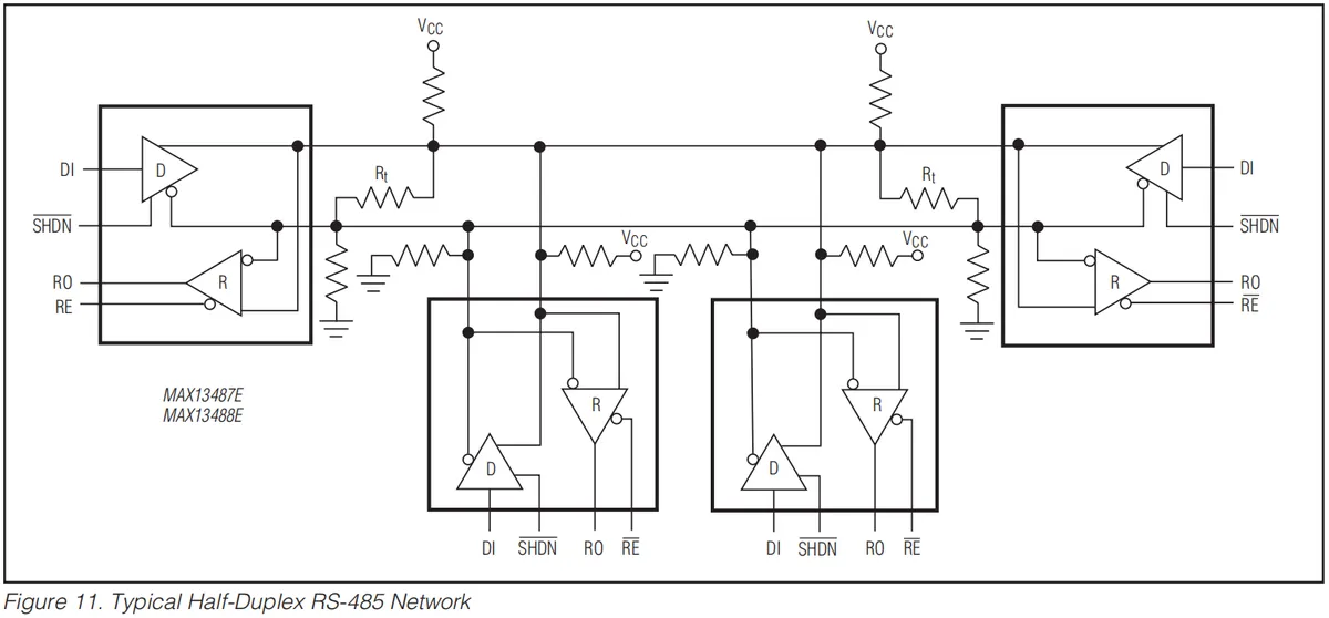
All devices are connected together via a pair of differential signal lines (A and B), and terminating resistors are typically installed at both ends of the bus.
Here, we use a USB-to-485 adapter to enable communication between the Raspberry Pi Pico with an external MAX13487 chip and the host computer. This USB-to-485 adapter adopts the FT232 chip, for which we need to install the corresponding driver. In addition to being downloaded from FTDI's official website,
https://ftdichip.com/drivers/vcp-drivers/
You can also find it in the resource package we provide:

Double-click the left mouse button and follow the steps below to install:
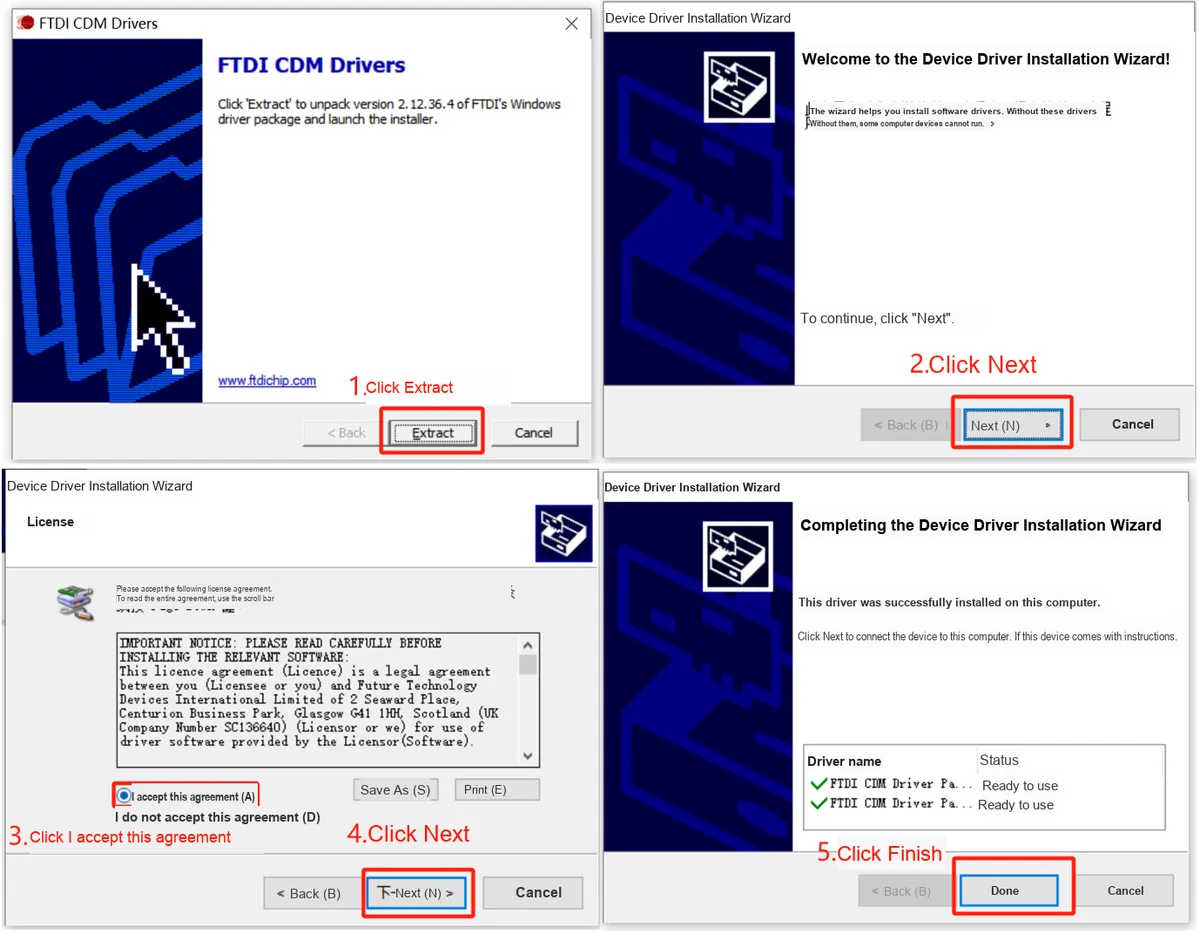
3.6.3 Application Experiment
Here, in the following code, we implement the communication between the Raspberry Pi Pico's external MAX13487 chip and the computer host.
In the following experiment, we need to insert the Fengya No.1 board-Grove interface expansion board into the Fengya No.1 board-serial level conversion board , while opening the RS485-SW DIP switch on the RS485-TXD , RS485-RXD and RS485-EN options, we use the serial peripheral 0 and Fengya No.1 board-serial level conversion board on the MAX13487 chip connection, set the Raspberry Pi Pico receive pin to GPIO17 , send pin to GPIO16 ,:
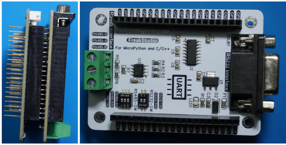
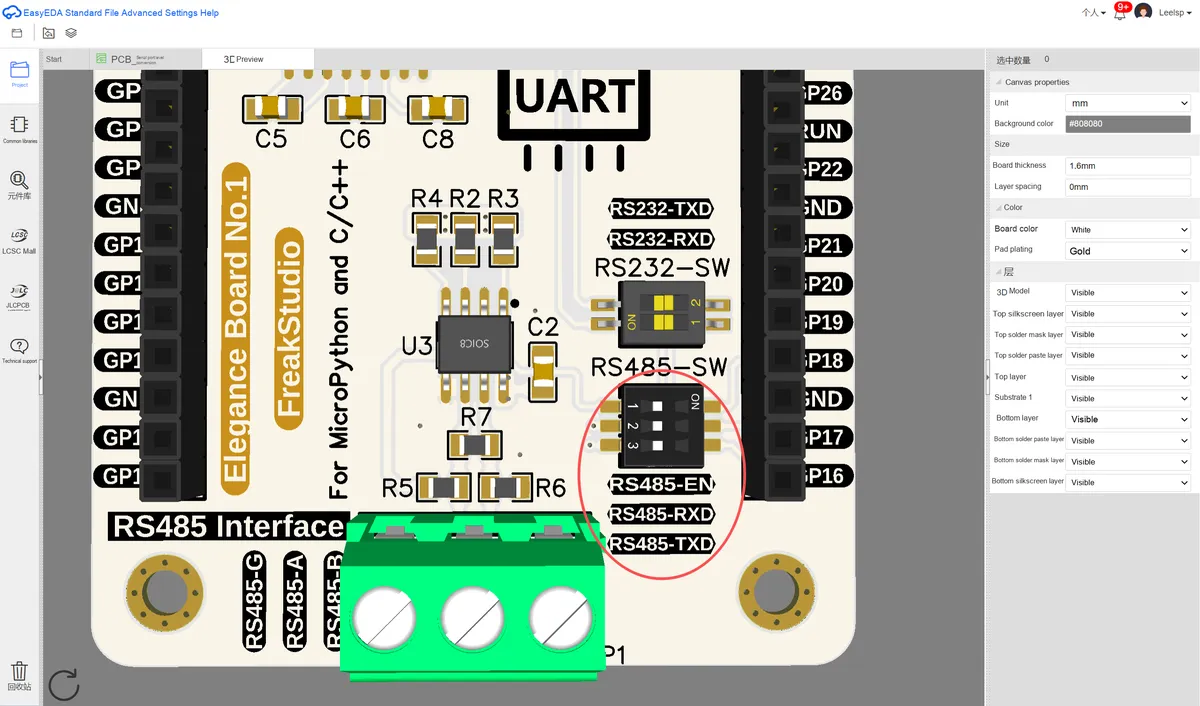
Next, we will Fengya No. 1 Board - Serial Port Level Conversion Board 's RS485 Interface port RS485-A and RS485-B pins to the adapter' s T/R+ and T/R- pins, connect the GND of both devices at the same time, and then connect the adapter to the computer via the USB port. The physical connection diagram is shown below:
In the following routine, we control the RS485 module to send and receive data via the serial port, and switch the working mode through the transmit-receive control pin to ensure normal data flow transmission.
The sample code is located in the folder of the supporting materials as follows: elegance-devkit v1\Demo\12 UART_RS485:
# Python env   : MicroPython v1.23.0
# -*- coding: utf-8 -*-
# @Time    : 2024/9/23 3:53 PM
# @Author  : Li Qingshui
# @File    : main.py
# @Description : UART class experiment, RS485 serial communication

# ======================================== Import Modules =========================================

# Hardware-related modules
from machine import UART, Pin
# Time-related modules
import time

# ======================================== Global Variables ============================================

# UART configuration parameters
UART_TX_PIN : int = 16       # Transmit pin (GPIO16)
UART_RX_PIN : int = 17       # Receive pin (GPIO17)
CONTROL_PIN : int = 18       # Transmit/receive control pin (GPIO18)
BAUD_RATE   : int = 115200   # Baud rate

# Device ID
DEVICE_ID   : int = 1

# ======================================== Functions ============================================

# ======================================== Custom Classes ============================================

# Custom RS485 communication class
class RS485Communication:
    """
    RS485 communication class, used to send and receive data over the RS485 protocol.

    This class implements serial communication over the RS485 protocol, including sending data, receiving data and processing the received data. By controlling the pin that switches the transmit/receive mode,
    it can switch between sending and receiving data. This class is used for point-to-point or multi-point communication between devices, ensuring normal data transmission and correct communication between devices.

    Attributes:
        uart (UART): The serial port object, representing sending and receiving data over the serial port.
        device_id (int): The unique ID of the device, used to distinguish communication data between different devices.
        control_pin (Pin): The control pin, used to switch the transmit/receive mode. When sending data, set the control pin to transmit mode; when receiving data, set it to receive mode.

    Methods:
        send_data(data: str) -> None:
            Send data: send the device ID together with the data to be sent, and switch to transmit mode.

        receive_data() -> Union[bytes, None]:
            Receive data: check whether there is data to receive, and return the received data. If there is no data, return None.

        process_received_data(received: bytes) -> None:
            Process the received data. Decode the data and compare it with the device ID; if the data belongs to the current device, process it; otherwise ignore it.
    """

    def __init__(self, uart: UART, device_id: int, control_pin: int):
        """
        Initialize the RS485 communication object.

        Initialize the RS485 communication object with the specified serial port object, device ID and control pin.

        Args:
            uart (UART): The serial port object, using the specified UART port for data transmission.
            device_id (int): The ID of the device, used to identify this device.
            control_pin (int): The transmit/receive control pin, used to switch the serial port between transmit and receive modes.
        """
        # Set the serial port object
        self.uart = uart
        # Set the device ID
        self.device_id = device_id
        # Set the transmit/receive control pin
        self.control_pin = Pin(control_pin, Pin.OUT)
        # Receive mode initially
        self.control_pin.value(0)

    def send_data(self, data: str) -> None:
        """
        Send data.

        Send data with the device ID over the serial port, and switch the transmit/receive control pin to transmit mode.

        Args:
            data (str): The data to send.

        Returns:
            None
        """

        # Set to transmit mode
        self.control_pin.value(1)
        # Add the device ID and newline character
        message = f"{self.device_id}:{data}\r\n"
        # Send the data
        self.uart.write(message)
        # Wait for the data transmission to complete
        time.sleep(0.1)
        # Switch back to receive mode
        self.control_pin.value(0)

    def receive_data(self) -> bytes:
        """
        Receive data.

        Check whether there is data available to receive, and read it if so.

        Returns:
            bytes: The received data, or None if there is no data.
        """

        # Check whether there is data available to receive
        if self.uart.any():
            # Read the received data
            return self.uart.read()
        # If there is no data, return None
        return None

    def process_received_data(self, received: bytes) -> None:
        """
        Process the received data.

        Decode the received byte data and process it according to the device ID. If the received data is not from its own ID,
        the data is printed. If the received data format is incorrect, it is ignored.

        Args:
            received (bytes): The received byte data.

        Returns:
            None

        Raises:
            ValueError: Raised if the data format is incorrect.
        """

        # Decode the data and strip whitespace
        decoded_data = received.decode('utf-8').strip()
        # Split the data by line and process each message
        messages = decoded_data.split('\r\n')

        # Iterate over the messages
        for msg in messages:
            # If the message is not empty, process it
            if msg:
                # Split the device ID and the message
                try:
                    sender_id, message = msg.split(':', 1)
                    # If the sender ID is not its own ID
                    if sender_id != str(self.device_id):
                        # Print the received message
                        print("Received:", message)
                except ValueError:
                    # If the data format is incorrect, ignore the message
                    print("Received invalid message format:", msg)

# ======================================== Initialization ==========================================

# Power-on delay of 3 s
time.sleep(3)
# Print debug message
print("FreakStudio: RS485 Communication with PC Demo")

# Create the serial port object, set the baud rate to 115200
uart: UART = UART(0, BAUD_RATE)
# Initialize the uart object with a baud rate of 115200, 8 data bits, no parity bit, and 1 stop bit
# Set the receive pin to GPIO9 and the transmit pin to GPIO8
# Set the serial port timeout to 100ms
uart.init(baudrate  = BAUD_RATE,
          bits      = 8,
          parity    = None,
          stop      = 1,
          tx        = UART_TX_PIN,
          rx        = UART_RX_PIN,
          timeout   = 100)

# Create the RS485 communication object
rs485: RS485Communication = RS485Communication(uart, DEVICE_ID, CONTROL_PIN)

# ========================================  Main Program  ===========================================

# Run in a loop
while True:
    # Send test data
    rs485.send_data("Pico RS485 Test")

    # Receive data
    received = rs485.receive_data()
    # If data is received
    if received:
        # Process the received data
        rs485.process_received_data(received)

    # Delay 1 second
    time.sleep(1)
In the above code, we have customized a RS485Communication class to implement RS485 communication. This class uses the device ID to verify whether the received data is the content sent by itself, and the working principle of its core method is as follows:
- When transmitting data, set the control pin to high level to switch the MAX13487 chip to transmit mode; then combine the device ID and data into a message and send it. After the transmission is complete, wait for 100 milliseconds to ensure the data is sent, then switch back to receive mode.
- When receiving data, decode the received data, split it by lines, iterate through each message, and separate the device ID and the message content; if the sender ID does not match the local device ID, print the received message
Here, the reason why the device ID is used to identify the message source and decode the received data is not only that RS485 communication is usually applied in a master-slave communication scenario with one master and multiple slaves, but also to avoid the echo effect in RS-485 communication, which is an interference caused by signal reflection during transmission. This may lead to the situation that after a device sends RS485 data, it receives the previously sent data when receiving data.
Burn the code, open the terminal, launch the serial port assistant, set it to character display mode, and select "Send New Line" when transmitting data:
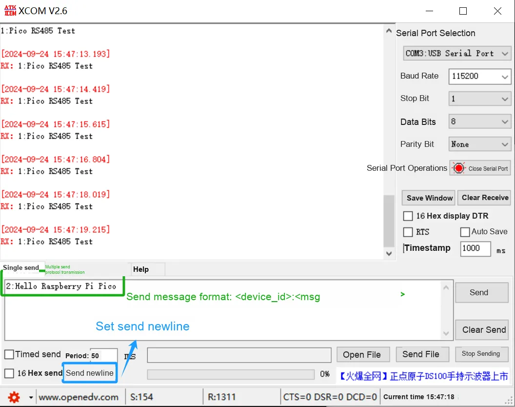
It can be seen that the Raspberry Pi Pico sends data to the computer side periodically. When we send data to the Pico from the computer, please note that the format is as follows:
<设备ID>:<数据内容>\r\nHere, the data we send is: 2: Hello Raspberry Pi Pico.
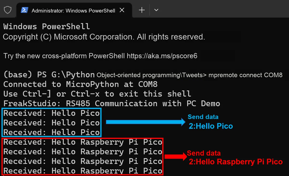
It can be seen that the Raspberry Pi Pico receives the data successfully. If the format of the data we send is incorrect, the Raspberry Pi Pico will throw an exception and print the corresponding data in the terminal:
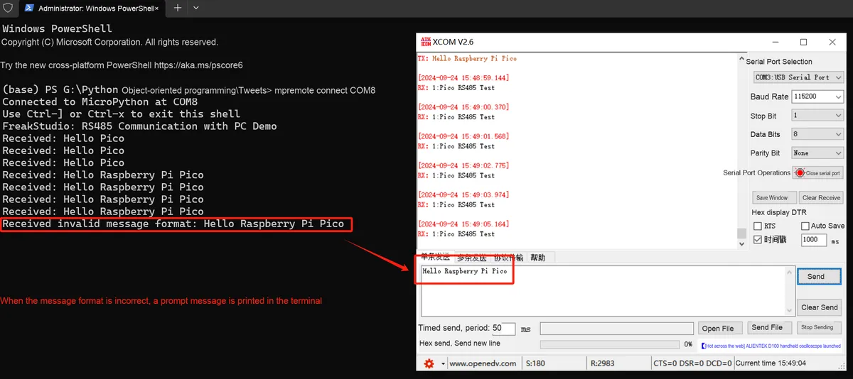
3.6 Application Experiment.mp4 8.8 MB
References
- A Short Article to Help You Fully Understand What Serial Communication Is
https://blog.csdn.net/Neutionwei/article/details/117840686
- Detailed Explanation | Still Confused About Serial Communication? This Article Has You Covered!
https://www.cnblogs.com/wanghuaijun/p/15159261.html
- Essentials of Microcontroller Use Learning about Peripherals: Serial Communication
https://www.renesas.com/us/en/support/engineer-school
- UART: A Hardware Communication Protocol Understanding Universal Asynchronous Receiver/Transmitter
https://www.analog.com/en/resources/analog-dialogue/articles
- What Is Universal Asynchronous Receiver-Transmitter (UART)? Meaning, Working, Models, and Uses
https://www.spiceworks.com/tech/networking/articles/what-is-uart/
- Working Principle and Design of FIFO https://blog.csdn.net/Jackiezhang1993/article/details/129540259
- Pack and Unpack of Simple Custom Protocols (Including Serial Port Touch Screen)
https://blog.csdn.net/m0_46577050/article/details/123289537
- UART IRQ issue
https://forum.micropython.org/viewtopic.php?t=3398
- UART IRQ/Callbacks and Class Example
https://forum.micropython.org/viewtopic.php?t=4414
- UART IRQ
https://forum.micropython.org/viewtopic.php?t=1448
- peterhinch/micropython-samples
https://github.com/peterhinch/micropython-samples?tab=readme-ov-file
- A Clear Explanation of LSB, MSB, Big/Little Endian Modes and Network Byte Order
https://www.cnblogs.com/lingyejun/p/8312838.html
- 【Diao Ye Learns Programming】MicroPython Manual for RP2 (Pico) UART (Serial Bus)
https://blog.csdn.net/weixin_41659040/article/details/133379977
- Notes for Waveshare Raspberry Pi PICO —— 5. UART (Universal Asynchronous Receiver/Transmitter)
https://blog.csdn.net/weixin_51684355/article/details/127033267
- STM32 Basic Tutorial (Part 7): Port Multiplexing and Remapping
https://www.guyuehome.com/38427
- Python serial port listener
https://stackoverflow.com/questions/26047544/python-serial-port-listener
- use of select.poll() with multiple uarts
https://forum.micropython.org/viewtopic.php?t=1741
- Usage and Example Analysis of Serial Port select Function
https://blog.csdn.net/zhaodeming000/article/details/98618097
- Serial Communication Based on Finite-State Machine
https://www.cnblogs.com/quliuliu2013/p/13300834.html
- IMU_Python_Reading
https://github.com/Can-Guo/IMU_Python_Reading
- Embedded Development Diary (3) – Receiving and Processing JY61 Sensor Data with Python
https://blog.csdn.net/wulitaotao96/article/details/89303763
- Raspberry Pi Pico uses WitMotion JY61/JY901/JY61P gyroscopes
https://blog.csdn.net/qq_44712946/article/details/127644066
- Buffer Protocol — Python Documentation
https://cainiaojiaocheng.com/Python/docs/3.8/c-api/buffer
- A Brief Discussion on STM32 UART Communication (Part 2): Custom Frame Format and Timeout Reception
https://blog.csdn.net/weixin_40134414/article/details/105374200
- Linux Stream Devices and Block Devices: Implementing Efficient Data Transmission (Linux Stream Devices and Block Devices)
https://www.idc.net/help/150866
- Get a Clear Picture of [RS-485 Communication Interface] in One Go
https://blog.csdn.net/hqwest/article/details/141433106
- Finally Explained Thoroughly: The Most Detailed RS485 Serial Communication in History!
https://blog.csdn.net/weiqifa0/article/details/103917713
- All about RS485 – How RS485 Works
https://www.seeedstudio.com/blog/2021/03/18
- RS485 Wiring, Communication And Difference With RS232
https://www.renkeer.com/what-is-rs485/
Version Record
Version Number | Modifier | Time | Content |
v1.0.0 | Li Zisheng | 2025/09/16 | Initialize the document, based on MicroPython version V1.23.0. |
v1.0.1 | Li Zisheng | 2025/12/05 | Replace the image: the image for Section 0 is pending modification. |
v1.1.0 | Li Zisheng | 2025/12/05 | The image has been modified successfully. |
v1.1.1 | Li Zisheng | 2025/12/21 | Document Optimization |
v1.1.2 | Li Zisheng | 2025/12/26 | Document Optimization |