
Contents
- 1. Hardware Explanation
- 1.1 Basic Concept and Structure of MCU
- 1.2 Basic Structure and Concepts of GPIO
- 1.3 Overview of GPIO on Raspberry Pi Pico
- 2. Software Control Method
- 2.1 Constructor of the machine.Pin Class
- 2.2 Other Methods of the machine.Pin Class
- 2.3 Constructor method of the machine.Signal class
- 2.4 Other Methods of the machine.Signal Class
- 3. Application Examples
- 3.1 GPIO Read/Write Example
- 3.2 GPIO External Interrupt Example
- 3.3 Signal Class Routines
- 3.4 Stepper Motor Control via GPIO
- 3.5 Rotary Encoder Experiment
- 3.6 Five-way Button Experiment
- References
- Version Record
1. Hardware Explanation
1.1 Basic Concept and Structure of MCU
Before we start learning about the GPIO of the Raspberry Pi Pico, let's first explain several core "hardware basic concepts" in simple terms. The Raspberry Pi Pico is an MCU development board, and you can understand an MCU (Microcontroller Unit) as an ultra-miniature dedicated computer — it cannot handle as many tasks as our desktop/laptop computers, but it is specifically responsible for controlling a certain electronic device (such as a smart light, a remote control, or a small toy you make with the Raspberry Pi Pico): for example, when you use the Pico to control an LED to turn on and off, this core component that "issues commands and manages execution" is the MCU.
MCU (Microcontroller) is widely used to control all types of electronic devices, and an MCU consists of a CPU (Central Processing Unit), a memory, and additional circuits that implement various peripheral support functions:
- CPU (Processing Unit): CPU operates by reading programs and executing instructions, which include reading data, performing calculations and comparisons, and generating other operations based on the comparison results; simply put, it is responsible for "thinking and issuing commands", such as judging "whether it is time to turn on the LED now" and "calculating what the sensor data is", and all the program code you write is executed by the CPU.
- Memory (storage device): The functions of a memory device include storing data (such as the values collected by a temperature sensor) and storing the program itself;
- Peripherals (the "hands, feet, and senses" of an MCU): Peripherals can implement functions such as analog-to-digital conversion, signal input/output, time measurement, time monitoring, and host communication; they are responsible for "handling the actual tasks", for example:
- Want to light up an LED? Use the GPIO (General Purpose Input/Output peripheral) as your "hand" to control the circuit;
- Want to read temperature? Rely on the ADC (Analog-to-Digital Converter peripheral) as the "sense organ" to convert the analog signal from the sensor into a digital signal that the CPU can understand;
- Want to transfer data with a computer? Use UART/USB (communication peripherals) as your "mouth and ears".
Peripherals, memory and the CPU are connected via a bus, which acts as the "expressway" inside an MCU:
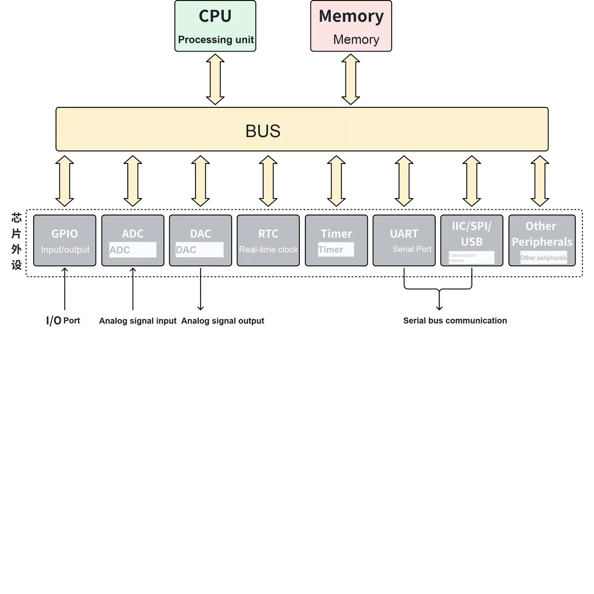
All data and instructions must be transmitted via the bus: for example, if the CPU wants the GPIO to turn on an LED, it has to send the "turn on LED command" to the GPIO peripheral through the bus; the sensor data read by the peripheral also has to be transmitted to the CPU via the bus.
The bus structure of the Raspberry Pi Pico is as follows:
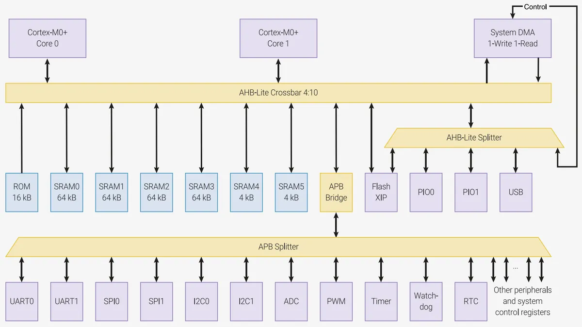
It can be seen that Core 0 and Core 1 are connected to the DMA unit, SRAM memory unit, APB bus bridge and some high-speed peripherals (such as FLASH XIP, PIO, USB, etc.) through the AHB high-speed bus matrix structure. The APB bus bridge is connected to the APB bus, which mounts other low-speed peripherals, such as UART, SPI, IIC, ADC, PWM, timers, watchdog, RTC real-time clock, etc.
When we want to use a certain peripheral to implement a specific function, such as controlling a GPIO to light up an LED, we are essentially operating "registers": they are "special dedicated storage circuits" inside the CPU or in peripheral circuits like GPIO and ADC, and are ultra-high-speed temporary storage units — they are far faster than conventional memory, but due to the precious internal space of the chip, only a small number of such units are available (unlike memory which can store large amounts of data);Each peripheral (such as GPIO or a timer) corresponds to several "dedicated registers"; when the CPU wants to control a specific peripheral, it simply accesses the corresponding registers of that peripheral directly.
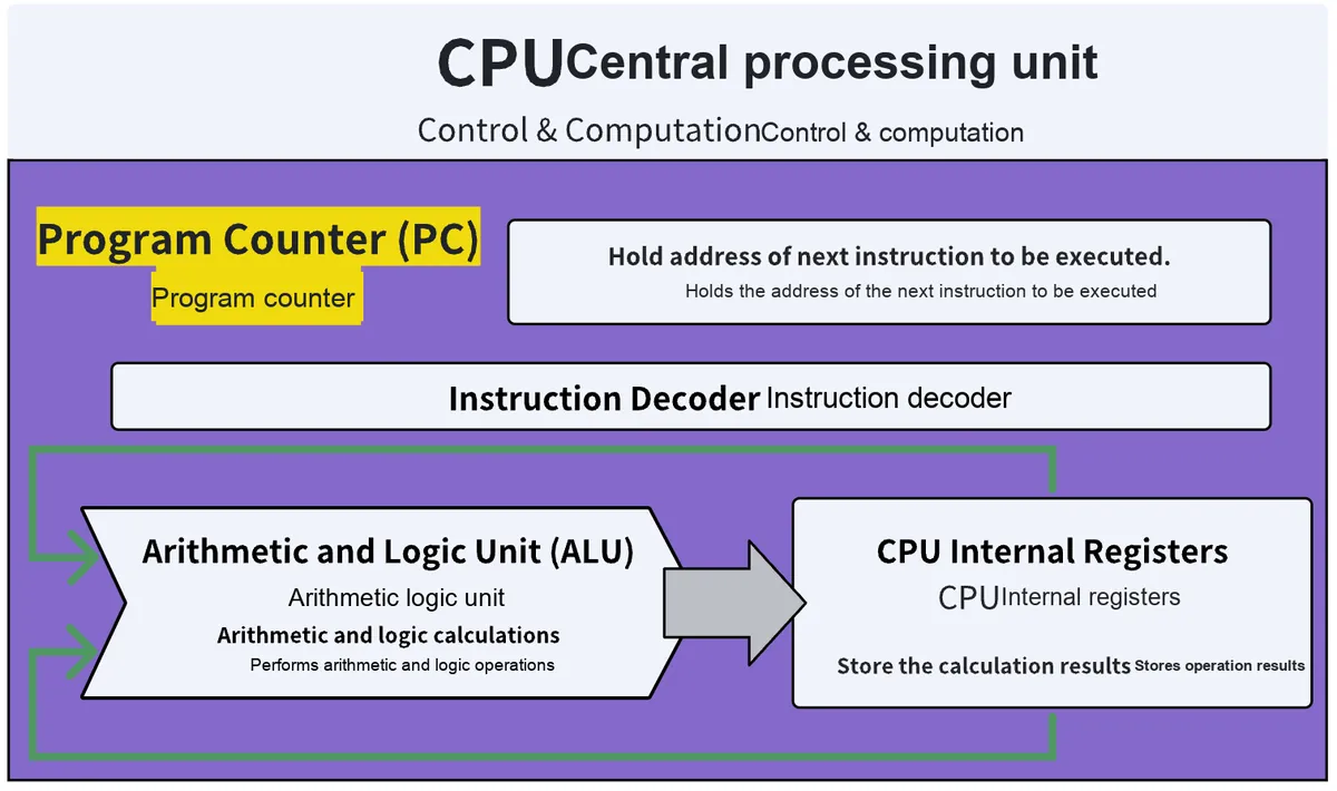
Registers can be divided into the following two types:
- Special registers: They serve dedicated, fixed purposes and cannot be used arbitrarily — for instance, the registers that control GPIO pins are the "exclusive drawers" dedicated to managing GPIO ports, which can only be used to configure the input/output mode and high/low level of GPIO; the registers that manage timers are solely responsible for setting the timing duration.
- General-purpose register: it serves as the CPU's own "temporary workbench", used to store information such as calculation results and the CPU's current execution state, and programmers can flexibly use it to assist program operation.
CPU controls peripheral devices by reading from and writing to the dedicated registers corresponding to the peripherals to issue commands or read data:
- Want to make a certain GPIO pin output a high level? Just locate the register named "GPIO Output Control" and write a "1" to the corresponding bit position.
- Want to read the sensor data from the ADC? Just directly read the value stored in the register named "ADC Data".
Why should MicroPython developers also understand registers? (Core Key Points)
You might ask: "I write code entirely in MicroPython by calling library functions (for example machine.Pin (25, machine.Pin.OUT). on ()), so why do I still need to understand registers? "
This is because the library functions of MicroPython essentially encapsulate register read and write operations into simple commands, but in many scenarios, you still need to directly work with registers — especially for the advanced features of the Raspberry Pi Pico:
- Scenario 1: Advanced operations not covered by the MicroPython library such as DMA operations, advanced PIO (Programmable I/O) configuration, and precise clock control: the basic MicroPython library does not provide a ready-made simple function, so in this case you have to use
machine.mem32(the register read-write interface of MicroPython) to directly read and write registers to implement the function.To give a straightforward example: if you need to configure DMA transfer, you first have to find the address of the DMA control register, then usemem32[address] = configuration valueto set the parameters, and usemem32[address]to read the transfer status. - Scenario 2: Understand both the what and the why, and avoid "Black box programming": Understanding registers allows you to see exactly what operations the
pin.on ()you wrote actually triggers in the underlying hardware (essentially writing a 1 to the GPIO output register). This helps you grasp the correspondence between code and hardware, rather than just mindlessly copying code to call a function. - Scenario 3: Troubleshooting and Custom Functions: When your MicroPython program encounters hardware-related bugs (such as abnormal GPIO output or failed DMA transmission), understanding registers allows you to quickly locate the problem (for example, checking whether the configuration values of registers are correct); if you want to implement custom functions that are not available in library functions (such as a special GPIO interrupt trigger mode), you also need to make adjustments via registers.Simply put, registers are the "hardware operation shortcuts" in a microcontroller — through them, we can quickly access and manipulate low-level hardware resources such as IO ports, DMA, and timers, and they are also the necessary path for MicroPython to operate the advanced functions of the Pico.
1.2 Basic Structure and Concepts of GPIO
GPIO (General Purpose Input/Output) ports are used to process incoming and outgoing digital signals:
- As an input port: it can be used to transmit the on/off signal received from the switch or the data received from the sensor to the CPU.
- As an output port: it can drive external devices according to CPU instructions and calculation results, for example, driving an LED display based on the calculation results, or outputting a PWM drive signal to a motor.
GPIO is referred to as a "general-purpose" input/output port because each of its pins can be freely configured as either an input or an output. In early microcontroller units (MCUs), by contrast, each port was dedicated exclusively to either input or output functionality.
The logical structure of an example GPIO in the Raspberry Pi Pico is shown in the following figure:
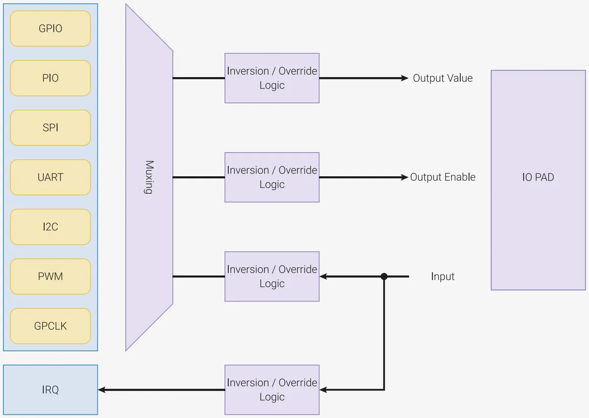
The figure above shows the control logic architecture diagram of GPIO pins:
- Left side: Peripheral function pool (
GPIO/PIO/SPI/UART/I2C/PWM/GPCLK) These are the "functional modules" inside Pico - each module can "take over"GPIO, allowingGPIOto implement corresponding functions, such as selectingSPI,GPIObecomes the pin forSPIcommunication; selectingUART, GPIO becomes the serial port pin; selectingGPIOcorresponds to SIO software control (emphasized later); - Muxing (Multiplexer) acts as the "control switch" for GPIO — it is responsible for selecting one module from the function pool on the left to serve as the "commander" of the current GPIO, and this "module selection" operation is actually configured via
GPIOx_CTRLregister'sFUNCSELbits; - Inversion/Override Logic (Reverse/Override Logic) ×4, which acts as a "fine-tuner" for GPIO signals and can modify the original level signals:
- First: Control
Output Value(the level output by GPIO to the external device), which can invert the level output by the peripheral (for example, if the peripheral sends a high level, the GPIO actually outputs a low level), or forcibly set it to a fixed high or low level; - Second: Control
Output Enable(GPIO output enable), which determines whether the GPIO is in "output mode"(sending signals outward) or "input mode"(receiving external signals); - Third: Control
Input(a signal input from an external source to the peripheral), which can invert the externally received signal before transmitting it to the selected module; - The fourth one: control
IRQ(interrupt signal), which determines whether to convert the GPIO signal into an "interrupt notification" and send it to the CPU (for example, when a key is pressed, it triggers the CPU to process it immediately).
- First: Control
- An IO PAD acts as an "adapter" between GPIO and "external circuits"(such as LEDs and sensors): it is responsible for converting the weak signals inside the chip into voltage/current compatible with external circuits, while protecting the chip from being damaged by static electricity.
- The IRQ (interrupt module) receives signals from the GPIO, and when a predefined condition is met — for instance, the signal level transitions from low to high — it sends an "urgent notification" to the CPU, prompting the CPU to suspend its current tasks and handle the event from the GPIO.
The "controller" of GPIO is selected via the Muxing (multiplexer), which falls into two scenarios:
- Case 1: SIO software control. Select the "GPIO" peripheral, and when Muxing selects the option from the left function pool
GPIO, the GPIO is controlled by the registers of SIO (Software Input/Output). This is the scenario of "manually controlling GPIO via software": for example, when you write in MicroPythonPin (25, Pin.OUT). on (), you directly write the logic level to the GPIO through the software registers in SIO, and the state of the GPIO is completely determined by the code you write. - Case 2: Peripheral automatic control. When selecting other peripherals (such as SPI/UART/PIO, etc.) and choosing the
SPI/UART/PIOand other peripherals on the left side in Muxing, the GPIO is controlled by the corresponding peripheral module hardware, which is the scenario of "hardware automatic GPIO control": for example, after selectingSPI, the SPI module will automatically control the level transition of the GPIO to transmit and receive data, without the need for you to manually set the level;SelectPWM, the PWM module will automatically drive the GPIO to output alternating high and low PWM waves, and you only need to configure the parameters of PWM.
For the GPIO of the Raspberry Pi Pico, the control over GPIO is actually realized by writing to and reading from different bits of the GPIOx_STATUS register and the GPIOx_CTRL register.
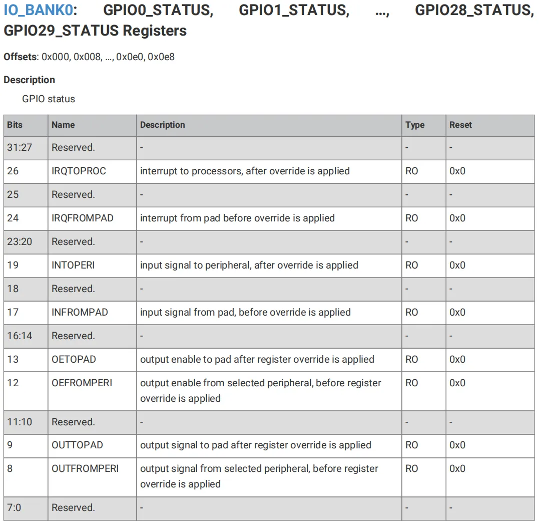
GPIOx_STATUS register is a status panel that can only be read but not modified (marked as RO = Read-Only), and its function is to "inform you of the current real status of GPIO ", for example:
- Read
INFROMPADbit: It can tell whether the original signal received by the GPIO from an external source is high or low; - Read
OUTTOPADbit: It allows you to know whether the signal currently output by GPIO to the external device is high or low; - Read
OETOPADbit: It can identify whether the current GPIO is in "output mode" or "input mode".
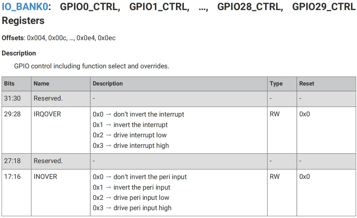
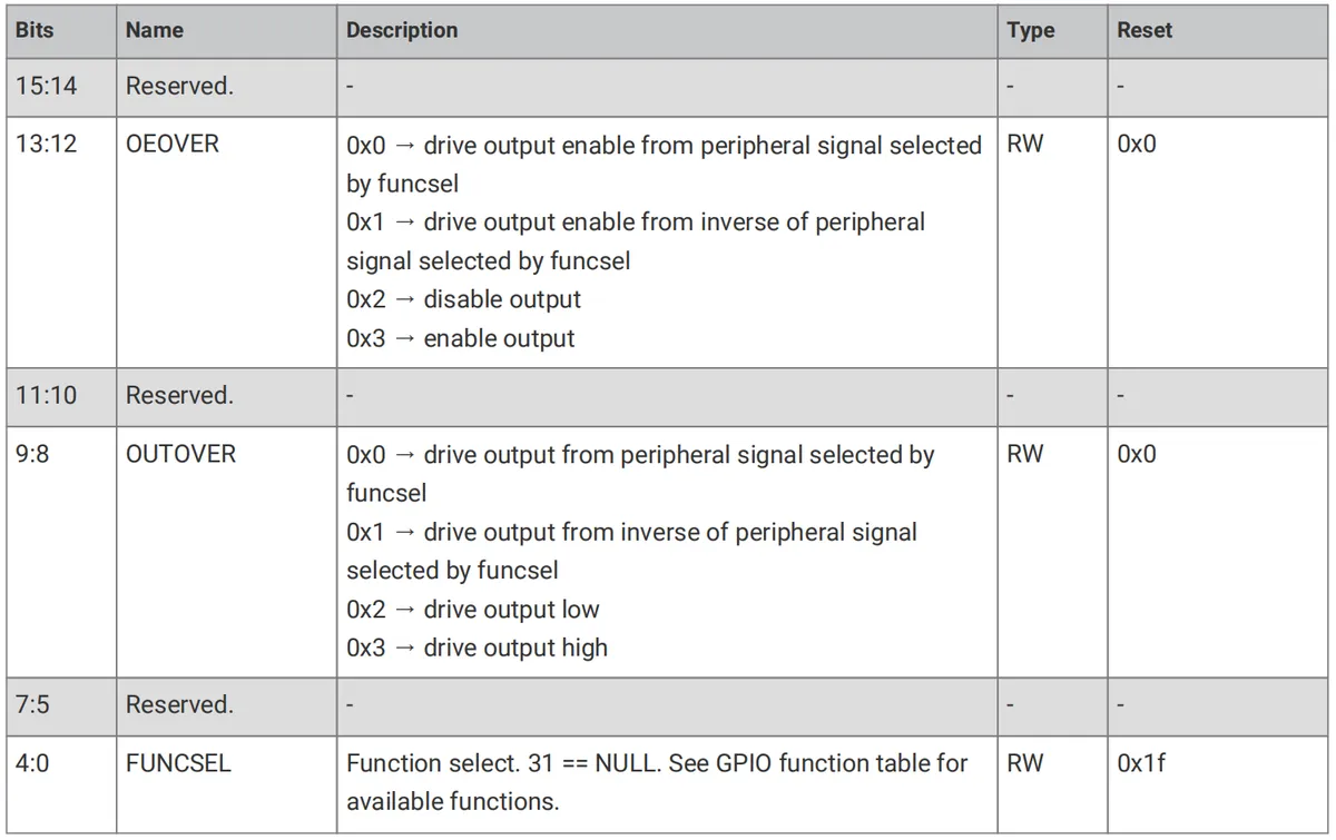
GPIOx_CTRL register serves as the configurable control center (type: RW = read/write), and all operations you perform on GPIO such as function configuration and signal inversion are implemented by writing to this register:
- Use
FUNCSELto selectGPIOfunctions:FUNCSELrefers to bits4:0(5 bits) of the CTRL register, and its value corresponds to "which peripheral to select". For example, ifF1of GPIO0 is SPI0 RX, then writingFUNCSELwith0x00(assuming F1 corresponds to the value 0x00) will switch GPIO0 to the receive line of SPI0; - Signal Inversion / Forced Level: If you need to "invert the output signal of the GPIO"(e. g., the peripheral outputs a high level but the GPIO actually outputs a low level), you can adjust these bits in the CTRL register:
INVERS: Controls whether the "peripheral input signal" is inverted;OUTOVER: Force the GPIO to output high/low (e. g., regardless of what the peripheral outputs, directly set the GPIO to output high).
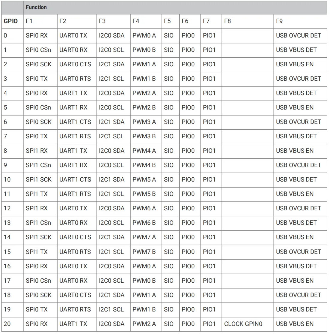
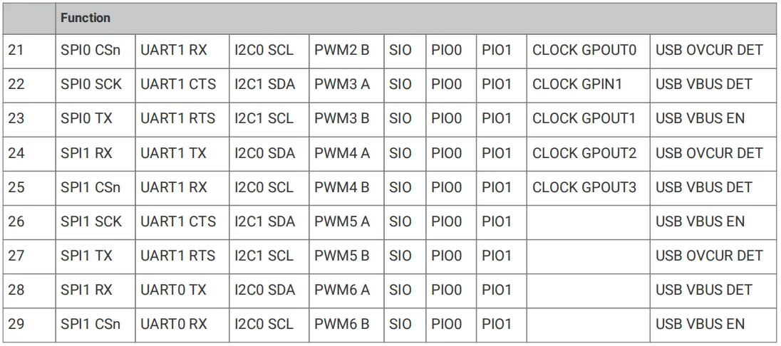
The figure above is the "list of functions that each GPIO can switch between", which corresponds to the previously mentioned "Muxing selection":
- Each row corresponds to one GPIO (e. g., the first row represents GPIO0);
- Each column (F1 to F9) represents the "function options" available for this GPIO (for example, F1 of GPIO0 is SPI0 RX, and F2 of GPIO0 is UART0 TX).
When we operate the GPIOx_CTRL register's FUNCSEL bits, we are selecting the function corresponding to column F here — for example, if you select "F5 (SIO)", the GPIO will be controlled by SIO software; if you select "F1 (SPI0 RX)", the GPIO will become the receive pin of SPI.
Each GPIO is connected to the off-chip world via a "Pads". Pads are the electrical interfaces between the on-chip logic and external circuits, which convert signal voltage levels, support higher currents, and provide protection against some electrostatic discharge (ESD) events.
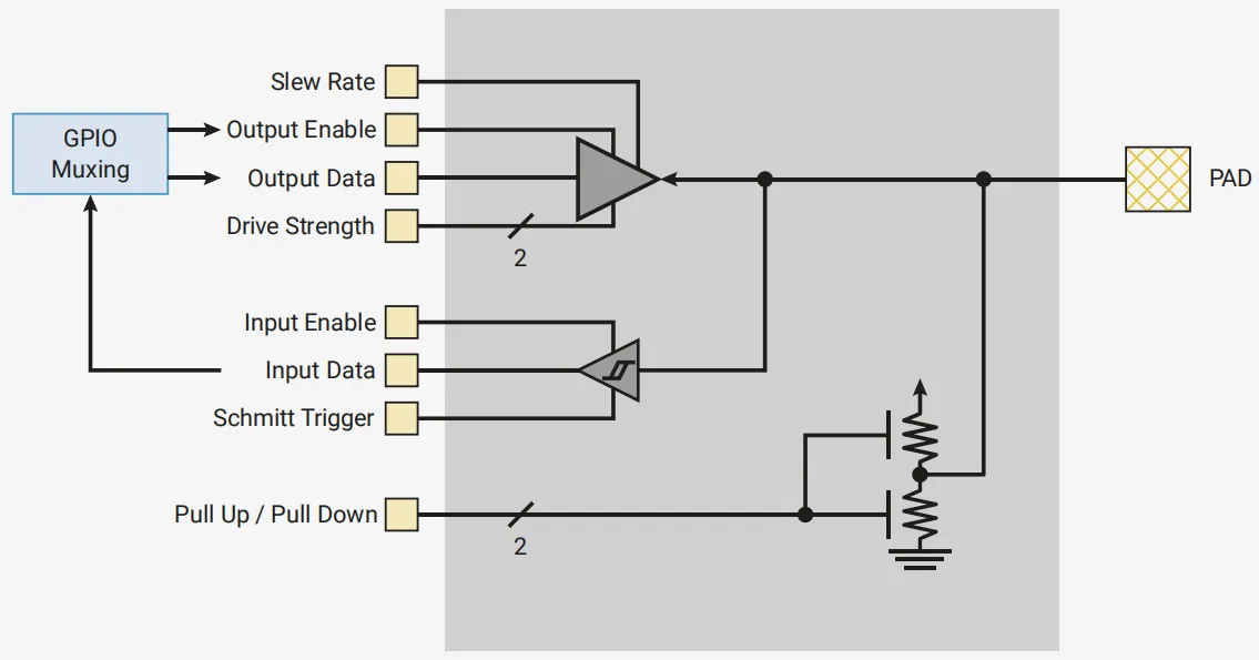
Simply put, "Pads" serve as the "intermediate interface" between GPIO and external circuits. They are responsible for converting the weak signals inside the chip into voltage/current that external circuits can accept, and also protect the chip from being damaged by static electricity.
The "electrical signals" compatible with external circuits that originate from signals inside the chip can be divided into three paths:
- Output link (chip to external):

- From
GPIO Muxing:Output Dataindicates the level (high/low) to be output; Drive Strength: controls the output current level (2mA/4mA/8mA/12mA);Output Enable: Determines whether to output signals externally (On = Output mode, Off = Input mode);Slew Rate: Controls the rate of change of the output level (corresponding to "slow/fast slew rate", to be explained later);- Finally, the signal is transmitted to the external circuit (such as an LED) via
PAD.
- From
- Input link (external to chip):
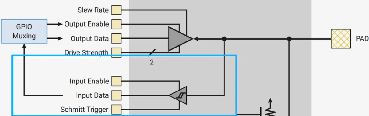
- External signals first pass through
PADto enter; Schmitt Trigger (Schmitt trigger): Makes input signals more "interference-resistant"(for example, when external signals fluctuate slightly, it will not misjudge high and low levels);Input Enable: Determines whether external signals are allowed to enter the chip (when disabled = input buffer is turned off, to be explained later);- Finally
Input Datatransmits the signal to the selected peripheral / SIO.
- External signals first pass through
- Pull-up / Pull-down / Protection Link:
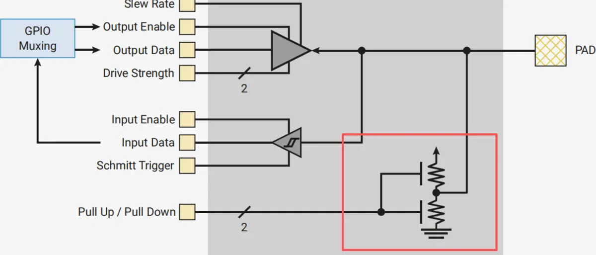
Pull Up / Pull Down: When the GPIO is not outputting (Output Enable is off), it keeps the pin at a fixed high/low level (for example, a key circuit uses "pull-up" to set the pin to a default high level);- The resistors and capacitors nearby: They form an ESD protection circuit to prevent external static electricity from damaging the chip.
The electrical characteristics of "Pads" can be adjusted to meet the requirements of external circuits. The following adjustments are available:
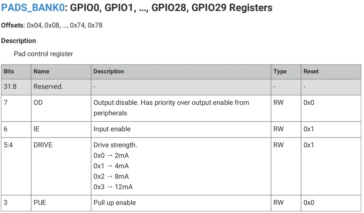
- The output drive strength can be set to 2mA, 4mA, 8mA or 12mA:
- Drive Strength (DRIVE): Select the output current level of the GPIO (2mA/4mA/8mA/12mA) — for example, when connecting an LED, if the current is too low to light the LED, set it to 4mA;
- The output slew rate can be set to slow or fast:
- Fast slew rate: The GPIO pins can switch rapidly between low and high logic levels, making them suitable for high-speed communication (e. g., SPI/UART data transmission), though this will generate more electromagnetic interference (EMI);
- Slow slew rate: The level changes at a low speed, generating less electromagnetic interference, so it is suitable for scenarios sensitive to interference (such as controlling analog circuits).
- Input hysteresis (Schmitt trigger mode) can be enabled:
- Schmitt Trigger (SCHMITT): Makes GPIO more "anti-interference"(it will not misjudge high and low levels when the input signal fluctuates);
- Pull-up or pull-down can be enabled to set the output signal level when the output driver is disabled:
- Pull-up / Pull-down (PUE/PDE): When no device is connected to a GPIO pin, this configuration keeps the pin at a high / low logic level (for example, pull-up resistors are commonly used in key circuits to prevent signal jitter);
- The input buffer can be disabled to reduce the current consumption of the pad when it is unused, unconnected, or connected to an analog signal:
- An input buffer is a circuit that converts external signals into internal signals of a chip;
- If no device is connected to the GPIO, or if it is connected to an analog signal (such as ADC sampling), leaving the buffer enabled will cause unnecessary current waste from "idle operation". Disabling the Input Enable (i. e., turning off the input buffer) can reduce this power consumption.
We can use the following registers to control the Pad:
- VOLTAGE_SELECT Register: I/O Port Input/Output Voltage Type Selection
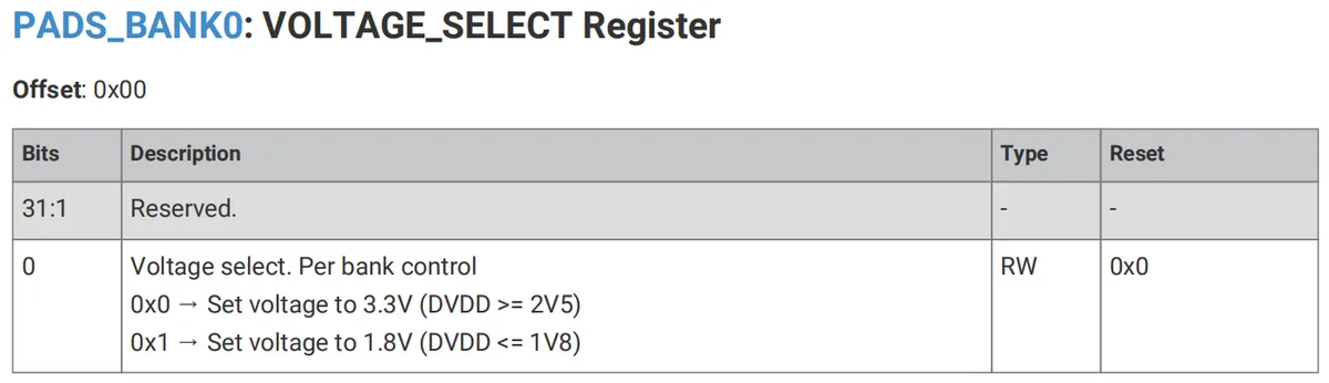
This register is only 1 bit wide and is used to select whether the GPIO uses 3.3V or 1.8V:
- Write
0x0: Use 3.3V (the common voltage for Raspberry Pi Pico); - Write
0x1: Use 1.8V (compatible with low-voltage devices). - GPIOx Registers: function settings including output drive strength, Schmitt trigger mode, pull-up or pull-up enable, output slew rate, etc.

- SWCLK Register/SWD Register: Controls function settings such as output drive strength of SWD pins, Schmitt trigger mode, pull-up or pull-down enable, and output slew rate:
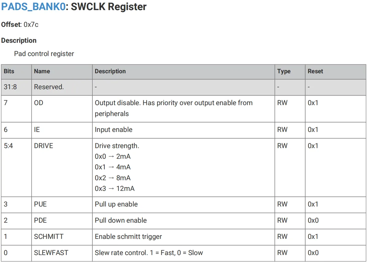
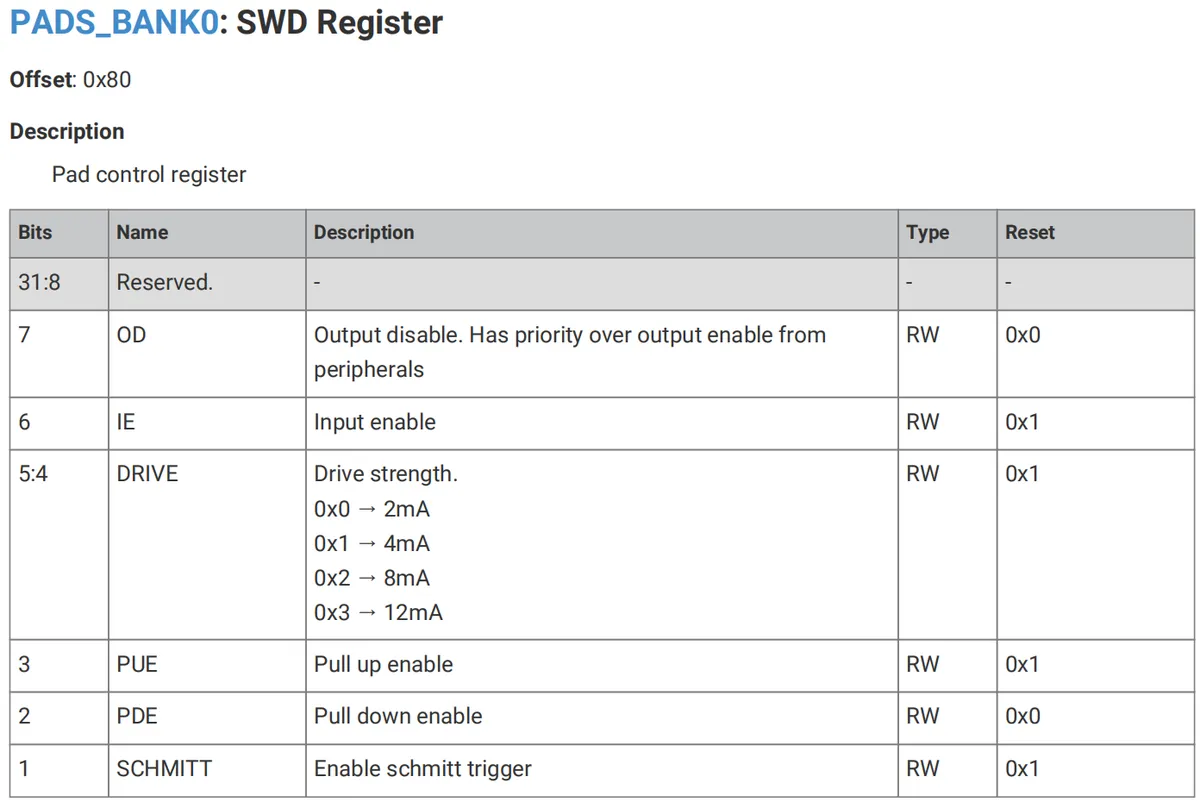

SWCLK is the clock pin of the SWD (Serial Wire Debug) interface on the Pico — the SWD is the interface used for flashing programs and debugging code on the Pico — and the SWCLK Register is a register dedicated to controlling the pad electrical characteristics of this debug pin, whose function is to ensure stable and compatible signal transmission between the SWCLK pin and the external debugger.
Earlier, we covered the function switching and electrical configuration of GPIO. Now, if a GPIO "encounters an event" — say, a key press — how can it actively "alert the CPU to handle it"? This is where GPIO external interrupts come in, which act as the GPIO's "emergency call feature".
The CPU originally executes programs in sequence. When the GPIO triggers an interrupt, the CPU pauses its current task, first handles the "emergency" from the GPIO (for example, turning on an LED when a button is pressed), and then returns to the previous program to continue execution. This enables the Pico to respond to external events in real time without constantly monitoring the GPIO.
GPIO External Interrupt
External interrupt is an internal mechanism for a microcontroller to process external events in real time. When a certain external event occurs, the interrupt system of the microcontroller will force the CPU to suspend the program being executed and turn to process the interrupt event; after the interrupt processing is completed, it returns to the interrupted program and continues execution. The GPIO of the Raspberry Pi Pico can trigger interrupts by four types of events, including rising edge trigger, falling edge trigger, high level trigger and low level trigger.
GPIO external interrupts can be configured into the following four types, and the interrupt type can be modified at any time:
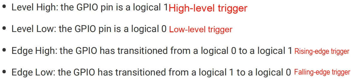
Simply put, GPIO will "place an emergency call" in the following 4 scenarios:
- Level High Trigger: When the GPIO remains at "high level (logic 1)", it continuously calls the CPU (for example, if the GPIO stays at 1 all the time, the interrupt will be triggered continuously);
- Level Low Trigger: Continuously calls the CPU when the GPIO remains at "low level (logic 0)".
- Rising Edge Trigger (Edge High): It triggers the CPU once the instant the GPIO jumps from low level to high level (for example, the exact moment a key changes from "released" to "pressed");
- Falling-Edge Trigger (Edge Low): It triggers the CPU once the instant the GPIO jumps from a high level to a low level (for example, the exact moment a key transitions from being pressed to released).
For the Raspberry Pi Pico, each of its two cores has an independent external interrupt system, which means that the GPIO can "call Core 0" as well as "call Core 1" without interfering with each other.
Taking core 0 as an example, the PROC0_INTEx registers (x: 0~3) are mainly used to enable or disable interrupts, the PROC0_INTFx registers (x: 0~3) are used to force or mask the execution of external interrupts, and the PROC0_INTSx registers (x: 0~3) are used to check the interrupt status after masking or forced execution.
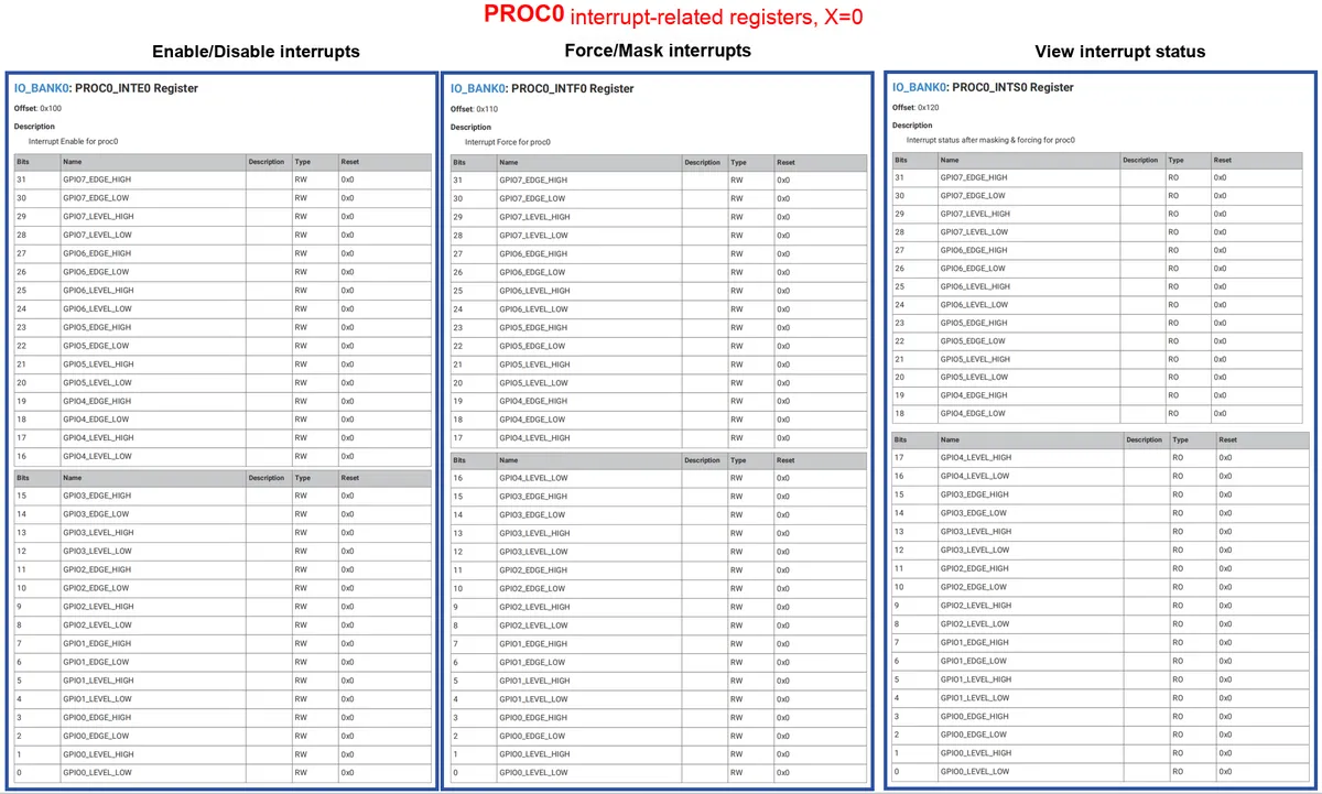
Simply put, it means:
PROC0_INTExRegisters (the "switches" for interrupts): This set of registers is responsible for enabling/disablingGPIOinterrupt calls:Write 1 to the corresponding bit: enable a certain type of interrupt for a specific GPIO(for example, writing 1 to theGPIO0_EDGE_HIGHbit enables the rising-edge trigger ofGPIO0to trigger an interrupt request toCore0);- Write to the corresponding bit
0: to disable this interrupt (equivalent to "hanging up a call of this type").
PROC0_INTFxRegisters (the "manual control keys" for interrupts): This set of registers is designed for "manually simulating / masking interrupts":- Write
1: Force a certain GPIO to trigger an interrupt (equivalent to "manually placing an emergency call once"); - It can also be used to mask unwanted interrupts (i. e., prevent certain calls from disturbing the CPU).
- Write
PROC0_INTSxRegisters (the "caller ID" for interrupts): This set of registers is used to check interrupt status. By reading the bits here, you can find out "which GPIO is triggering which type of interrupt to call the CPU"(for example, if a certain bit is set to1, it means the corresponding GPIO has triggered the corresponding interrupt).
After a GPIO triggers an interrupt, the "call information" will be stored in the INTR register. Please note two key points:
- Edge-triggered interrupt (rising edge / falling edge): This flag can be cleared by "writing
1to the INTR register"(equivalent to "hanging up the call and deleting the message"); - Level-triggered interrupt (high/low level): The status can only be read but cannot be cleared (since the GPIO still maintains the corresponding level, meaning the "call is still ongoing").
Furthermore, there are 4 INTR registers in total, corresponding to different GPIO ranges:
- INTR0: Controls GPIO0 to GPIO7;
- INTR1: Controls GPIO8 to GPIO15;
- INTR2: Controls GPIO16 to 23;
- INTR3: Pins GPIO24 to GPIO29.
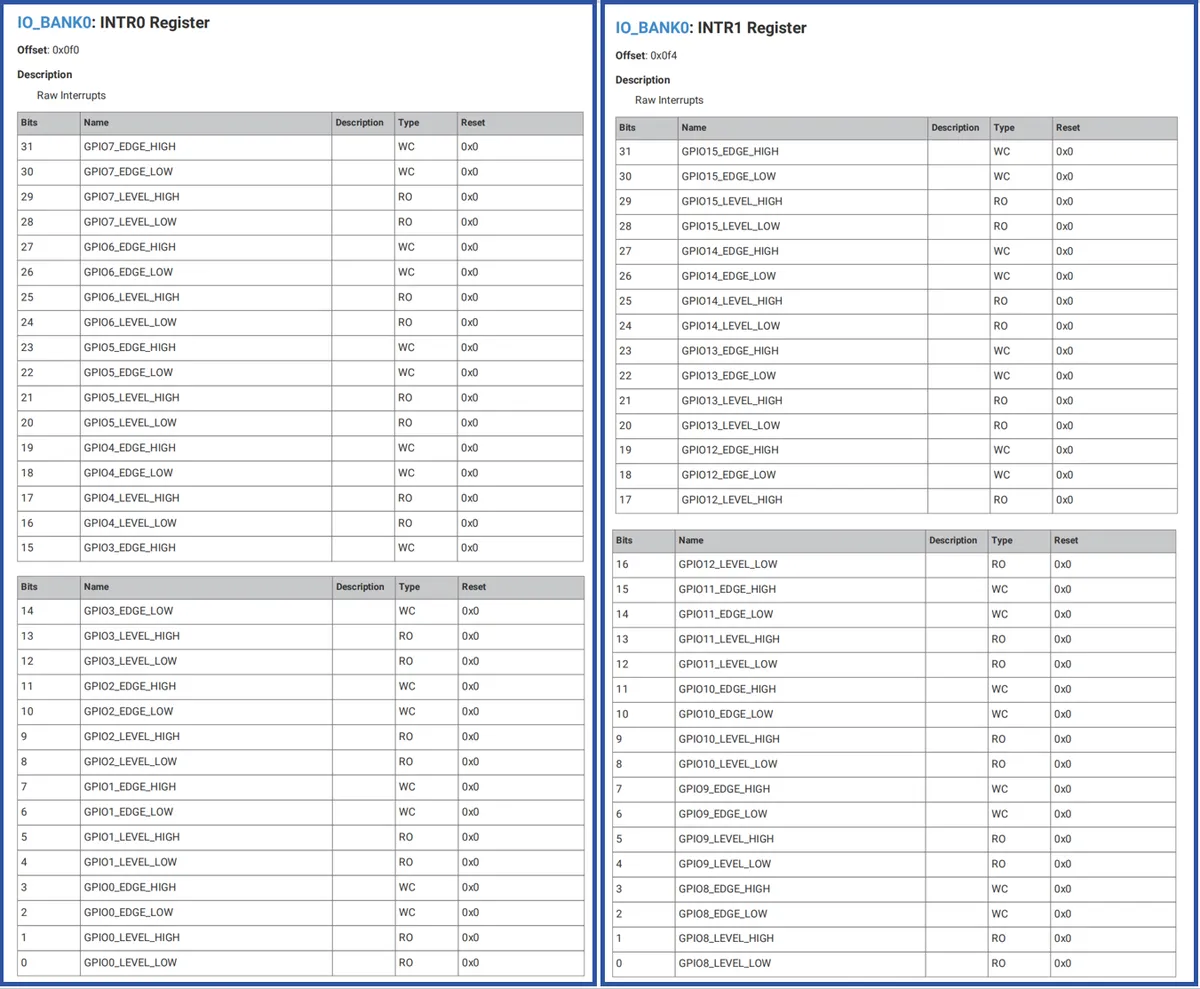
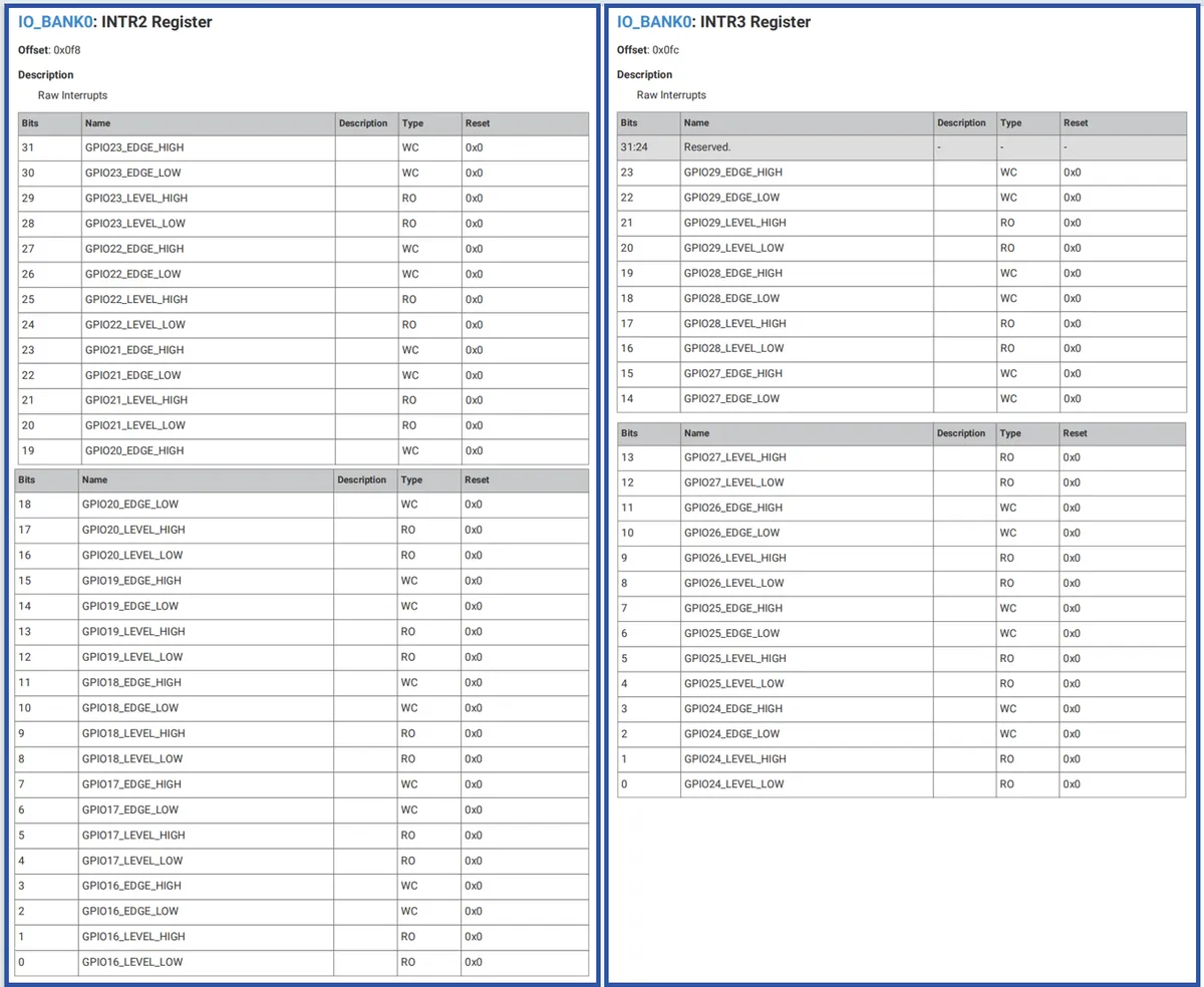
Here, we need to distinguish between raw interrupts and masked interrupts. In the GPIO interrupt system of the Raspberry Pi Pico, an interrupt event goes through two stages from "occurrence" to "being processed by the kernel": "raw event generation" and "event filtering/masking", which correspond to the two core concepts of raw interrupt and masked interrupt. Let's use express delivery as an analogy:
- You (the CPU / core) are working from home, while the courier (the GPIO peripheral) delivers a package (an interrupt event, such as a button press);
- The gate of the residential compound (the interrupt masking / filtering mechanism) determines whether couriers can reach your doorstep.
A raw interrupt (the unfiltered "raw interrupt event") refers to the original event directly generated at the hardware level when the GPIO meets the interrupt trigger conditions (such as a rising edge or a high level), which serves as the "source" of the interrupt:
- Automatically generated by hardware, and not affected by software configurations (interrupt enable, interrupt mask);
- is a "first-hand record" of interruptions, which only records "whether an event has occurred";
- The courier has already arrived at the gate of the residential compound. Regardless of whether you have opened your door or been stopped by the community security guard, the fact that "the delivery has arrived" has genuinely taken place.
Post-mask interrupt (the filtered "kernel-responsive interrupt") refers to the interrupt event that can be perceived and processed by the corresponding kernel after being filtered through configurations such as interrupt enable and interrupt masking based on the original interrupt:
- Dependent on software configuration (e. g., enabling interrupts via
PROC0_INTEx, masking interrupts viaPROC0_INTFx); - is the "valid event" that the kernel truly needs to respond to;
- The courier passed the security check at the residential compound (was not blocked), you also opened the door of your home (interrupt enabled), and finally arrived at your doorstep, so you can actually receive and handle the express delivery.
Put simply, the raw interrupt is the prerequisite for the masked interrupt (if no courier comes, you can never receive the parcel); the masked interrupt is the filtered result of the raw interrupt (the courier may not necessarily reach your doorstep even if they arrive).
Once you understand the raw interrupt and the post-mask interrupt, it becomes very clear that the INTR register and the INTS register are fundamentally different — they act as the "recorders" for these two stages respectively:
| Dimension | INTR register (raw interrupt log) | INTS register (core interrupt to-do list) |
|---|---|---|
| Interrupt types recorded | Records raw interrupts (all GPIO interrupt events that actually occurred) | Records masked interrupts (effective interrupt events the core can perceive) |
| Scope | Global (not specific to Core0/Core1; shared by all cores) | Core-specific (e.g., PROC0_INTSx belongs only to Core0) |
| Affected by configuration? | No (recorded whenever an interrupt occurs, regardless of whether it is enabled or masked) | Yes (recorded only if the interrupt is enabled and not masked) |
| Operation | Edge-triggered bits can be cleared by writing 1 (clears processed raw log entries); level-triggered bits are read-only | Read-only (can only view the core's pending interrupt status; cannot modify) |
| Analogy | All parcel records at the neighborhood parcel station (whether or not the parcels have been picked up) | The list of parcels waiting for pickup at your door (only parcels that can be delivered to your home are listed here) |
As a practical example, when GPIO0 triggers a rising-edge interrupt:
- Original interrupt occurs: the bit corresponding to GPIO0 in the INTR0 register will be set to 1 (recording that "the courier has arrived at the residential complex");
- If you have enabled the rising-edge interrupt for GPIO0 via
PROC0_INTE0and it is not masked byPROC0_INTF0:- Interrupt after masking generation: The bit corresponding to GPIO0 in the PROC0_INTSx register will be set to 1 (to record "the courier has arrived at your doorstep");
- Core0 will sense this interrupt and suspend the current program for processing;
- After you handle the interrupt, write 1 to the GPIO0 bit of the INTR0 register to clear this original record (equivalent to "confirming that the express delivery has been signed for");
- If you have previously disabled the interrupt enable function of GPIO0:
- The INTR0 register will still be set to 1 (the original interrupt remains);
- The PROC0_INTSx register will not be set to 1 (no interrupt will be generated after being masked);
- Core0 will not perceive this interrupt at all, as if it had never occurred.
1.3 Overview of GPIO on Raspberry Pi Pico
1.3.1 Introduction to IO Port Functions of Raspberry Pi Pico
Simply put, the Raspberry Pi Pico has 26 usable pins led out to the external header pins. GPIO 0 to GPIO 22 support digital signal input and output (adopting the TTL level standard: the high level is around 3.3V and the low level is around 0V), while GPIO 26 to 28 are analog signal input pins.
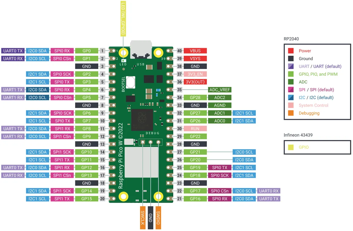
By default, GPIO 0 to 25 are bidirectional digital pins (usable as input or output) in pull-down state, with a default drive current of 4 mA; GPIO 26 to 29 can be used as analog inputs or digital IOs, with a default drive current of 4 mA.
Besides, Raspberry Pi Pico exposes the RUN pin, which can only be used as a digital signal input. By default, the RUN pin is in a pulled-up state, and if the RUN pin is pulled low, the chip will reset and restart.
1.3.2 Electrical Parameters of GPIO Ports
The following electrical parameters are the "hardware usage rules" for the Raspberry Pi Pico GPIO — which is equivalent to the "safe operation manual" for GPIO: failure to comply will either result in abnormal GPIO operation (such as erratic signal fluctuations) or directly burn out the hardware.
1.3.2.1 Maximum and minimum rated voltages

This set of parameters represents the physical damage threshold of the GPIO, which determines the voltage range that the GPIO can withstand:
| Parameter | Range | Actual effect |
| I/O Supply Voltage (IOVDD, IO supply voltage) | -0.5 ~ 3.63 V | Upper voltage limit for powering the GPIO: for example, if you power the Pico's IO pins with 5V, exceeding 3.63V will directly burn out the GPIO. |
| Voltage at IO (VPIN, IO pin voltage) | -0.5 ~ IOVDD+0.5 V | Maximum voltage an IO pin can withstand: for example, when IOVDD is 3.3V, VPIN must not exceed 3.8V, otherwise the pin will be damaged by voltage breakdown. |
1.3.2.2 Digital IO Parameters
When IOVDD = 3.3V:
- For digital inputs:
- The high and low level range of digital input refers to the voltage interval within which GPIO can correctly identify signals, which directly affects signal reliability;
- High level: The voltage ranges from 2 V to 3.6 V. If the input voltage is lower than 2 V (e. g., a sensor output of 1.8 V), the GPIO will misidentify a signal that should be a high level as a low level;
- Low level: The voltage ranges from -0.3 V to 0.8 V. If the input voltage is higher than 0.8 V (for example, the voltage is 1 V after the key is released), the GPIO will misidentify the signal that should be a low level as a high level.
- For digital outputs:
- The high and low levels of the digital output plus the drive current constitute the upper limit of the GPIO’s capability to drive external devices;
- High level: The voltage ranges from 2.62 V to 3.3 V, with a maximum drive current of 12 mA. For example, it can properly drive a 5 mA LED, but will fail to "power" a 20 mA device (the device will not function, and the GPIO may even be burned out);
- Low level: Voltage ranges from 0 to 0.5 V, with a maximum drive current of 12 mA
Also note that the total drive current of all GPIO pins should be less than 50 mA (for example, connecting 5 LEDs of 10 mA at the same time is just within the limit, while connecting 6 will cause overload and affect the power supply stability of Pico).
The resistance values of the internal pull-up and pull-down resistors range from 50k to 80k ohms, and this parameter affects the stability of the input signal. For example, when an internal pull-up resistor is used in a key circuit, a resistance within this range can keep the GPIO stably at a high level when the key is released; if the resistance is too small, it will consume extra power, while if it is too large, the anti-interference capability will become weaker.
1.3.2.3 Analog IO Parameters
The input voltage range of the ADC is from 0 to the supply voltage of the ADC_AVDD analog-to-digital converter, and the minimum internal input impedance of the ADC is 100 kΩ:
- ADC is a module that "converts analog voltage to digital signals", and its input voltage must stay within the specified range. For example, when ADC_AVDD is 3.3V, an input voltage of 4V will lead to incorrect sampling results and may even burn out the ADC;
- The internal input impedance of an ADC can be understood as the "internal equivalent resistance" of the ADC (the input impedance of Pico's ADC is ≥100kΩ), which acts as the "internal resistance" when the ADC receives signals. When you connect an analog device to the ADC pin, the ADC's input impedance (R_ADC) and the output impedance of the external device (R_ext) are connected in series, and they will divide the "true output voltage of the analog device (V_source)". That is, the final voltage actually input into the ADC (V_ADC) is the result after voltage division. It is recommended that the output impedance of the connected external analog device be "much smaller than 100kΩ"(usually recommended to be ≤10kΩ), so that the influence of voltage division is negligible, and the ADC can sample a voltage close to the true value.
2. Software Control Method
General Purpose Input/Output (GPIO) is mainly initialized and controlled via the Pin class in the machine module. The Pin class is typically associated with physical GPIO pins that can drive output voltages and read input voltages. It provides methods to control the pin mode (such as IN, OUT) as well as to get and set digital logic levels. For analog control of pins, please refer to the ADC class.
2.1 Constructor of the machine.Pin Class
The constructor of the machine.Pin class is as follows:
class machine.Pin(id, mode=- 1, pull=- 1, *, value, drive, alt)
The parameters are defined as follows:
- id is mandatory and can be any object. Possible value types include: int (internal Pin identifier), str (Pin name), and tuple ([port, pin] pair)
- mode specifies the pin mode, which can be one of the following:
- Pin.IN - The pin is configured as an input. When regarded as an output, this pin is in a high-impedance state.
- The high-impedance state is neither a high level nor a low level; its extremely high impedance is equivalent to an open circuit. A pin in the high-impedance state exhibits uncertain voltage characteristics externally. Setting a port to the high-impedance state is equivalent to disconnecting that port from the circuit, and it will not affect other circuits.
- High-impedance state is commonly used in bus structures.
- Pin.OUT - The pin is configured as a (normal) output, i. e., a push-pull output.
- The push-pull output can truly output high level and low level, and has driving capability under both voltage levels.
- For digital signal transmission, when the previous stage acts as an output, it is optimal for the next stage to be in a high-impedance state, as this allows signal transmission to be achieved solely via voltage transfer. If the internal resistance of the load is low, the IO port will be required to output a relatively large current.
- Pin.OPEN_DRAIN - The pin is configured as an open-drain output
- The working principle of open-drain output is as follows: when the output value is set to 0, the pin is at a valid low level; when the output value is 1, the pin enters a high-impedance state. That is, it has no driving capability at high level, and an external pull-up resistor is required to realize external driving.
- It is commonly used in scenarios such as level conversion, implementing the "wired-AND" function, and reducing the driving current inside an IC.
- Pin.ALT - The pin is configured to perform a port-specific alternate function. For pins configured in this manner, all other pin methods (except Pin.init ()) are not applicable (calling them will result in undefined or hardware-specific behavior)
- Not all ports implement this mode.
- Pin.ALT_OPEN_DRAIN - Same as Pin.ALT, but the pin is configured as open-drain. Not all ports implement this mode.
- Pin.ANALOG - The pin is configured as an analog signal input terminal
- Pin.IN - The pin is configured as an input. When regarded as an output, this pin is in a high-impedance state.
- pull Check whether the specified pin is connected to a (weak) pull-up resistor, and the value can be one of the following:
- None - No pull-up or pull-down resistor, the pin is in a floating state
- In practical applications, it is not recommended to leave the pins floating, as they are susceptible to interference.
- Pin.PULL_UP - Enable pull-up resistor
- An uncertain signal is clamped to a high level through a resistor, which also functions as a current limiter.
- Pin.PULL_DOWN - Enable pull-down resistor
- Pull an uncertain signal down to a low level via a resistor, which also functions as a current limiter.
- None - No pull-up or pull-down resistor, the pin is in a floating state
- value - Only valid for Pin.OUT and Pin.OPEN_DRAIN modes. If specified, it sets the initial output pin value; otherwise, the state of the pin peripheral remains unchanged
- drive - Specifies the output power of the pin, which can be one of the following: Pin.LOW_POWER, Pin.MED_POWER, or Pin.HIGH_POWER. The actual current driving capability depends on the port. Not all ports support this parameter.
- alt - Assigns an alternate function to the pin; the available values depend on the port.
This parameter is only valid for Pin.ALT and Pin.ALT_OPEN_DRAIN modes. It can be used when a pin supports multiple alternate functions; if a pin only supports one alternate function, this parameter is not required. Not all ports implement this parameter.
As mentioned above, the Pin class allows setting alternate functions for a specific pin, but it does not specify any further operations on such pins. Generally, when configuring a peripheral that requires GPIO, for example, when initializing a UART, the constructor of the corresponding pin will be automatically called for initialization.
2.2 Other Methods of the machine.Pin Class
Method | Description |
Pin.init (mode=- 1, pull=- 1, *, value, drive, alt) | Reinitialize the pin with the given parameters. Only the specified parameters will be configured, while the status of other pin peripherals will remain unchanged. |
Pin.value([x]) | This method allows setting and getting the value of the pin. Depending on whether x is provided, the parameters are as follows:
When setting a value, this method returns None. |
Pin.__call__([x]) | Pin objects are callable. The `call` method provides a quick shortcut to set and get the value of a pin. It is equivalent to `Pin.value ([x])`. |
Pin.on() | Set the pin to high-level output. |
Pin.off() | Set the pin to low-level output. |
Pin.irq(handler=None, trigger=Pin.IRQ_FALLING | Pin.IRQ_RISING, *, priority=1, wake=None, hard=False) | A function for configuring external interrupts for GPIO pins. When the pin modes differ, the trigger sources of external interrupts also vary:
The parameters of the Pin.irq method are defined as follows:
This method returns a callback object. |
Pin.low() | Set the pin to low-level output. |
Pin.high() | Set the pin to high-level output. |
Pin.mode([mode]) | Gets or sets the pin mode. |
Pin.pull([pull]) | Gets or sets the pull-up state of the pin. |
Pin.drive([drive]) | Get or set the pin drive strength. The Raspberry Pi Pico does not support the configuration of drive strength. |
2.3 Constructor method of the machine.Signal class
The Signal class is a further encapsulation of the Pin class. With the Signal class, we can configure whether to invert the logic of a specific pin (simply put, originally we set high level as logic 1 and low level as logic 0; after inversion, we can set high level as logic 0 and low level as logic 1), thus logically separating the control from the actual physical quantity.
For example, in the following two schemes of MCU controlling LED with different circuit connections, if you directly use Pin for control, you need to use respectively: led_pin (1), led_pin (0) to turn on the LED.
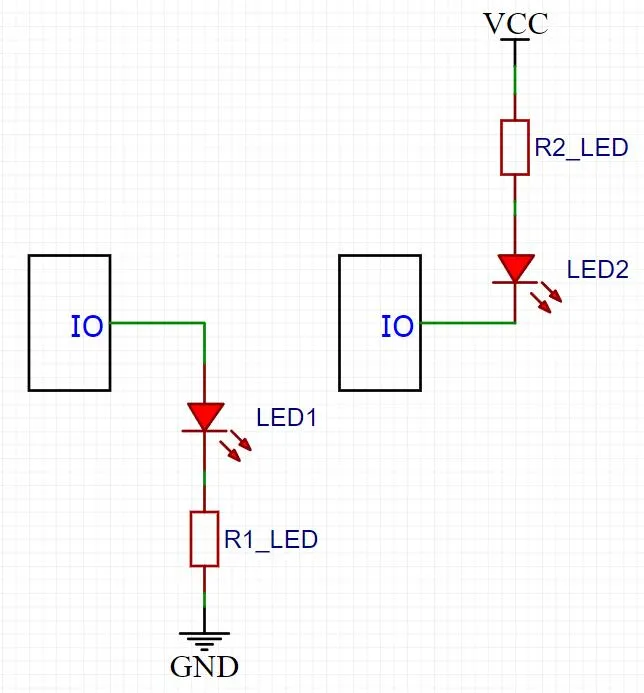
After using the Signal class, we can use the same method (e. g., led_pin (1)) to control the lighting of the LED without paying attention to the differences in external connection circuits. By using the Signal class, we can ignore the specific physical distinction between high and low levels, so that our program only needs to modify some parameters in the Signal class to run without difference on most circuit boards with different connection modes of external device circuits without generating BUGs.
The Signal class is applicable to the following application scenarios:
- Output high and low levels to control external sensors, for example: implementing PWM via software to drive motors, buzzers or LEDs, controlling the on/off status of digital tubes, and controlling the opening and closing of relays
- Read the high and low levels sent by external sensors, for example: reading whether a key is pressed, and the digital outputs of reed switches, infrared sensors, humidity/flame sensors
There are two types of constructors for Signal:
- By passing the required Pin parameters directly to the Signal constructor, there is no need to create an intermediate Pin object. It should be noted that this method is not necessarily applicable to all development boards!
class machine.Signal(pin_arguments..., *, invert=False)
The parameters are defined as follows:
- pin_arguments are the same arguments that can be passed to the Pin constructor function
- invert If set to true, the signal will be inverted (active low)
- By wrapping the existing Pin object (this method is applicable to all development boards):
class machine.Signal(pin_obj, invert=False)
The parameters are defined as follows:
- pin_obj is the existing Pin object
- invert If set to true, the signal will be inverted (active low)
2.4 Other Methods of the machine.Signal Class
Method | Description |
Signal.value([x]) | This method allows setting and getting the value of a signal, depending on whether an argument x is provided:
The correspondence between a signal being active and the actual logic level on the underlying pin depends on whether the signal is inverted (active-low): for non-inverted signals, the active state corresponds to logic 1 and the inactive state corresponds to logic 0; for inverted signals, the active state corresponds to logic 0 and the inactive state corresponds to logic 1. |
Signal.on() | activation signal |
Signal.off() | Deactivation Signal |
3. Application Examples
3.1 GPIO Read/Write Example
In the following experiment, we use Fengya No. 1 Board - Universal Compatible Expansion Board.
In the following code, we first import the Pin class and the time class. In the initialization configuration, we set GPIO 22 as the button input pin, set GPIO 25 as the LED output pin, and enable the pull-down resistor.
In the main loop, continuously detect whether the key is pressed:
- If the button is not pressed: do not perform any operation.
- If the key has been pressed: In the hardware circuit, when the key is pressed, the GPIO pin reads a low level (0). After detecting the key press, delay for 50 milliseconds (
time.sleep_ms (50)) to perform key debouncing- If the current state of the
LEDis off, switch to light, end point output"The LED is ON" - If the current state of the
LEDis on, switch to off, end point output"The LED is OFF"
- If the current state of the
The 50ms delay here is mainly due to the contact bounce phenomenon that occurs when a key is closed and opened, as shown in the figure below:
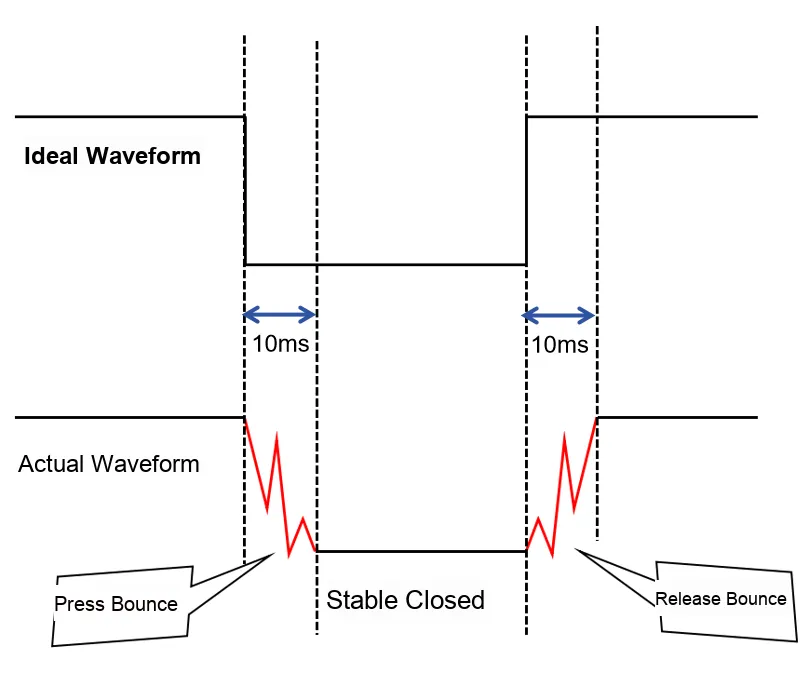
The actual waveform has a jitter of 50ms around the moment when the key is pressed, so here we skip the jitter area by delaying for 50ms to obtain the level in the intermediate stable area.
The sample code is as follows, located in the folder of the supporting materials: elegance-devkit v1\Demo\01 GPIO_ReadWrite:
# Python env   : MicroPython v1.23.0
# -*- coding: utf-8 -*-
# @Time    : 2024/6/12 1:34 PM
# @Author  : Li Qingshui
# @File    : main.py
# @Description : GPIO read/write experiment: drive the onboard LED and read a button

# ======================================== Import Modules ========================================

# Hardware-related modules
from machine import Pin
# Time-related modules
import time

# ======================================== Global Variables ============================================

# Initialize the LED state to off (False)
led_state = False

# ======================================== Functions ============================================

# ======================================== Custom Classes ============================================

# ======================================== Initialization ==========================================

# Power-on delay of 3 s
time.sleep(3)
# Print debug message
print("FreakStudio: Using GPIO to control LED and read KEY")

# Note that the constructor of the Pin class in MicroPython does not support keyword arguments, only positional arguments
# Therefore, defining KEY as follows will produce an error
# TypeError: function missing 1 required positional arguments
# key = Pin(id = 2, mode = Pin.IN, pull = Pin.PULL_DOWN)

# Set GPIO 22 as the button input pin
KEY = Pin(22, Pin.IN)
# Set GPIO 25 as the LED output pin, pull-down resistor enabled
LED = Pin(25, Pin.OUT, Pin.PULL_DOWN)

# ========================================  Main Program  ============================================

# Loop to detect whether the button is pressed
while True:
    # KEY pin press detected
    if KEY.value() == 0:
        # Button debounce: delay 50 ms to skip the bouncing period
        time.sleep_ms(50)
        # Make sure the button is still pressed
        if KEY.value() == 0:
            # Toggle the LED state
            led_state = not led_state
            # Set the LED on or off according to the state variable
            if led_state:
                LED.on()
                print("The LED is ON")
            else:
                LED.off()
                print("The LED is OFF")
            # Wait for the button to be released (avoid detecting repeated presses)
            while KEY.value() == 0:
                pass
It should be noted here that MicroPython does not support keyword arguments when passing parameters to the constructor of the Pin class, and only supports positional arguments, so the following definition of KEY will throw an error TypeError: function missing 1 required positional arguments:
KEY = Pin(id = 2, mode = Pin.IN, pull = Pin.PULL_DOWN)Burn the above code into MicroPython, and you can observe the experimental phenomenon:
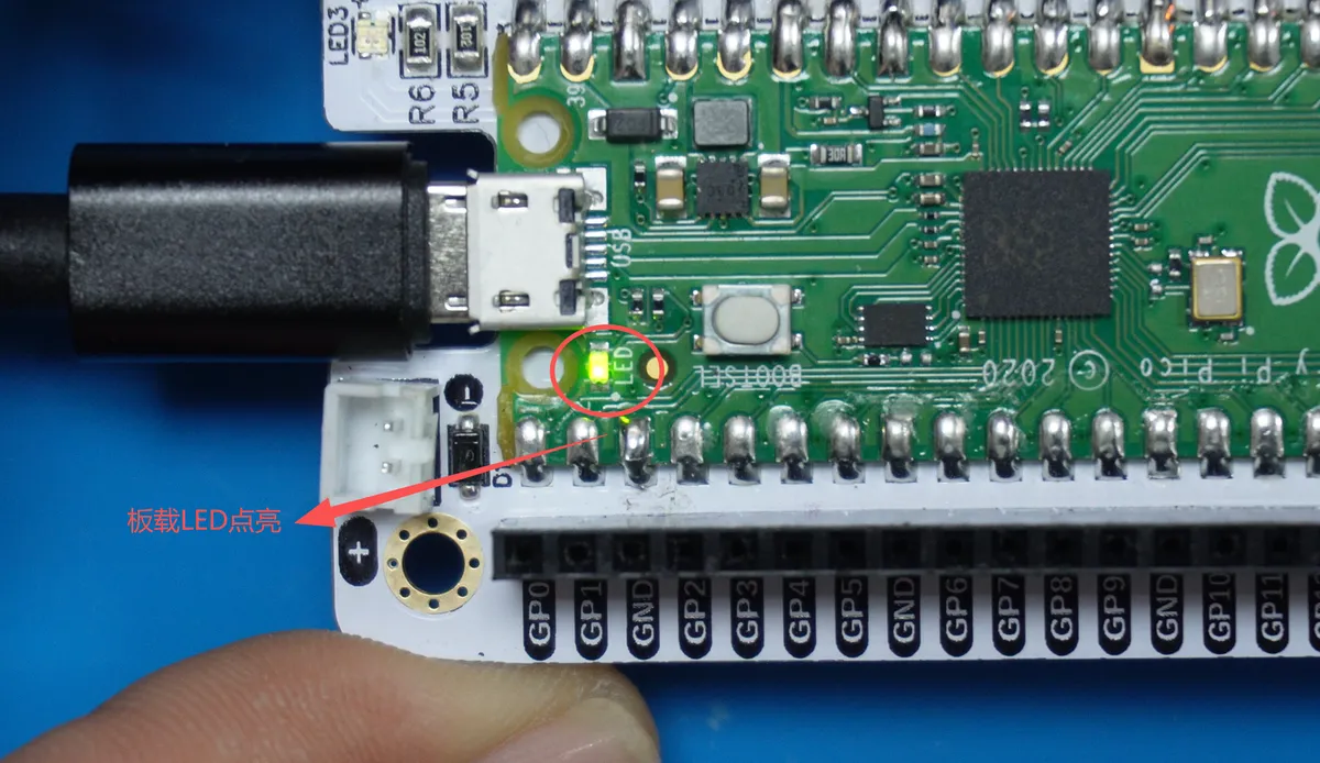
When the key is pressed for the first time, toggle led_state to True, the LED will light up and the terminal outputs the following:

When the button is pressed a second time, toggle led_state to False, the LED turns off and the terminal outputs the following:

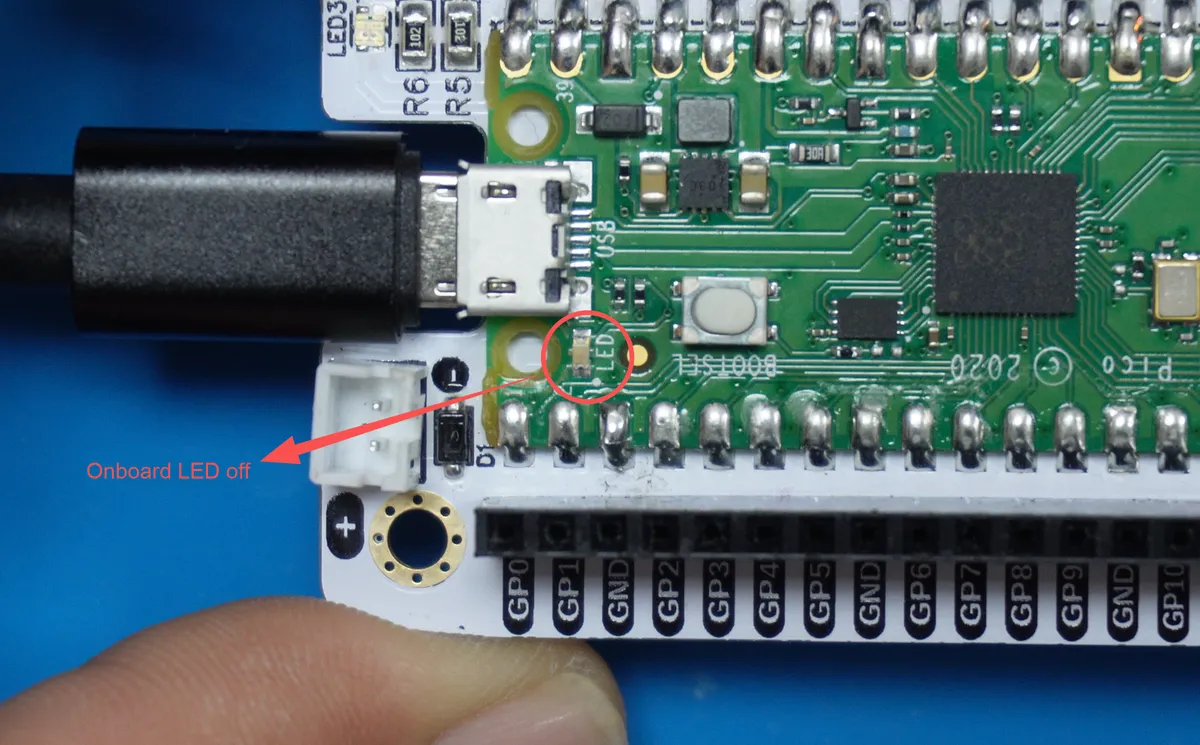
After that, each time a key is pressed, the status of the LED toggles alternately between on and off.
3.2 GPIO External Interrupt Example
In the following experiment, we use Fengya No. 1 Board - Universal Compatible Expansion Board.
When using external interrupts, we need to specify which pins are used for interrupts, the conditions for triggering the interrupts, and the operations to be performed after the interrupts are responded to.
In the following code, we set GPIO22 as a key input pin with pull-up resistor enabled, configure GPIO22 to generate a falling-edge triggered interrupt, and execute the handle_interrupt function after the interrupt is responded to, toggle the value of led_state and the status of the LED, and print the LED status information during the interrupt.
In the main program's while loop, debug information is output "Waiting for button press. ..". The main loop will not interfere with the execution of interrupts, which are triggered by hardware and respond in real time.
The sample code is located in the folder of the supporting materials as follows: elegance-devkit v1\Demo\02 GPIO_EXTI:
# Python env   : MicroPython v1.23.0
# -*- coding: utf-8 -*-
# @Time    : 2024/6/14 11:10 AM
# @Author  : Li Qingshui
# @File    : main.py
# @Description : GPIO external interrupt experiment: press the button to toggle the LED on/off

# ======================================== Import Modules ========================================

# Hardware-related modules
from machine import Pin
# Time-related modules
import time

# ======================================== Global Variables ============================================

# LED state flag: True means on, False means off
led_state: bool = False

# ======================================== Functions ============================================

def handle_interrupt(pin: Pin) -> None:
    """
    Callback function for the GPIO external interrupt, used to toggle the LED on/off state.

    After the interrupt is triggered, button debouncing is performed first. After confirming the button is still pressed,
    the LED is toggled on or off according to its current state, and the state information is printed.

    Args:
        pin (Pin): The GPIO pin instance that triggered the interrupt.

    Returns:
        None
    """
    # Declare global variables
    global LED
    global led_state

    # Debounce: delay 50 ms
    time.sleep_ms(50)

    # Confirm again that the button is still pressed (GPIO pin level is low)
    if pin.value() == 0:
        # Toggle the LED state
        led_state = not led_state
        if led_state:
            # LED on
            LED.on()
            print("The LED is ON")
        else:
            # LED off
            LED.off()
            print("The LED is OFF")

# ======================================== Initialization ==========================================

# Power-on delay of 3 s
time.sleep(3)
# Print debug message
print("FreakStudio: Using GPIO EXTI interrupt to toggle LED")

# Set GPIO 22 as the button input pin, pull-up resistor enabled
KEY = Pin(22, Pin.IN, Pin.PULL_UP)
# Set GPIO 25 as the LED output pin, pull-down resistor enabled
LED = Pin(25, Pin.OUT, Pin.PULL_DOWN)

# Configure the KEY interrupt: the callback is handle_interrupt, triggered on the falling edge
KEY.irq(handler=handle_interrupt, trigger=Pin.IRQ_FALLING)

# ======================================== Main Program ============================================

# Main loop: output button state information while the program is idle
while True:
    # Wait for the interrupt to trigger, print debug information
    print("Waiting for button press...")
    time.sleep(1)
Burn the code and open the terminal, then you can see the following output in the terminal when no button is pressed:
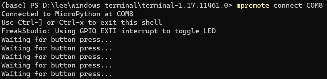
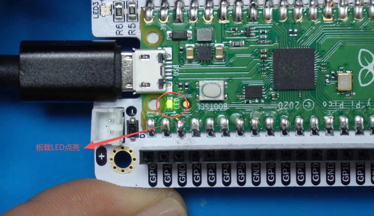
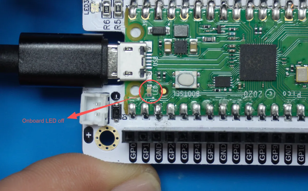
When the key is pressed, the LED lights up; when pressed again, the LED turns off. The experimental phenomenon is similar to that of the GPIO read-write routine in Section 3.1.
When the button is pressed for the first time:
When the button is pressed for the second time:
Here, we have added type annotations to the code and complied with the PEP8 specification. The so-called type annotation is a mechanism in Python used to specify the data types of variables, function parameters and return values. Simply put, it explicitly tells others or program tools in the code what type a certain variable, function parameter or return value is (such as integer, string, list, etc.). It is like making notes for variables and functions. For example, if you define a function that receives a number but someone passes in a text, the type annotation can warn you in advance where the problem is.
For more information on type annotations, you can refer to the following articles:
Meanwhile, all our code complies with the PEP8 specification, PEP8 is a style guide for the Python programming language, whose full name is "Python Enhancement Proposal 8"(Python Enhancement Proposal No. 8). It is a document that specifies the best practices and formatting requirements for writing Python code. Simply put, it is a set of code writing rules, similar to the formatting requirements for writing an essay.It teaches you how to format your code to be neater and more readable, for example, using lowercase letters with underscores for variable names, leaving two blank lines between functions, keeping each line of code under 79 characters, and so on. Its goal is to make the code everyone writes have a consistent style, look more comfortable, and be easier to maintain and collaborate on at the same time.
For more details about the PEP8 style guide, please refer to the following article:
3.3 Signal Class Routines
In the following experiment, we need to insert the Fengya No. 1 Board - Colorful Touch Expansion Board into the Fengya No. 1 Board - Universal Compatible Expansion Board:
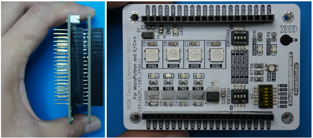
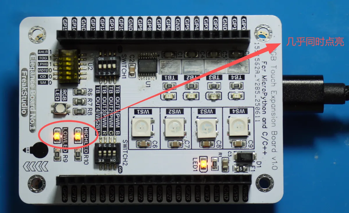
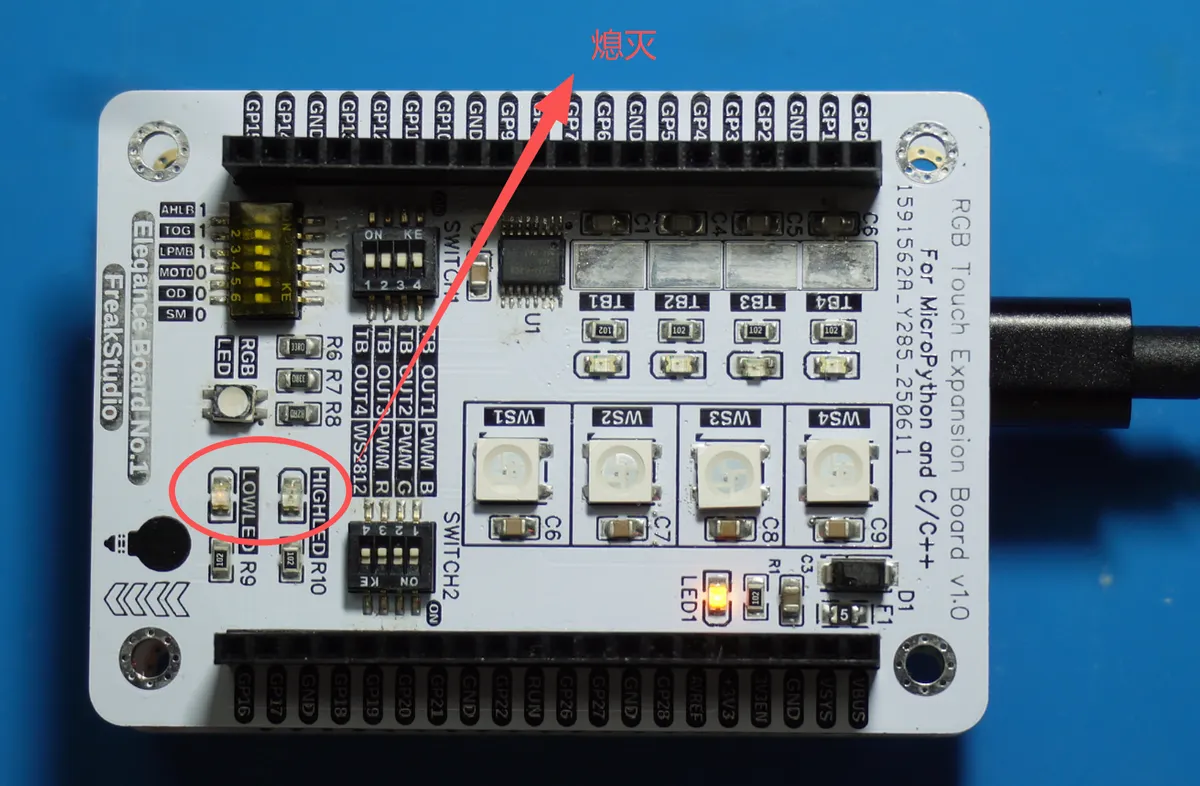
In the following routine, we use the Signal class to control two LEDs connected to different circuits, where GP17 is connected to an LED whose cathode is tied to ground, so the corresponding GPIO lights it up by outputting a high level; while GP16 is connected to an LED whose anode is tied to + 3V3, so the corresponding GPIO lights it up by outputting a low level. We use the Signal class to wrap the existing Pin object, ultimately achieving control over the LED via the same method.
The code is as follows:
# Python env   : MicroPython v1.23.0
# -*- coding: utf-8 -*-
# @Time    : 2024/6/21 10:32 AM
# @Author  : Li Qingshui
# @File    : main.py
# @Description : Signal class experiment: control two LEDs connected with different circuits

# ======================================== Import Modules ========================================

# Hardware-related modules
from machine import Pin, Signal
# Time-related modules
import time

# ======================================== Global Variables ============================================

# ======================================== Functions ============================================

# ======================================== Custom Classes ============================================

# ======================================== Initialization ==========================================

# Power-on delay
time.sleep(3)
# Print debug information
print("FreakStudio : Signal Class Test")

# Set GPIO 17 as the LED1 (common anode) output pin, pull-down resistor enabled
LED1_Pin = Pin(17, Pin.OUT, Pin.PULL_DOWN)
# Set GPIO 16 as the LED2 (common cathode) output pin, pull-down resistor enabled
LED2_Pin = Pin(16, Pin.OUT, Pin.PULL_DOWN)

# ========================================  Main Program  ============================================

# Without the Signal class, using the Pin class directly requires accounting for differences in the external circuits, and different levels are needed to turn on the LEDs
# LED1 turns on with a high-level input
LED1_Pin.value(1)
# LED2 turns on with a low-level input
LED2_Pin.value(0)

# Wrap the existing Pin objects with the Signal class
# LED1_Pin is not inverted: high level = 1, low level = 0
LED1 = Signal(LED1_Pin, invert=False)
# LED2_Pin is inverted: high level = 0, low level = 1
LED2 = Signal(LED2_Pin, invert=True)

# Now one method can turn on both LEDs
LED1.on()
LED2.on()

# Wait for 5 s
time.sleep(5)

# Get the signal state
print("LED 1 value :", LED1.value())
print("LED 2 value :", LED2.value())

# Get the pin state
print("LED1_Pin value :", LED1_Pin.value())
print("LED2_Pin value :", LED2_Pin.value())

# Turn off both LEDs
LED1.off()
LED2.off()

# Wait for 1 s
time.sleep(1)

# Get the signal state
print("LED 1 value :", LED1.value())
print("LED 2 value :", LED2.value())

# Get the pin state
print("LED1_Pin value :", LED1_Pin.value())
print("LED2_Pin value :", LED2_Pin.value())
Burn the code, open the terminal, and use mpremote to connect to the Raspberry Pi Pico, you will see the following output:
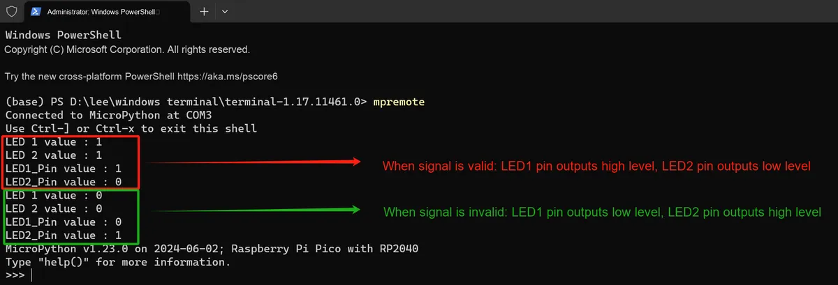
We can see that on the Elegance No. 1 Board - Colorful Touch Expansion Board, the HIGHLED and LOWLED are lit up simultaneously first, and then turned off at the same time:
3.3 Application Experiment.mp4 19.5 MB
3.4 Stepper Motor Control via GPIO
3.4.1 Basic Knowledge of Stepper Motor
A stepper motor is a special type of electric motor that converts input electrical pulse signals into discrete changes in angle or position, thereby enabling precise angle control. Stepper motors mainly have the following characteristics:
- Stepper operation: A stepper motor controls the power-on sequence of its coils to drive the rotor to rotate at a fixed angle (step angle), thereby achieving position control. Common step angles include 1.8°, 0.9°, etc.
- High positioning accuracy: The stepper motor can precisely control the rotation angle with high positioning accuracy, generally within ±3%.
- Open-loop control: The position control of the stepper motor is realized through open-loop control, which enables precise control without the need for feedback signals.
- High torque: The stepping motor delivers relatively high output torque at low speeds, making it suitable for applications that require driving heavy loads.
- Quick response: The stepping motor features fast start-up, stop and steering speeds, with rapid response.
Stepper motors are widely used in various automated equipment, such as printers, computer numerical control machine tools, robots, 3D printers, etc. , and are an ideal choice for achieving precise position control. By controlling the frequency and sequence of pulse signals, the speed, angle and direction of the motor can be accurately controlled.
Here, the motor model we use is 28BYJ-48 5-wire 4-phase stepper motor:
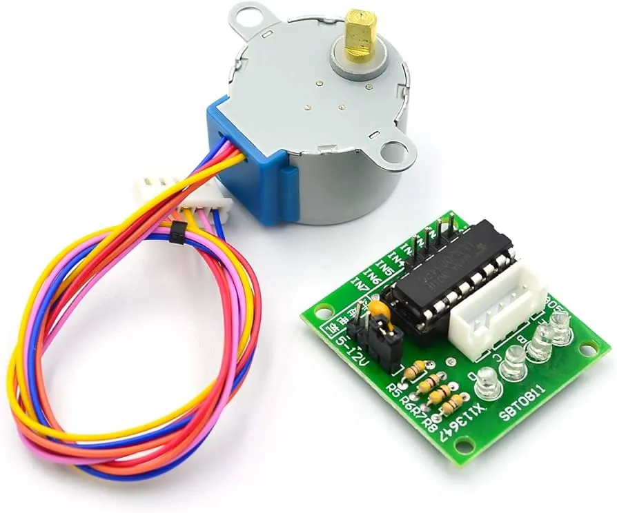
It has the following main features:
- Small dial-type structure: The 28BYJ-48 is compact in size, with a diameter of only 28mm and a length of approximately 34mm.
- Low-voltage power supply: The operating voltage ranges from 5V to 12V, which can be directly connected to low-voltage circuits such as microcontrollers.
- Low power consumption: The typical operating current is only 12-14mA, which is extremely energy-efficient.
- High torque: The output torque can reach up to 34.3 mN·m, which is sufficient to drive various small loads.
- Low speed with high precision: the step angle is 0.0625°, which can reach up to 4096 steps per revolution, featuring extremely high precision.
- 5 leads: including 4 wires for the two-phase windings and 1 common ground wire.
This 28BYJ-48 stepper motor is widely used in various small electromechanical devices, such as door locks, toys, automation equipment, etc. Thanks to its compact size, low power consumption and sufficient torque, it is extremely suitable for use with microcontrollers. The working principle of the 28BYJ-48 5-wire 4-phase stepper motor can be briefly described as follows: by controlling the on-off of a total of 4 pairs (8) of windings on the stator (the two windings directly opposite each other are always turned on or off simultaneously), the electromagnetic force generated when the windings are energized attracts the 6 teeth made of permanent magnet material on the rotor, so as to control the rotation of the intermediate rotor.
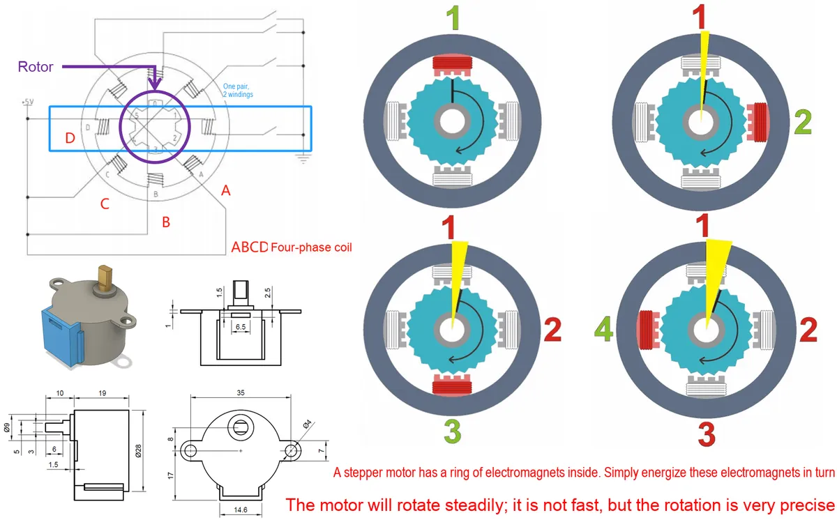
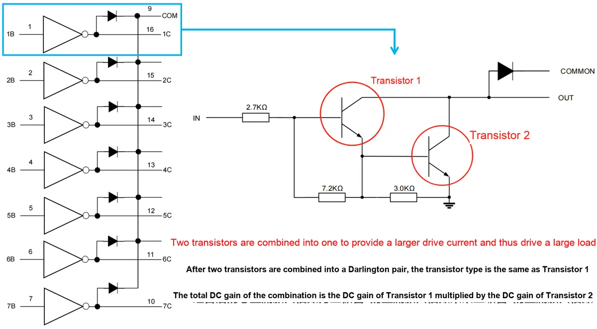
Here, when driving the 28BYJ-48 stepper motor, it is necessary to use a ULN2003 driver IC. The ULN2003 is a common 7-channel switch driver integrated circuit. We can use GPIO to drive the internal Darlington transistors (A Darlington transistor, also called a composite transistor, is formed by combining two triodes into one to provide a larger driving current for driving heavy loads) to control their on-off, so as to realize the control of high-current motor operation with low-current GPIO output. It is mainly used to drive different types of electronic loads, such as stepper motors, relays, LEDs and other small electromagnetic devices.
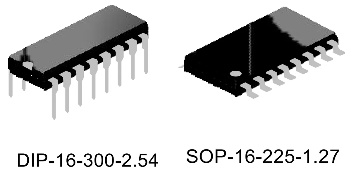
The ULN2003 is available in two packages: DIP-16 through-hole and SOP-16 surface-mount.
The main control methods for stepper motors are as follows: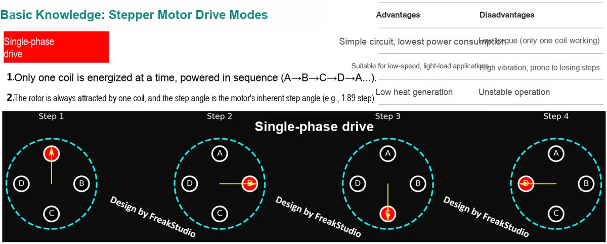
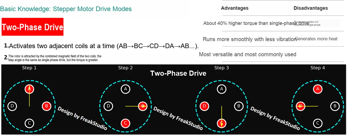
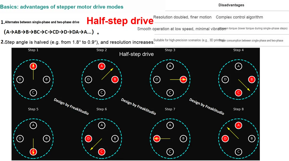
- Single-phase drive: It controls the motor to rotate by only one step angle at a time (only one phase winding is energized in each cycle), which is applicable to relatively simple motion control, yet features low precision and small torque.
- Bipolar drive: It controls the motor to rotate only half a step angle at a time (two phases of windings are energized simultaneously in each step), delivering relatively high torque yet requiring a slightly more complex structure and control scheme.
- Half-step drive: It controls the motor to rotate by half a step angle each time (by means of alternating power supply between single-phase and dual-phase) to achieve higher control accuracy.
3.4.2 Application Experiment
Here, we adopt the single-phase drive mode to drive the stepping motor. Simply put, the principle of the single-phase drive mode is as follows: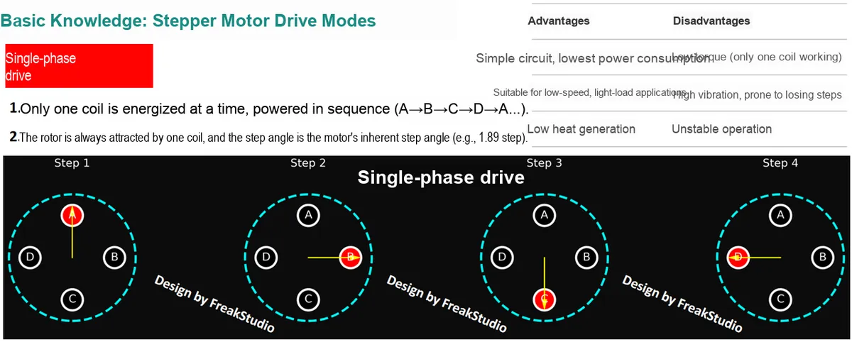
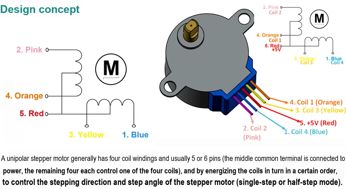
- 4-phase winding structure: The 28BYJ-48 stepper motor has 4 independent winding phases, which are controlled by the four pins IN1, IN2, IN3 and IN4 respectively.
- Sequential energization drive: By energizing these four phase windings in sequence, the stepper rotation of the rotor can be achieved. Each time the on-off state of one phase winding is switched, the rotor moves by one step angle.
- Hysteresis Structure: The rotor adopts a hysteresis structure, that is, the rotor is composed of a ring of permanent magnets, while the stator consists of 4 electromagnet windings. When a certain phase winding of the stator is energized, a magnetic pole will be generated, which attracts or repels the magnetic poles of the rotor, thus driving the rotor to rotate.
- Deceleration mechanism: The 28BYJ-48 has a built-in deceleration mechanism, which reduces the step angle from the motor's inherent 7.5° to 0.0625°, thus greatly improving the angular resolution.
Here, we use the long pin headers on the Fengya No. 1 Board - Universal Compatible Expansion Board to connect to the logic input interfaces on the Fengya No. 1 Board - Stepper Motor Driver Board, and the pins used are shown in the following table:
microcontroller pin | Motor drive pin | Stepper motor pins |
GPIO2 | IN1 | A |
GPIO3 | IN2 | B |
GPIO4 | IN3 | C |
GPIO5 | IN4 | D |
GND | GND | NC |
VBUS | VCC | COMMON |
Then connect the interface of the logic output section on the stepper motor driver board to the stepper motor:
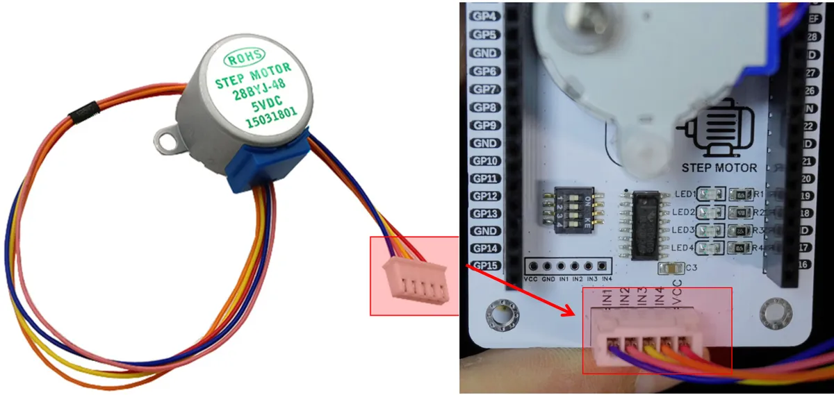
Meanwhile, toggle on the DIP switches on the Fengya No. 1 Board - Stepper Motor Driver Board:
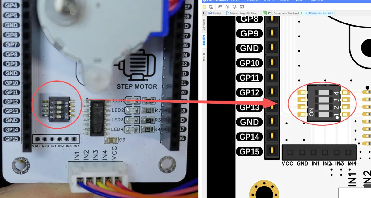
The overall connection is shown in the following figure:
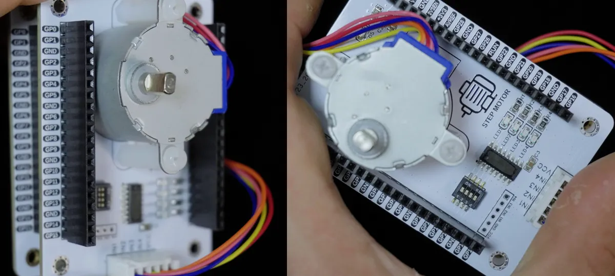
The sample code is as follows, which can be found in the folder of the supporting materials: elegance-devkit v1\Demo\04 GPIO_StepMotor
# Python env   : MicroPython v1.23.0
# -*- coding: utf-8 -*-
# @Time        : 2024/7/27 10:23 AM
# @Author      : Li Qingshui
# @File        : main.py
# @Description : GPIO class experiment: control a stepper motor via GPIO

# ======================================== Import Modules ========================================

# Hardware-related modules
from machine import Pin
# Time module
import time

# ======================================== Global Variables ============================================

# Initialize the GPIO pin tuple; each element is a Pin object
pins: tuple[Pin, ...] = (
    Pin(2, Pin.OUT),
    Pin(3, Pin.OUT),
    Pin(4, Pin.OUT),
    Pin(5, Pin.OUT)
)

# ======================================== Functions ============================================

def control_step_motor(step: int) -> None:
    """
    Controls the stepping logic of the stepper motor.

    According to the current step index, the corresponding pin is driven high and the other pins are driven low,
    implementing sequential control of the stepper motor.

    Args:
        step (int): Current step index, in the range 0 ~ 3.

    Returns:
        None
    """
    for index, pin in enumerate(pins):
        # The pin whose index equals the current step value is driven high; the other pins are driven low
        pin.value(index == step)

# ======================================== Initialization ==========================================

# Power-on delay of 3 s
time.sleep(3)
# Print debug message
print("FreakStudio: Using GPIO to control step motor")

# ======================================== Main Program =============================================

while True:
    # Iterate over the 4 step values 0 ~ 3
    for step in range(4):
        # Call the step control function
        control_step_motor(step)
        # Delay 4 ms for each step
        time.sleep_ms(4)
Burn the code, and you will see the stepper motor rotate while the indicator lights on the stepper motor driver module light up in sequence.
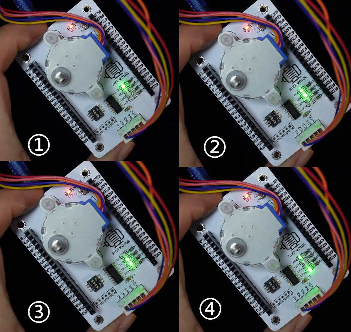
February 14.mp4 8.6 MB
Here, you can refer to the following link for the knowledge points related to the Python tuple data structure:
For a detailed explanation of the driving principle of unipolar stepper motors, please refer to the following video:
3.5 Rotary Encoder Experiment
3.5.1 Basic Knowledge of Rotary Encoder
Here, we use the EC11 rotary encoder component with 20 pulses and 20 positioning points, and its structure is as follows:
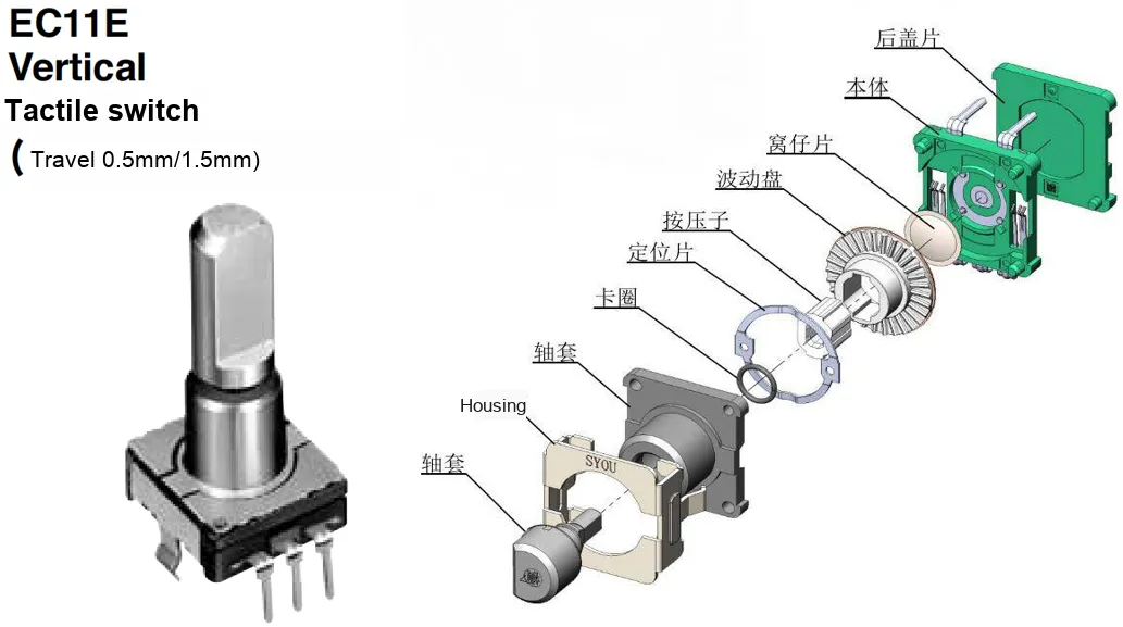
The names and functions of the respective components are as follows:
- Code wheel: A core component of an encoder that generates signals through rotational operation. It is equipped with equally spaced conductive strips on its surface; when the wheel rotates, these conductive strips sequentially come into contact with the output contacts, thereby generating pulse signals.
- Detent piece: It locates each rotational position and provides mechanical feedback, giving the encoder a distinct rotational feel. The EC11 we use features 20 detents, meaning there is a pause for every 18-degree rotation;
- Contact: works in coordination with the wave plate to detect the position change of the conductive strip and generate a signal;
- Shaft sleeve and housing: They provide physical structural support for the encoder, and electronic components and pins are usually mounted on the housing.
EC11 typically has 5 pins, as shown in the following figure: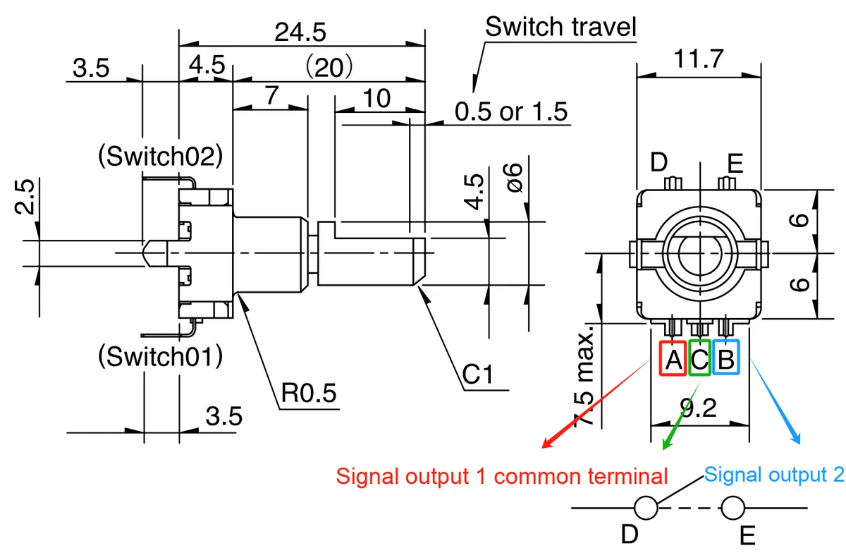
- Pin A (Red) Signal Output 1: Outputs rotation pulse signals
- Pin B (blue) Signal Output 2: Also outputs a pulse signal, but with a phase difference relative to Pin A
- Pin C (Green) Common Terminal: Common ground terminal for signal channels A and B
- Pins D and E: The two terminals of the push switch, which are short-circuited when the button is pressed.
Its working principle is as follows: the EC11 outputs incremental rotation signals through two signal channels (pins A and B). During rotation, the A and B signal channels generate interleaved pulses, and the rotation direction (clockwise or counterclockwise) can be determined by comparing the phase relationship between the two:
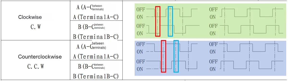
Simply put, it means:
- When rotating clockwise, phase A leads phase B by 90 degrees, that is, when phase A is at the falling edge, phase B is at low level; when phase A is at the rising edge, phase B is at high level.
- When rotating counterclockwise, phase B leads phase A by 90 degrees, that is, when phase A is at the falling edge, phase B is at a high level; when phase A is at the rising edge, phase B is at a low level.
It is not difficult to find that whenever a level transition occurs in Phase A or Phase B, the rotation direction can be determined simply by detecting the state of the other phase:
- Clockwise: both phases are either rising edges at the same time or falling edges at the same time;
- Counterclockwise: the two phases do not present rising edges simultaneously or falling edges simultaneously;
Meanwhile, the number of rotation steps (increment) can be determined in combination with pulse counting.
Here, the EC11 rotary encoder also comes with a push switch (pins D and E): when the encoder is pressed, its internal mechanical structure triggers a key signal, which is typically used for control or operation confirmation.
3.5.2 Application Experiment
In the following code, we have customized an EC11Encoder class, which reads the rotation steps and button status of the rotary encoder through interrupt processing, and updates the Progress Bar on the terminal in the main program loop to display the rotation degree of the rotary encoder.
Here, we need to insert the Fengya No. 1 Board - Universal Compatible Expansion Board into the Fengya No. 1 Board - LCD Screen Human-Machine Interaction Board, and turn on the RE-CLK, RE-DT and RE-SW on the DIP switch SWITCH2. The physical connection diagram is shown below:
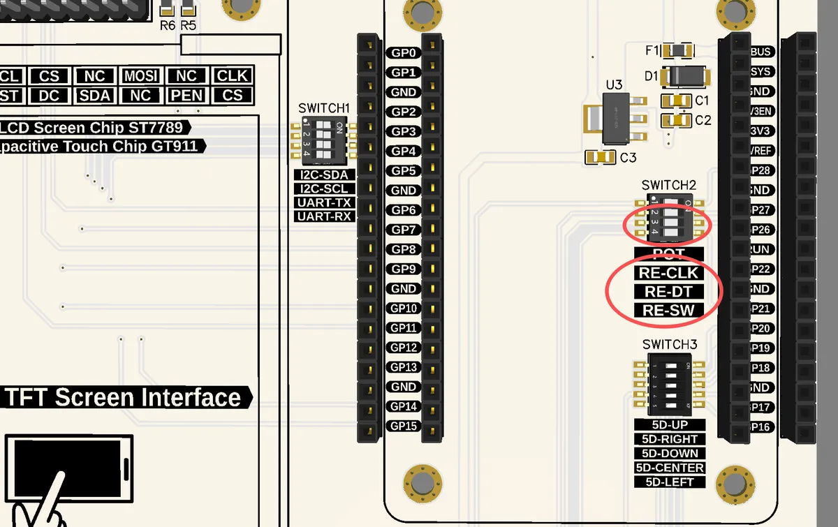
The wiring of the components is as follows:
EC11 Pin Functions | Raspberry Pi Pico pins | Description |
VCC (+3.3V) |
| Power supply voltage, connect to the 3.3V power output of the Pico |
GND |
| common ground wire |
Phase A |
| Encoder rotation signal A, for phase detection |
Phase B |
| Encoder rotation signal B, for phase detection |
Pushbutton SW |
| Encoder pushbutton switch, outputs low level when pressed |
The sample code is as follows, located in the folder of the supporting materials: elegance-devkit v1\Demo\05 GPIO_RotaryEncoder:
# Python env   : MicroPython v1.23.0
# -*- coding: utf-8 -*-
# @Time    : 2024/9/18 10:44 PM
# @Author  : Li Qingshui
# @File    : main.py
# @Description : GPIO class experiment: read the value of a rotary encoder

# ======================================== Import Modules =========================================

# Import hardware-related modules
from machine import Pin
# Import time-related modules
import time

# ======================================== Global Variables ============================================

# ======================================== Functions ============================================

# ======================================== Custom Classes ============================================

class EC11Encoder:
    """
    EC11 rotary encoder class, used to read the rotary encoder signals through GPIO pins, detect the rotation direction and count, and respond to button events.

    This class uses GPIO pins to read the A-phase and B-phase signals of the rotary encoder, and determines the rotation direction based on the rising edge of the A-phase signal and the state of the B-phase signal.
    It also monitors button press and release events on the button pin, which are used to reset the rotation count. Each button press clears the counter,
    so that the device can be reset with the button.

    Attributes:
        pin_a (Pin): GPIO pin object for the A-phase signal. Used to read the rotary encoder signal.
        pin_b (Pin): GPIO pin object for the B-phase signal. Used together with the A-phase signal to determine the rotation direction.
        pin_btn (Pin): GPIO pin object for the button signal. Used to detect button press and release.

        rotation_count (int): Rotation counter that records the number of rotation steps of the rotary encoder. A positive value means clockwise rotation, and a negative value means counterclockwise rotation.
        last_state_a (int): The A-phase signal state read last time. Used to determine the rotation direction.
        button_pressed (bool): Whether the button is pressed. True if the button is pressed, otherwise False.

    Methods:
        get_rotation_count(): Get the current rotation count.
        reset_rotation_count(): Reset the rotation counter.
        is_button_pressed(): Check whether the button is pressed.
        _handle_rotation(pin: Pin): Internal interrupt handler that processes the rotation signal and updates the rotation count.
        _handle_button(pin: Pin): Internal interrupt handler that detects button press and release events.
    """

    def __init__(self, pin_a: int, pin_b: int, pin_btn: int) -> None:
        """
        Initialize the EC11 rotary encoder.

        Args:
            pin_a (int): GPIO pin number for the A-phase signal.
            pin_b (int): GPIO pin number for the B-phase signal.
            pin_btn (int): GPIO pin number for the button signal.
        """
        self.pin_a = Pin(pin_a, Pin.IN)
        self.pin_b = Pin(pin_b, Pin.IN)
        self.pin_btn = Pin(pin_btn, Pin.IN, Pin.PULL_UP)

        # Rotation counter
        self.rotation_count = 0
        # Previous state of phase A
        self.last_state_a = self.pin_a.value()
        # Whether the button is pressed
        self.button_pressed = False

        # Set up interrupt handling
        self.pin_a.irq(trigger=Pin.IRQ_RISING, handler=self._handle_rotation)
        self.pin_btn.irq(trigger=Pin.IRQ_FALLING | Pin.IRQ_RISING, handler=self._handle_button)

    def _handle_rotation(self, pin: Pin) -> None:
        """
        Interrupt callback that detects the rotation direction of the rotary encoder.

        Triggered on the rising edge of phase A, and reads the state of phase B to determine the rotation direction.

        Args:
            pin (Pin): The phase A signal pin that triggered the interrupt.
        """
        current_state_b = self.pin_b.value()

        # Clockwise rotation
        if current_state_b == 0:
            self.rotation_count += 1
        # Counterclockwise rotation
        else:
            self.rotation_count -= 1

    def _handle_button(self, pin: Pin) -> None:
        """
        Interrupt callback that detects button press and release.

        Updates the state when the button is pressed, and resets the rotation counter when it is released.

        Args:
            pin (Pin): The button signal pin that triggered the interrupt.
        """
        # Button pressed
        if self.pin_btn.value() == 0:
            self.button_pressed = True
        # Button released
        else:
            self.button_pressed = False
        # Reset the rotation counter
        self.rotation_count = 0

    def get_rotation_count(self) -> int:
        """
        Get the current rotation count.

        Returns the rotation count; a positive value means clockwise, a negative value means counterclockwise.

        Returns:
            int: The current rotation count.
        """
        return self.rotation_count

    def reset_rotation_count(self) -> None:
        """
        Reset the rotation counter.

        Sets the rotation counter to zero.
        """
        self.rotation_count = 0

    def is_button_pressed(self) -> bool:
        """
        Detect whether the button is pressed.

        Returns the button state: True if the button is pressed, False if not.

        Returns:
            bool: Whether the button is pressed.
        """
        return self.button_pressed

# Terminal progress bar class
class ProgressBar:
    """
    Terminal progress bar class, used to display an updatable progress bar in the terminal.

    This class shows the progress of the current task by drawing a progress bar in the terminal. It supports dynamic updates of the progress bar and allows the user to
    customize the maximum value and the length of the bar. The bar uses green for the completed part and red for the remaining part.

    Attributes:
        max_value (int): Maximum value of the progress bar, representing the total progress of the task. When the current progress reaches this value, the bar shows 100%.
        bar_length (int): Total length of the progress bar, used to control its width. Defaults to 50.

    Methods:
        update(current_value: int) -> None: Updates the progress bar display; takes the current progress value.
        reset() -> None: Resets the progress bar to 0%, showing an all-red bar.
    """

    def __init__(self, max_value: int, bar_length: int = 50) -> None:
        """
        Initialize the progress bar.

        Args:
            max_value (int): Maximum value of the progress bar. The bar shows 100% when this value is reached.
            bar_length (int): Total length of the progress bar. Defaults to 50.
        """
        self.max_value = max_value
        self.bar_length = bar_length

    def update(self, current_value: int) -> None:
        """
        Update the progress bar.

        Calculates and updates the progress bar display based on the current value, ensuring the current value does not exceed the maximum value.

        Args:
            current_value (int): Current value of the progress bar.
        """
        if current_value > self.max_value:
            current_value = self.max_value
        if current_value < 0:
            current_value = 0

        progress = current_value / self.max_value
        block = int(self.bar_length * progress)

        # Green indicates progress, red indicates the remainder
        bar = '\033[92m' + '█' * block + '\033[91m' + '-' * (self.bar_length - block) + '\033[0m'
        print(f"\r[{bar}]", end='')

    def reset(self) -> None:
        """
        Reset the progress bar.

        Resets the progress bar to 0%, i.e. all red.
        """
        print(f"\r\033[91m[{'-' * self.bar_length}]\033[0m", end='')

# ======================================== Initialization ==========================================

# Power-on delay of 3 s
time.sleep(3)
# Print debug information
print("FreakStudio : GPIO read Rotary Encoder value")

# Create the EC11 rotary encoder object, using GPIO26 and GPIO27 as phase A and phase B, and GPIO21 as the button
encoder = EC11Encoder(pin_a=26, pin_b=27, pin_btn=21)
# Create the terminal progress bar object to display progress; 20 rotations reach 100%
progress_bar = ProgressBar(max_value=20)

# ========================================  Main Program  ===========================================

# Get the rotation count and button state in the main loop
while True:
    # Get the rotation count
    current_rotation = encoder.get_rotation_count()
    # print(f"Rotation count: {current_rotation}")
    # Update the progress bar
    progress_bar.update(current_rotation)
    # When the button is pressed, reset the progress bar
    if encoder.is_button_pressed():
        progress_bar.reset()
    # Update every 10ms
    time.sleep_ms(10)
Here, the core part that detects the rotation count and rotation direction of the rotary encoder is the _handle_rotation method; we configure the pin connected to phase A of the rotary encoder to input mode with rising-edge triggered interrupt, and set its interrupt callback function to the _handle_rotation method:
def _handle_rotation(self, pin: Pin) -> None:
    """
    Interrupt callback that detects the rotation direction of the rotary encoder.

    Triggered on the rising edge of phase A, and reads the state of phase B to determine the rotation direction.

    Args:
        pin (Pin): The phase A signal pin that triggered the interrupt.
    """
    current_state_b = self.pin_b.value()

    # Clockwise rotation
    if current_state_b == 0:
        self.rotation_count += 1
    # Counterclockwise rotation
    else:
        self.rotation_count -= 1
When the rising edge of the phase A signal is detected, the system enters the _handle_rotation method to acquire the state of the phase B signal and make a judgment:
- When the B-phase signal is at a low level, it is determined to be clockwise rotation, so the rotation counter
self.rotation_countincrements by 1 - When the B-phase signal is at a high level, it is judged as counterclockwise rotation, so the rotation counter
self.rotation_countis decremented by 1
At the same time, we also set the button of the rotary encoder to be triggered on the falling edge, and call the _handle_button method when the button is pressed, in which the button state is updated and the rotation counter is reset.
We use a custom ProgressBar class to dynamically display progress in the terminal. We can dynamically update the display of the Progress Bar via the update method, or call the reset method to reset the Progress Bar to zero for easy restarting of the display. The core code snippet is as follows:
def update(self, current_value: int) -> None:
    """
    Update the progress bar.

    Calculates and updates the progress bar display based on the current value, ensuring the current value does not exceed the maximum value.

    Args:
        current_value (int): Current value of the progress bar.
    """
    if current_value > self.max_value:
        current_value = self.max_value
    if current_value < 0:
        current_value = 0

    progress = current_value / self.max_value
    block = int(self.bar_length * progress)

    # Green indicates progress, red indicates the remainder
    bar = '\033[92m' + '█' * block + '\033[91m' + '-' * (self.bar_length - block) + '\033[0m'
    print(f"\r[{bar}]", end='')
In this code, we ensure that current_value stays within the valid range, i. e., no greater than the maximum value and no less than 0; then we calculate the proportion of the current value to the maximum value to obtain the number of blocks displayed in the Progress Bar.
In the code for building the Progress Bar section:
bar = '\033[92m' + '█' * block + '\033[91m' + '-' * (self.bar_length - block) + '\033[0m'The meaning of each part is as follows:
'\033[92m': ANSI escape code, sets the text color to green'█' * block: Green progress segment'\033[91m': ANSI escape code, sets the text color to red'-' *(self.bar_length - block): Remaining red portion'\033[0m': ANSI escape code, resets the text color to the default value
Next, we use the Print method to print the Progress Bar, and here we use the carriage return character '\r' to return to the start of the line so as to overwrite the previous Progress Bar output in the terminal; then we add the end parameter with a value of end='' to avoid line breaks after each print, so that the Progress Bar only prints dynamically updated content on the same line.
In the main program section, we continuously read the value of the rotary encoder and update the Progress Bar, and reset the Progress Bar when a key press is detected.
Burn the code, open the terminal, and the following content will be displayed:

3.5 Application Experiment.mp4 19.0 MB
When we rotate the EC11 encoder clockwise, we can see that the green rectangular box of the Progress Bar increases:

When we rotate the EC11 encoder counterclockwise, you can see that the green rectangular box of the Progress Bar decreases:

Here, we may find that when the rotary encoder rotates, the terminal Progress Bar sometimes jumps by several units. The reason is that the count value of the rotary encoder does not only change by one unit each time the rotary encoder rotates. We add the following code in the main loop to print the rotation count value of the rotary encoder:
print(f"Rotation count: {current_rotation}")Burn the code, run it, and then open the terminal:
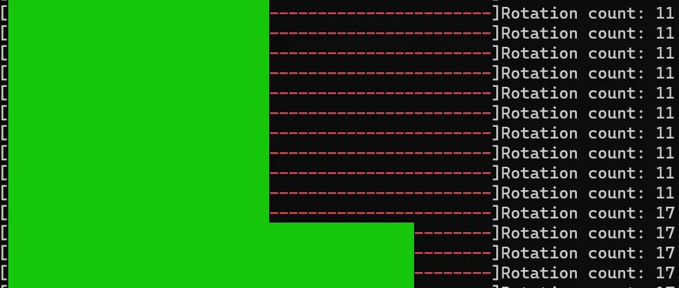
It can be observed that the count value of the rotary encoder sometimes jumps by several units when it rotates once. This is mainly because, as a mechanical device, when the user rotates the encoder, its contact points will repeatedly make and break contact in a short period of time, causing signal jitter and thus generating redundant count pulses.
To solve this problem, we can use a capacitor or an RC circuit to filter the signal, slow down its rapid changes and smooth out jitter; alternatively, in terms of software, we can judge the signals collected multiple times in a short period of time, and only regard the signal as valid when the same signal is detected for several consecutive times to address this issue.
In the timer chapter, we will use a timer to scan the encoder status every 10ms for debouncing.
Here, you can refer to the following articles for knowledge related to Object Oriented programming and custom classes in Python:
3.6 Five-way Button Experiment
3.6.1 Basic Knowledge of 5-Way Key
A five-way key is a common input device, typically used in the control interfaces of electronic products such as remote controls, game controllers and mobile devices. It contains five contacts inside: one common contact at the center, with multiple fixed contacts distributed around it. Its operating principle relies on the connection between the movable contact reed, the common contact and the surrounding fixed contacts to enable switching between multiple states. When the operating lever is moved, the movable contact reed comes into contact with the corresponding contact, thereby establishing an electrical circuit connection.
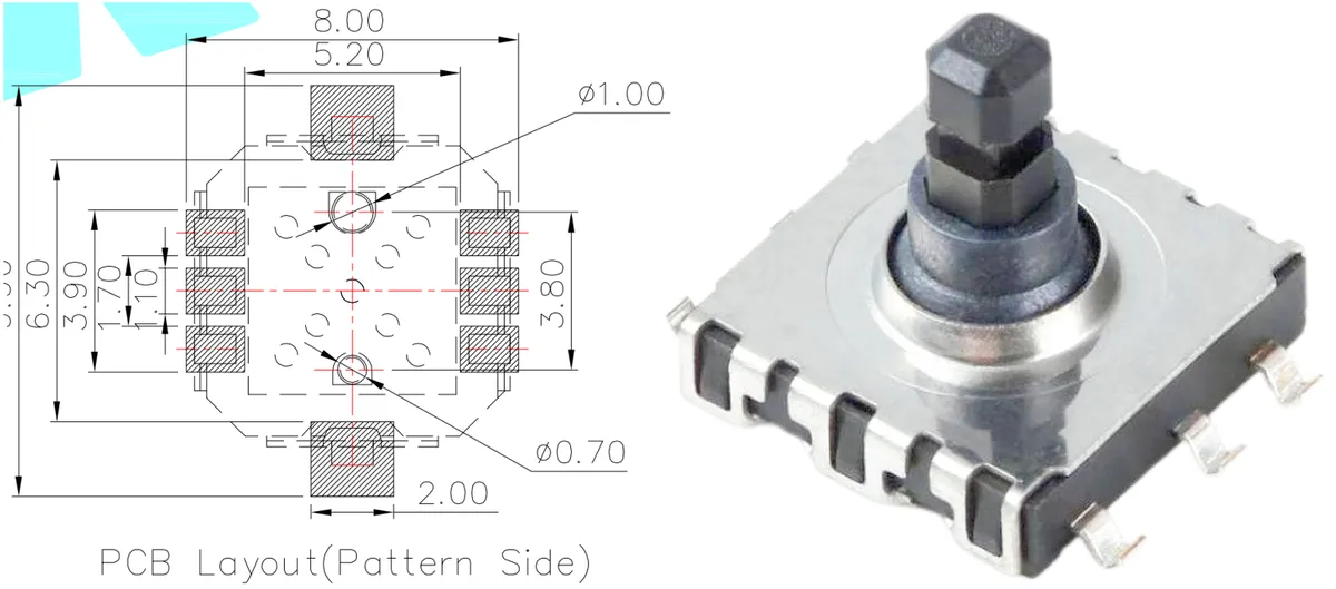
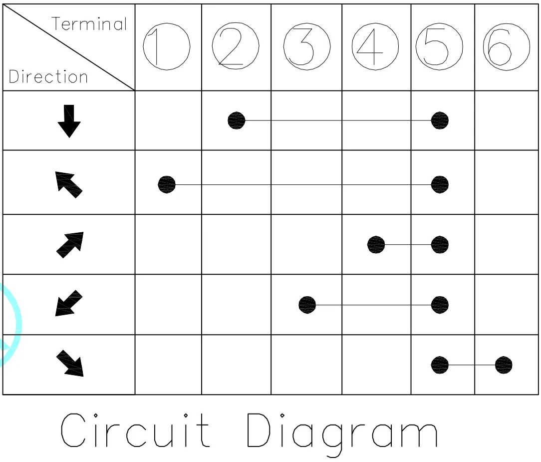
A 5-way key looks like a single button, but it actually integrates five distinct key states, allowing users to switch between multiple functions by pressing it in different directions. Here, we connect the common contact (COM terminal) of the 5-way key to the + 5V power supply. When none of the keys is pressed, the voltage measured at any of the keys is 0V, since all contacts are in an open-circuit state and no current flows; when any key is pressed, the movable contact reed of that key will connect with the common contact to form a closed circuit, and the voltage measured at the corresponding key will then rise to the supply voltage (5V).
3.6.2 Application Experiment
In the following program, we will use the GPIO pins of the Raspberry Pi Pico to read and process the input status of a 5-way joystick (with 7 buttons), and print the corresponding button information when a button is pressed. Here, we need to insert the Fengya No. 1 Board - Universal Compatible Expansion Board into the Fengya No. 1 Board - LCD Screen Human-Machine Interaction Board, and turn on all the options on the SWITCH3 DIP switch. The physical connection diagram is shown below:
The connection status of the 5-way button is shown in the following table, in which the common terminal (COM terminal) of the 5-way button is connected to the + 3V3 power supply:
5-way button pins | Raspberry Pi Pico pins | Description |
COM (Common Terminal) |
| Common power terminal, connect to the 3.3V power output of the Pico |
UP |
| Up direction key input |
DOWN |
| Down arrow key input |
LEFT |
| Left direction key input |
RIGHT |
| Right direction key input |
MID (Confirm Key) |
| Center button input |
Sample code is as follows, located in the folder of the supporting materials: elegance-devkit v1\Demo\06 GPIO_5DJoystick:
# Python env   : MicroPython v1.23.0
# -*- coding: utf-8 -*-
# @Time    : 2025/1/2 2:10 PM
# @Author  : Li Qingshui
# @File    : main.py
# @Description : GPIO experiment, 5D joystick experiment

# ======================================== Import Modules =========================================

# Import hardware-related modules
from machine import Pin
# Import time-related modules
import time

# ======================================== Global Variables ============================================

# ======================================== Functions ============================================

# ======================================== Custom Classes ============================================

# Custom five-way button class
class DirectionalButton:
    """
    A class for handling the five-way button.

    This class encapsulates the functionality of the five-way button, including detection of the UP, DOWN, LEFT, RIGHT, MID, SET and RST buttons.
    Each button listens for press and release events through its configured GPIO pin. The button states are stored in the `button_state` dictionary.
    When a button state changes, an internal interrupt handler is triggered to update the state. The methods provided include getting the state of a specific button, resetting all button states, and so on.

    Attributes:
        up_pin (Pin): GPIO pin object for the UP button. It is set to input mode with the pull-down resistor enabled during initialization.
        down_pin (Pin): GPIO pin object for the DOWN button. It is set to input mode with the pull-down resistor enabled during initialization.
        left_pin (Pin): GPIO pin object for the LEFT button. It is set to input mode with the pull-down resistor enabled during initialization.
        right_pin (Pin): GPIO pin object for the RIGHT button. It is set to input mode with the pull-down resistor enabled during initialization.
        mid_pin (Pin): GPIO pin object for the MID button. It is set to input mode with the pull-down resistor enabled during initialization.
        set_pin (Pin): GPIO pin object for the SET button. It is set to input mode with the pull-down resistor enabled during initialization.
        rst_pin (Pin): GPIO pin object for the RST button. It is set to input mode with the pull-down resistor enabled during initialization.
        button_state (dict): Button state dictionary that records the current state of each button. The keys are button names and the values are button states (True for pressed, False for not pressed).

    Methods:
        get_button_state(button): Gets the current state of the specified button. Returns True if pressed, False if not pressed.
        reset_all(): Resets the state of all buttons, setting all button flags to False (not pressed).
        _handle_button(pin): Button interrupt handler that sets the button state according to the button's pin.
    """

    def __init__(self, up_pin: int, down_pin: int, left_pin: int, right_pin: int,
                 mid_pin: int, set_pin: int = None, rst_pin: int = None) -> None:
        """
        Initialize the five-way button class, configuring the GPIO pins of all buttons and enabling the built-in pull-up resistors.

        Args:
            up_pin (int): GPIO pin for the UP button.
            down_pin (int): GPIO pin for the DOWN button.
            left_pin (int): GPIO pin for the LEFT button.
            right_pin (int): GPIO pin for the RIGHT button.
            mid_pin (int): GPIO pin for the MID button.
            set_pin (int): GPIO pin for the SET button.
            rst_pin (int): GPIO pin for the RST button.

        Returns:
            None
        """
        # Initialize the button pins for each direction, set them to input mode, and enable the pull-down resistors
        self.up_pin     = Pin(up_pin, Pin.IN, Pin.PULL_DOWN)
        self.down_pin   = Pin(down_pin, Pin.IN, Pin.PULL_DOWN)
        self.left_pin   = Pin(left_pin, Pin.IN, Pin.PULL_DOWN)
        self.right_pin  = Pin(right_pin, Pin.IN, Pin.PULL_DOWN)
        self.mid_pin    = Pin(mid_pin, Pin.IN, Pin.PULL_DOWN)

        if set_pin is not None and rst_pin is not None:
            self.set_pin    = Pin(set_pin, Pin.IN, Pin.PULL_DOWN)
            self.rst_pin    = Pin(rst_pin, Pin.IN, Pin.PULL_DOWN)

        # Initialize the button state dictionary, with a default value of False (not pressed)
        self.button_state = {
            'UP': False,
            'DOWN': False,
            'LEFT': False,
            'RIGHT': False,
            'MID': False,
            'SET': False,
            'RST': False
        }

        # Set the interrupt handler for each button pin
        self.up_pin.irq(trigger=Pin.IRQ_FALLING | Pin.IRQ_RISING, handler=self._handle_button)
        self.down_pin.irq(trigger=Pin.IRQ_FALLING | Pin.IRQ_RISING, handler=self._handle_button)
        self.left_pin.irq(trigger=Pin.IRQ_FALLING | Pin.IRQ_RISING, handler=self._handle_button)
        self.right_pin.irq(trigger=Pin.IRQ_FALLING | Pin.IRQ_RISING, handler=self._handle_button)
        self.mid_pin.irq(trigger=Pin.IRQ_FALLING | Pin.IRQ_RISING, handler=self._handle_button)

        if set_pin is not None and rst_pin is not None:
            self.set_pin.irq(trigger=Pin.IRQ_FALLING | Pin.IRQ_RISING, handler=self._handle_button)
            self.rst_pin.irq(trigger=Pin.IRQ_FALLING | Pin.IRQ_RISING, handler=self._handle_button)

    def _handle_button(self, pin: Pin) -> None:
        """
        Button interrupt handler that sets the button state according to the button's pin.

        Updates the state of the corresponding button each time a button is pressed or released.

        Args:
            pin (Pin): The button pin that triggered the interrupt.

        Returns:
            None
        """
        if pin == self.up_pin:
            self.button_state['UP'] = (pin.value() == 1)
        elif pin == self.down_pin:
            self.button_state['DOWN'] = (pin.value() == 1)
        elif pin == self.left_pin:
            self.button_state['LEFT'] = (pin.value() == 1)
        elif pin == self.right_pin:
            self.button_state['RIGHT'] = (pin.value() == 1)
        elif pin == self.mid_pin:
            self.button_state['MID'] = (pin.value() == 1)
        elif pin == self.set_pin:
            self.button_state['SET'] = (pin.value() == 1)
        elif pin == self.rst_pin:
            self.button_state['RST'] = (pin.value() == 1)

    def get_button_state(self, button: str) -> bool:
        """
        Get the current state of the specified button.

        Checks whether the specified button is pressed.

        Args:
            button (str): The button to query. Supports 'UP', 'DOWN', 'LEFT', 'RIGHT', 'MID', 'SET', 'RST'.

        Returns:
            bool: Returns the state of the specified button. True means pressed, False means not pressed.
        """
        return self.button_state.get(button, False)

    def reset_all(self) -> None:
        """
        Reset the state of all buttons to not pressed.

        Used when the state of all buttons needs to be cleared in certain scenarios.

        Args:
            None

        Returns:
            None
        """
        for button in self.button_state:
            self.button_state[button] = False

# ======================================== Initialization ==========================================

# Power-on delay of 3 s
time.sleep(3)
# Print debug information
print("FreakStudio : GPIO read 5D Joystick value")

# Create the five-way button object, using GPIO 16 to GPIO 20 to connect the buttons
button = DirectionalButton(up_pin=20, down_pin=18, left_pin=16, right_pin=19, mid_pin=17)

# ========================================  Main Program  ===========================================

# Main loop: read the button states and print them
while True:
    # Check whether any button is pressed
    for button_name in ['UP', 'DOWN', 'LEFT', 'RIGHT', 'MID', 'SET', 'RST']:
        # If a button is pressed, print the button name and state
        if button.get_button_state(button_name):
            print(f"{button_name} button is pressed.")

    # Loop every 100 milliseconds
    time.sleep(0.1)
DirectionalButton class encapsulates the detection and status management for the 7 buttons (UP, DOWN, LEFT, RIGHT, MID, SET, RST) of the 5-way joystick. Each button corresponds to a GPIO pin, and the button status is detected in real time via interrupt, with the following methods:
- Constructor
__init__: This constructor function accepts seven pin parameters, which are respectively connected to the 7 buttons (UP, DOWN, LEFT, RIGHT, MID, SET, RST) of the 5-way joystick. It usesPin.INto configure the pins as input mode, and enables the pull-down resistor viaPin.PULL_DOWN(since the state of the input pin is low level0when the button is not pressed, and becomes high level1when pressed). - Interrupt handling method
_handle_button: The interrupt function will be triggered each time a button is pressed (IRQ_FALLING) or released (IRQ_RISING). The button status is updated by checking the pin level: when pressed, the GPIO pin is at high level (1), and when released, it is at low level (0). Each button has a corresponding status dictionary (button_state) that stores whether the button is pressed. - Get key state
get_button_state: This function takes a key name (e. g.'UP') and returns the current state of the key, whereTrueindicates pressed,Falseindicates not pressed, and the state of the corresponding key is returned via the dictionary'sget ()method. - Reset all key states
reset_all: This function sets the state of all keys toFalse, which means resetting their state to "not pressed", and it resets the state of all keys by traversing the dictionary.
In the main loop, we create an instance of the DirectionalButton class, and pass the pin numbers to the corresponding button pins. Here, GPIO pins 16 to 22 of the Raspberry Pi Pico are used to connect the various buttons of the joystick, and in the main loop, the program continuously checks the state of each button;For each button, call the get_button_state () method to get its current state. If the button is pressed, print the relevant information (e. g., "UP button is pressed. "). After each loop iteration, use time.sleep (0.1) to add a 100-millisecond delay, so as to avoid reading the button state too frequently and reduce the CPU load.
Burn the program, open the terminal, and the following content will be displayed:
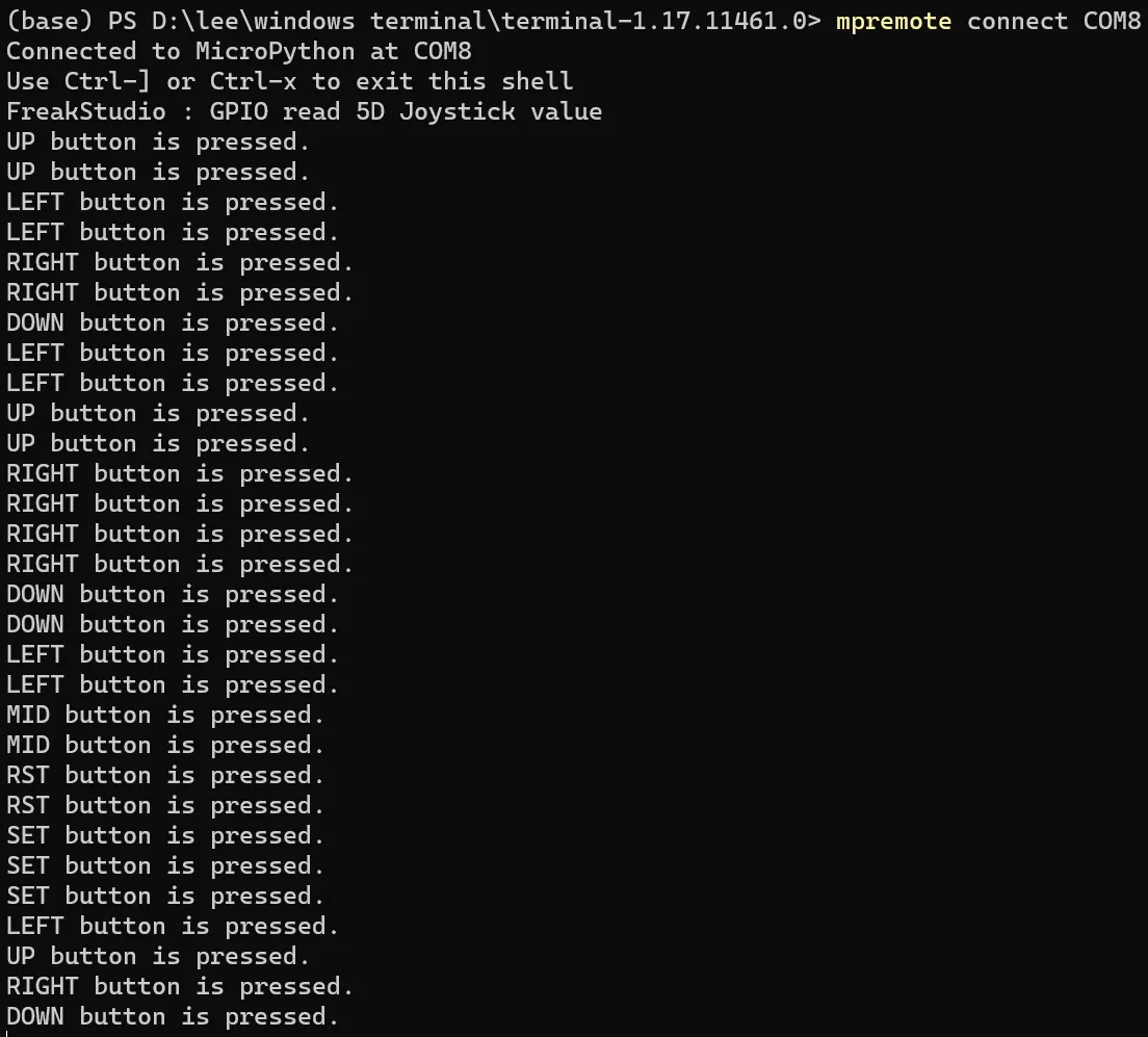
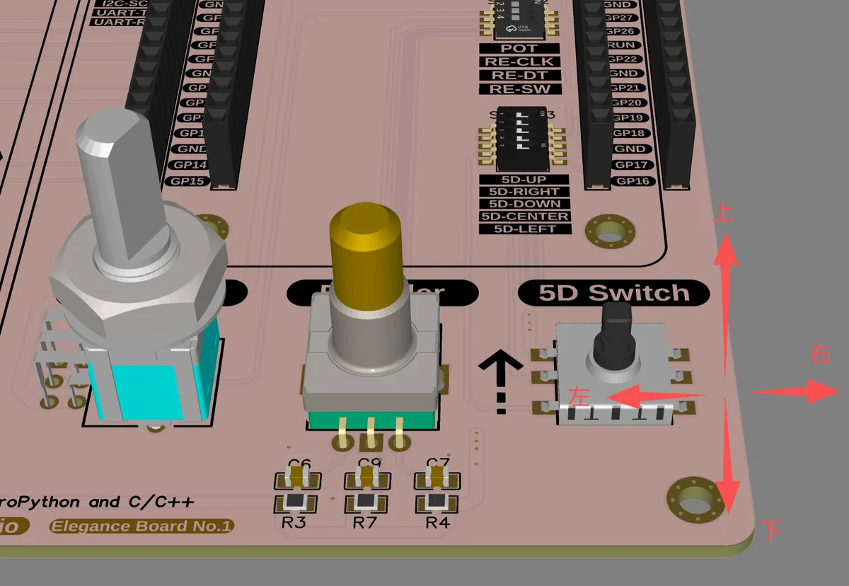
It can be seen that when different keys are pressed, the status information of the corresponding key can be displayed.
References
- Essentials of Microcontroller Use Learning about Peripherals: GPIO
https://www.renesas.com/us/en/support/engineer-school/mcu-programming-peripherals-01-gpio
- General-purpose input/output
https://en.wikipedia.org/wiki/General-purpose_input/output
- Access module registers in MicroPython via the mem function
https://blog.csdn.net/zhuoqingjoking97298/article/details/121704275
- The Pico In MicroPython: Direct To The Hardware
Programming the Raspberry Pi Pico/W In MicroPython Second Edition
https://www.i-programmer.info/programming/148-hardware/15076-the-pico-in-micropython-direct-to-the-hardware.html#google_vignette
- Elegant Implementation of Interrupts in MicroPython
https://www.skyone.host/2021/micropython-interrupt
- Write interrupt handlers
https://mpython.readthedocs.io/zh/master/reference/isr_rules.html
- Signal Class – Control and Detect External I/O Devices
http://www.86x.org/en/latet/library/machine.Signal.html
- Test the Signal function of MicroPython in MM32F3277
https://blog.csdn.net/zhuoqingjoking97298/article/details/121625627
- 28BYJ-48 Unipolar Stepper Motor
http://www.taichi-maker.com/homepage/reference-index/motor-reference-index
- EC11 rotary encoder
https://wiki.lckfb.com/zh-hans/dkx-stm32f103c8t6/module/sensor/ec11.html
Version Record
Version Number | Modifier | Time | Content |
v1.0.0 | Li Zisheng | 2025/09/16 | Document initialized, based on MicroPython version V1.23.0. |
v1.0.1 | Li Zisheng | 2025/09/16 | Edit some images. |
v1.1.0 | Li Zisheng | 2025/12/20 | Supplement basic knowledge to complete this document. |
v1.2.0 | Li Zisheng | 2026/02/14 | Improve the stepper motor section. |