
Contents
Young makers, today let’s unlock a "little steward that can safely drive motors" ⚙️!
Previously, when we used ordinary modules to drive motors, high currents might damage the development board. This optocoupler-isolated MOSFET single-motor drive module acts like a "security firewall" installed on the development board: it can not only drive the motor to run, but also protect the development board from being burned out by high currents — it’s extremely reliable ✨!
1. Module Introduction
Want to get your motor running but worried that a large current will burn out your development board? This module is your "safety solution"!
It is a isolated motor drive module whose core is the combination of "optocoupler + MOS tube":
- 🛡️ Optocoupler Isolation: Acting like a "signal translator", it transmits the weak signals from the development board to the MOSFET via optical means, completely isolating the development board from the high-current circuit of the motor to prevent the motor's electrical surge from damaging the development board;
- ⚙️ MOSFET Driver: It acts like a "power switch" — when the optocoupler's signal triggers the MOSFET, it allows high current to flow to the motor and drives it to rotate stably.
Compared with ordinary motor drive modules, it has the following features:
- 🛡️ Electrical Isolation: Thoroughly isolate the development board from the motor circuit to protect the development board from high-current surges;
- ⚡ Strong driving capability: It can drive components ranging from small toy motors to large-sized small DC motors;
- 🎮 Simple control: The "run/stop" and rotational speed of the motor can be controlled simply by high and low level signals or PWM signals;
- 🧩 Wide application scenarios: suitable for projects requiring motor drive such as small cars, robots, and toys.
In graphical programming, these blocks are commonly used:
PWM #6Block: Output PWM signal to control motor rotation (the larger the duty cycle, the faster the rotating speed);delayblock: controls the duration for which the motor rotates;- Sequential execution block: implements simple control of "start → delay → stop".
In practical projects, it is often used for the following purposes:
- Motor Drive of Intelligent Car (Enabling the Car to Move Forward and Backward)
- Robot joint actuation (controlling the rotation of arms and wheels)
- The power source of interactive toys (e. g. electric cars, carousels)
Popular Science: What is Optocoupler Isolation?
An optocoupler acts like a "bridge that transmits signals via light": the electrical signal from the development board is converted into light, which passes through an insulating layer, and then converted back into an electrical signal to be sent to the MOSFET. In this way, the circuits of the development board and the motor are completely isolated from each other, so the high current of the motor will not interfere with the development board, thoroughly eliminating the risk of burning it out.
2. Wiring Instructions
To get a motor running safely, the first step remains the same: connect the wires correctly!
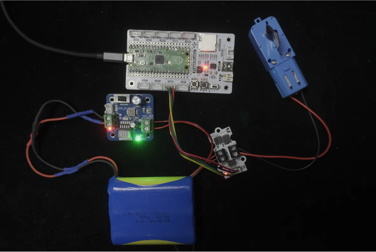
We connect the optocoupler-isolated MOSFET single-motor drive module to the digital interface DIO0 of the development board, and the corresponding relationship is as follows:
Development Board Pins | Module Pins | Description |
Pin 6 |
|
|
Pin 7 |
| - |
- |
| Power Supply |
- |
| Power Supply |
- |
| Motor |
📌 Note
- When the development board outputs a PWM signal with a high duty cycle, the optocoupler triggers the MOSFET to turn on, and the motor starts to rotate;
- When the output duty cycle is 0, the MOSFET turns off and the motor stops rotating.
3. Example: The motor stops after rotating for 5 seconds
Experimental Objective: Make the motor run at a stable speed for 5 seconds and then stop automatically, so as to intuitively experience the safety control effect of "optocoupler isolation + MOS drive".
Little Thoughts in Daily Life: When you press the forward button on a remote-controlled car, the motor spins to move the car forward, and it stops once you release the button — this follows a similar control logic. Now let's build our own "safe and controllable small motor"!
The graphical program is as follows:
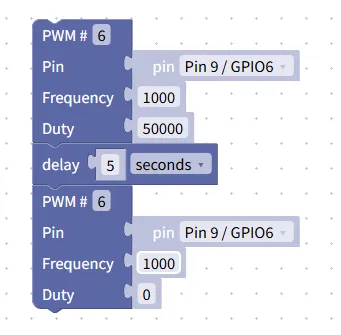
Building Block Assembly Steps:
- Starting Motor (PWM Output)
- Drag in
PWM #6block; - Selected Pin:
Pin 9 / GPIO6(corresponding to DIO0 interface); - Set the
Frequencyto1000(the frequency for stably driving the motor); - Set
Dutyto50000(medium duty cycle, corresponding to medium rotational speed);
- Drag in
- Set rotation duration
- Drag in the
delayblock and set it to5seconds → make the motor rotate continuously for 5 seconds;
- Drag in the
- Stop the motor (turn off PWM)
- Drag in another
PWM #6block; - Pin retention
Pin 9 / GPIO6; Frequencyremains1000;- Set
Dutyto0→ Turn off the output, and the motor stops rotating.
- Drag in another
Experimental Effect:
- After the program runs, the motor immediately starts rotating at a medium speed;
- The motor will stop rotating automatically after 5 seconds;
- The entire process requires no manual intervention, and the development board remains in a safely isolated state throughout.
Graphical blocks will be automatically converted into MicroPython code, and the running results will be displayed:
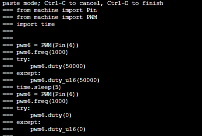
Directly importable building blocks:
Motor.xml 2 KB
Tips
- If the motor does not rotate:
- Check whether the pins are selected correctly (
Pin 9 / GPIO6) and whether the wiring is secure; - Verify that the 5V power supply is normal and check whether the motor is stuck by foreign objects;
- Try increasing the duty cycle (e. g., 60000) to raise the motor speed.
- Check whether the pins are selected correctly (
- What should I do if the motor speed is unstable?
- Ensure that
Frequencyis set to around 1000, which is a stable frequency for driving DC motors; - Check whether the motor is worn out or the supply voltage is stable.
- Ensure that
- Advanced Gameplay:
- Equipped with a sliding rheostat module, the PWM duty cycle is controlled via the rheostat value to realize "manual motor speed regulation";
- Equipped with a line-tracking module, the car will automatically stop the motor when it touches a black line, making it a "line-tracking car".
✨ Interactive Quick Question
- Think about it: Why can optocoupler isolation protect the development board? What are the risks if you directly use the pins of the development board to drive the motor without an optocoupler?
- Try this: Change
Dutyfrom 50000 to 65535 (the maximum duty cycle) and see whether the motor speed increases or decreases. Then change it to 30000 to experience different speed effects.
Summary
- The optocoupler-isolated MOSFET single-motor drive module is a safety-type motor drive module that achieves safety control through optocoupler isolation combined with MOSFET driving;
- It can completely isolate the development board from the motor circuit, preventing the development board from being damaged by high current, and meanwhile drive the motor to rotate stably.
- The basic usage is simple control following the sequence of "PWM start → delay → PWM stop", while the advanced usages include speed regulation and intelligent control;
- It is a core module for power projects such as small cars and robots, featuring high safety and reliability.