
Contents
Young makers, today let’s unlock a "magic matrix that emits invisible ultraviolet light" 🔮!
We cannot see ultraviolet light with our naked eyes in daily life, yet it can make fluorescent paper glow and sterilize small items. The MOSFET-based UV lamp matrix module acts just like a "canvas for invisible light"; it also supports PWM adjustment of ultraviolet intensity, making it incredibly cool for fluorescent graffiti or as a mini sterilization device ✨!
1. Module Introduction
Ultraviolet rays are invisible light, and the pins of ordinary development boards cannot directly drive UV lamps. The core of this module is a MOSFET driving circuit: UV lamps require a large current to turn on; the MOSFET acts as an "electronic switch" that can control a large current with the small signal (PWM) output from the development board. This not only protects the development board but also enables the UV lamp to emit light stably, and it also supports precise adjustment of ultraviolet intensity via PWM.
Compared with conventional direct-drive UV lamps, it features the following characteristics:
- 🔮 Invisible Light Output: Emits ultraviolet rays that are invisible to the human eye, suitable for fluorescence interaction and disinfection experiments;
- 🎛️ PWM Dimming: Capable of continuously adjusting the UV intensity from low to high to adapt to different scenarios;
- 🔌 Safety-driven design: MOSFET isolates high current to prevent the development board from being burned out;
- 🧩 Versatile gameplay: Suitable for projects such as fluorescent graffiti boards, mini sterilization boxes, and ultraviolet intensity demonstrators.
In graphical programming, these blocks are commonly used:
count withloop block: Generates continuously varying values to adjust UV intensity;PWM #6Building Block: Configure the pins, frequency and duty cycle (intensity) of the UV lamp;printblock: outputs the value of the current intensity;delayBlock: Controls the speed of intensity change;set output pinBlock: Finally turn off the UV lamp matrix.
In practical projects, it is often used for the following purposes:
- Fluorescent interactive installations (e. g., those that make fluorescent paper display hidden patterns)
- Mini Sterilizer (for disinfecting the surfaces of small items)
- Ultraviolet Intensity Demonstration (Observe the Effects of Different Intensities on Fluorescent Substances)
Popular Science: Why Use MOSFETs to Drive UV Lamps?
UV lamps require a higher current than the pins of a development board can supply when operating, and direct connection will burn out the development board. A MOSFET can use a small signal (such as PWM) output by the development board to control a large current, just like using a small key to open a large sluice gate — this is not only safe but also enables the UV lamp to work stably.
2. Wiring Instructions
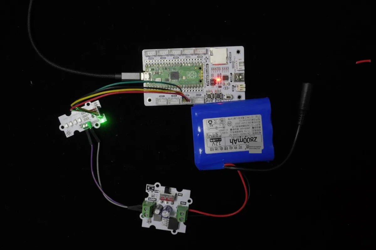
To make the UV lamp matrix emit "invisible light", it is necessary to separate the signal circuit from the power supply circuit for wiring:
2.1🔌 Signal Loop (Development Board ↔ Module)
This part transmits the control signals of the development board. We will connect the MOSFET-based UV ultraviolet lamp matrix module to the digital interface DIO0 of the development board, and the corresponding relationship is as follows:
Development Board Pins | Matrix light module pins | Description |
Pin 6 |
| The pin on the MCU that generates PWM waveform output or high/low level output |
Pin 7 |
| - |
2.2⚡ Power Supply Circuit (Power Supply ↔ Module)
This section supplies the operating current for the UV lamp matrix.
LM2596S Adjustable Power Supply Module | Matrix Light Module Pins | Description |
| Green terminal | Power Supply |
|
| Connect the battery |
📌 Note
- When the development board outputs a PWM signal, the MOS transistor adjusts the current of the UV lamp according to the duty cycle: the larger the duty cycle (the higher the value), the stronger the ultraviolet intensity;
- When the duty cycle is 0, the UV lamp turns off.
3. Example: Demonstration of UV Intensity Gradient
Objective of the Experiment:
Let the UV intensity of the UV lamp matrix start from 0, increase by one gear (step size: 3000) every 1 second until reaching 36000, then automatically turn off the matrix, and meanwhile print the current intensity value in the terminal to intuitively experience the effect of PWM dimming.
Little Life Insight: The ultraviolet disinfection lamps in hospitals can adjust their intensity, which follows a similar principle. Now let's make an "Ultraviolet Intensity Gradient Demonstrator"!
The graphical program is as follows:
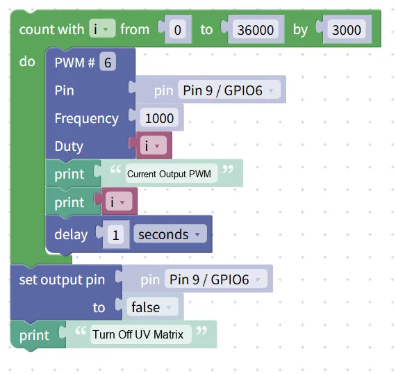
Building Block Assembly Steps:
- Generate intensity gradient values
- Drag in
count with i from 0 to 36000 by 3000blocks; - Let the variable
istart from 0 and increment by 3000 each time to simulate the change of ultraviolet intensity from 0 to the maximum.
- Drag in
- Configure PWM output
- Drag
PWM #6block into the loop; - Selected Pin:
Pin 9 / GPIO6(corresponding to DIO0 interface); - Set the
Frequencyto1000(the frequency for stably driving the UV lamp); - Set
Dutytoi(use variable i to control the duty cycle to achieve intensity variation).
- Drag
- Print strength value
- Add
print "Current output PWM"andprint iblocks to display the current intensity in the terminal.
- Add
- Control the rate of change
- Drag in the
delayblock and set it to1second → this makes the intensity change smoother and easier to observe.
- Drag in the
- Turn off the UV lamp matrix
- After the loop ends, drag in the
set output pinblock; - Selected Pin:
Pin 9 / GPIO6; - Set to
false→ turn off the output, and the UV lamp matrix stops emitting light; - Add the
print "Turn off the UV matrix"block to indicate the end of the experiment.
- After the loop ends, drag in the
Experimental Effect:
C2179.MP4 140.0 MB
- After the program runs, the ultraviolet intensity of the UV lamp matrix increases once every 1 second. You can hold a fluorescent paper close to it and observe that the fluorescent brightness gradually becomes brighter;
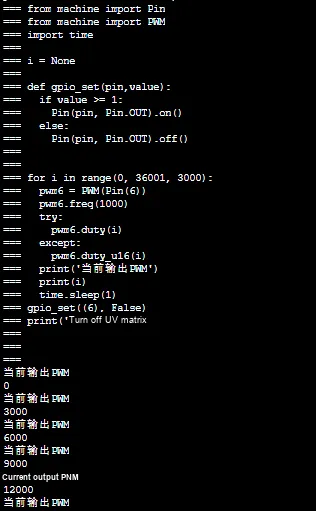
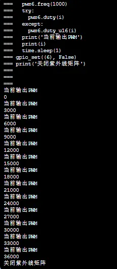
- The terminal will synchronously print the intensity value for each instance (0,3000,6000…36000);
- Finally, the matrix shuts down automatically, and the terminal prints "Ultraviolet matrix closed".
Graphical blocks will be automatically converted into MicroPython code, and the running results will be displayed:
Directly importable building blocks:
UV matrix.xml 4 KB
Tips
- 🔔 Safety Reminder:
- Ultraviolet rays are harmful to the eyes and skin. Do not look directly at the UV lamp during the experiment, and do not touch the glowing lamp beads with your bare hands.
- Be sure to turn off the UV lamp array after the experiment to avoid prolonged exposure to ultraviolet rays.
- If the UV lamp does not turn on:
- Check whether the signal pins are connected correctly (
Pin 9 / GPIO6) and whether the wiring is secure; - Confirm that the 5V power supply is normal, and check whether the GND of the module is connected to the GND of the development board.
- Check whether the signal pins are connected correctly (
- Advanced Gameplay:
- Draw a hidden pattern on paper with fluorescent paper, and turn on the UV light matrix to make the pattern visible;
- Paired with a light sensor, it automatically activates the UV lamp when ambient light dims, simulating an automatic disinfection scenario.
✨ Interactive Quick Question
- Just think: Why is ultraviolet light invisible? How do we know that a UV lamp is emitting light?
- Try this: Change the step size in
count withfrom 3000 to 6000, and see whether the intensity change will become faster or slower?
Summary
- The MOSFET-based UV lamp matrix module is a invisible light output module that drives UV lamps to emit ultraviolet rays via MOSFETs;
- It supports PWM dimming, which enables continuous intensity adjustment from dim to bright, making it suitable for applications such as fluorescence interaction and disinfection experiments.
- The basic application is to achieve intensity gradient through "loop + PWM", while the advanced application is to combine fluorescent materials to create interactive devices;
- Always pay attention to safety during the experiment and avoid direct exposure of ultraviolet rays to your eyes and skin.