
Contents
- 1. Module Introduction
- 2. Wiring Instructions
- 2.1 Signal Loop (Development Board ↔ Servo Driver Module)
- 2.2 Power Supply Circuit (Power Supply ↔ Servo Drive Module)
- 2.3 Servo Connection (Servo Driver Module ↔ Servo)
- 3. Install the PCA9685 library function
- 4. Example: Demonstration of Cooperative Rotation of Dual Servos
Young makers, today let's unlock a "super commander that can control 16 servo motors at the same time" 🤖!
Previously, controlling a single servo motor required occupying one pin on the development board. However, this 16-channel PWM servo driver module based on the PCA9685 chip only needs two I2C wires to drive 16 servo motors simultaneously, enabling the robot arms and car steering to move flexibly — it’s incredibly powerful ✨!
1. Module Introduction
Want to move multiple joints of your robot at the same time but worry that your development board doesn't have enough pins? This module is your ultimate tool for controlling multiple servo motors!
It is an I2C to multi-channel PWM output module with the PCA9685 16-channel PWM driver chip as its core: the development board only needs to send commands via the I2C interface (two wires: SDA and SCL), and the chip can output 16 independent PWM signals to precisely control the angle of each servo, perfectly solving the problem of insufficient pins on the development board.
Compared with direct driving via the pins of the development board, it has the following features:
- 🎮 16-channel independent control: capable of driving 16 servos simultaneously to meet the requirements of multi-joint projects such as robots and robotic arms;
- 🚀 High-efficiency I2C communication: Only 2 wires are required to control 16 channels of output without occupying a large number of pins on the development board;
- 🎯 Precise PWM: The output frequency and pulse width are adjustable, enabling the steering gear to rotate more smoothly with more accurate angles;
- 🔌 Flexible power supply: It supports 5V power input, and an external power supply can be connected to power the servo separately to avoid insufficient power supply from the development board.
In graphical programming, these blocks are commonly used:
Initialize PCA9685 Servo DriverBlock: Initialize the driver module, configure the I2C pins and pulse range;Position ServoBlock: Set the angle of the servo motor for the specified channel (0-180°);delayBlock: Controls the dwell time after the servo motor rotates;- Sequence execution block: Enables coordinated actions of multiple steering gears.
In practical projects, it is often used for the following purposes:
- Robot joint driving (e. g., enabling multiple joints of a robotic arm to move simultaneously)
- Steering Control of Intelligent Car (Coordinated Steering of Left and Right Servos)
- Interactive toys (such as multi-joint robots, bionic animal models)
Quick Science: Why Use the PCA9685 to Drive Multiple Servos?
Servos require precise PWM signals to control their angles, but the number of PWM pins on a development board is limited. The PCA9685 acts like a "signal distributor" — it converts the I2C commands from the development board into 16 independent PWM channels, allowing you to control the maximum number of servos with the minimum number of pins. It is an essential module for robotics projects!
2. Wiring Instructions
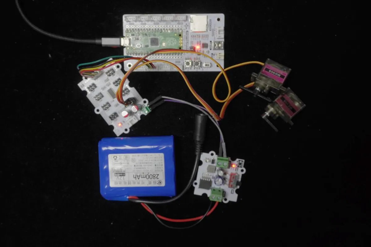
To make multiple servos "follow instructions", it is necessary to separate the wiring of the signal loop, the power supply loop and the servo connection respectively:
2.1 Signal Loop (Development Board ↔ Servo Driver Module)
This part transmits the control commands for the development board, requiring only 2 I2C wires. We connect the 16-channel PWM servo driver module via the I2C bus to the I2C interface I2C0 of the development board, and the corresponding relationship is as follows:
connection object | Development Board Pins | Module Pins | Description |
Development Board and Module ( | Pin 4 |
| I2C data transmission line, corresponding to |
Development Board and Module ( | Pin 5 |
| I2C clock signal line, corresponding to |
2.2 Power Supply Circuit (Power Supply ↔ Servo Drive Module)
This part supplies operating current to the modules and servos (servos require a relatively large current, so it is recommended to use an external 5V power supply for independent power supply).
power supply | Module Pins | Description |
5V power supply positive electrode | VIN | The positive power supply terminal of the module and the servo |
5V Power Supply Negative Terminal (GND) | GND | The power supply negative terminals of the module and the servo need to be connected to the GND of the development board |
2.3 Servo Connection (Servo Driver Module ↔ Servo)
Connect two 180° servos to the output channels of the module:
servo | Module Channel | Description |
Servo 1 |
|
|
Servo 2 |
|
|
📌 Note
- The default I2C address of the module is
0x40, which can be switched via the address pins. Up to 62 modules can be cascaded to control thousands of servos! - Connect the red wire of the servo to the module's VIN (5V), the brown wire to GND, and the orange wire to the signal pin of the corresponding channel.
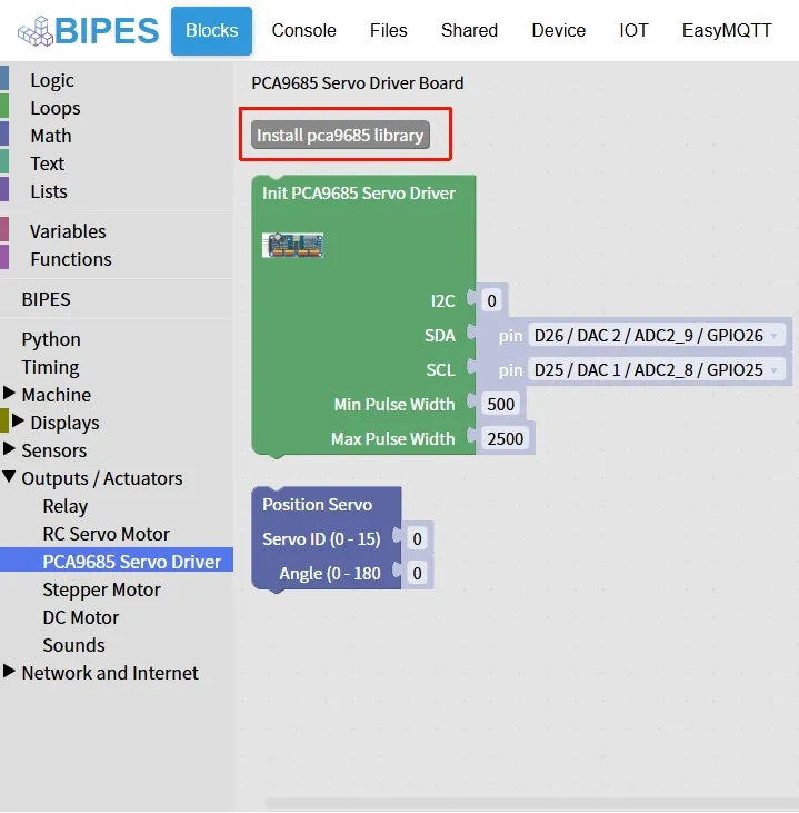
3. Install the PCA9685 library function
Before using graphical building blocks, you need to install the driver library first:
4. Example: Demonstration of Cooperative Rotation of Dual Servos
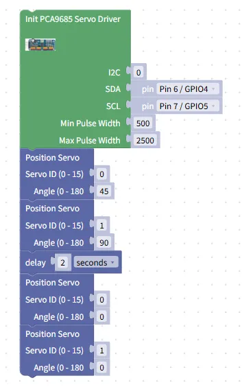
Experiment Objective: Make the servo connected to IO1 (Channel 0) rotate to 45°, the servo connected to IO2 (Channel 1) rotate to 90°, reset both to 0° simultaneously after a 2-second pause, so as to intuitively experience the effect of multi-servo coordinated control.
Everyday Life Insight: A robot arm can bend multiple joints at the same time, which is achieved through the coordinated control of multiple servo motors. Now let's build a prototype of a "double-joint robot arm"!
The graphical program is as follows:
Building Block Assembly Steps:
- Initialize the servo drive
- Drag in
Init PCA9685 Servo Driverblock; - Set
I2Cto0(corresponding to the I2C0 interface); SDAselectsPin 6 / GPIO4,SCLselectsPin 7 / GPIO5, which matches the wiring.- Set the
Min Pulse Widthto500, and set theMax Pulse Widthto2500(this is the pulse range adapted for 180° servos).
- Drag in
- Control the rotation of the servo
- Drag in
Position Servoblock; - Set
Servo ID (0-15)to0(corresponding to the servo of IO1),Angle (0-180)to45; - Drag in another
Position Servoblock; - Set the
Servo IDto1(corresponding to the servo of IO2), and set theAngleto90.
- Drag in
- Set dwell time
- Drag in the
delayblock and set it to2seconds → Make the servo stay at the target angle for 2 seconds.
- Drag in the
- Steering gear reset
- Drag in
Position Servoblock, setServo ID 0'sAngleto0; - Drag in another
Position Servoblock, and setServo ID 1'sAngleto0.
- Drag in
Experimental Effect:
C2178.MP4 72.0 MB
- After the program runs, the servo of IO1 will slowly rotate to 45°, and the servo of IO2 will rotate to 90°;
- After staying for 2 seconds, the two servos reset to 0° simultaneously;
- During the whole process, the two steering gears operate in coordination, with smooth rotation and precise angles.
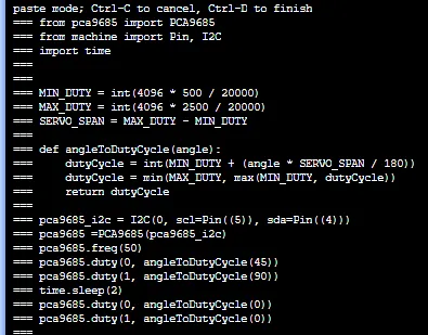
Graphical blocks will be automatically converted into MicroPython code, and the running results will be displayed:
Directly importable building blocks:
Servo.xml 4 KB
Tips
- If the servo does not rotate / rotates abnormally:
- Check the signal wiring: verify whether the SDA and SCL pins are connected correctly, and whether there is any I2C address conflict;
- Check power supply: Ensure that the 5V power supply for the module and the servo is sufficient (the servo draws high current, so an external power supply is recommended);
- Check the wiring of the servo motor: connect the red wire to VIN, the brown wire to GND, and the orange wire to the signal pin; do not reverse the connections.
- Advanced Gameplay:
- Add more servos to realize the multi-joint linkage of the robot arm;
- Pair it with a sensor (such as an infrared distance sensor) to enable the servo to automatically adjust its angle based on the sensor data.
✨ Interactive Quiz
- Think about it: Why can the PCA9685 control 16 servos simultaneously? Without using this module, what is the maximum number of servos that can be controlled directly with the pins of a development board?
- Try it: Change the servo angles to 60° and 120°, and see how the rotation effect changes. Then adjust the delay time to make the movement smoother.
Summary
- The 16-channel PWM servo driver module based on the PCA9685 over the I2C bus is a core module for multi-servo control that enables a development board to control up to 16 servos with just 2 wires.
- It enables precise and coordinated control of multiple servos via I2C communication and PWM output, making it an essential tool for robot and robotic arm projects.
- The basic usage follows the sequence of "initialization → angle control → delay → reset", while the advanced usages include multi-servo linkage and intelligent control;
- Pay attention to the power supply stability of the servo; an external power supply enables the servo to rotate with greater force and more stability.