
Contents
- 1. Module Introduction
- 1.1 Infrared Transmitting Module
- 1.2 Infrared Receiving Module (TSOP34138)
- 2. Wiring Instructions
- 2.1 Infrared Transmit Module Based on IR333C (Connected to DIO2)
- 2.2 Infrared receiving module based on TSOP34138 (connected to DIO0)
- 3. Example: Infrared Signal Transceiver Demonstration
Young makers, today let's unlock a "secret walkie-talkie that can send and receive invisible light signals" 🔮!
When you press a button on a TV remote control, it emits an invisible infrared light signal, and the receiving sensor inside the TV will "pick up" the command and execute it. The infrared receiver module based on TSOP34138 paired with the infrared transmitter module we use today acts like an "infrared walkie-talkie" for the development board, enabling it to transmit and receive invisible infrared signals — it’s incredibly cool for building infrared remote controls, obstacle-avoidance cars and more ✨!
1. Module Introduction
1.1 Infrared Transmitting Module
At its core is an infrared LED that emits infrared light invisible to the human eye. To avoid interference from natural light, it uses a 38kHz high-frequency signal to modulate the infrared light (much like "encrypting" the infrared light), so that the receiving module only recognizes signals of this frequency.
1.2 Infrared Receiving Module (TSOP34138)
This is a receiver module specifically designed to "listen" for 38kHz infrared signals. It automatically demodulates the signals embedded in infrared light, converting the encoded infrared light into electrical signals recognizable by the development board. When a matching infrared signal is received, the output pin will transition from a high level to a low level, triggering an interrupt or detection event.
Features of their coordination:
- 🔒 Strong anti-interference: The 38kHz modulation ensures that the signal will not be interfered by sunlight or artificial light;
- 📶 Stable transmission: Infrared light travels in a straight line, making it suitable for short-range (1-10 meters) wireless communication;
- 🎮 Diverse gameplay: It can be used to make projects such as infrared remote controllers, infrared obstacle avoidance devices, interactive toys, etc.
These blocks are commonly used in graphical programming:
set output pinBlock: Controls the high and low levels of the infrared transmitting module to simulate a 38kHz modulated signal;External Event (Interrupt on Input Pin)Block: The infrared receiving module uses interrupt to detect signals, and executes actions when triggered;repeat while trueBlock: continuously emit infrared signals;printBlock: Outputs a trigger prompt.
2. Wiring Instructions
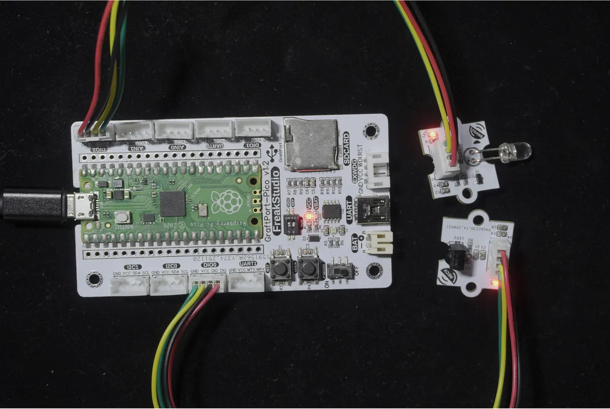
2.1 Infrared Transmit Module Based on IR333C (Connected to DIO2)
Responsible for transmitting infrared signals modulated at 38kHz.
Development Board Pins | Module Pins | Description |
Pin 6 |
| Infrared signal transmission output pin |
Pin 7 |
| - |
2.2 Infrared receiving module based on TSOP34138 (connected to DIO0)
Responsible for receiving and demodulating infrared signals.
Development Board Pins | Module Pins | Description |
Pin 14 |
| - Infrared signal receiving input pin |
Pin 15 |
| - |
📌 Note
- The transmitting module and the receiving module must be aligned with no obstruction in between; otherwise, the signal cannot be transmitted.
- 38kHz is the standard frequency for infrared remote controls, and most home appliance remote controls operate at this frequency.
3. Example: Infrared Signal Transceiver Demonstration
Experiment Objective: Make the infrared transmitting module continuously transmit analog infrared signals of 38kHz; when the receiving module detects the signal via interrupt, print "Infrared Triggered" on the terminal to intuitively experience the effect of "invisible optical communication".
Everyday Life Insight: The communication between a TV remote control and a television works on this exact principle. Now let's build our own "mini infrared remote control and receiver"!
The graphical program is as follows:
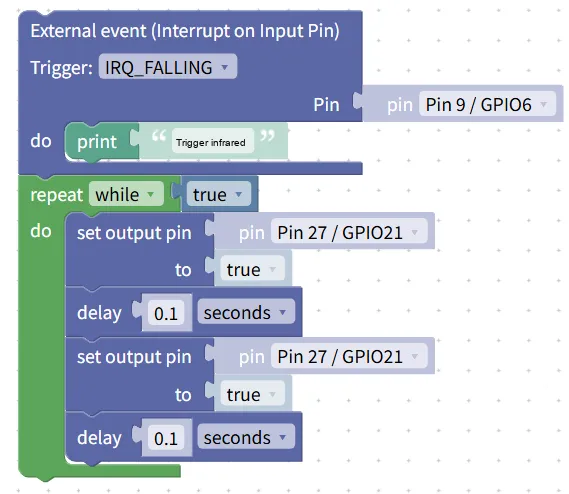
Building Block Assembly Steps:
🔴 Infrared Transmitter Section (Continuous Signal Transmission)
- Infinite Loop Firing
- Drag in the
repeat while trueblock to keep the launch module working continuously;
- Drag in the
- Simulated 38kHz modulated signal
- Drag in
set output pinblock, selectPin 27 / GPIO21, and set it totrue; - Drag in the
delayblock and set it to0.1second (simulate the high level of a high-frequency pulse); - Drag in another
set output pinblock, selectPin 27 / GPIO21, and set it tofalse; - Drag in the
delayblock and set it to0.1seconds (simulating the low level of a high-frequency pulse); - (Note: The actual 38kHz corresponds to a period of 1/38000 ≈ 26μs; the 0.1 second used here is for simplified demonstration, and a real project requires PWM to output a 38kHz signal)
- Drag in
🟢 Infrared receiving section (interrupt detection signal)
- Configure external interrupts
- Drag in
External event (Interrupt on Input Pin)block; - Set the
TriggertoIRQ_FALLING(triggered when a high-to-low signal transition is detected); - Selected Pin:
Pin 9 / GPIO6;
- Drag in
- Trigger Feedback
- When an interrupt is triggered, add the
print "Infrared triggered"block.
- When an interrupt is triggered, add the
Experimental Effect:
- The transmitting module continuously transmits infrared signals, with the transmitting head aligned with the receiving head;
- After the receiving module detects a signal, the terminal immediately prints "Trigger infrared";
- Block the optical path between the transmitter and the receiver, and printing will stop; printing will resume after the obstruction is removed.
Graphical blocks will be automatically converted into MicroPython code, and the running results will be displayed:
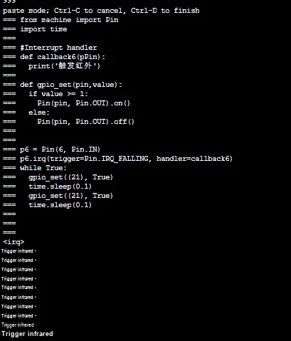
Directly importable building blocks:
Tips
- 🔔 Safety Reminder:
- Do not look directly at the infrared emitter; although infrared light is invisible, high-power emission may cause eye damage.
- Keep the transmitting and receiving heads clean to prevent dust from blocking the optical path.
- 🛠️ Debugging Tips:
- Weak signal / No reception: Ensure that the transmitter and receiver are aligned, and the distance between them does not exceed 10 meters;
- Frequent false triggers: Keep away from strong light sources (such as sunlight, table lamps) to avoid interfering with infrared signals;
- For real projects, it is recommended to use PWM to output a 38kHz signal (for more accurate frequency) instead of simulating it with high and low levels.
- 🎮 Advanced Gameplay:
- Add encoding (e. g. NEC code) to the infrared signal to make an infrared remote control capable of controlling multiple functions;
- When paired with a servo or LED, it can control the rotation of the servo or the on/off state of the LED via infrared signals.
✨ Interactive Quick Question
- Think about it: Why is 38kHz modulation used for infrared signals? What problems will arise with unmodulated infrared signals?
- Try this: Move the transmitter and receiver 5 meters apart and check if the signal can still be received. Then block the optical path with a book and observe whether the signal is interrupted.
Summary
- The infrared transceiver module based on TSOP34138 is an invisible optical communication module that enables short-distance wireless signal transmission;
- The transmitting module uses 38kHz modulated infrared light, and the receiving module demodulates the signal, delivering strong anti-interference performance;
- The basic usage is simple communication of "simulated transmission + interrupt reception", while the advanced usage is to add encoding to implement complex remote control;
- It is a core module for infrared remote control, obstacle avoidance, and interactive toys, enabling development boards to have the capability of "wireless control".