
Contents
Young makers, today let's unlock a "safe switch capable of controlling high current" 🔌!
The pins of a development board can only withstand small currents and cannot directly drive high-current devices such as motors and bulbs. However, a common relay module based on the HF46F acts like a "remote control for high-current devices": the development board only needs to send a weak electrical signal to make it snap closed, thereby connecting the high-current circuit — it is both safe and reliable ✨!
1. Module Introduction
Want to make power-hungry devices like motors and bulbs follow the commands of your development board? A relay is your go-to "safety assistant" for this job!
It is an electromagnetic switch module with the compact HF46F electromagnetic relay as its core component: when the development board inputs a low-current signal to the relay, the internal electromagnet will pull in the contacts to close the high-current circuit (such as the power supply for a motor); when the signal is cut off, the electromagnet releases, the contacts spring open, and the high-current circuit is disconnected accordingly. Simply put, it is a "switch that controls high current with low current".
Compared with direct drive, it has the following characteristics:
- 🛡️ Electrical Isolation: The development board only outputs low-level signals and does not come into direct contact with high current, completely eliminating the risk of burnout;
- ⚡ Strong driving capability: capable of controlling devices that require high current such as motors and bulbs;
- 🎮 Simple control: Just like controlling an LED, you can toggle the switch "on/off" simply with "high/low level";
- 🧩 Wide range of application scenarios: suitable for projects such as motor control, light switching, home appliance remote control, etc.
In graphical programming, these blocks are commonly used for relays:
set output pinBlock: controls the relay to pull in / release;delayblock: controls the operating duration of the device;- Sequential execution block: implements simple control of "start → delay → stop".
In practical projects, it is often used for the following purposes:
- Motor controller (e. g., to make the car motor run for 5 seconds and then stop)
- Light switch (e. g., turning lights on/off triggered by a sensor)
- Home appliance remote control (e. g., controlling the power supply of small fans, small table lamps)
Popular Science: What is an Electromagnetic Relay?
A relay contains an electromagnet and a set of metal contacts inside. When the development board supplies power to the electromagnet, the electromagnet generates magnetic force to pull in the contacts, just like pressing the "power switch" of a high-current device; when the power is cut off, the magnetic force disappears, the contacts spring open, and the device is powered off. Throughout this process, the development board only acts like "pressing a remote control" and never directly touches the "high-current socket", making it extremely safe!
2. Wiring Instructions
To make a relay "obedient", the first step remains the same: connect the wires correctly!
We will connect in the following manner:
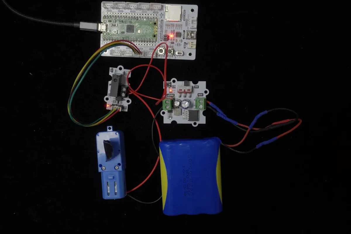
We will connect the common relay module based on HF46F to the digital interface DIO0 of the development board, and the corresponding relationship is as follows:
Development Board Pins | Module Pins | Description |
Pin 6 |
| The pins connected to the MCU output high and low levels. |
Pin 7 |
| - |
- The power supply outputs
5Vvoltage, which is divided into two lines: the positive pole andGND(negative pole). - The positive terminal of the power supply is connected to node
A, serving as the positive input terminal of the power supply backbone. - The positive terminal of the motor (motor +) is not directly connected to the power supply, but is connected to the output terminal of the relay.
- Power Supply
GNDis directly connected to the negative terminal of the motor (Motor -) to form the foundation of the circuit.
📌 Note
- When the development board outputs a high level (true), the relay pulls in, the contacts close, and the motor starts to rotate;
- When outputting a low level (false), the relay is de-energized, the contacts open, and the motor stops rotating.
3. Example: Control the motor to stop after rotating for 5 seconds
Test Objective: Energize the relay for 5 seconds to drive the motor to run for 5 seconds before automatically stopping, so as to intuitively experience the safety effect of "small signal controlling large current".
Everyday Insight: The smart plug at home lets you control the on/off of appliances via your phone, which works on a relay principle similar to this. Now let's make a "tiny switch that can control a motor on a timer" ourselves!
The graphical program is as follows:
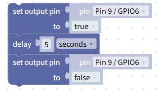
Building Block Assembly Steps:
- Pull-in Relay (Starter Motor)
- Drag in the
set output pinblock; - Selected Pin:
Pin 9 / GPIO6(corresponding to DIO0 interface); - Set to
true→ the relay closes and the motor starts running;
- Drag in the
- Set rotation duration
- Drag in the
delayblock and set it to5seconds → make the motor rotate continuously for 5 seconds;
- Drag in the
- Release the relay (stop the motor)
- Drag in another
set output pinblock; - Pin retention
Pin 9 / GPIO6; - Set to
false→ the relay is de-energized and the motor stops running.
- Drag in another
Experimental Effect:
C2177.MP4 64.0 MB
- After the program runs, the relay will click closed and the motor will start rotating immediately;
- After 5 seconds, the relay clicks and releases, and the motor stops automatically;
- Throughout the entire process, the development board only outputs small signals and fully isolates high currents, ensuring safety and stability.
Graphical blocks will be automatically converted into MicroPython code, and the running results will be displayed:
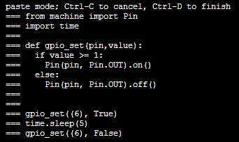
Directly importable building blocks:
Relay (2).xml 2 KB
Tips
- If the relay fails to pull in / the motor does not rotate:
- Check whether the pins are selected correctly (
Pin 9 / GPIO6) and whether the wiring is secure; - Verify that the 5V power supply is normal and check whether the motor is stuck by foreign objects;
- Listen for a "click" sound of the relay pulling in; if there is no such sound, check whether the control signal is normal.
- Check whether the pins are selected correctly (
- Safety Note:
- Relays control high-current equipment. Always disconnect the power supply before wiring to avoid electric shock;
- Do not use a relay to control devices with a current exceeding its rated current (the maximum current of HF46F is typically 1A).
- Advanced Gameplay:
- When paired with a touch key module, it realizes the function of "start the motor as soon as touched, stop it as soon as released";
- Paired with a light sensor, it will automatically engage the relay to turn on the light when the ambient light is dim.
✨ Interactive Quiz
- Think about it: Why can't we directly use the pins of the development board to drive the motor, but have to use a relay instead?
- Try it: Change the delay time from 5 seconds to 10 seconds, and see what changes will happen to the motor rotation duration? Then change it to 2 seconds to experience different control effects.
Summary
- The common relay module based on HF46F is an electromagnetic switching module that can realize "controlling high current with small signals";
- It switches the contacts on and off via electromagnetic attraction and release, providing safe isolation between the development board and high-current devices to prevent the development board from being burned out.
- The basic application is simple control following the sequence of "pull-in → time delay → release", while the advanced application enables smart switching in combination with sensors;
- It is an essential module for controlling high-current devices such as motors and lights, which is safe and practical.