
Contents
Young makers, today let's unlock a "little helper to cool down the development board" 🌬️!
The fans that whir loudly when a computer runs games, and the cooling fans in power banks during fast charging, all serve to cool down the devices. Today we are going to learn about the MOSFET-based cooling fan module ✨, which enables the development board to control the fan speed, giving your hardware a "cool breeze" to prevent overheating!
1. Module Introduction
When we use a development board to drive high-power modules (such as high-power LEDs and motors), the hardware tends to generate heat, and a cooling fan is required to lower the temperature in this case.
It is a type of execution output module, whose core component is a MOSFET (electronic switch): the current required by a fan is much higher than what a development board pin can supply. The MOSFET acts as a "current bridge" — it uses the small signals (PWM or high/low levels) output by the development board to control high current, which not only protects the development board, but also enables stable fan operation, and supports PWM speed regulation.
Compared with ordinary direct-drive fans, it has the following features:
- 🌬️ Efficient heat dissipation: The fan delivers moderate airflow that quickly removes heat from hardware;
- 🎛️ Adjustable speed: Supports precise PWM speed adjustment, with continuous variation from gentle breeze to strong wind;
- 🔌 Safe and Reliable: MOSFET isolates high current to prevent the development board from being burned out;
- 🧩 Flexible installation: It can be attached next to the heating module for targeted heat dissipation.
In graphical programming, these blocks are commonly used for cooling fans:
count withloop block: generates continuously varying values, used to adjust the rotational speed;PWM #6Building Blocks: Configure the pins, frequency and duty cycle (speed) of the fan;printblock: Output the duty cycle value of the current rotational speed;delayblock: controls the speed of rotational speed changes.
In practical projects, it is often used for the following purposes:
- Hardware heat dissipation devices (e. g., for cooling high-power LEDs and motors)
- Temperature-controlled fan (equipped with a temperature sensor, which automatically activates when overheating occurs)
- Interactive wind-powered toys (e. g., controlling wind speed to blow up small pieces of paper)
Popular Science: Why Use MOSFETs to Drive Fans?
A fan requires a relatively large current (e. g., several hundred milliamperes) when operating, while the pins of a development board can only output a current of several tens of milliamperes. Direct connection will burn out the pins. A MOSFET can control a large current with a small current signal, just like using a small key to open a large sluice gate, which is not only safe but also enables the fan to work properly.
2. Wiring Instructions
To get the fan "spinning", the first step remains the same — connect the module correctly!
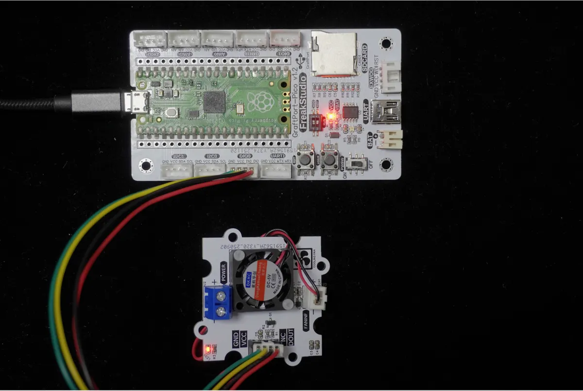
We will connect the MOSFET-based cooling fan module to the digital interface DIO0 of the development board, with the corresponding relationship as follows:
Development Board Pins | Module Pins | Description |
Pin 6 |
| - |
Pin 7 |
| - |
📌 Note
- When the development board outputs a PWM signal, the MOSFET adjusts the fan current according to the duty cycle: the larger the duty cycle (the higher the value), the faster the fan speed;
- When the duty cycle is 0, the fan stops rotating.
3. Example: PWM Adjustment of Fan Speed (Gradual Change from Slow to Fast)
Experimental Objective: Start the fan from a stationary state, gradually increase its speed slightly every 3 seconds until reaching the maximum rotational speed, and meanwhile print the current duty cycle value in the terminal to intuitively experience the effect of PWM speed regulation.
Everyday Insight: The fan of a laptop automatically adjusts its speed based on the CPU temperature, which is realized via PWM Technology Implementation. Now let's make a "small fan with automatic speed regulation" ourselves!
The graphical program is as follows:
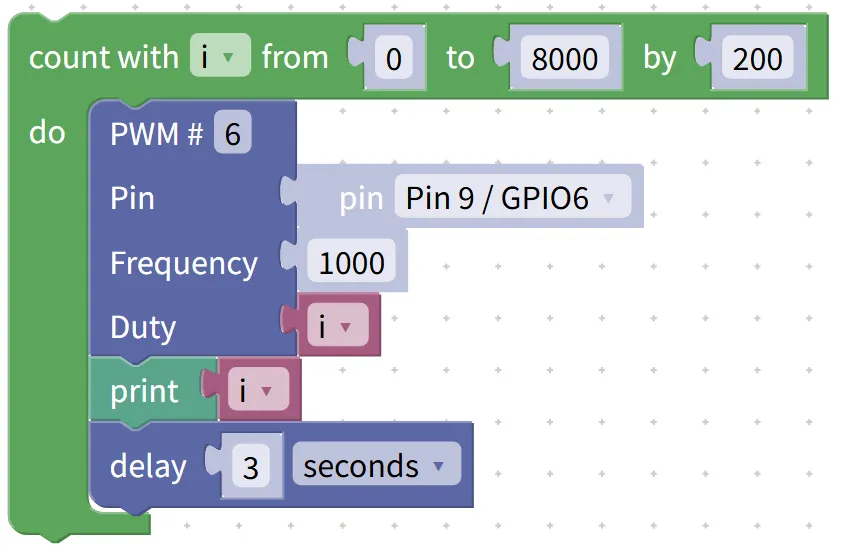
Building Block Assembly Steps:
- Generate gradually changing rotational speed values
- Drag the
count with i from 0 to 8000 by 200block in; - Let the variable
istart from 0, increment by 200 each time until it reaches 8000, to simulate the change of rotational speed from zero to the maximum.
- Drag the
- Configure PWM output
- Drag the
PWM #6block into the loop; - Selected Pin:
Pin 9 / GPIO6; - Set the
Frequencyto1000(1000 switches per second for smoother speed adjustment); - Set
Dutytoi(use variable i to control the duty cycle and achieve speed variation).
- Drag the
- Print the rotational speed value
- Add the
print iblock to display the current duty cycle value in the terminal.
- Add the
- control the rate of change
- Drag in the
delayblock and set it to3seconds → This makes the rotational speed change more gradual, making it easier to observe the change in the fan's rotational speed.
- Drag in the
Experimental Effect:
- After the program runs, the fan will start from a completely stationary state, and its rotational speed will increase slightly every 3 seconds until it reaches the maximum wind speed;
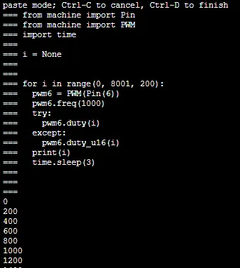
- The terminal will synchronously print the duty cycle value for each time (0,200,400…8000);
- The rotational speed changes continuously and smoothly throughout the entire process, with no laggy feeling.
Graphical blocks will be automatically converted into MicroPython code, and the running result will be displayed:
Directly importable building blocks:
Fan.xml 3 KB
Tips
- If the fan does not rotate:
- Check if the correct pin is selected (
Pin 9 / GPIO6) and whether the wiring is secure; - Confirm that the module is properly powered and check whether the fan is blocked by foreign objects;
- Check if the correct pin is selected (
- What should I do if the rotational speed is insufficient?
- You can increase the maximum value of
count withfrom 8000 to a larger number (e. g., 10000) to increase the duty cycle;
- You can increase the maximum value of
- Advanced Gameplay:
- Paired with a temperature and humidity sensor module, it will automatically start the fan when detecting excessive temperature, forming a "temperature-controlled heat dissipation system";
- Use the value of the sliding rheostat to control the PWM duty cycle, so as to realize a "manually speed-adjustable fan".
✨ Interactive Mini Quiz
- Think about this: Why do fans require PWM speed control instead of being directly controlled by high and low levels to switch between "on (spinning)" and "off (stopped)"?
- Try this: Change the
delaytime from 3 seconds to 1 second, and see whether the fan speed change will become faster or slower?
Summary
- The MOSFET-based cooling fan module is an execution-type output module that drives the fan via MOSFET to achieve heat dissipation;
- It supports PWM speed regulation, which can realize continuous change from standstill to maximum rotating speed, making it suitable for projects such as hardware heat dissipation and temperature-controlled fans;
- The basic usage is to realize automatic speed regulation through "loop + PWM", while the advanced usage is to realize intelligent heat dissipation in combination with sensors;
- It is a practical module for protecting hardware and learning PWM speed regulation.