
Contents
- 1. The Lively "Mini Classroom"
- 1.1 Questions about daily life scenarios
- 1.2 Understand I2C in a Nutshell
- 1.3 Interactive Mini-Discussion
- 2. Understand the "Classroom Rules" of I2C
- 2.1 SDA/SCL Lines
- 2.2 Device Address
- 2.3 Interactive Mini Exercise
- 3. Complete Analysis of I2C Building Blocks
- 3.1 Initialization Block (I2C.init) —— Set up the classroom and enable the chat mode between teachers and students
- 3.2 Turn off the block (I2C.deinit) — End the class and stop the communication between the teacher and students
- 3.3 Device Scanning Block (I2C.scan) —— Just like a teacher taking attendance to check which students (devices) are present in class
- 3.4 Communication Start Block (I2C.start) —— Just like a teacher calling "class begins" to start interacting with students
- 3.5 Communication Stop Block (I2C.stop): When the teacher says "class dismissed", it pauses the communication with the students
- 3.6 Store Data into the Building Block (I2C.readinto): Guide students to write the data into their notebooks
- 3.7 Command Sending Block (I2C.write): The teacher sends a command to the student with the specified student ID
- 3.8 Data Reading Block (I2C.readfrom) —— Instruct the student with the specified student ID to report data
- 3.9 Read Student Notebook Block (I2C.readfrom_mem) —— Instruct the specified student to take out their dedicated notebook and read the content inside
- 3.10 Student Note Copying Block (I2C.readfrom_mem_into) — Copy the content from the student's notebook to the teacher's notebook
- 3.11 Write to Student Notebook Block (I2C.writeto_mem) —— The teacher writes new instructions in the dedicated notebook of the specified student
I2C is another commonly used communication method, which is particularly suitable for one-to-many scenarios. You can think of it like this: a teacher communicates with multiple students at the same time in class without having to pull a separate line for each student, which is extremely efficient!
1. The Lively "Mini Classroom"
1.1 Questions about daily life scenarios
Think about this: How can a teacher talk to each student individually at the same time in one classroom without getting into chaos?
- The teacher only uses one "sound line"(to convey content) and one "rhythm line"(to control the pace), which are shared by the entire class;
- Each student has a unique "student ID number" that will not be duplicated;
- The teacher will call out the student numbers first; after the corresponding student responds, the one-on-one conversation will begin, and the other students should listen quietly as observers.
This is the core concept of I2C communication: the development board (the teacher) and multiple peripherals (the students) share a single "communication bus", eliminating the need for separate wiring for each peripheral. The main controller can accurately access each slave device individually, which is both wiring-saving and highly efficient.
1.2 Understand I2C in a Nutshell
The development board acts as the "teacher", and the multiple peripherals serve as the "students";with just two wires, you can set up the "classroom". The teacher can either call on a specific student to speak individually, or send announcements to the entire class at once.
1.3 Interactive Mini-Discussion
What devices in daily life use this "one-to-many chat" method?
Reference answer: The sensor cluster in a smartwatch, the multiple indicator lights on a router, and the combination of the OLED screen and temperature-humidity sensor on a development board — all these are examples of one main controller driving multiple peripherals.
2. Understand the "Classroom Rules" of I2C
Just as a classroom requires discipline, I2C communication also has 3 mandatory rules to follow — miss even one, and everything will descend into total chaos and loss of control!
2.1 SDA/SCL Lines
The core reason why I2C can save wires lies in these two "shared lines", which have clear division of labor and will not conflict with each other:
- SDA Line (Serial Data): the "data transmission line", which is dedicated to transmitting specific data (such as what the teacher says, students' responses, or correspondingly, the instructions sent by the development board and the detection data returned by peripherals);
- SCL Line (Serial Clock): the "attention line" that synchronizes the communication rhythm — just like a teacher tapping the blackboard to set the pace: "One, two, speak!" — ensuring the master and slave devices "speak at the same speed" so that no data transmission errors occur.
Analogy extension: If the teacher (development board) speaks too fast for the students (peripheral devices) to keep up, they will miss what is being said; the SCL line acts as a "metronome" — with each beat, one data bit is transmitted, and as long as both parties follow the rhythm strictly, even the most complex data will not be messed up.
2.2 Device Address
Every I2C peripheral has a unique "address"(similar to a student ID number), which is the key to enabling "one-to-one addressing" in I2C:
- Before the development board sends a command, it first "broadcasts the address" on the bus. All peripherals will listen to the bus, only the peripheral with the matching address will respond, and the rest will remain silent.
- There are two types of addresses: ① Fixed addresses (used by most basic peripherals such as ordinary OLED displays and DHT11 temperature and humidity sensors; the address is set at the factory and cannot be modified); ② Modifiable addresses (adopted by some advanced peripherals, whose addresses can be adjusted by connecting different pins to avoid conflicts).
2.3 Interactive Mini Exercise
If two students have the same student ID (i. e., two I2C peripherals share the same address), will the teacher mistake one for the other?
- Answer: Yes! The communication will go completely wrong: either the data gets lost, or garbled messages are received. It’s just like when a teacher calls out student number "25" and two students respond at the same time—their voices mix together and become totally unintelligible.
Quick reminder: When building an I2C multi-device circuit, first check the default address of each peripheral to ensure there is no duplicate; if duplicates exist, adjust them using peripherals with modifiable addresses.
The core of I2C communication lies in " two wires, multiple devices, and address-based addressing ", which operates efficiently and orderly like a teacher leading students. It helps us solve the problem of "numerous peripherals but limited interfaces", making it the most commonly used communication method in comprehensive projects. You will definitely use it when building complex systems later, such as simultaneously monitoring temperature, humidity, and light while displaying the data. ~
3. Complete Analysis of I2C Building Blocks
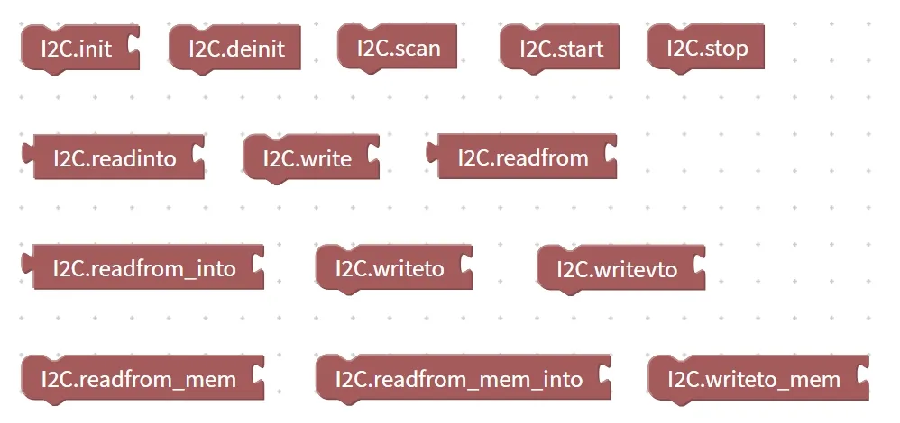
3.1 Initialization Block (I2C.init) —— Set up the classroom and enable the chat mode between teachers and students
Young makers, I2C communication is just like the "teacher-student interaction" in a classroom. Before the communication starts, we need to set up the classroom and arrange the seats properly so that both the teacher and students can hear each other clearly. The initialization block is the first step to set up the classroom, which gets the I2C bus ready for data transmission.

Chinese meaning: Initialize the I2C bus, configure the SCL (clock line) and SDA (data line) pins of the main control board to prepare for I2C communication.
Core Features:
- Set pins: Tell the development board which wire is SCL (clock line) and which one is SDA (data line);
- Enable the bus: Once initialization is complete, the I2C bus will be ready to transmit and receive data;
- Must be used first: All subsequent I2C device operations depend on this initialization;
Example in daily life:
- Classroom setup: Arrange the desks, chairs and blackboard first so that teachers and students can have classes smoothly;
- Preparation for a conference call: First connect the line, turn on the microphone and speaker, so that the call can proceed smoothly;
- Set up the venue before the party: Prepare the lighting, sound system and seating so that guests can interact upon arrival.
Practical Example 1: Initialize the I2C Bus
- Requirement: Prepare to connect the OLED display module
- Step 1: Use the I2C.init block to set the SCL pin to
5and the SDA pin to4; - Step 2: After initialization is complete, you can use the display blocks to control the OLED;
- Logic description: The initialization block is equivalent to "setting up the classroom properly", and only after the setup is completed can the bus transmit and receive data.
Practical Example 2: Connecting Multiple I2C Devices After Initialization
- Requirement: Use both an OLED display and a temperature & humidity sensor simultaneously
- Step 1: Use I2C.init to configure the bus pins;
- Step 2: Operate each I2C device block in sequence;
- Logic Description: An I2C bus can be connected to multiple devices simultaneously, but the bus must be initialized first.
Quick Reminder
- Initialize first before operating the device — the order is extremely important;
- The SCL/SDA pins must be correct; otherwise, the device cannot communicate normally.
- The I2C bus supports multiple devices, but their addresses must not be duplicated, otherwise a conflict will occur;
- Only needs to be initialized once, unless the device is restarted or the pin settings are modified.
✨ Exclusive Mini Interaction
- Quick Response 1: What is the core function of the I2C.init block? (Answer: Initialize the I2C bus, configure the SCL/SDA pins, and prepare for communication)
- Think about it: If you forget to initialize I2C, can the bus devices work properly? (Answer: No, communication cannot proceed.)
- Scenario-based Judgment: When connecting both an OLED and a temperature-humidity sensor at the same time, why is only one initialization required? (Answer: All devices on the same bus share the SCL/SDA pins, so the pins only need to be configured once.)
- Mini Challenge: Try to initialize I2C, connect an OLED display to show "Hello", and observe the display effect.
Summary:
- Initialization block (I2C.init): Set up the "classroom" for the I2C bus to enable communication between devices;
- Must be used before operating any I2C device, and ensure that the SCL/SDA pins are correctly connected;
- After initialization, the I2C bus can be connected to multiple devices simultaneously to transmit and receive data smoothly.
3.2 Turn off the block (I2C.deinit) — End the class and stop the communication between the teacher and students
Young makers, the I2C bus is just like a classroom in session: the initialization block sets up the "classroom" so that teachers and students can communicate smoothly. When the class is over or the I2C is not in use temporarily, we need to suspend the class and tidy up the classroom to avoid bus conflicts or resource waste. The shutdown block is designed for this step, which safely stops the I2C bus from working.

Chinese meaning: Shut down the I2C bus, release the SCL/SDA pins, so that the development board no longer communicates with I2C devices.
Core Features:
- Stop bus: The I2C bus will no longer transmit or receive data;
- Release pins: The SCL/SDA pins return to an idle state and can be used for other functions or re-initialization;
- Safe operation: Prevent bus conflicts or equipment malfunction;
Example in daily life:
- Tidying up the classroom after class: Teachers and students put away their books, turn off the lights, and walk out of the classroom;
- Hang up the call: Release the line and free up resources once the call ends;
- End Meeting: Terminate the video conference and turn off the microphone and camera.
Practical Example 1: Turn off the I2C bus after class
- Requirement: Turn off the bus after the OLED display finishes
- Step 1: Initialize I2C, and the bus transmits display data;
- Step 2: After the display is complete, use the I2C.deinit block to turn off the bus;
- Logic description: Turning off the blocks is just like tidying up the classroom — it releases the pins and gets the development board ready for the next operation.
Practical Example 2: Temporarily Switching I2C Pins
- Requirement: Originally, SCL= 5 and SDA= 4 were used, and now we want to switch to SCL= 21 and SDA= 22
- Step 1: First use I2C.deinit to disable the original bus;
- Step 2: Reinitialize the new pins using I2C.init;
- Logic description: Turn off the building block to ensure the pins are idle, avoid pin conflicts, and switch the bus smoothly.
Quick Reminder
- Stop and then reinitialize to ensure safe pin switching;
- Turning off the bus will not delete data; it only stops communication.
- After the bus is shut down, all I2C devices will fail to respond, and re-initialization is required for subsequent communication;
- Develop good habits: Power off the I2C peripheral in time when it is not in use to prevent the bus from being occupied.
✨ Exclusive Mini Interaction
- Quick Response Quiz 1: What is the core function of the I2C.deinit block? (Answer: To shut down the I2C bus and release the SCL/SDA pins)
- Think about it: What will happen if you initialize a new pin without disabling the bus first? (Answer: Pin conflicts may occur, leading to communication failure.)
- Scenario Judgment: After the display finishes its operation, if you want to temporarily use the SCL/SDA pins to control other devices, what should you do first? (Answer: First use I2C.deinit to disable the bus)
- Small challenge: Try turning off the bus after the OLED display finishes outputting content, then reinitialize the display to show other content, and observe the result.
Summary:
- Deinitialize the block (I2C.deinit): End the "session" of I2C communication and release the bus and pins;
- It must be used when I2C is no longer in use or reinitialization is to be performed, so as to ensure safety and rational utilization of resources;
- After use, the bus device no longer responds and requires reinitialization to communicate properly.
3.3 Device Scanning Block (I2C.scan) —— Just like a teacher taking attendance to check which students (devices) are present in class
Young makers, the I2C bus is just like a lively classroom: the initialization block sets up the "classroom", and each I2C device is like a student sitting in the classroom. To confirm who is present and who is absent, we need to "call the roll". The device scanning block is the teacher's roll-calling tool that helps you check exactly which I2C devices on the bus have been properly connected.
Chinese meaning: Scan the I2C bus and return all detected device addresses (such as OLEDs, sensors, etc.) to let you know which devices are online.
Core Features:
- List device addresses: List all I2C device addresses connected to the bus;
- Facilitate debugging: Verify that the device is properly connected to avoid errors when operating the building blocks;
- Must be used after initialization: The bus is not initialized and devices cannot be detected;
Example in daily life:
- The teacher calls the roll to confirm which students are present and who is absent;
- Check meeting participants: The meeting software displays who is online and who is offline;
- Seat inventory check: Confirm that all equipment and items are in place before the event.
Practical Example 1: Scanning Devices on the Bus
- Requirement: Confirm whether the OLED and the temperature & humidity sensor are connected
- Step 1: Initialize the I2C bus (configure SCL/SDA pins);
- Step 2: Use the I2C.scan block to scan the bus;
- Step 3: The returned address list displays the OLED and sensor addresses to confirm that the devices are online;
- Logic explanation: Scanning the building blocks is just like a teacher taking attendance — it ensures all devices are in place so that subsequent operations can proceed smoothly.
Practical Example 2: Debugging Device Connection
- Requirement: The development board displays which I2C devices are connected to it
- Step 1: Initialize the I2C bus;
- Step 2: Use the scanning block to obtain the address list;
- Step 3: Print the result on the screen or via the serial port to confirm the device number;
- Logic description: If the device does not appear in the scan result, it indicates a wiring problem or an address conflict.
Quick Reminder
- Must be used after I2C initialization, otherwise scanning will not be possible;
- The scanning result is a list of device addresses, not device names, which requires confirmation in combination with the documentation;
- Multiple scans are supported to check for newly added or removed devices;
- Debugging the bus is of great importance, as it helps confirm whether the device is online.
✨ Exclusive Mini Interaction
- Quick Response 1: What is the core function of the I2C.scan block? (Answer: Scan the I2C bus and list all online device addresses)
- Think about it: If a certain device address is not found in the scan results, what could be the possible reasons? (Answer: The device is not connected, there is a wiring error, an address conflict occurs, or the bus is not initialized.)
- Scenario Judgment: If you connect an OLED and a temperature-humidity sensor at the same time, and the scan result shows two addresses, what does this indicate? (Answer: Both devices are normally online.)
- Mini Challenge: After scanning the bus, display the device addresses on the OLED to see which devices are "in the classroom".
Summary:
- Device scanning block (I2C.scan): It works like a teacher taking attendance, to confirm which I2C devices are already connected;
- Must be used after initializing the I2C bus, and returns a list of device addresses;
- The scan results are used for debugging and confirming that the device is online, helping ensure smooth subsequent block-based operations.
3.4 Communication Start Block (I2C.start) —— Just like a teacher calling "class begins" to start interacting with students
Young makers, the I2C bus is just like a classroom: the initialization block sets up the classroom, and the device scanning block checks which "students" are online. Next, the teacher will officially start the class and tell the students "it's time to start interacting". The communication start block is the signal for the teacher to call "class begins", which puts the bus into data communication mode.
Chinese meaning: Send a start signal on the I2C bus to inform all devices that the bus is ready for data transmission.
Core Features:
- Generate a start signal: the I2C bus enters the communication state;
- Prepare for data transmission: after which data can be sent or received;
- Must be used before each communication: It needs to be initiated before each transmission or reception;
Example in daily life:
- When the teacher calls out "Class begins", students know that they should listen attentively and answer questions.
- Before the meeting, the host announces the start: Participants know the meeting has officially begun;
- Race Start Command: Competitors shall not start the race until they hear the commands "Get set, go".
Practical Example 1: Starting Communication with the Device
- Requirement: Send display data to the OLED
- Step 1: Initialize the I2C bus and confirm that the device is online;
- Step 2: Use I2C.start to send a start signal;
- Step 3: Send a display command or read data;
- Logic description: Starting the block is like a teacher calling "Class begins", which means the device is ready to receive and respond to data.
Practical Example 2: Multi-device Communication
- Requirement: Control both the OLED and the temperature & humidity sensor simultaneously
- Step 1: Initialize I2C and perform a bus device scan;
- Step 2: Before sending data to a certain device each time, use I2C.start first;
- Step 3: After completing the operation, use I2C.stop to terminate the communication;
- Logic description: The start block ensures that each communication has a clear start signal to avoid data confusion.
Quick Reminder
- It must be activated before each transmission or reception, otherwise the bus will not be able to recognize the data;
- The bus must be initialized and devices must be scanned to ensure that the target device is online;
- The start block does not transmit data; it only marks the start of communication.
- Used in conjunction with I2C.stop to form a complete data transmission process.
✨ Exclusive Mini Interaction
- Quick Response Quiz 1: What is the core function of the I2C.start block? (Answer: Send a start signal on the bus to prepare for communication)
- Think about it: What will happen to the data sending block if the start block is not activated? (Answer: The bus will not recognize the data, and the communication will fail.)
- Scenario Judgment: You want to send text to an OLED for display. What is the correct sequence of steps? (Answer: Initialization → Scanning → Startup → Transmission → Stop)
- Mini Challenge: Try to send data to two I2C devices separately, using I2C.start each time, and observe whether the communication proceeds smoothly.
Summary:
- Communication Start Block (I2C.start): Just like a teacher calling "Class begins", it readies the bus to interact with the device;
- It must be used before each data transmission to ensure the device responds correctly;
- Cooperate with I2C.stop to form a complete communication process.
3.5 Communication Stop Block (I2C.stop): When the teacher says "class dismissed", it pauses the communication with the students
Young creators, the I2C bus is just like a classroom: the communication start block (I2C.start) is equivalent to the teacher calling "class begins", prompting the students (devices) to start interacting. When the class is over or the current communication finishes, we need to tell the students "class is dismissed" to pause the interaction temporarily. The communication stop block is the signal of the teacher saying "class is dismissed", which makes the I2C bus suspend data transmission.
Chinese meaning: Issue a stop signal on the I2C bus to terminate the current data transmission and return the bus to an idle state.
Core Features:
- Generate a stop signal: the I2C bus terminates communication;
- Release the bus: to allow the next communication or other devices to use the bus;
- Used in conjunction with the startup block: Each communication has clear start and end markers;
Example in daily life:
- When the teacher says "class is dismissed", students stop answering questions and the class comes to an end.
- Hang up the call: The call ends and the line returns to idle status;
- Match termination signal: The referee blows the whistle, and the players stop the match.
Practical Example 1: End Sending Data to OLED
- Requirement: Safely terminate the communication after the display content has been sent to the OLED
- Step 1: Initialize the I2C bus and start communication;
- Step 2: Send display data to the OLED;
- Step 3: Use I2C.stop to terminate the bus communication;
- Logic description: The stop block is just like a teacher saying "class is dismissed", which ensures the bus is idle and subsequent operations are safe.
Practical Example 2: Multi-Device Loop Communication
- Requirement: Send data to the OLED and the sensor in sequence
- Step 1: Use I2C.start before each communication;
- Step 2: Send data;
- Step 3: Stop with I2C.stop after the communication is completed;
- Logic description: Each communication forms a complete "class start - class end" process to avoid device confusion.
Quick Reminder
- Stop after each communication is completed to avoid occupying the bus;
- The stop block will not delete the sent data; it only terminates the transmission.
- The next communication must be restarted, that is, the I2C.start shall be used again;
- Used in conjunction with the start block, it ensures that data transmission has clear start and end signals.
✨ Exclusive Mini Interaction
- Quick Response 1: What is the core function of the I2C.stop block? (Answer: Send a stop signal on the bus to terminate the current communication)
- Think about it: What problem will occur with the bus if the stop block is not used? (Answer: The bus may be occupied, resulting in subsequent communication failures.)
- Scenario Judgment: What is the sequence of the start and stop blocks before and after sending data to the OLED? (Answer: First execute I2C.start, then send the data, and finally execute I2C.stop)
- Small challenge: Try to send data to two devices consecutively, using the start and stop blocks each time, and observe whether the communication runs smoothly.
Summary:
- Communication Stop Block (I2C.stop): Just like a teacher saying "class dismissed", it terminates the ongoing I2C data transmission;
- It must be used in conjunction with I2C.start to ensure that the bus is in a safe idle state;
- Each communication forms a complete "class start - class end" process to ensure smooth operation of multiple devices.
3.6 Store Data into the Building Block (I2C.readinto): Guide students to write the data into their notebooks
Young creators, the I2C bus is just like a classroom: the teacher communicates with devices (students) via I2C.start / I2C.write to send commands or data. Sometimes, we want to save the data from the device, just like a student writing down what the teacher says in a notebook. The "store data" block is a tool for having students record information — it stores the data sent by an I2C device into a variable or buffer in the program for later use.
Chinese meaning: Read data from an I2C device and store it in a specified buffer (such as a variable or array) to save the information transmitted by the device.
Core Features:
- Read and save data: Store the data sent by the I2C device into memory;
- Stored in bytes or arrays: capable of storing multiple bytes in a single operation;
- For subsequent processing: the stored data can be used for analysis, display, or controlling other modules;
Example in daily life:
- Students take notes: they write down what the teacher says so that they can review it later;
- Meeting Minutes: Document the discussion outcomes and store them properly;
- Sensor Log: Store data such as temperature and humidity into an array to facilitate chart plotting or data processing.
Practical Example 1: Store the data of temperature and humidity sensor into an array
- Requirement: Read the temperature and humidity bytes returned by the sensor and store them in an array
- Step 1: Initialize I2C and start the bus;
- Step 2: Use the I2C.readinto block to store the sensor data into the array buffer;
- Step 3: The buffer can be processed in subsequent programs to display temperature and humidity or generate plots;
- Logical explanation: Storing data in the block is just like a student taking notes in a notebook – it securely saves the device data for subsequent operations.
Practical Example 2: Reading Multi-Byte Data in a Single Operation
- Requirement: Read multiple bytes returned by an OLED or a sensor
- Step 1: Start the I2C bus to prepare for communication;
- Step 2: Specify the receive buffer length and use I2C.readinto to store data;
- Step 3: Each byte in the array can be used independently or processed in combination;
- Logical explanation: The block "stores" the data, just like a student writes down every point the teacher says in a notebook.
Quick Reminder
- The front bus must be initialized and started before use;
- The length of the buffer for storing data shall be sufficient; otherwise, bytes may be lost;
- Building blocks only store data and do not process it automatically, so other building blocks are required for subsequent analysis or display;
- Suitable for reading multi-byte or continuous data, which can be conveniently stored at one time to facilitate subsequent operations.
✨ Exclusive Mini Interaction
- Quick Response 1: What is the core function of the I2C.readinto block? (Answer: Store the data sent by the I2C device into a buffer/variable)
- Think about it: If you don't use the storage block, can the data be used? (Answer: It cannot be saved, making subsequent processing difficult.)
- Scenario Judgment: If you read 5 bytes of sensor data at one time while the buffer length is only 3, what will happen? (Answer: The last 2 bytes will be lost.)
- Small challenge: Try to read the data from the temperature and humidity sensor, store it in an array, and then display the value of the second byte.
Summary:
- Storing data into the block (I2C.readinto): This is like a student writing data into a notebook, saving the information sent by the device;
- Must be used after the I2C bus has been initialized and started;
- The saved data can be used for subsequent display, analysis, or control of other modules;
- It can store multiple bytes at a time, which facilitates the processing of continuous data or arrays.
3.7 Command Sending Block (I2C.write): The teacher sends a command to the student with the specified student ID
Young makers, the I2C bus is just like a classroom, where teachers and students communicate via the bus. The instruction sending block is the operation of the teacher sending a specific instruction to a certain student, which lets the device know what to do next.
Chinese meaning: Send commands or data to the specified I2C device to make the device perform corresponding operations.
Core Features:
- Send commands to the device to make it perform specific actions;
- One or more bytes can be sent, enabling flexible operation according to device requirements;
- Must be used after I2C.start.
Example in daily life:
- The teacher said, "Will the third student please answer the question? "
- Parents tell their children to "go wash your hands";
- The match referee gives the signal to get started.
Practical Example:
- Requirement: Display characters on the OLED
- Step 1: Initialize I2C and start the bus;
- Step 2: Use I2C.write to send display commands to the OLED;
- Step 3: Stop the communication (I2C.stop);
- Logic Description: The block accurately transmits the instructions issued by the teacher to the device, enabling the device to operate as required.
Quick Reminder
- The bus must be started (I2C.start) before transmission;
- The data length must match the requirements of the device; otherwise, the device may not execute properly.
- The sent data will not be read back automatically; if you need to check the result, you should use the read block.
✨ Exclusive Mini Interaction
- Quick Response 1: What is the core function of I2C.write? (Answer: To send commands or data to the specified device)
- Consider: If you don't use I2C.write, can the device perform any operations? (Answer: No, the device will not receive the command.)
- Scenario Judgment: When sending multi-byte commands to an OLED, do you need to initiate the bus first? (Answer: Yes, I2C.start is required first)
Summary:
- Command sending block (I2C.write): Sends specific operation commands to the device;
- Must be used after I2C.start and ended with I2C.stop;
- Single-byte or multi-byte data can be transmitted to ensure that the data length meets the equipment requirements;
- Used in conjunction with the read block, it enables a complete communication process.
3.8 Data Reading Block (I2C.readfrom) —— Instruct the student with the specified student ID to report data
Young makers, sometimes teachers need to know about students' homework status or class performance, I2C.readfrom is the block that instructs the specified device to report its data back, so that we can obtain the content sent by the device.
Chinese Meaning: Read data from the specified I2C device and store it in a program variable or buffer for subsequent use or processing.
Core Features:
- Read the current data of the device: which allows you to obtain sensor values, module status, etc. ;
- Read by byte or at a specified length;
- Must be used after I2C.start;
Example in daily life:
- The teacher asked the 5th student to report on the completion of their homework.
- Parents ask their children, "What did you learn today? ";
- The instrument sends the measurement results back to the computer or the main control board.
Practical Example 1: Reading Data from Temperature and Humidity Sensors
- Requirement: Obtain the temperature and humidity values returned by the sensor
- Step 1: Initiate the I2C bus (I2C.start);
- Step 2: Use I2C.readfrom to specify the device address and read length, and store the data in the array buffer;
- Step 3: Afterwards, the data in the array can be used for display or calculation;
- Logic description: The function of blocks is similar to a student submitting homework to the teacher — they deliver data to the program accurately to facilitate further processing.
Practical Example 2: Reading Module Status
- Requirement: Obtain the status of OLED or other I2C modules
- Step 1: Start the I2C bus;
- Step 2: Use I2C.readfrom to specify the device address and read the number of returned bytes;
- Step 3: Store the data in the buffer for subsequent analysis or display;
- Logic explanation: The block enables the device to "report its status", so that the program can know the current state.
Quick Reminder
- The bus must be started (I2C.start) before reading;
- The data length must match the value returned by the device; otherwise, information may be lost;
- The read data needs to be stored in a buffer or variable; otherwise, it cannot be used subsequently.
- The block is only responsible for reading and will not process automatically, and subsequent blocks such as display and calculation can be used for processing.
✨ Exclusive Mini Interaction
- Quick Response 1: What is the core function of I2C.readfrom? (Answer: Read data from the specified device and store it)
- Think about it: If you don't use the read block, can you use the device data? (Answer: No, the data will not automatically return to the program.)
- Scenario judgment: If you read 4 bytes of data at a time but the buffer length is only 2, what will happen? (Answer: Only the first 2 bytes can be saved, and the last 2 bytes will be lost)
Summary:
- Data Reading Block (I2C.readfrom): Instructs the specified device to send information back to the main control board;
- Must be used after I2C.start, and the communication shall be terminated by I2C.stop;
- It can be read by byte or by length, so ensure that the buffer size is sufficient;
- When used together with I2C.write, it can complete the full transmission and reception process.
3.9 Read Student Notebook Block (I2C.readfrom_mem) —— Instruct the specified student to take out their dedicated notebook and read the content inside
Young makers, every I2C device has its own internal memory (notebook) for recording certain data or statuses. I2C.readfrom_mem is the block that works like a teacher asking a specific student to take out their notebook and read the data at a designated location.
Chinese meaning: Read data from the specified register (memory address) of an I2C device and store the data into a program variable or buffer.
Core Features:
- Read data by register: It can accurately obtain the data at a specific location inside the device;
- Supports reading of single-byte or multi-byte data;
- Must be used after I2C.start;
Example in daily life:
- The teacher checks the answers on page 3 of the second student's exercise book;
- Parents check specific content in their children's diaries;
- Read historical data stored in the internal memory of the instrument.
Practical Example 1: Reading EEPROM Memory Data
- Requirement: Read the data at the 0x10 position of the device register
- Step 1: Initiate the I2C bus (I2C.start);
- Step 2: Use I2C.readfrom_mem to specify the device address and register address, and store the data into the buffer;
- Step 3: The program can use the data in the buffer for display or calculation;
- Logic explanation: The building block is just like a teacher asking a student to open the notebook to the specified page and read out the answer, which facilitates the use of the program.
Practical Example 2: Reading Sensor History Records
- Requirement: Read the value at address 0x05 in the internal register of the temperature and humidity sensor
- Step 1: Start the I2C bus;
- Step 2: Use I2C.readfrom_mem to read 2 bytes of data from the specified address;
- Step 3: Display or process the read value.
Quick Reminder
- The bus must be started (I2C.start) before reading;
- The register address must be accurate; otherwise, incorrect data may be read.
- The buffer size shall be sufficient to ensure that the read data can be completely stored;
- The block is only responsible for reading, and subsequent display or processing requires cooperation with other blocks.
✨ Exclusive Mini Interaction
- Quick Response Quiz 1: What is the core function of I2C.readfrom_mem? (Answer: Read data from the internal storage of a device at the specified register)
- Think about it: What will happen to the read result if the register address is written incorrectly? (Answer: Incorrect data or invalid values may be read.)
- Scenario Judgment: You need to read 3 bytes of data, but the buffer only has 2 slots. Can the data be saved completely? (Answer: No, only the first 2 bytes will be saved, and the last one will be lost.)
Summary:
- Read from Student Notebook Building Block (I2C.readfrom_mem): Reads data from the device's internal register;
- Must be used after I2C.start, and I2C.stop is used to terminate the communication;
- Data can be read according to the register address and length, and the buffer shall be large enough;
- When used together with the write block, a complete read-write operation can be realized.
3.10 Student Note Copying Block (I2C.readfrom_mem_into) — Copy the content from the student's notebook to the teacher's notebook
Young makers, the internal memory of an I2C device is just like each student's notebook. I2C.readfrom_mem_into is a block that works like a teacher asking a student to copy the content from their notebook directly into the teacher's notebook, which lets programs use the data directly without having to copy it byte by byte on their own.
Chinese meaning: Directly copy the content of the specified register (memory address) of the I2C device into the buffer or array of the program.
Core Features:
- Direct data copying : refers to copying the data inside the device to the variables or buffer area of the main control board;
- Multi-byte data can be copied in a single operation;
- Must be used after I2C.start;
Example in daily life:
- The teacher asked the 4th student to copy all the answers on Page 2 of the exercise notebook onto the teacher's notebook;
- Parents directly copy a page from their child's diary into a memo;
- The instrument directly imports the internally stored historical data into the computer array for easy analysis.
Practical Example 1: Reading Batch Data from EEPROM
- Requirement: Read 4 bytes of data starting from device register 0x10
- Step 1: Initiate the I2C bus (I2C.start);
- Step 2: Specify the device address, register address and buffer using I2C.readfrom_mem_into to complete data copying;
- Step 3: Subsequent programs can directly use the data in the buffer for display, calculation or logical processing;
- Logic explanation: Building blocks are just like a teacher asking students to copy an entire page of homework at once — they retrieve all the data into the program in one go, which is extremely efficient.
Practical Example 2: Reading Multi-byte Historical Records of Sensors
- Requirement: Read the data from 6 consecutive registers of the temperature and humidity sensor
- Step 1: Start the I2C bus;
- Step 2: Specify the register address and length using I2C.readfrom_mem_into to store the data directly into the array;
- Step 3: Display or analyze these data with a program.
Quick Reminder
- Before transcription, the bus must be started (I2C.start);
- Register addresses and buffer lengths must match, otherwise incomplete copying may occur;
- The block is only responsible for copying and will not process automatically, and other blocks are required for subsequent display or operations;
- The buffer must be prepared in advance to ensure it can accommodate the transcribed data.
✨ Exclusive Mini Interaction
- Quick Response 1: What is the core function of I2C.readfrom_mem_into? (Answer: Directly copy the data from the device's internal registers to the program buffer)
- Think about it: What will happen if the buffer length is shorter than the data to be copied? (Answer: Only the data that can fit in the buffer will be copied, and the excess part will be lost.)
- Scenario Judgment: When copying 5 bytes of data into an array at one time, and the array has only 5 slots, can the data be completely stored? (Answer: Yes, it fits exactly.)
Summary:
- Copy Student Notes Block (I2C.readfrom_mem_into): Directly copy the internal data of the device to the program buffer;
- Must be used after I2C.start, and the communication shall be terminated by I2C.stop;
- Multi-byte data can be copied in a single operation, and the buffer must be large enough;
- Used in conjunction with the writing block, it can complete a full read-write process and efficiently obtain the internal content of the device.
3.11 Write to Student Notebook Block (I2C.writeto_mem) —— The teacher writes new instructions in the dedicated notebook of the specified student
Young makers, every I2C device has its own internal storage (like a notebook) to record statuses or commands. I2C.writeto_mem is the block that works like a teacher writing new instructions or content into a student's notebook, to make the device perform operations as instructed by the program.
Chinese meaning: Write data to the specified register (memory address) of an I2C device to complete the update of internal device information or the delivery of instructions.
Core Features:
- Write data to registers: enables precise control over the write location;
- Single-byte or multi-byte data can be written;
- Must be used after I2C.start;
Example in daily life:
- The teacher wrote the latest revisions to the third student's homework into the notebook;
- A parent writes a new reminder in their child's diary;
- The main control board writes new thresholds or commands to the sensor to make the sensor operate as required.
Practical Example 1: Writing EEPROM Instructions
- Requirement: Write 0x05 to the device register at address 0x10
- Step 1: Initiate the I2C bus (I2C.start);
- Step 2: Use I2C.writeto_mem to specify the device address, register address and the data to be written;
- Step 3: After the device receives the data, it updates its internal status or executes the corresponding action;
- Logic explanation: Building blocks are like the new instructions a teacher writes in a student’s notebook, telling the device to execute accordingly.
Practical Example 2: Writing Sensor Thresholds
- Requirement: Write the alarm threshold of the temperature and humidity sensor into register 0x05
- Step 1: Start the I2C bus;
- Step 2: Use I2C.writeto_mem to specify the register and the data to be written;
- Step 3: After receiving the new threshold, the sensor performs alarm or data acquisition in accordance with the new conditions.
Quick Reminder
- The bus must be started before writing (I2C.start);
- The register address must be accurate; otherwise, data may be written to the wrong location.
- The length of the data to be written must match the length allowed by the register;
- The block is only responsible for writing operations and will not automatically read or verify data; you can use a read block later to check whether the data has been written successfully.
✨ Exclusive Mini Interaction
- Quick Response 1: What is the core function of I2C.writeto_mem? (Answer: Write data to the internal registers of the device to update status or issue commands)
- Think: What will the device do if the register address is written incorrectly? (Answer: Data may be written to the wrong location, leading to incorrect device status)
- Scenario Judgment: What will happen if 3 bytes of data are written to a register at one time while the register can only store 2 bytes? (Answer: Only the first 2 bytes can be written, and the last byte will be lost.)
Summary:
- Student Notebook Block (I2C.writeto_mem): Writes data to the internal register of a device to implement instruction delivery or status update;
- Must be used after I2C.start, and I2C.stop is used to terminate the communication;
- Single-byte or multi-byte data can be written in a single operation, and the register length must match;
- When used together with the reading blocks, it can complete a full read-write operation and make the device execute tasks according to the program.
A Beginner’s Guide to Avoiding Common Pitfalls
- Are all the peripherals unresponsive?
- Check whether the SDA/SCL lines are connected reversely. The SDA/SCL pins of all peripherals must correspond to the pins of the development board; reverse connection will directly lead to communication failure.
- Make sure that the GND of all peripherals share a common ground with the development board, as common grounding is the foundation of I2C communication.
- Is only one peripheral working while the other one doesn't respond?
- Most likely an address conflict! Check the default addresses of the two peripherals; if they are duplicated, adjust using the address-modifiable peripheral (e. g., change the address via the jumper cap on the module);
- Check whether the cables of the non-working peripheral devices are loose, and try to reconnect them.
- Garbled data / intermittent connection?
- Add pull-up resistors (4.7KΩ) to the SDA/SCL lines to enhance signal stability;
- Reduce the number of peripherals or shorten the wiring length to avoid signal interference.
✨ Interactive Mini Quiz
- Think about it: I2C can connect multiple peripherals with only two wires. What is the core mechanism that enables it to "never misidentify devices"? (Answer: Device addresses!)
- Try this: If you add another I2C light sensor to the circuit, do you need to connect additional SDA/SCL wires? (Answer: No need! Just share the existing two wires, as long as there is no address conflict~)
- Extension Question: Why is I2C suitable for connecting multiple sensors while UART is not? (Hint: UART uses a dedicated one-to-one connection; connecting multiple peripherals requires multiple sets of TX/RX lines, which is far too cumbersome!)
Summary:
The core of I2C communication lies in " two wires, multiple devices, and address-based addressing ", which operates efficiently and orderly like a teacher leading students. It helps us solve the problem of "numerous peripherals but limited interfaces", making it the most commonly used communication method in comprehensive projects. You will definitely use it when building complex systems later, such as simultaneously monitoring temperature, humidity, and light while displaying the data. ~