
Contents
Young makers, the last thing you want when heading out in summer is getting sunburned! Today we’re making an extremely practical outdoor sun protection reminder device 🌞 — it’s just like your “portable sun care sidekick” that detects UV intensity in real time. Once the UV level gets too high, it will activate a fan to simulate “shade cooling”, and display the reading on a digital tube, so you can tell at a glance whether you need to put on sunscreen!
1. Case Introduction
1.1 Modules Used
- Core Input: GUVA-S12SD UV sensor module (dubbed "UV Detective", used to detect outdoor UV intensity)
- Core Outputs: Cooling fan module (the "cooling helper", simulating shade prompts), 4-digit nixie tube module (the "value display screen", displaying UV intensity in real time)
1.2 Creative Gameplay
This reminder device helps you keep track of outdoor ultraviolet radiation conditions at any time:
- Real-time detection: The ultraviolet sensor continuously reads the UV intensity, with the value ranging from 0 to 1023;
- Digital tube display: The 4-digit digital tube refreshes and displays the current UV intensity value in real time;
- Sun Protection Reminder: When the ultraviolet intensity is ≥500 (strong level), the cooling fan will automatically rotate to remind you, "The ultraviolet rays are too strong, please take sun protection measures!";
- Automatic reset: When the ultraviolet intensity drops, the fan will stop rotating automatically.
1.3 Core Learning Points (Essential for Beginners to Master)
- Learn to read analog signals (read the analog value of the ultraviolet sensor with the ADC interface);
- Master the initialization and numerical display of 4-digit seven-segment displays (to visualize numbers intuitively);
- Understand the threshold control logic (controlling fan start-stop via conditional judgment);
- Implement multi-peripheral linkage (the complete logic chain of sensor → digital tube → fan);
- Proficient in using loop refresh + delay debounce (to make the numerical display more stable).
2. Wiring Instructions
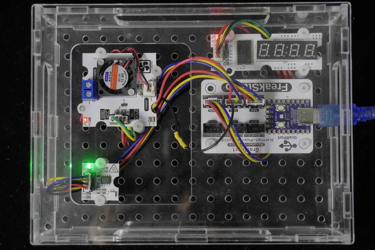
This case requires connecting 3 modules, which can be directly plugged into the standard interfaces of the development board as required:
2.1 Wiring of GUVA-S12SD Ultraviolet Sensor
We connect the GUVA-S12SD ultraviolet sensor module to the AIN0 interface of the development board.
2.2 Wiring of Cooling Fan Module
We connect the cooling fan module to the DIO1 interface of the development board
2.3 Wiring of 4-Digit Nixie Tube Module
We connect the 4-digit digital tube module to the DIO0 interface of the development board.
📌 Wiring Tips
- The GND of all modules
- The fan module requires a 5V power supply; connecting it to 3.3V will result in insufficient speed or failure to rotate.
- The CLK/DIO pins of the digital tube must be connected correctly (Pin10/Pin11), otherwise the values cannot be displayed properly.
3. Program Description
The core of this case lies in the logic chain of "real-time detection → numerical display → threshold judgment → fan start/stop". We will break it down following the order of building block assembly, so even beginners can understand it step by step:
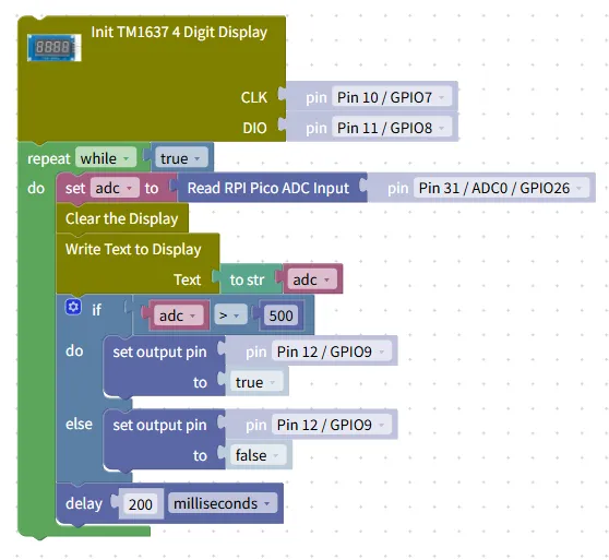
- Hardware Initialization Block (Pre-step, Critical!)
- Digital tube initialization: Use the
Init TM1637 4 Digit Displayblock, set CLK= Pin10/GPIO7 and DIO= Pin11/GPIO8 to activate the digital tube display function; - Fan initialization: Set the DIO1 interface (Pin12/GPIO9) to output mode to prepare for controlling the start and stop of the fan.
- Digital tube initialization: Use the
- Infinite Loop Block (
repeat while true)- Function: Keeps the logic flow of "detection → display → judgment → control" running continuously, and refreshes data every 200 milliseconds;
- Location: All function blocks must be placed inside this loop.
- Data Acquisition Block
- Read UV intensity: Use the
Read RPI Pico ADC Inputblock to read the analog value of the AIN0 interface (Pin31) and store it in theadcvariable; - Logic Description: The analog value range of the ultraviolet sensor is 0-1023, and a larger value indicates stronger ultraviolet intensity.
- Read UV intensity: Use the
- Digital Tube Display Block
- Clear the screen: Use the
Clear the Displayblock to erase the original display on the digital tube, so as to avoid interference from residual values; - Display value: Use the
Write Text to Displayblock to convert theadcvariable into a string and display it on the digital tube; - Effect: The digital tube will refresh the current ultraviolet intensity value in real time, displaying numbers such as "350", "620", etc.
- Clear the screen: Use the
- Threshold judgment block (
ifcondition judgment)- Configuration: Judge
adc > 500(ultraviolet intensity ≥ strong level); - Function: When the ultraviolet rays are too strong, it will trigger the fan to rotate; when the intensity decreases, the fan will stop.
- Configuration: Judge
- Fan control block (
if-elsebranch)- Trigger State (
ifBranch):Set output pin Pin12/GPIO9 to trueto start the cooling fan; - Normal state (
elsebranch):set output pin Pin12/GPIO9 to false, stop the cooling fan; - Logic description: A high level supplies power to the fan to make it rotate; a low level cuts off the power supply, causing the fan to stop.
- Trigger State (
- Debounce Delay Block
- Add
a delay of 200 millisecondsto prevent frequent fan on/off cycles caused by minor fluctuations in sensor readings, making the system more stable.
- Add
Program running effect:
1.3.MP4 168.0 MB
- Initial state: When the UV intensity is low, the digital tube displays the current value (e. g., "280") and the fan does not rotate;
- Trigger condition: When the ultraviolet intensity is ≥ 500, the nixie tube displays values such as "520", and the fan starts to rotate;
- Recovery Status: When the UV intensity drops below 500, the fan will automatically stop, and the digital tube will continuously display the real-time value.
A Beginner's Guide to Avoiding Common Pitfalls
- Does the digital tube not display / display garbled characters?
- Check whether the CLK/DIO pins are connected correctly (Pin10/Pin11), and whether the pin configuration of the initialization building block is consistent with the hardware;
- Make sure the power supply of the digital tube is 3.3V; connecting it to 5V may damage the module.
- Fan not spinning / spinning slowly?
- Check whether the fan is connected to the DIO1 interface (Pin12) and whether the correct high-level trigger is set in the program;
- Confirm that the fan is powered by 5V; 3.3V power supply will result in insufficient rotational speed.
- Sensor value abnormal / not moving?
- Check whether the wiring of the AIN0 interface (Pin31) is loose, and whether the sensor is directly facing an ultraviolet light source (such as sunlight);
- UV sensors are designed for use in lit environments; their readings will approach zero in complete darkness.
✨ Interactive Mini Quiz
- Think about it: If you want to change the threshold for "strong ultraviolet rays" from 500 to 400, which block in the program needs to be modified? (Answer: Just change the pure number block "500" in
if adc > 500to "400") - Try it out: Add a "UV intensity level indicator" to the case — when the value is < 300, display "Weak"; when it is between 300 and 500, display "Medium"; when it is ≥500, display "Strong". Can you make the digital tube show the text prompt?
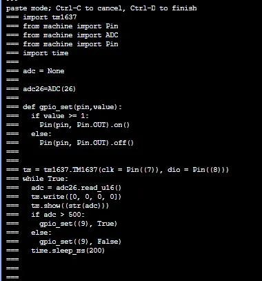
Directly importable building blocks: