
Contents
- 1. Case Introduction
- 1.1 Modules Used
- 1.2 Creative Gameplay
- 1.3 Core Learning Points (Essential for Beginners to Master)
- 2. Wiring Instructions
- 2.1 Wiring of TSP034138 Infrared Receiving Module
- 2.2 Wiring of IR333C Infrared Transmitting Module
- 2.3 Wiring of Passive Buzzer Module
- 2.4 Microphone Module Wiring
- 3. Program Description
Young makers, do you want to make a magical "sound transmission through the air" toy🪄? No wires needed — you can send your voice to a distant place via invisible infrared rays, just like playing with a "whisper transmitter"! Today, we’ll use an infrared module and a microphone to create a small infrared sound-transmission toy that lets your voice "fly"~
1. Case Introduction
1.1 Modules Used
- Core Inputs: TSP034138 infrared receiving module ("infrared ear", which captures infrared signals in the air), microphone module ("sound catcher", which picks up your voice)
- Core Outputs: IR333C infrared transmitting module (the "infrared mouth", which converts sound into infrared signals and transmits them), passive buzzer module (the "sound player", which converts infrared signals into sound for playback)
1.2 Creative Gameplay
This toy can achieve the magical effect of "wireless sound transmission":
- Sound acquisition: Speak into the microphone, and the module will convert the sound into an electrical signal;
- Infrared transmission: The infrared transmission module encodes electrical signals into infrared light and transmits it into the air;
- Infrared Reception: After the infrared receiving module captures the infrared signal, it decodes the signal into the original electrical signal;
- Sound playback: The buzzer module converts electrical signals into sound for output;
- As long as the infrared transmitter and receiver are aligned, your voice can "travel through the air" even from a distance of several meters, just like using a mini walkie-talkie!
1.3 Core Learning Points (Essential for Beginners to Master)
- Learn to transmit and receive infrared signals (understand the principle of "invisible wireless communication");
- Master the acquisition and conversion of analog audio signals (the complete link: microphone → electrical signal → infrared → buzzer);
- Understand signal threshold judgment (determine whether there is sound input based on the microphone value);
- Enable multi-module collaborative operation (the complete process of input → encoding → transmission → decoding → output);
- Master the flexible use of advanced interfaces (temporarily use the I2C interface as a DIO port to drive the buzzer).
2. Wiring Instructions
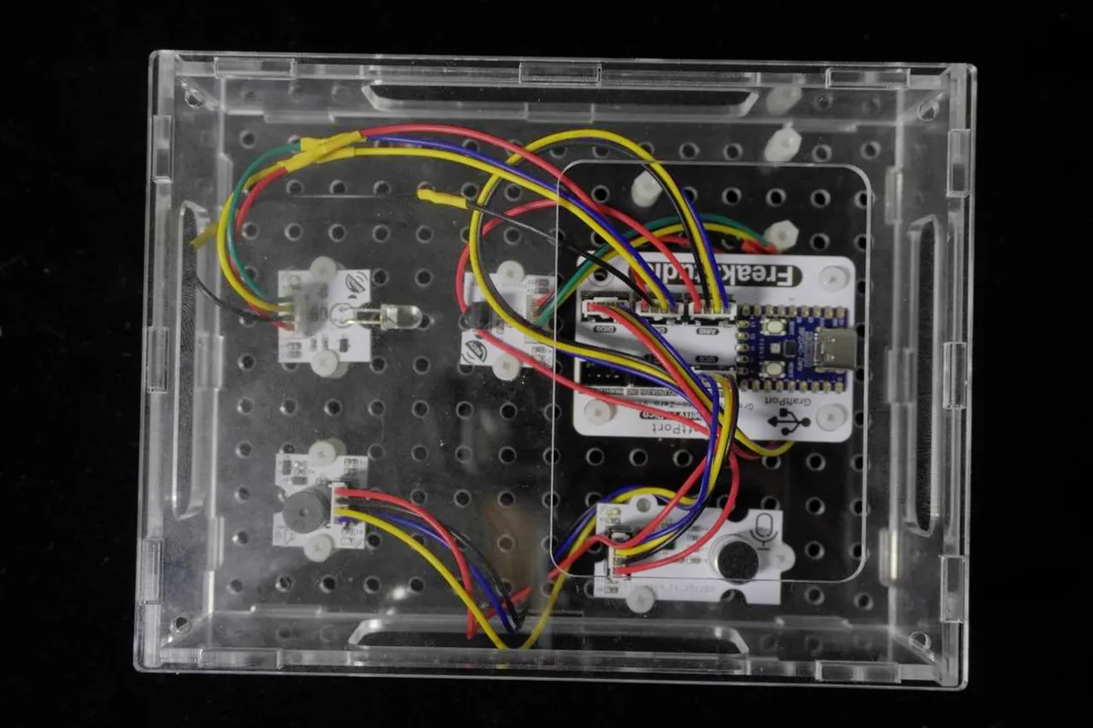
This case requires connecting 4 modules, which can be directly plugged into the standard interfaces of the development board as required.
2.1 Wiring of TSP034138 Infrared Receiving Module
We connect the TSP034138 infrared receiving module to the DIO0 interface of the development board
2.2 Wiring of IR333C Infrared Transmitting Module
We connect the IR333C infrared transmitting module to the DIO1 interface of the development board.
2.3 Wiring of Passive Buzzer Module
We connect the passive buzzer module to the I2C0 interface (temporarily used as a DIO port)
2.4 Microphone Module Wiring
We connect the microphone module to the AIN0 interface of the development board
📌 Wiring Tips
- The GND of all modules
- The infrared transmitting and receiving modules must be placed in alignment (with no obstruction in between), otherwise signal transmission will fail;
- Connecting the buzzer to the I2C0 interface is a flexible application of "using a high-level interface as a low-level one", and it is necessary to ensure that the I2C0 interface is not occupied by other devices.
3. Program Description
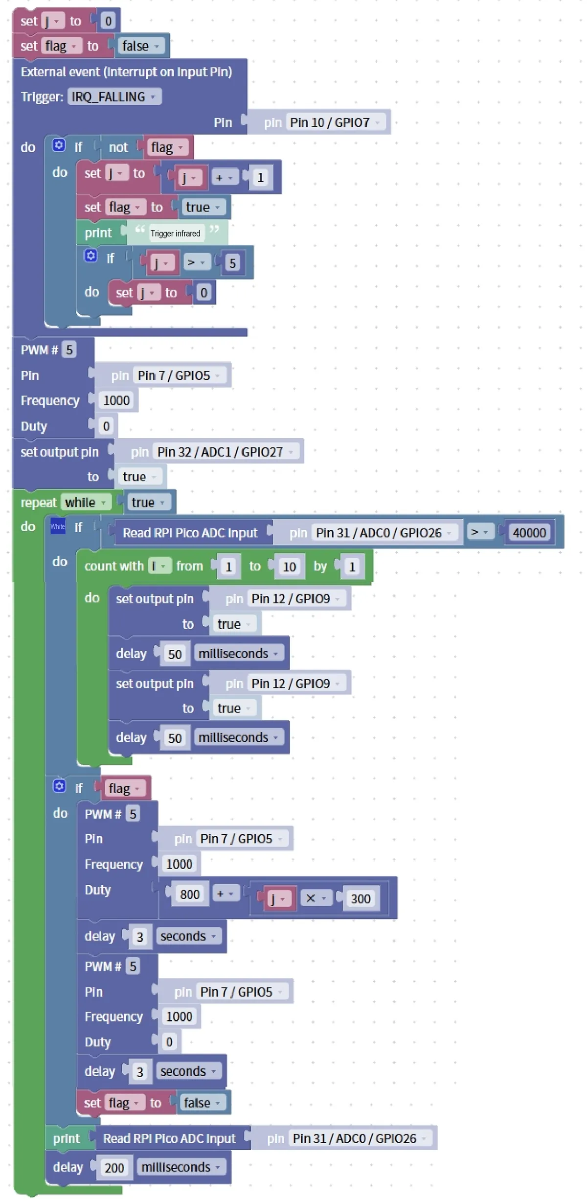
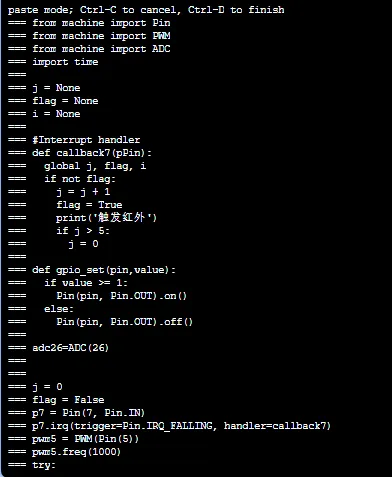
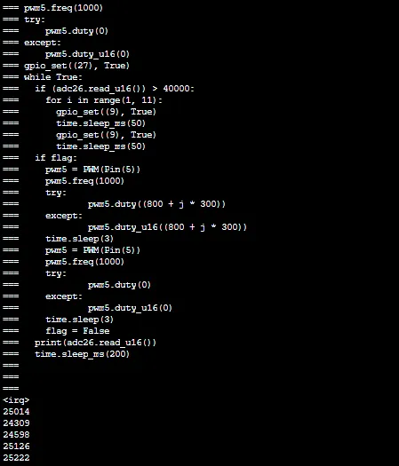
The core of this case lies in the process of "sound collection → infrared transmission → infrared reception → sound playback". We will break it down according to the sequence of building block assembly, so even beginners can follow along step by step:
- Hardware Initialization Block (Pre-step, Critical!)
- Infrared module initialization: Set DIO0 (reception) to input mode and DIO1 (transmission) to output mode;
- Microphone initialization: Set AIN0 to analog input mode for reading sound signals;
- Buzzer Initialization: Set Pin6 of the I2C0 interface to output mode + PWM function to prepare for driving the buzzer to generate sound.
- Infinite Loop Block (
repeat while true)- Function: Continuously collect sound, transmit infrared signals, receive and play audio to realize real-time sound transmission;
- Location: All function blocks must be placed inside this loop.
- Sound Collection and Judgment Block
- Read the volume: Use the
Read RPI Pico ADC Inputblock to read the analog value of the microphone on AIN0, and store it in theadcvariable; - Threshold judgment: Use
if adc > 100to determine whether there is sound input (if the volume exceeds 100, it is judged as "sound present"); - Logic description: The higher the microphone value, the louder the sound, and the threshold can be adjusted according to the ambient noise.
- Read the volume: Use the
- Infrared emission block (within the
ifbranch)- Encoding and Transmission: Convert the analog value from the microphone into a PWM signal, and send it to the infrared transmitting module through the DIO1 pin;
- Logical Description: The infrared module encodes electrical signals into infrared light and transmits it into the air, thus realizing the conversion from "sound to infrared".
- Infrared Receiving and Playing Building Block
- Receive signal: Use the
read digital inputblock to read the infrared received signal from the DIO0 pin; - Buzzer Playback: Convert the received signal into a PWM signal, and drive the buzzer to sound via Pin6 of the I2C0 interface;
- Logic description: The buzzer plays sounds according to the frequency and amplitude of the signal, realizing the restoration from "infrared" to "sound".
- Receive signal: Use the
- Debounce Delay Block
- Add
a delay of 20 millisecondsto prevent frequent triggering caused by ambient noise and ensure more stable sound transmission.
- Add
Program running effect:
- Initial state: When there is no sound, the infrared transmitting module does not work, and the buzzer remains silent;
- Speech Trigger: Speak into the microphone, the infrared transmitting module will light up (emit infrared light), and the buzzer will play your voice synchronously;
- Occlusion Test: Block the infrared transmitter/receiver end with your hand; if the buzzer stops sounding, it indicates that the signal is blocked.
- Distance Test: In an unobstructed environment, the sound transmission distance can reach 2-3 meters, allowing you to experience the fun of "transmitting sound across space".
A Beginner’s Guide to Avoiding Common Pitfalls
- Infrared receiver not picking up signal?
- Check whether the infrared transmitting and receiving modules are aligned, and whether there is any obstruction between them;
- Adjust the sound threshold (e. g., change "100" to "50") to increase the sensitivity.
- Buzzer not sounding / low volume?
- Check whether the buzzer is connected to the I2C0 interface (Pin6), and whether the PWM frequency is in the range of 1000-3000Hz;
- Make sure the buzzer is powered by 5V; 3.3V power supply will result in weak sound.
- Microphone not picking up any sound?
- Check whether the wiring of the AIN0 interface (Pin31) is loose and whether the microphone is close to the sound source;
- Rotate the potentiometer on the microphone module to adjust the gain (turn clockwise to increase the volume).
✨ Interactive Quick Quiz
- Think about it: If you block the light between the infrared transmitting and receiving modules with your hand, can the buzzer still play sound? (Answer: No! The infrared signal is an optical signal, which cannot be transmitted after being blocked, and the buzzer will be muted)
- Try it out: Add a "volume adjustment" function to the example — use a potentiometer to adjust the microphone's sensitivity for clearer sound transmission. Can you add the potentiometer block to it?
Directly importable building blocks: