
Contents
Young makers, would you like to make a pocket detective 🔍 that can measure your body's oxygen level?
Simply place your finger gently on the sensor, and it will calculate the oxygen level in your blood, and vibrate to alert you when the reading is too low, just like your personal health assistant! Today, we will use the MAX30100 sensor, a digital tube display and a vibration motor to build a simple health monitor that can "read your body's signals".
1. Case Introduction
1.1 Modules Used
- Core Input: MAX30100 Heart Rate and Blood Oxygen Sensor (dubbed the "body oxygen detective", which captures red/infrared light signals from the finger to estimate blood oxygen levels)
- Core Outputs: A 4-digit digital tube based on TM1637 (the "digital display screen" that clearly shows blood oxygen readings), and a vibration motor module (the "vibration reminder" that triggers a vibration alert when blood oxygen levels are low)
1.2 Creative Gameplay
This monitor can deliver the practical functions of "fingertip blood oxygen measurement + real-time display + abnormality alert":
- Fingertip Sensing: Gently place your finger on the sensing area of the MAX30100 sensor, and the sensor will capture the signal of light passing through your finger;
- Numerical calculation: Estimate your blood oxygen saturation based on the signal ratio of red light to infrared light;
- Digital display: The 4-digit nixie tube will display the blood oxygen value in real time (for example, when the blood oxygen is at a normal level of 98%, it will show "0098");
- Abnormality Alert: If the blood oxygen level is ≤ 90 (the critical threshold for human hypoxemia), the vibration motor will activate immediately to remind you, "Your body is low on oxygen!"
1.3 Core Learning Points (Essential for Beginners to Master)
- Learn the initialization and data reading of I2C sensors (understand the conversion logic of "light signal → blood oxygen value");
- Master numerical operations and range constraints (use simple formulas to estimate blood oxygen and ensure the results conform to the actual physiological conditions of the human body);
- Learn the digital display and format zero-padding of 4-digit nixie tubes (to make the numerical display more standardized);
- Implement condition-triggered vibration alerts (control peripheral actions via judgment logic);
- Understand the collaborative work of multiple modules (the complete process of input → operation → output → reminder).
2. Wiring Instructions
This case requires connecting 3 modules, which can be directly plugged into the standard interfaces of the development board as required:
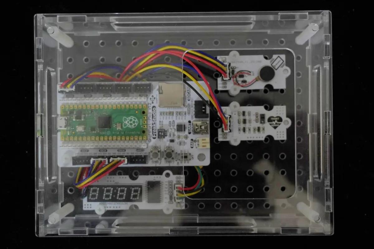
2.1 Wiring of MAX30100 Heart Rate and Blood Oxygen Sensor
Connect the module to the I2C0 interface on the development board.
2.2 Wiring of 4-digit Nixie Tube Module
Connect the module to the DIO2 interface on the development board
2.3 Wiring of Vibration Motor Module
Connect the module to the DIO0 interface on the development board
📌 Wiring Tips
- The GND of all modules must share a common ground with the development board; otherwise, the signals will jump erratically and the modules will fail to work.
- Gently place your finger against the sensing area of the MAX30100 (do not press hard), otherwise it will interfere with optical signal acquisition;
- The CLK/DIO pins of the digital tube must be completely consistent with the configuration of the initialization block, otherwise numbers cannot be displayed properly.
3. Program Description
The core of this case lies in the workflow of "signal acquisition → numerical operation → display reminder". We break it down in the order of building block assembly, so even beginners can follow along step by step:
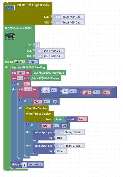
- Hardware Initialization Block (Pre-step, Critical!)
- MAX30100 Initialization: Configure the SCL/SDA pins of the I2C0 interface to initiate sensor communication;
- Digital tube initialization: Configure the CLK/DIO pins and set the digital tube to display mode;
- Vibration motor initialization: Set the DIO0 pin to output mode to prepare for controlling the motor vibration.
- Infinite Loop Block (
repeat while true)- Function: Continuously collect finger signals, calculate blood oxygen values, update displays and send reminders to realize real-time monitoring;
- Location: All function blocks must be placed inside this loop.
- Read original value block
- Use
Update MAX30100 Readingto refresh the sensor data; - Use
Get MAX30100 Red ValueandGet MAX30100 IR Valueto read the raw values of red light (Red) and infrared light (IR) respectively; - Logic description: The IR value cannot be 0 (otherwise an error will occur during division), and the program will automatically skip invalid data where IR = 0.
- Use
- Blood Oxygen Value Calculation Block
- Calculate according to the formula:
Blood oxygen value = 100 -(25 *(Raw Red value / Raw IR value)); - Range Limitation: Use a judgment block to ensure the blood oxygen value stays between 90 and 100 (if the value is lower than 90, set it to 90; if higher than 100, set it to 100), so as to guarantee the result conforms to the actual blood oxygen range of the human body.
- Calculate according to the formula:
- Digital Tube Display Block
- Use
Clear the Displayto clear the previous display content; - Use
Write Text to Displayto pad the blood oxygen value with leading zeros to a 4-digit format (e. g. 98 → "0098") and display it on the digital tube; - Logic description: The zero-padding format makes the numerical display clearer and prevents digit confusion caused by "98" being displayed as "98".
- Use
- Abnormal Vibration Alert Block
- Use
if blood oxygen value ≤ 90to determine whether to trigger an alert; - If the condition is true: use
set output pinto make the vibration motor vibrate continuously for 0.5 seconds; - If the condition is not met: use
set output pinto turn off the vibration motor; - Logic explanation: 90 is the critical value for low blood oxygen in the human body, and the vibration reminder allows you to detect abnormalities in time.
- Use
- Debounce Delay Block
- Add
a 1-second delayto make data updates more stable and prevent value fluctuations caused by frequent operations.
- Add
Program running effect:
C2201.MP4 220.0 MB
- Initial state: When no finger touches the sensor, the digital tube displays "0000" and the vibration motor does not operate;
- Normal monitoring: After the finger is lightly placed on the sensor, the digital tube displays the real-time blood oxygen value (e. g. "0098"), and the motor does not vibrate;
- Abnormality Alert: If the blood oxygen value is ≤90 (e. g., simulating a hypoxemia state), the motor will vibrate immediately, and the digital tube will display "0090";
- Release Test: After the finger is removed from the sensor, the value will reset to "0000" and the vibration will stop.
A Beginner’s Guide to Avoiding Common Pitfalls
- Does the digital tube not display / display garbled characters?
- Check whether the digital tube is connected to the DIO2 interface and whether the wiring is loose;
- Confirm that the configuration of the digital tube initialization block is correct, and check whether the zero-padding format is set to 4 digits.
- Sensor fails to read data / IR value is 0?
- Check whether the MAX30100 is connected to the IIC0 interface, and whether the I2C pins (SDA/SCL) are correctly matched;
- Make sure your finger completely covers the sensor's sensing area, and avoid direct strong light hitting the sensor.
- Vibration motor not vibrating / vibrating continuously?
- Check whether the motor is connected to the DIO0 interface and whether the GND is common grounded with the development board;
- Check whether the conditional judgment block "if spo2 ≤ 90" is misassembled and whether the 500-millisecond delay is added correctly.
✨ Interactive Mini Quiz
- Think about it: Why do we need to first check whether "IR value ≠ 0" before calculating the blood oxygen value? (Answer: Because the formula involves division, and the divisor cannot be 0, otherwise the program will report an error and stop running!)
- Try it: Add a "normal blood oxygen reminder" function to the sample project — when the blood oxygen value is ≥95, make the vibration motor vibrate gently for 0.2 seconds to remind "blood oxygen is normal". Can you add the delay and conditional judgment blocks?
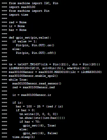
Directly importable building blocks: