
Contents
Young makers, are you still shaking the dice manually when playing dice games?
Today we are going to make an extremely cool motion-sensing fun dice roller 🎲! Simply give the development board a gentle shake, and it will simulate the effect of rolling dice: the digital tube will scroll through numbers 1 to 6, and the vibration motor will give you different feedback, just like you are actually holding a vibrating dice in your hand – it's super fun and amazing!
1. Case Introduction
1.1 Modules Used
- Core Input: MPU6050 6-axis gyroscope module ("shake detector", which senses your shaking movements and changes in acceleration)
- Core Outputs: 4-digit seven-segment display module ("dice display", which dynamically scrolls and displays the dice roll value), vibration motor module ("vibration feedback device", which provides different vibration prompts according to the dice roll value)
1.2 Creative Gameplay
This motion-sensing dice frees you from the limitations of manual dice rolling, and the gameplay is incredibly fun:
- Shake Trigger: Gently shake the development board. After the MPU6050 detects the acceleration change, the digital tube will quickly scroll and display a random number from 1 to 9999 (simulating the dynamic effect of shaking dice), and the vibration motor will vibrate at high frequency at the same time;
- Stop value: After shaking stops, the digital tube will fixedly display a random dice number between 1 and 6;
- Haptic feedback: Different vibration patterns are triggered based on the final score:
- 1 o'clock: 3 short tremors
- 2-5 o'clock: 1 short tremor
- At 6:00: One long tremor
- Repeated Interaction: Shake again to re-trigger the dice-rolling process, so you can play endlessly without getting bored!
1.3 Core Learning Points (Essential for Beginners to Master)
- Learn to read the data of a 6-axis gyroscope (obtain changes in acceleration/angular acceleration to determine shaking motions);
- Master the shake detection threshold logic (which uses the absolute values of three-axis data to determine whether a shake is triggered);
- Understand random number generation and dynamic display (simulate the dice rolling effect, and finally lock in a number between 1 and 6);
- Implement multi-peripheral linkage feedback (synchronous interaction of digital tube display + vibration motor);
- Proficient in using loop counting and delay control (to achieve vibration rhythms with different beat counts).
2. Wiring Instructions
This case requires connecting 3 modules, which can be directly plugged into the standard interfaces of the development board as required:
2.1 Wiring of MPU6050 6-axis Gyroscope
We connect the MPU6050 six-axis gyroscope module to the I2C0 interface of the development board.
2.2 Wiring of 4-digit Nixie Tube Module
We connect the 4-digit digital tube module to the DIO0 interface of the development board.
2.3 Wiring of Vibration Motor Module
We connect the vibration motor module to the DIO1 interface on the development board.
📌 Wiring Tips
- The GND of all modules
- The MPU6050 requires a warm-up period of 1 to 2 minutes; otherwise, the initial attitude data will be unstable, leading to inaccurate shake detection.
3. Program Description
The core of this case lies in the workflow of "shake detection → dynamic rolling → point locking → vibration feedback". We break it down in the order of building block assembly, so even beginners can follow along step by step:
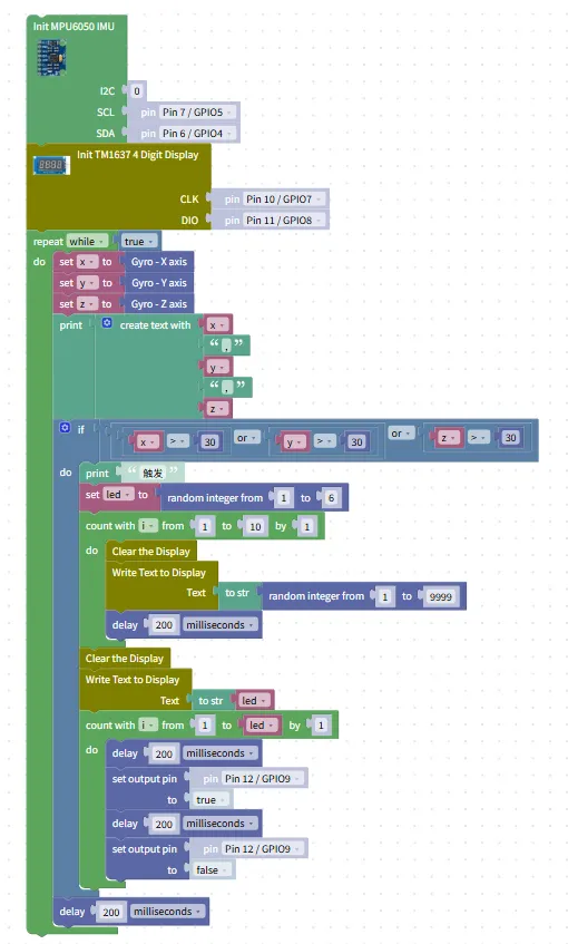
- Hardware Initialization Block (Pre-step, Critical!)
- MPU6050 Initialization: Configure the I2C0 interface (SDA = Pin6, SCL = Pin7) to activate the 6-axis attitude detection function;
- Digital tube initialization: use the
Init TM1637 4 Digit Displayblock, set CLK= Pin10/GPIO7, DIO= Pin11/GPIO8; - Vibration motor initialization: Set the DIO1 interface (Pin12/GPIO9) to output mode to prepare for controlling the motor vibration.
- Infinite Loop Block (
repeat while true)- Function: Continuously detect shaking movements to realize the circular interaction of "shake → stop → feedback";
- Location: All function blocks must be placed inside this loop.
- Attitude Data Reading Block
- Read gyroscope data /
Gyro-X Axis/Gyro-Y Axis/Gyro-Z Axisblocks to obtain the triaxial angular acceleration values and store them in thex/y/zvariables; - Logic description: When shaking, the triaxial angular acceleration will suddenly increase, and the dice rolling will be triggered once it exceeds the set threshold.
- Read gyroscope data /
- Shake detection block (
ifmulti-condition judgment)- Configuration: Judgment
absolute (x) > 30 OR absolute (y) > 30 OR absolute (z) > 30(if the angular acceleration in any of the three axes exceeds 30, it is determined as shaking); - Function: After a shaking motion is detected, the "dice rolling" process will be triggered.
- Configuration: Judgment
- Dice rolling and display block (within the
ifbranch)- Trigger prompt:
print "Trigger", which displays a shake trigger signal in the terminal; - Generate a random dice roll value: use
random integer from 1 to 6to generate the final dice roll result and store it in theledvariable; - Dynamic scrolling display: Use the
count with i from 1 to 10loop to generate a random number between 1 and 9999 each time and display it on the nixie tube, simulating the dynamic effect of dice rolling; - Lock display points: After scrolling ends, clear the digital tube and display the final points
led.
- Trigger prompt:
- Vibration Feedback Building Blocks (Vibration Corresponding to the Number of Points)
- 1 point of feedback: if
led= 1, use thecount with i from 1 to 3loop to control the motor to vibrate briefly 3 times (each vibration lasts 200ms with a 200ms interval between vibrations); - 2-5 point feedback: if
the ledis 2-5, control the motor to vibrate briefly once; - 6-point feedback: If
led= 6, control the motor to vibrate continuously once (with a longer vibration duration); - Logic description: By adjusting the number of cycles and the delay time, differentiated vibration prompts are realized to make the point feedback more intuitive.
- 1 point of feedback: if
- Debounce Delay Block
- Add
a delay of 200 millisecondsto prevent false triggers caused by minor jitter and make shake detection more accurate.
- Add
Program running effect:
Motion-sensing fun dice roll.mp4 59.7 MB
- Initial state: The digital tube has no display and the motor does not vibrate;
- Shake Trigger: Scroll to display a random number between 1 and 9999, and the motor vibrates at high frequency to simulate the shaking of dice;
- Stop shaking: The digital tube fixedly displays the number of dots from 1 to 6, and the motor triggers corresponding vibration according to the number of dots (e. g., 1 dot triggers 3 short vibrations, 6 dots triggers a long vibration);
- Shake again: Re-enter the rolling process, and the interaction can be repeated infinitely.
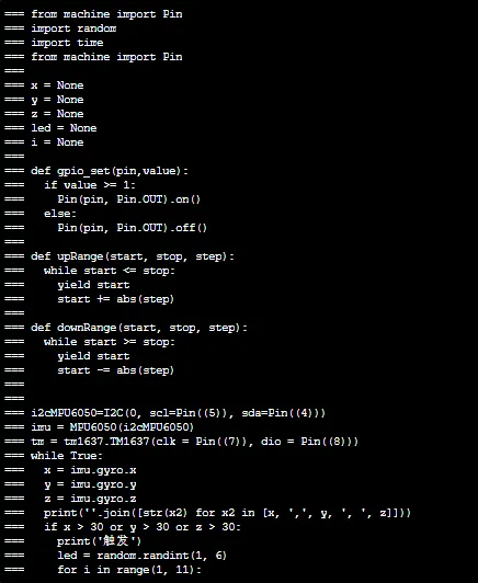
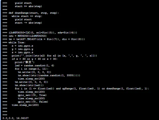
A Beginner's Guide to Avoiding Common Pitfalls
- Is the shake detection insensitive / triggered falsely?
- Adjust the shake threshold: to increase the sensitivity, change the value "30" in the judgment condition to a smaller number (e. g. 20); to decrease the sensitivity, change it to a larger number (e. g. 40);
- Ensure that the MPU6050 is firmly fixed to avoid data jitter caused by looseness.
- Garbled display or non-scrolling on the digital tube?
- Check whether the CLK/DIO pins are connected correctly (Pin10/Pin11), and whether the pin configuration of the initialization block is consistent with the hardware;
- Make sure the power supply of the digital tube is 3.3V; connecting it to 5V may damage the module.
- Vibration motor not vibrating / weak vibration?
- Check whether the motor is connected to the DIO1 interface (Pin12) and whether the correct high-level trigger is set in the program;
- Confirm that the motor is powered by 5V; 3.3V power supply will result in insufficient vibration intensity.
✨ Interactive Mini Quiz
- Think about it: If you want to make the shake detection more sensitive, which block in the program needs to be modified? (Answer: Modify the threshold "30" in the shake detection condition, for example, change it to "20", so that a smaller acceleration can trigger the shake)
- Try it out: Add a "sound effect feedback" to the project: when shaken, the buzzer makes a "clattering" sound, and after shaking stops, it plays different tones based on the rolled points. Can you add the buzzer block to the code?
Directly importable building blocks: