
Contents
Young makers, have you ever thought about installing a "little security guard against theft" for your books and stationery?
Today we will use the SW-18010P vibration sensor to make a mini vibration alarm guardian 🔒 — whenever someone secretly moves your belongings, it will immediately trigger a buzzer alarm and light up the red LED. Just like a loyal guardian, it ensures your items will never be taken away without a trace again!
1. Case Introduction
1.1 Modules Used
- Core Inputs: SW-18010P vibration sensor (detects vibration signals generated when an item is moved);
- Core Outputs: Passive buzzer module (for emitting alarm tones), piranha LED module (red light visual warning).
1.2 Creative Gameplay
Affix the vibration sensor to books, pencil cases or valuables with double-sided adhesive tape, then activate the "Guard Mode":
- Normal state: When there is no vibration, the buzzer stays silent and the red light turns off, so it won't disturb your study;
- Alarm Trigger: When the item is moved (vibration detected), the buzzer will beep continuously for 3 seconds while the red light turns on simultaneously for 3 seconds, alerting you that "Someone has touched my stuff!";
- Automatic reset: The system will automatically restore mute mode and turn off the red light 3 seconds after the alarm is triggered, then continue to enter the "monitoring state".
1.3 Core Learning Points (Essential for Beginners to Master)
- Learn the trigger logic of the vibration sensor (outputs a low level when vibration is detected, and uses a "not" operation to determine trigger alarm);
- Master the security scenario logic of " trigger alarm + delayed reset ";
- Understand the application of the " NOT " logic in sensor detection (for handling sensors triggered by low level);
- Implement the linked alarm function of buzzer plus LED (dual reminder of sound and visual);
- Develop a programming mindset for security scenarios (converting "object movement" into "alarm signals").
2. Wiring Instructions
This case requires connecting 3 modules according to the standard interfaces of the development board, and you can directly plug them into the corresponding interfaces.
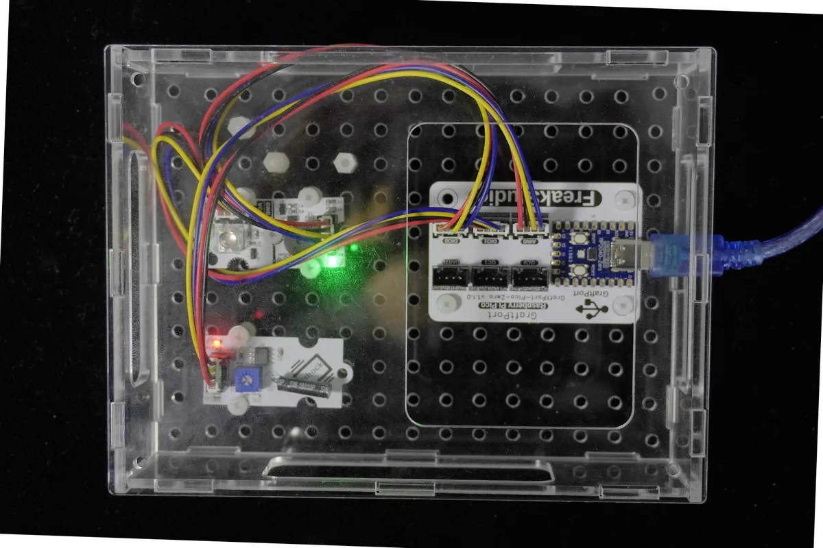
2.1 Wiring of SW-18010P Vibration Sensor
We connect the SW-18010P vibration sensor module to the AIN0 interface of the development board, and only use the DIN pin (the second pin of the module's interface) for vibration detection.
2.2 Wiring of Passive Buzzer Module
We connect the passive buzzer module to the DIO0 interface on the development board.
2.3 Wiring of Piranha LED Light Module
We connect the Piranha LED light module to the DIO1 interface of the development board.
📌 Wiring Tips
- Sensitivity Adjustment: The potentiometer on the vibration sensor allows adjustment of the detection sensitivity — rotating clockwise increases sensitivity (triggers even with minor vibration); rotating counterclockwise decreases sensitivity (requires stronger vibration to trigger).
- Fixed sensor: When attaching it to an item, secure it with double-sided adhesive or hot melt glue to avoid looseness that may lead to inaccurate detection.
- Notes on Shared Pins: If the buzzer and LED share the DIO0 pin, take care not to let the current be too high (it is recommended to connect them to separate pins, for example, connect the buzzer to DIO0 and the LED to DIO1 for higher stability).
- The GND of all modules
3. Program Description
The core of this case lies in the process of "continuous vibration detection → alarm triggering → delayed reset". We break it down in the order of building block assembly, so even beginners can follow along step by step:
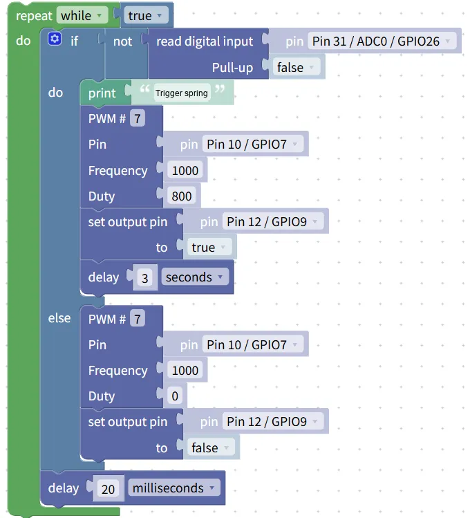
- Hardware Initialization Block (Pre-step, Critical!)
- Vibration sensor initialization: Set the AIN0 interface to "input mode + pull-down resistor (Pull-up= false)" to ensure that it outputs a high level when there is no vibration and a low level when triggered.
- Buzzer / LED Initialization: Set the DIO0 interface to "output mode + PWM function" to prepare for controlling the buzzer to sound and the LED to turn on and off.
- Infinite Loop Block (
repeat while true)- Function: Enables the system to continuously detect vibration signals, standing guard around the clock to protect items.
- Location: All detection and alarm logic are placed inside this loop.
- Vibration detection judgment block (
if not read digital input)- Configuration: Detect the level of the AIN0 interface,
notmeans "when the sensor outputs a low level (i. e., vibration is detected)", it is judged as "true". - Logic: When the SW-18010P detects vibration, it outputs a low level;
not low level = true, triggering an alarm; when no vibration is detected, it outputs a high level,not high level = false, maintaining the normal state.
- Configuration: Detect the level of the AIN0 interface,
- Alarm trigger block (
ifwithin the branch)- Terminal prompt:
print "Trigger spring"(can be modified to "Vibration detected! Alarm triggered" for better intuitiveness); - Buzzer Ring:
PWM #7block sets the frequency to 1000Hz and the duty cycle to 800, making the buzzer continuously emit a loud prompt tone; - Red light turns on:
set output pin DIO0 to true, to turn on the red LED; - Delay Reset:
delay 3 seconds, which enables the alarm to automatically resume after lasting for 3 seconds.
- Terminal prompt:
- Normal state block (
elsebranch)- Buzzer Mute:
PWM #7The block sets the duty cycle to 0 to stop sound output; - Red light turns off:
set output pin DIO0 to false, turn off the LED; - Debounce Delay:
delay 20 milliseconds, which prevents frequent detection caused by minor jitter and makes the system more stable.
- Buzzer Mute:
Program running effect:
C2184.MP4 60.0 MB
- Initial state (no vibration): The buzzer is silent, the red light is off, and there is no prompt on the terminal;
- Vibration triggered (item moved): The buzzer sounds continuously immediately, the red light turns on synchronously, and the terminal prints "spring triggered";
- Alarm reset: The buzzer will stop automatically after 3 seconds, the red indicator light will turn off, and the system will return to the "monitoring status" to continue detection.
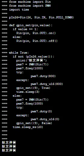
Directly importable building blocks:
Vibration alarm little guard.xml 5 KB
A Beginner's Guide to Avoiding Common Pitfalls
- Is the vibration detection insensitive / false triggers occur frequently?
- Adjust the potentiometer on the sensor: if the sensitivity is too high (false triggering), turn it counterclockwise to decrease the sensitivity; if the sensitivity is too low (failure to detect), turn it clockwise to increase the sensitivity.
- Ensure that the sensor is firmly attached to the object to avoid insufficient vibration transmission caused by loosening.
- Buzzer does not sound / LED does not light up?
- Check whether the pins are connected correctly (DIO0) and whether the PWM frequency is in the range of 1000-3000Hz (the buzzer produces the clearest sound within this range).
- If shared pins result in insufficient current, it is recommended to connect the buzzer and the LED to separate DIO ports (e. g., connect the buzzer to DIO0 and the LED to DIO1).
- Is it impossible to reset automatically after an alarm is triggered?
- Check
delay 3 secondswhether the block is correctly added to the alarm branch, and ensure that the reset logic is executed after the alarm lasts for 3 seconds.
- Check
✨ Interactive Mini Quiz
- Think about it: Why do we use "
not read digital input" to detect vibration in the program, instead of directly using "read digital input"? (Answer: Because the SW-18010P outputs a low level when it detects vibration, and only whennot low level = truecan the alarm be triggered; if you directly useread digital input, it will be judged asfalseat low level, which will not trigger the alarm instead) - Try it out: add an "alarm count recording" function to the case — use the variable
countto record the number of triggers. After each alarm, print "Alarm has been triggered X times". Can you add a variable increment block in the alarm branch?