
Contents
Young creators, do you remember that when playing motion-sensing games, you only need to shake the controller to control the character's movement?
Today, we will use the MPU6050 six-axis gyroscope to create a "somatosensory-controlled small LED light array" ✨! As long as you tilt the development board in different directions while holding it, the corresponding LEDs will light up automatically, which is super cool just like "directing" the lights to dance with your body!
1. Case Introduction
1.1 Modules Used
- Core Input: MPU6050 6-axis gyroscope module (senses the tilt angle and orientation of the development board);
- Core Output: 4 piranha LED modules (forming a 2×2 small LED array that turns on and off according to the posture).
1.2 Creative Gameplay
We set a "motion-sensing rule" for the light array: when you tilt the handheld development board, the LEDs will move in sync accordingly.
- Tilt forward → the upper row (top left + top right) LEDs turn on;
- Tilt backward → the lower row (bottom left + bottom right) LEDs light up;
- Tilt left → LEDs in the left column (top left + bottom left) light up;
- Tilt right → LEDs in the right column (top-right + bottom-right) light up;
- Place horizontally → All LEDs turn off (expandable).
1.3 Core Learning Points (Essential for Beginners to Master)
- Learn to read the attitude data of the 6-axis gyroscope (obtain the tilt angles of the X/Y axes);
- Understand the tilt judgment logic for absolute value comparison (to determine which direction has a more pronounced tilt);
- Master the assignment and usage of state variables (using the
ledvariable to record the current tilt direction); - Implement coordinated control of multiple LEDs (turn on/off different combinations of LEDs according to the posture);
- Develop a programming mindset for somatosensory interaction (translating "physical movements" into "code logic").
2. Wiring Instructions
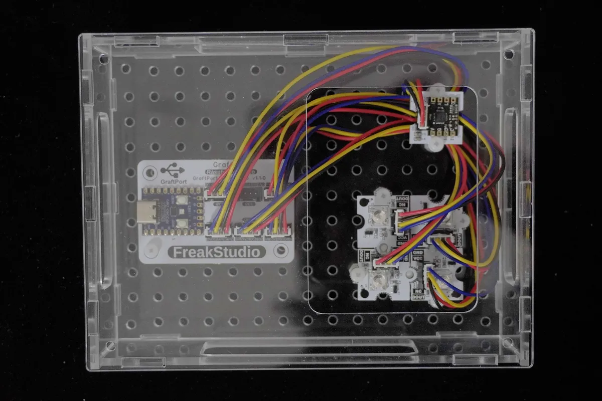
This case requires connecting 2 modules. Just plug them directly into the standard interfaces of the development board, and there is no need to check the pins one by one.
2.1 Wiring of MPU6050 6-axis Gyroscope
We connect the MPU6050 six-axis gyroscope module to the I2C0 interface of the development board.
2.2 Piranha LED Array Wiring
We connect the 4 Piranha LED light modules according to the following correspondence:
- Top-left LED → Development Board DIO0 Interface
- Upper-right LED → Development Board DIO1 Interface
- Bottom-left LED → Development Board AIN0 Interface
- Bottom-right LED → Development Board UART0 Interface
📌 Wiring Tips
- Basic Wiring Requirements:
- The GND of all LED modules must be connected to the common ground of the development board; otherwise, the LEDs will either "flash briefly then turn off" or fail to light up entirely.
- The MPU6050 needs to warm up for 1-2 minutes before use; otherwise, the initial attitude data will be unstable.
- Important Wiring Knowledge (Essential for Primary and Secondary School Students):
- ✅ Why can an LED (digital output module) be connected to the AIN0/UART0 interface? The AIN0 and UART0 interfaces on the development board are essentially "multi-function general-purpose pins", just like the compartments of a schoolbag — even though they are marked for "notebooks" and "pens", you can totally tuck an eraser in there temporarily. An LED only needs a simple "high level on / low level off" signal, so it can work properly when connected to any of these interfaces.
- ❌ Why can't the MPU6050 (I2C module) be connected to a regular DIO port? The MPU6050 needs to transmit "clock-synchronized posture data" via the I2C protocol, which is similar to transferring files with a dedicated data cable. Regular DIO ports do not have clock synchronization functionality, so connecting the MPU6050 to one is like connecting a printer with a regular USB cable — the core required feature is missing, making data transmission completely impossible.
3. Program Description
The core of this case is "read the posture → judge the direction → assign the state → control the LED". We will break it down according to the sequence of building block assembly, so even beginners can understand it step by step:
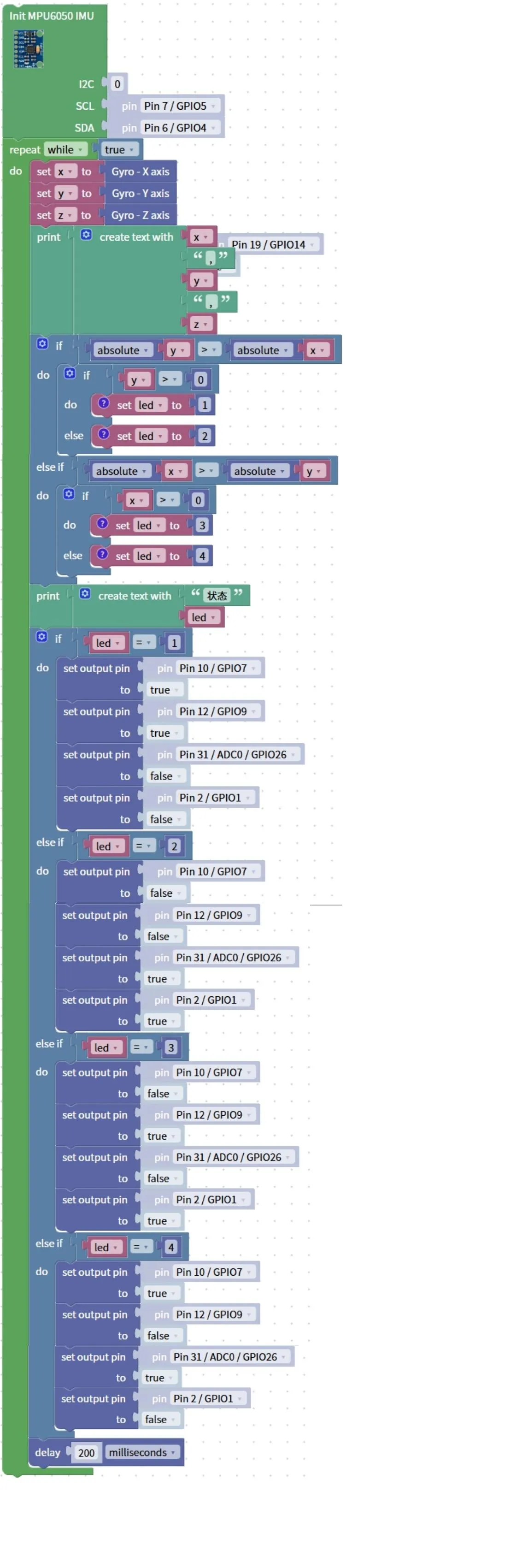
- Hardware Initialization Block (Pre-step, Critical!)
- MPU6050 Initialization: Configure the I2C0 interface (SDA = Pin6, SCL = Pin7) to activate the attitude detection function of the six-axis sensor;
- LED initialization: Set the pins corresponding to the 4 LEDs (DIO0/DIO1/AIN0/UART0) to "output mode" to prepare for controlling their on/off status.
- Global state variable
- Add
an ledvariable with an initial value of0(indicating the "no tilt" state); - Function: Record the current tilt direction with numbers 1-4 (1 = forward, 2 = backward, 3 = right, 4 = left) to make the code logic clearer.
- Add
- Infinite Loop Block (
repeat while true)- Function: This enables the system to continuously read posture data and update the status of the LEDs, so that the LED array responds in real time whenever the handheld development board is tilted.
- Location: All function blocks must be placed inside this loop.
- Attitude Data Reading Block
- Read gyro data: Use the
Gyro-X AxisandGyro-Y Axisblocks to obtain the tilt angle values of the X/Y axes; - Store variables: Store the X-axis data into the
xvariable and the Y-axis data into theyvariable to facilitate subsequent judgment.
- Read gyro data: Use the
- Tilt direction judgment block (nested
if-elselogic)- Step 1: Determine forward/backward or left/right tilt Use
abs (y) > abs (x)to judge: if the absolute value of the Y-axis is larger → it is forward/backward tilt; if the absolute value of the X-axis is larger → it is left/right tilt. - Step 2: Determine the specific direction
- When tilting forward or backward:
y > 0→ tilt forward (led= 1);y < 0→ tilt backward (led= 2); - When tilting left or right:
x > 0→ tilt to the right (led= 3);x < 0→ tilt to the left (led= 4).
- When tilting forward or backward:
- Step 1: Determine forward/backward or left/right tilt Use
- LED Control Block (Multi-Conditional Branching)
Based on the value of the led variable, control the on/off state of the corresponding LED:
led= 1(Forward): The top-left (DIO0) and top-right (DIO1) LEDs are on, while the bottom-left (AIN0) and bottom-right (UART0) LEDs are off;led= 2(backward): The LEDs at the lower left (AIN0) and lower right (UART0) are on, while the LEDs at the upper left (DIO0) and upper right (DIO1) are off;led= 3(right): The LEDs at the upper right (DIO1) and lower right (UART0) are on, while the LEDs at the upper left (DIO0) and lower left (AIN0) are off;led= 4(left): The upper left (DIO0) + lower left (AIN0) LEDs are on, while the upper right (DIO1) + lower right (UART0) LEDs are off.
- Debounce Delay Block
- Add
a delay of 200 millisecondsto prevent frequent LED switching caused by slight hand jitter, making the status of the LED array more stable.
- Add
Program running effect:
C2180.MP4 132.0 MB
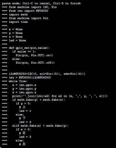
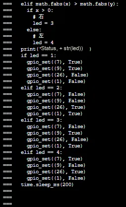
- Initial state: When the development board is placed horizontally, all LEDs are off, and the terminal prints "Status: 0";
- Tilt forward: The upper row of LEDs lights up, and the terminal prints "Status: 1";
- Tilt backward: The lower row of LEDs lights up, and the terminal prints "Status: 2";
- Tilt left / right: The LED of the corresponding column lights up, and the terminal prints "Status: 3" or "Status: 4";
- The greater the tilt angle, the more obvious the on/off response of the LED will be. No buttons are required throughout the process, and it is completely controlled by somatosensory interaction!
Directly importable building blocks:
Motion-controlled light array.xml 36 KB
A Beginner's Guide to Avoiding Common Pitfalls
- MPU6050 data jittering / inaccurate tilt detection?
- Check whether the SDA/SCL pins of the I2C0 interface are securely connected, and whether the module has been preheated for 1-2 minutes;
- You can appropriately increase the "difference threshold" of the judgment condition (for example, change
absolute (y) > absolute (x)toabsolute (y) > absolute (x) + 5) to reduce false positives caused by slight jitter.
- LED not lighting up / lighting up in the wrong position?
- Check whether the LED pins correspond to the configuration in the program (e. g., whether the top-left LED is connected to DIO0);
- Make sure that the GND pins of all LEDs are connected to the common ground of the development board; insufficient power supply will cause the LEDs to dim or fail to light up.
- LED not switching sensitively when tilted?
- Set the
delaytime from 200ms to 100ms to improve the response speed; - When holding the development board, keep it as steady as possible and avoid tilting it in multiple directions at the same time (for example, tilting it forward and to the left simultaneously).
- Set the
✨ Interactive Mini Quiz
- Think about it: if you change the "absolute value comparison" in the judgment condition to a direct comparison
y > x, what problems will arise? (Answer: When both the X and Y axes are negative, the tilt direction will be misjudged. For example, when tilting backward + leftward,y > xholds true but the actual tilt direction is backward; absolute value comparison avoids the interference of positive and negative signs, making it possible to judge the tilt amplitude more accurately) - Try it out: Add a logic of "all LEDs turn off when placed horizontally" to the example. Can you add one at the end of the
if-elsestructureelsebranch to implement it?