
Contents
Young makers, we have already learned how to use individual sensors and peripherals before, and today we are going to take on an extremely practical comprehensive project — the Classroom Environment Monitoring and Comfort Reminder System! Just like a little "environment steward" in the classroom, it can monitor temperature, humidity and light in real time, and once the data goes beyond the "comfort zone", it will use a buzzer and LED to remind everyone, making our classroom a comfortable place to stay forever~
1. Case Introduction
Modules used:
- Core Inputs: DHT11 temperature and humidity sensor (for temperature/humidity measurement), GL5516 light intensity sensor (for light brightness measurement);
- Core Outputs: SSD1306 OLED display (real-time display of environmental data), passive buzzer module (abnormal alarm), and piranha LED light module (visual reminder).
Creative Gameplay:
The system continuously monitors the environmental data of the classroom and displays it in real time on the OLED screen; we have preset a "comfort zone":
- Temperature: 20~28℃
- Humidity: 40%~60%
- Light Intensity: ≥50. As long as any one of the readings falls outside the specified range, the buzzer will beep softly and the Piranha LED will flash to alert everyone, "The environment is not comfortable!"
Core Learning Points (Essential for Beginners to Master)
- Learn multi-sensor collaborative acquisition (simultaneously read temperature, humidity and light intensity data);
- Master OLED screen data visualization (converting numerical data into intuitive text display);
- Understand the threshold judgment logic (using the conditional judgment "whether the data is within the comfort zone");
- Implement multi-peripheral linkage reminder (buzzer and LED trigger alarm simultaneously);
- Proficient in using loop monitoring + data refresh (to keep the system running continuously and update in real time).
2. Wiring Instructions
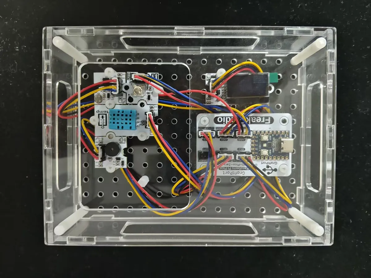
This case requires connecting 5 modules. Please connect them correctly according to the corresponding relationship below to ensure that the pins are not connected incorrectly:
2.1 Wiring of DHT11 Temperature and Humidity Sensor
We connect the DHT11 temperature and humidity sensor module to the development board, and the corresponding relationship is as follows:
Development Board Pins | Module Pins | Description |
Pin 12 / GPIO9 |
| 1-Wire communication pin |
2.2 Wiring of GL5516 Light Intensity Sensor
We connect the GL5516 light intensity sensor module to the AIN0 interface of the development board, and the corresponding relationship is as follows:
Development Board Pins | Module Pins | Description |
GPIO26 |
| Light intensity analog signal input pin, used to read the analog value of light intensity |
GPIO19 |
| - |
2.3 Wiring of SSD1306 OLED Display
We connect the SSD1306 OLED display module to the I2C0 interface of the development board, and the corresponding relationship is as follows:
Development Board Pins | Module Pins | Description |
Pin 4 |
|
|
Pin 5 |
|
|
2.4 Wiring of Passive Buzzer Module
We connect the passive buzzer module to the DIO0 interface of the development board, and the corresponding relationship is as follows:
Development Board Pins | Module Pins | Description |
GPIO7 |
| PWM output pins and high/low level output pins of MCU |
GPIO8 |
| - |
2.5 Piranha LED Module Wiring
We connect the Piranha LED light module to the DIO0 interface of the development board, and the corresponding relationship is as follows:
Development Board Pins | Module Pins | Description |
GPIO3 |
| Level output/PWM output pins on MCU |
GPIO2 |
| Do not use |
📌 Wiring Tips
- The GND pins of all modules must be connected to the GND of the development board to ensure a common ground for the circuit;
- The I2C pins (SDA/SCL) of the OLED must be connected correctly; otherwise, the screen will not be able to display anything.
3. Program Description
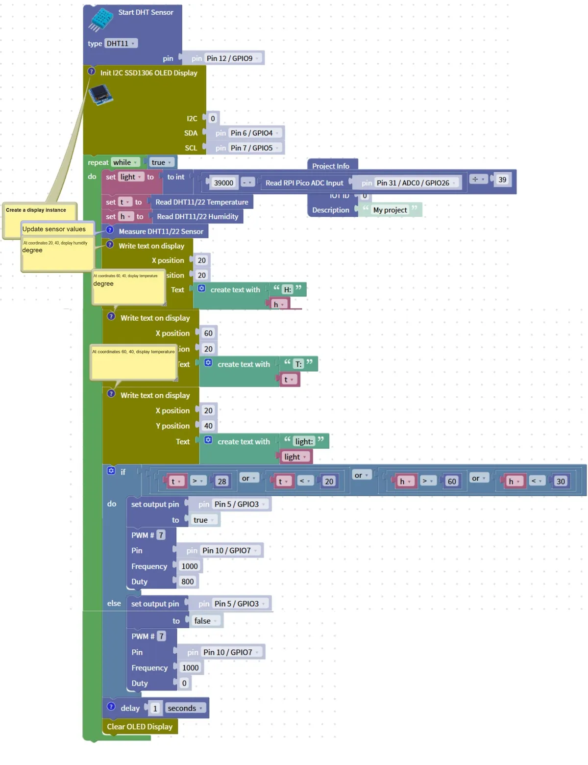
The core of this case lies in the workflow of "real-time data collection → data display → threshold judgment → exception alarm". We break it down in the order of building block assembly, so even beginners can follow along step by step:
- Hardware Initialization Block (preliminary step, hidden but critical)
- DHT11 Initialization: By default, Pin 12/GPIO9 is configured as input mode for reading temperature and humidity data;
- OLED Initialization: Configure the I2C0 interface (SDA= Pin6, SCL= Pin7) and set the screen size (128×64);
- Buzzer / LED Initialization: Set the corresponding pins to output mode to prepare for peripheral control.
- Infinite Loop Block (
repeat while true)- Function: Keeps the logic of "collection → display → judgment → alarm" running continuously, with data refreshed once per second.
- Location: All function blocks must be placed inside this loop.
- Data Acquisition Block
- Read temperature and humidity: use the
Read DHT11 TemperatureandRead DHT11 Humidityblocks to obtain the current values; - Read light intensity: Use the
Read RPI Pico ADC Inputblock to read the analog value of GL5516 (Pin31).
- Read temperature and humidity: use the
- OLED Display Building Block
- Temperature Display: Display "T: XX℃" at the screen coordinate (20,0);
- Display Humidity: Display "H: XX%" at coordinates (20,20);
- Display light intensity: Display "L: XX" at coordinates (20,40);
- Refresh the screen: Use the
Clear OLED DisplayandShow OLEDblocks to update data in real time.
- Threshold judgment block (
ifmulti-condition judgment)- Configuration: Judge "Temperature < 20 OR Temperature > 28 OR Humidity < 40 OR Humidity > 60 OR Light Intensity < 50";
- Function: An alarm operation will be triggered as long as any item goes beyond the comfort zone.
- Alarm trigger block (
ifwithin the branch)- Buzzer Beep: Use the
PWM #6block to output a 3000Hz PWM signal to make the buzzer emit a prompt tone; - LED blinking: Use the
set output pinblock to toggle the LED between on and off states; - Delay debounce: add
a delay of 200 millisecondsto avoid frequent alarm triggering.
- Buzzer Beep: Use the
- Normal state block (
elsebranch, optional)- If the environment is within the comfort zone, you can add
set output pinto keep the LED on steadily and stop the buzzer from sounding.
- If the environment is within the comfort zone, you can add
Program running effect:
- Initial state: The OLED displays the current temperature, humidity and light intensity, the LED is always on, and the buzzer is muted;
- Exception Trigger: When the data exceeds the comfort zone, the buzzer will beep softly, the LED will flash, and the abnormal data on the OLED will be highlighted;
- Return to normal status: Once the data returns to the normal range, the alarm will stop automatically, and the LED will resume steady-on illumination.
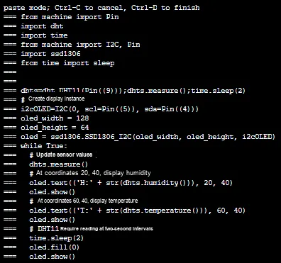
Directly importable building blocks:
Smart classroom environment little steward.xml 24 KB
A Beginner's Guide to Avoiding Common Pitfalls
- OLED screen not displaying?
- Check whether the SDA/SCL pins are connected correctly (Pin6/Pin7) and whether the I2C library is installed properly;
- Confirm that the screen is properly powered, and you can try restarting the development board before testing again.
- Sensor data abnormal / not moving?
- The DHT11 requires a 2-second warm-up time, remember to add it in the program
delay 2 secondsas the initialization delay; - GL5516 is an analog sensor whose value changes with light intensity; if the value remains unchanged, check whether the wiring is loose.
- The DHT11 requires a 2-second warm-up time, remember to add it in the program
- Alarm not triggered / Abnormal triggering?
- Check whether the threshold condition is written incorrectly (for example, writing "AND" instead of "OR");
- Check whether the pins of the buzzer / LED match the configuration in the program.
✨ Interactive Mini Quiz
- Think about it: If we want to change the "comfort zone" to "temperature 18~26℃, humidity 30~70%", which block in the program needs to be modified?
- Try it out: Add a "normal status indicator" to the system — when the ambient conditions are within the comfortable range, the LED stays on steadily, and when they go beyond the range, it blinks. Can you incorporate this logic into the code?