
Contents
Young makers, safety always comes first!
Today, we are going to create an extremely practical "Fire Safety Sentinel" 🚒 — it works just like a home smoke alarm, capable of keenly "detecting" open flames and smoke. Once a hazard is detected, it will trigger an alarm, and you can also manually silence the alarm via a button. Through this project, we will not only learn how to combine and use different sensors, but also develop a strong awareness of fire safety~
1. Case Introduction
1.1 Modules Used
- Core Inputs: PT334 flame sensor module (for open flame/flame identification), MQ-1 smoke sensor module (for smoke/combustible gas detection), mechanical key module (for alarm cancellation);
- Core Output: Passive buzzer module (simulating fire alarm sound).
1.2 Creative Gameplay
This "little sentry" can stand guard 24 hours a day to monitor hazards:
- Normal state: When there is no open flame or smoke, the buzzer remains silent;
- Hazard Trigger: When flame or smoke is detected, the passive buzzer will continuously emit a loud alarm sound (simulating a fire alarm);
- Alarm reset: Press the mechanical button to stop the buzzer (simulates the operation of "confirming the hazard and completing the handling");
- Re-detection: After the alarm is cleared, the system will continue monitoring; if the hazard still exists, the alarm will be triggered again.
1.3 Core Learning Points
- Master dual-sensor collaborative detection (flame + smoke, covering the two core hazard signals of fires);
- Understand the trigger logic of security alerts ("OR condition" judgment: an alert will be triggered as long as there is any hazard signal);
- Master clearing the alarm via key press interrupt (no need to wait for the loop to end, the alarm stops immediately when the key is pressed);
- Proficient in using infinite loops + state reset (resume monitoring after the alarm is cleared without interrupting the "sentry duty");
- Develop programming thinking for fire safety scenarios (integrating code with real-world safety requirements).
2. Wiring Instructions
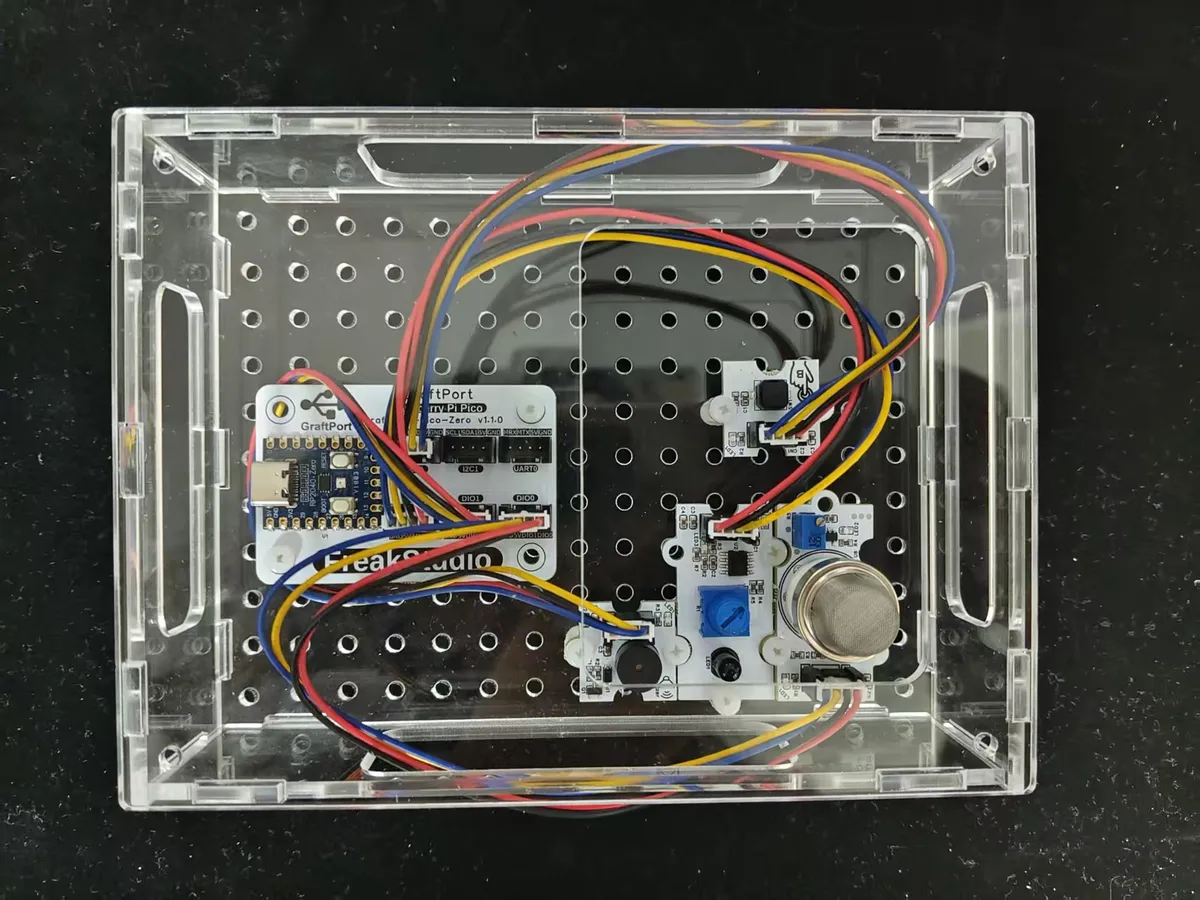
This scenario requires connecting 4 modules, and the wiring method of each module is clearly broken down, so even beginners can get the connection right on the first try:
1. Wiring of PT334 Flame Sensor
We connect the PT334 flame sensor module to the AIN0 interface of the development board, and only use the DIN pin (the second pin of the module's interface) for threshold judgment.
2. Wiring of MQ-1 Smoke Sensor
We connect the MQ-1 smoke sensor module to the DIO0 interface of the development board, and only use the DIN port (the second pin of the interface) for threshold judgment.
3. Wiring of the mechanical key module
We connect the mechanical key module to the I2C0 interface of the development board.
4. Wiring of Passive Buzzer Module
We connect the passive buzzer module to the DIO1 interface of the development board.
📌 Wiring Tips
- The GND of all modules
- The MQ-1 smoke sensor needs to be preheated for 2-3 minutes for its first use; otherwise, the detection result will be inaccurate.
- It is recommended to enable the pull-up resistor (Pull-up= true) for mechanical buttons to avoid false triggers caused by level jitter.
Important Wiring Knowledge
✅ Why can a keypad (digital input module) be connected to an I2C interface?
Essentially, the I2C interface is a "multi-purpose universal channel": it can not only transmit dedicated I2C signals, but also recognize simple "high level / low level" just like a DIO port — just like a multi-functional classroom at school, which can host professional courses requiring projectors as well as regular Chinese language classes. Since the key module only needs to transmit the simple signal of "pressed = low level / not pressed = high level", connecting it to the I2C interface works perfectly fine.
❌ Why can't I2C modules (such as OLED displays) be connected to ordinary DIO ports?
The I2C module requires the transmission of "bidirectional data with clock synchronization" — just as dedicated microscopes and beakers are required for lab classes — whereas ordinary DIO ports can only recognize simple high/low logic levels and lack the critical function of "clock synchronization". Connecting them would be equivalent to conducting a chemistry experiment on a regular classroom blackboard: without the core equipment, it is impossible to function properly at all.
Brief summary: Simple "digital signal modules"(buttons, LEDs, ordinary sensors) can be connected to the I2C interface as a makeshift solution, but I2C-specific modules (such as OLED displays, PCA9685 servo drivers) can only be connected to the I2C interface and cannot be connected to ordinary DIO ports!
3. Program Description
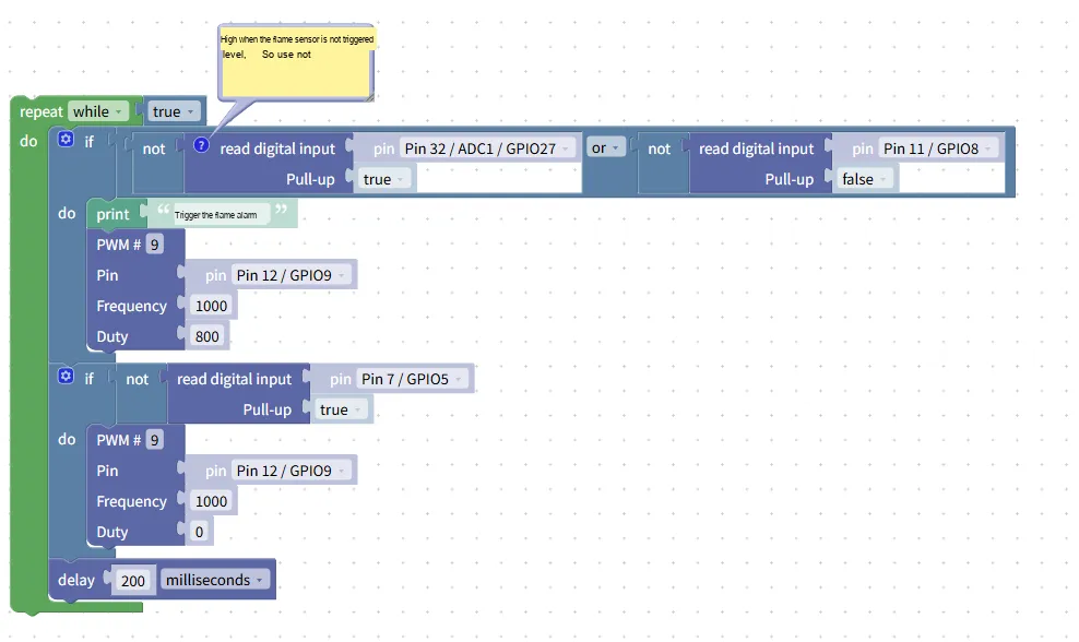
The core of this case follows the logic of "real-time monitoring → hazard alarm → button release → continuous standby", which we break down in the order of building block assembly so that even beginners can understand it step by step:
- hardware initialization block
- Sensor Initialization: Set PT334 (Pin10) and MQ-1 (Pin12) to "input mode + pull-up resistor" to ensure stable voltage level;
- Key initialization: Set the mechanical key (Pin28) to "input mode + pull-up resistor", and enable the "falling edge interrupt"(triggered immediately when the key is pressed);
- Buzzer initialization: Set Pin 9 to "output mode + PWM function" to prepare for outputting the alarm sound.
- Global state variables (hidden but core)
- Add
an alarm_statevariable with its initial value set tofalse(meaning "no alarm"); - Function: Remember whether the current state is an alarm state, so as to facilitate the release via key press.
- Add
- Infinite Loop Block (
repeat while true)- Function: Enables the system to continuously monitor flame and smoke signals, standing guard without ever stopping;
- Location: All detection and alarm logics are placed within this loop.
- Danger detection and judgment block (
ifor conditional judgment)- Configuration: Judge "PT334 detects flame OR MQ-1 detects smoke"(i. e.
read digital input Pin10 = false OR read digital input Pin12 = false); - Function: The alarm will be triggered as long as there is any danger signal.
- Configuration: Judge "PT334 detects flame OR MQ-1 detects smoke"(i. e.
- Alert trigger block (
within the ifbranch)- Set alarm status: set
alarm_statetotrue; - Buzzer Ring: Use the
PWM #6block to output a PWM signal of 2000Hz with a 50% duty cycle, making the buzzer continuously emit a loud alarm sound; - Terminal prompt: add
print "Danger detected! Fire alarm triggered"to facilitate checking the trigger cause.
- Set alarm status: set
- Button to Cancel Alarm Block (Interrupt Handling)
- Configuration: Add an "External Event (Interrupt)" block to the mechanical key, with the trigger mode set to
IRQ_FALLING(triggered when the key is pressed); - Interrupt Context Operations:
- Set
alarm_statetofalse; - Turn off the buzzer (
set output pin Pin9 to false); print "Alarm cleared, confirm hazard handled".
- Set
- Configuration: Add an "External Event (Interrupt)" block to the mechanical key, with the trigger mode set to
- Normal state block (
elsebranch)- If no hazard is detected, set
alarm_statetofalse, turn off the buzzer, andprint "Environment is safe, continuous monitoring in progress"; - Add
a delay of 500 millisecondsto lower the loop frequency and reduce the power consumption of the development board.
- If no hazard is detected, set
Program running effect:
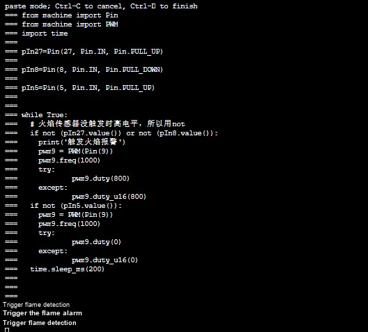
- Initial state: the buzzer is muted, and the terminal prints "Environment is safe, continuous monitoring in progress";
- Hazard Trigger: Bring a lighter close to the flame sensor / expose the MQ-1 module to smoke, the buzzer will immediately emit a continuous alarm, and the terminal will display the prompt "Hazard Detected";
- Alarm reset: Press the mechanical button, the buzzer will stop sounding, and the terminal will prompt "Alarm has been reset";
- Continuous Monitoring: After the alarm is deactivated, the system continues to detect; if the hazard still exists, the alarm will be re-triggered after 3 seconds.
Directly importable building blocks:
Fire safety little sentinel.xml 6 KB
A Beginner's Guide to Avoiding Common Pitfalls
- Buzzer not sounding / low volume?
- Check whether the buzzer pin is connected to Pin9, and whether the PWM frequency is set to 1000-3000Hz (the loudest sound falls in this range);
- Make sure the VCC of the buzzer is connected to 5V; insufficient power supply will result in weak sound.
- Can the sensor fail to detect hazards?
- The PT334 flame sensor should be aligned with the open flame (do not keep it too far away; a distance of 5-10 cm is recommended) to avoid strong light interference;
- The MQ-1 smoke sensor needs to be preheated for 2-3 minutes first, then blow smoke gently onto it with a lighter (do not burn the module directly).
- Does pressing the button fail to deactivate the alarm?
- Check whether the key has the pull-up resistor enabled (Pull-up= true) and whether the pin is connected to Pin28;
- Confirm that the interrupt trigger mode is
IRQ_FALLING, notIRQ_RISING.
✨ Interactive Mini Quiz
- Think about it: What will happen if the "OR" in hazard detection is changed to "AND"? (Answer: The alarm will only be triggered when both flame and smoke are detected simultaneously, which reduces safety, because a single flame or smoke alone is also a danger signal!)
- Try it out: Add an "emergency indicator light" to the case — when the alarm is triggered, the piranha LEDs will flash synchronously. Can you add the LED block into it?