
Young makers, we've learned how to use the buttons, LEDs and sensors separately one by one, and now it's finally time to "combine all the skills to strike"! Today's button-toggle LED indicator system is the most classic introductory comprehensive case — just like the light switch at home: press once to turn the light on, press again to turn it off, switching back and forth in a loop. Through this case, you can fully master the complete logic of "button detection + state storage + LED control", laying a solid foundation for more complex projects later~
1. Case Introduction
Modules Used
- Core Input: Mechanical key module (responsible for "sending commands");
- Core output: Piranha LED light module (responsible for "providing feedback").
Creative Gameplay
By pressing the mechanical key, the "toggle" state switching of the LED lamp is realized, which perfectly restores the logic of daily light switches:
- Press the button for the first time → the LED changes from off to on;
- Press the button again → the LED turns from on to off;
- Press the button repeatedly to toggle between the on and off states.
Core Learning Points (Essential for Beginners to Master)
- Simulate the real scenario of "button-controlled switches"(such as light switches, remote control buttons);
- Learn key level detection and anti-shake processing (to avoid misoperations caused by key "jitter");
- Use a variable to store the LED state (i. e., keep track of "whether the current light is on or off");
- Master the logic of conditional judgment + state flipping (core! Implement the "changes once per press" function);
- Proficiently control LED output and status switching.
2. Wiring Instructions
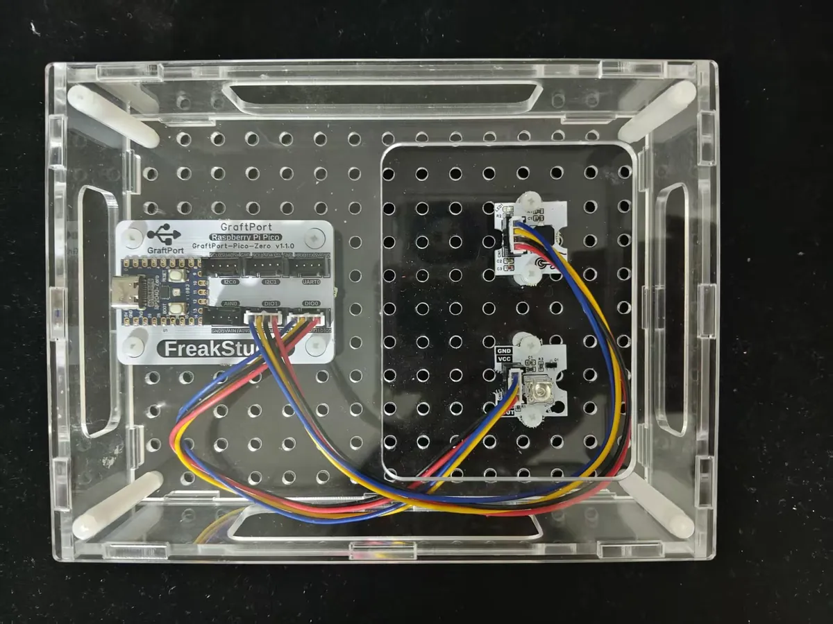
This case requires connecting two modules, and the wiring is extremely simple — just connect them according to the corresponding relationships below:
Connect using the Piranha LED light module to DIO0 interface:
Development Board Pins | Module Pins | Description |
Pin 7 |
| Level output/PWM output pins on MCU |
Pin 8 |
| Do not use |
We connect the mechanical key module to the DIO1 interface:
Development Board Pins | Module Pins | Description |
Pin 9 |
| Level signal input pin after key press/release |
Pin 10 |
| - |
3. Program Description
The core of this case is "remember the current state of the LED, and toggle it once every time the button is pressed". We will break it down according to the "building block assembly sequence", so even beginners can understand it step by step:
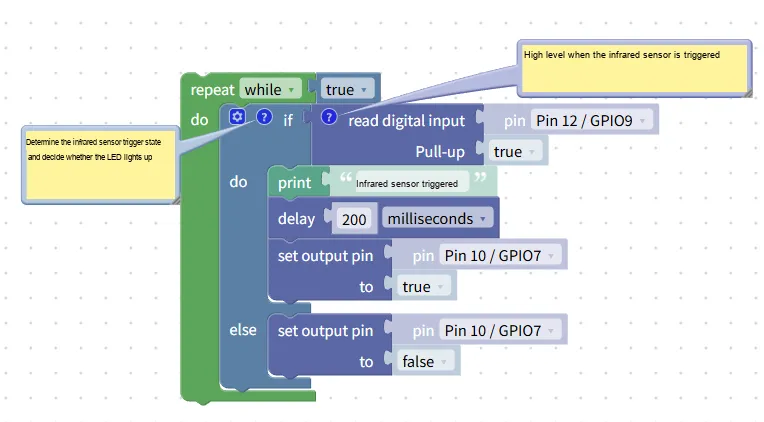
- Hardware Initialization Block (hidden / pre-requisite, required step)
- Infrared sensor initialization: by default,
Pin 12/GPIO9is configured as "input mode" + "pull-up resistor"(Pull-up= true), which functions to keep the sensor outputting a stable level and prevent erratic fluctuations. - LED initialization: By default,
Pin 10/GPIO7is set to "output mode", which enables the development board to control the on/off state of the LED.
- Infrared sensor initialization: by default,
- Infinite Loop Block (
repeat while true)- Function: It enables the subsequent "detection + control" operation to be executed repeatedly (just like we keep staring at the door to see if anyone is coming), instead of stopping after being executed only once.
- Position: All detection and control blocks must be placed inside this loop block.
- Human body detection block (
if read digital input)- Configuration:
pin=Pin 12/GPIO9,Pull-up=true - Function: Detect the level signal of the infrared sensor to determine whether there is a human body approaching.
- Human body proximity: The sensor reflects infrared signals and outputs a high level; the block judges this as "true" and executes the operations inside.
- Human body is far away: the sensor has no reflected signal and outputs low level, the block judges it as "false" and will not execute the operations inside.
- Configuration:
- Action block after trigger (in the if branch within the loop)
Set output pin Pin10/GPIO7 to true: The LED turns on (sends a high level to the LED to power it up and make it light up);print "Infrared sensor triggered": Print a prompt in the terminal to let us easily view the feedback "Human body detected";delay 200 milliseconds: debounce delay (prevents sensor signal jitter that would cause the LED to flicker or duplicate prompt printing, equivalent to "stabilize for 200 milliseconds before making a judgment").
- No human operation detected (implicit/optional else branch)
- To explicitly control turning off the light, you can add an
ifblock followed by anelseblock, and placeset output pin Pin10/GPIO7 to falseinside the else block; - Function: When the human body moves away, the LED light will turn off automatically (send a low level to the LED to cut off power and turn it off).
- To explicitly control turning off the light, you can add an
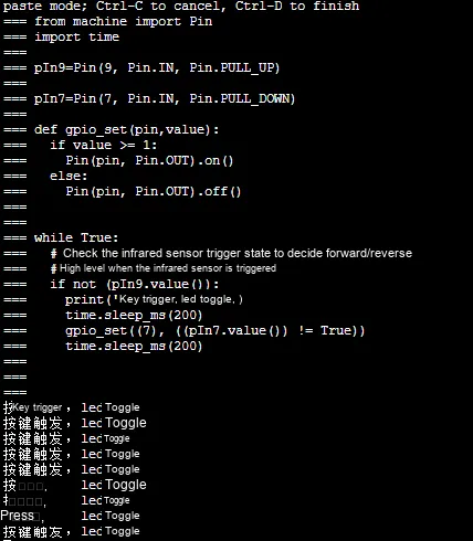
After running the program:
- Initial state: The LED is off, and the terminal displays "LED status: Off";
- When the button is pressed for the first time: the LED turns on, and the terminal prints "LED status: on";
- When the key is pressed for the second time: the LED turns off, and the terminal prints "LED status: Off";
- Repeatedly pressing the key: the LED switches steadily between on and off, without jitter or malfunction.
A Beginner's Guide to Avoiding Common Pitfalls
- LED not lighting up / not turning off?
- Check whether the LED pins are connected to GPIO7 and whether the output pins in the program match;
- Confirm that the toggle logic for the variable
led_stateis written correctly (it must benot led_state).
- Is there no response when pressing the button?
- Check whether the key pin is connected to GPIO9 and whether the pull-up resistor is enabled (Pull-up= true);
- Forgot to add the debounce delay, which resulted in key jitter being ignored; be sure to add a 200ms delay.
- Is the LED flashing repeatedly?
- When the key is released, the "wait for release" process is not implemented. Just add the following code in the program:
while not button.value (): time.sleep (0.01)to fix this issue.
- When the key is released, the "wait for release" process is not implemented. Just add the following code in the program:
✨ Interactive Mini Quiz
- Think about it: If you set the initial value of the state variable to
true, will the LED be on or off initially after the program runs? (Answer: On! Becauseled_state= true, the LED pin outputs a high level) - Try it: Add a "buzzer feedback" to the case – make the buzzer beep once when the button is pressed. Can you add the buzzer block into it?
xml files can be directly imported into the building blocks: