
Contents
So far, we have learned how to send commands and data to the OLED, and successfully lit up some of its pixels. However, getting the OLED to display characters or patterns is not as straightforward as simply turning on certain pixels.
Looking back at the drawPixels () code from the previous section, we lit up a specific area of the OLED screen by sending dedicated commands to set the page address and column address and then populating the data. So what is the underlying logic behind this? Why does the OLED require addressing in terms of pages and columns? And how are characters displayed within this dot matrix structure?
// Light up some pixels
void drawPixels() {
  sendCommand(0xB0);  // Select page 0 (0~7)
  sendCommand(0x00);  // Set the lower 4 bits of the column (start column)
  sendCommand(0x10);  // Set the upper 4 bits of the column

  for (int i = 0; i < 16; i++) {  // Draw 16 columns of pixels
    sendData(0xFF);  // 0xFF = light up 8 pixels (all white)
  }
}
Without a doubt, to truly make an OLED screen display characters or patterns, we need to gain an in-depth understanding of the fundamental principles behind OLED displays, break down the complete process of OLED character display step by step from pixel arrangement to character mapping, and ultimately achieve custom text output!
1. Basic Principles of OLED Display
1.1 Core Idea of Dot-Matrix Display
An OLED screen is composed of pixels, and each pixel can independently display different brightness levels or colors. The resolution of an OLED screen is usually expressed in the format of "columns × rows"; for example, 128×64 means there are 128 columns and 64 rows of pixels on the screen. Each pixel serves as the basic unit for displaying content.
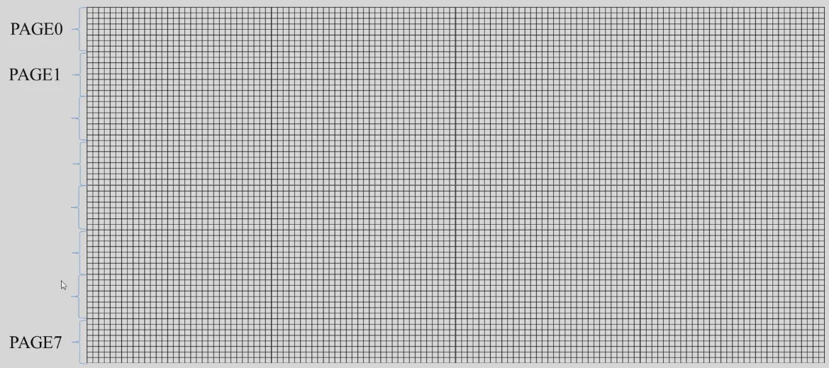
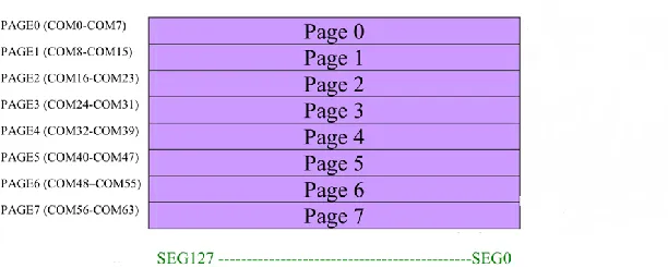
To make it easier to control these pixels, the OLED screen divides the entire screen into multiple small blocks. Taking a screen with a resolution of 128×64 as an example, it is divided into 8 pages (PAGE0 to PAGE7), each page contains 128 columns (corresponding to 128 bytes), and these bytes control the columns (SEG) of the screen.
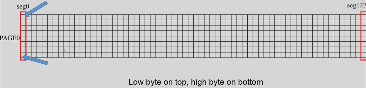
Each byte (8 bits) represents the state of the 8 pixels of one column (SEG). Each bit in the byte corresponds to one pixel, determining whether that pixel is on or off:
- 1 indicates that the pixel is lit up.
- 0 indicates that the pixel is turned off.
The low bit (LSB) of the byte corresponds to the pixels above, and the high bit (MSB) corresponds to the pixels below.
For example:
- Byte
0xFF(binary11111111) will turn on all 8 pixels in this column. - Byte
0x00(binary00000000) will turn off all 8 pixels in this column.
1.2 Screen Display of Characters or Patterns
On an OLED screen, the display of characters and patterns is achieved by configuring these bytes. The display area of each character or pattern on the screen is controlled by a set of bytes. For instance, a character may require a pixel area of 8 columns by 16 rows, so 16 bytes (each controlling 8 rows of pixels) are used to describe the display content of this character.
For Chinese characters, they usually occupy 16×16 pixels, which means each Chinese character is controlled by 32 bytes. In this way, every character or Chinese character on the screen is presented by controlling the on-off state of different bytes.
Typically:
- A Chinese character occupies 16×16 pixels.
- A single character occupies 16×8 pixels.
Let's think about how many Chinese characters or characters the entire OLED screen can display. The resolution of the OLED is 128×64, which divides the screen into 128 columns × 64 rows of pixels.
- If Chinese characters are displayed: each Chinese character occupies 16 columns × 16 rows of pixels, so the screen can display 8 columns × 4 rows of Chinese characters, which is 32 Chinese characters.
- For displayed characters: each character occupies 8 columns × 16 rows of pixels, so the screen can display 16 columns × 4 rows of characters, which totals 64 characters.
1.3 Principle of OLED Screen Display Control
As we already know, the values of these bytes form the core of the content displayed on the OLED screen. So how are these bytes read and executed by the OLED screen? Actually, these bytes are stored in the OLED screen's Graphic Display Data RAM (GDDRAM), and the SSD1306 chip integrated in the OLED module periodically reads the data in the GDDRAM at a preset refresh rate, which is typically 60Hz or 72Hz. Each byte corresponds to a column of pixels on the screen, and each bit in the byte determines the on/off state of one pixel in that column.After the SSD1306 reads data, it converts the data into driving voltage, and controls the pixels to turn on or off through the charge pump circuit of the OLED. By continuously updating the display memory data, dynamic display effects such as scrolling and flipping can be realized.
2. Briefly describe the process of OLED displaying characters
Each character on an OLED screen typically occupies a fixed pixel area, usually 16x8 pixels. The display of each character is controlled by a byte array, where each bit of the bytes corresponds to the on/off state of one pixel.
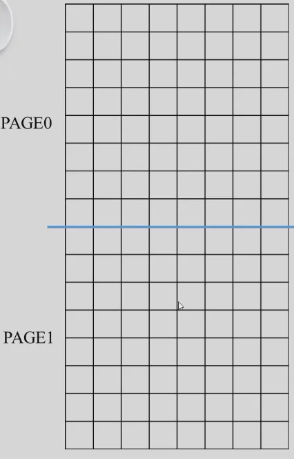
To correctly display a character on an OLED, follow the steps below:
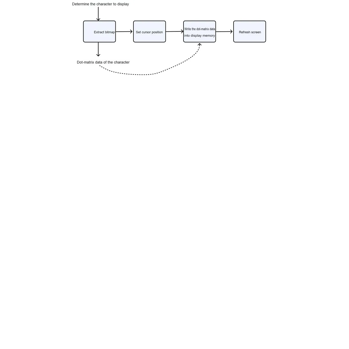
- Determine the dot matrix data of the character (modulo extraction)
Modulo extraction essentially refers to converting the pattern of a character into binary or hexadecimal dot matrix data, so that the data can be stored and applied for OLED display. Such dot matrix data can be obtained either by manually analyzing the pixels of the character or via modulo extraction software. - Specify the position for character display (set the cursor)
When displaying characters on an OLED screen, it is necessary to first determine the starting position, that is, specify the horizontal and vertical coordinates (column address and page address) of the cursor. - Write the dot matrix data to the OLED display memory byte by byte
Write the dot matrix data of the character to the display memory byte by byte. - OLED refreshes the screen to display characters
The OLED controller reads data from the video memory, causing the OLED to redraw the screen content and make the characters visible.
2.1 Determine the dot matrix data of the character
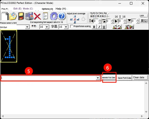
Taking the character '1' as an example, the following is the dot matrix diagram of the character '1':
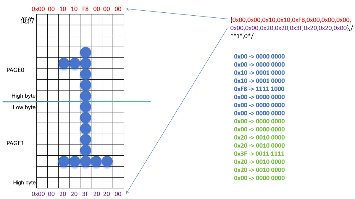
2.2 Manual Mold Removal
Following the rule that the lower bit is at the top and the higher bit is at the bottom, the 8 bits of each byte sequentially control the on/off state of one column of pixels. Below, we will convert the binary data corresponding to the character '1' into hexadecimal data column by column:
0000 0000 -> 0x00
0000 0000 -> 0x00
0001 0000 -> 0x10
0001 0000 -> 0x10
1111 1000 -> 0xF8
0000 0000 -> 0x00
0000 0000 -> 0x00
0000 0000 -> 0x00

0000 0000 -> 0x00
0000 0000 -> 0x00
0010 0000 -> 0x20
0010 0000 -> 0x20
0011 1111 -> 0x3F
0010 0000 -> 0x20
0010 0000 -> 0x20
0000 0000 -> 0x00
2.3 Obtaining Font Matrix in Font Matrix Generation Software
Do we have to calculate these dot matrix data manually? When it comes to converting character dot matrix into OLED display byte data, there is an easier way, which is to use a font extraction tool to directly convert the shape of a character into the corresponding dot matrix data. With these data, you can complete the character display operation.
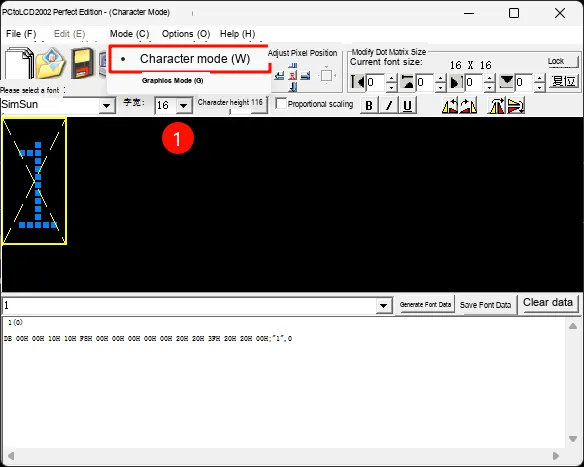
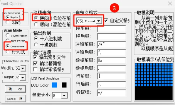
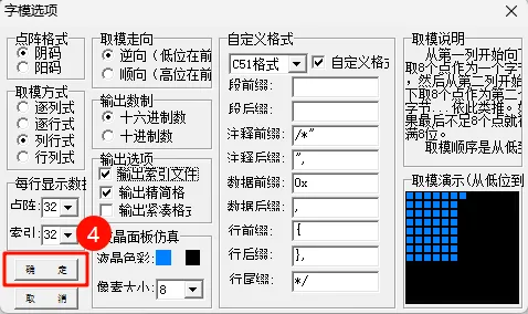
Select "Character Mode" -> Open the options for configuration -> Set "Negative Code", "Row-Column Order", "Reverse", "C51 Format" -> Click "Confirm" -> Enter the character '1' in the input box -> Click "Generate Font Matrix" -> Obtain the font matrix of '1' in the output box below.
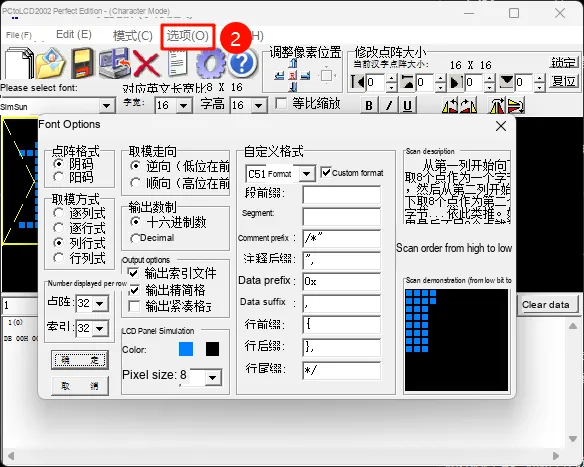
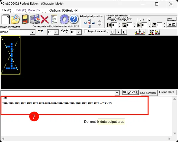
The final obtained result is as follows:
{0x00,0x00,0x10,0x10,0xF8,0x00,0x00,0x00,0x00,0x00,0x20,0x20,0x3F,0x20,0x20,0x00},/*"1",0*/
3. Software Implementation Procedures
3.1 Initialize the OLED Screen
Before performing any display operation on an OLED screen, initialization must be carried out first to ensure that the OLED is in the correct operating mode.
During the initialization process, the display first needs to be turned off to prevent abnormal display during initialization. Next, configure parameters such as multiplexing rate, display offset, and start line address to ensure correct pixel mapping. Then, set the column scan direction and segment remapping mode to adjust the display orientation and arrangement. After that, adjust display parameters such as contrast to optimize the visual effect. Finally, turn on the display to put the OLED into normal operating state and prepare it to receive subsequent display data. Below is a specific example of the initialization code:
void oledInit() {
  sendCommand(0xAE);  // Turn off the display
  sendCommand(0xA8);  // Set the multiplex ratio
  sendCommand(0x3F);  // 64 rows
  sendCommand(0xD3);  // Set the display offset
  sendCommand(0x00);
  sendCommand(0x40);  // Set the start line address
  sendCommand(0xA1);  // Set the segment remap
  sendCommand(0xC8);  // Set the column scan direction
  sendCommand(0xDA);  // Set the hardware pin configuration
  sendCommand(0x12);
  sendCommand(0x81);  // Set the contrast
  sendCommand(0x7F);
  sendCommand(0xA4);  // Turn on the display
  sendCommand(0xAF);  // Turn on the screen
}
This code is configured in accordance with the datasheet of the OLED controller to ensure that the OLED enters a normal working state and can correctly display characters or images.
3.2 Set Cursor Position
Before displaying characters on an OLED screen, the cursor position must be set first to specify the starting display area of the characters. The setting of the cursor position mainly includes the following steps:
- Page Address Setting
The pixels of an OLED screen are usually divided into pages, with each page corresponding to 8 rows (for a 64-row screen, there are 8 pages in total). Before writing character data, you need to specify the target page first. - Set Column Address
Each character occupies a certain column width (e. g., 8 or 16 columns) on the OLED screen, so it is necessary to specify the starting column address of the character. The OLED uses two commands to set the lower 4 bits and upper 4 bits of the column address respectively, so as to cover the column range from 0 to 127.
In the displayChar () function, the cursor position is set by sending page address and column address commands:
// Set the page address (row number)
sendCommand(0xB0 + page);

// Set the column address (lower 4 bits)
sendCommand(0x00 + (column & 0x0F));

// Set the column address (upper 4 bits)
sendCommand(0x10 + ((column >> 4) & 0x0F));
This code ensures that characters are correctly aligned to the specified position, so that the subsequently written dot matrix data can be accurately displayed on the OLED screen.
3.3 Write the dot matrix data into the OLED video memory byte by byte
1. Create a character data array
Each character needs to be converted into a format understandable by the OLED screen via a dot matrix, which we have previously generated manually or using a font extraction tool.
In the code, we use an array to represent the 16×8 dot matrix data for the character '1'. Each character occupies 2 pages (64 pixels). Below is the dot matrix data for the '1' character (8 rows * 2 columns):
uint8_t font[] = {
  // Upper half (upper 8 rows)
  0x00, 0x00, 0x10, 0x10, 0xF8, 0x00, 0x00, 0x00,
  // Lower half (lower 8 rows)
  0x00, 0x00, 0x20, 0x20, 0x3F, 0x20, 0x20, 0x00
};
2. Write control byte:
When displaying characters on an OLED screen, a control byte must first be sent to inform the OLED screen that the subsequent content to be written is data rather than a command. In communication, 0x00 is typically used to indicate command mode, while 0x40 denotes data mode.
void sendCommand(uint8_t cmd) {
  Wire.beginTransmission(OLED_ADDR);
  Wire.write(0x00);  // Control byte: command
  Wire.write(cmd);
  Wire.endTransmission();
}

void sendData(uint8_t data) {
  Wire.beginTransmission(OLED_ADDR);
  Wire.write(0x40);  // Control byte: data
  Wire.write(data);
  Wire.endTransmission();
}
3. Write character data
After setting the cursor position, we write the dot matrix data of the characters to the OLED screen byte by byte. Via sendData (), each byte (pixel data) is transmitted to the OLED for display.
The character '1' is split into two parts: the upper half and the lower half, which are then written into the corresponding pages:
// Write the upper half
sendCommand(0xB0 + page);  // Set the page address
sendCommand(0x00 + (column & 0x0F));  // Set the column low address
sendCommand(0x10 + ((column >> 4) & 0x0F));  // Set the column high address
for (uint8_t i = 0; i < 8; i++)
{
  sendData(font[i]);  // Write the dot-matrix data (upper half)
}

// Write the lower half
sendCommand(0xB0 + page + 1);  // Set the page address
sendCommand(0x00 + (column & 0x0F));  // Set the column low address
sendCommand(0x10 + ((column >> 4) & 0x0F));  // Set the column high address
for (uint8_t i = 8; i < 16; i++)
{
  sendData(font[i]);  // Write the dot-matrix data (lower half)
}
3.4 Refresh the Screen
If the OLED screen does not support automatic refresh, you may need to manually trigger a refresh operation to update the displayed content.
If your OLED screen does not refresh automatically, you can use sendCommand (0xAF) to force a display refresh.
4. Final Implementation Code
In this section, we respectively use software I2C and hardware I2C to implement the control of the OLED screen, and complete the basic character display function.
4.1 Software Implementation of I2C
// OLED parameters
#define OLED_ADDR 0x3C  // OLED I2C address
#define SCL_PIN 22      // SCL pin
#define SDA_PIN 21      // SDA pin

// Initialize the OLED screen
void oledInit() {
  sendCommand(0xAE);  // Turn off the display
  sendCommand(0xA8); sendCommand(0x3F);  // Set the multiplex ratio (64 rows)
  sendCommand(0xD3); sendCommand(0x00);  // Set the display offset
  sendCommand(0x40);  // Set the start line address
  sendCommand(0xA1);  // Set the segment remap
  sendCommand(0xC8);  // Set the column scan direction
  sendCommand(0xDA); sendCommand(0x12);  // Set the hardware pin configuration
  sendCommand(0x81); sendCommand(0x7F);  // Set the contrast
  sendCommand(0xA4);  // Turn the global display on
  sendCommand(0xA6);  // Normal display mode
  sendCommand(0xAF);  // Turn on the display
}

// Software I2C start condition
void I2C_Start() {
  digitalWrite(SDA_PIN, HIGH);
  digitalWrite(SCL_PIN, HIGH);
  delayMicroseconds(5);
  digitalWrite(SDA_PIN, LOW);  // SDA low
  delayMicroseconds(5);
  digitalWrite(SCL_PIN, LOW);  // SCL low
}

// Software I2C stop condition
void I2C_Stop() {
  digitalWrite(SDA_PIN, LOW);  // SDA low
  digitalWrite(SCL_PIN, HIGH); // SCL high
  delayMicroseconds(5);
  digitalWrite(SDA_PIN, HIGH); // SDA high
}

// Software I2C: send one byte
void I2C_WriteByte(uint8_t data) {
  for (int i = 7; i >= 0; i--) {
    digitalWrite(SDA_PIN, (data >> i) & 0x01);  // Set SDA
    digitalWrite(SCL_PIN, HIGH);               // Generate clock rising edge
    delayMicroseconds(5);
    digitalWrite(SCL_PIN, LOW);                // Clock falling edge
    delayMicroseconds(5);
  }
  // Receive ACK
  pinMode(SDA_PIN, INPUT);  // Set SDA as input
  digitalWrite(SCL_PIN, HIGH);
  delayMicroseconds(5);
  digitalWrite(SCL_PIN, LOW);
  pinMode(SDA_PIN, OUTPUT); // Restore SDA as output
}

// Send a command to the OLED
void sendCommand(uint8_t command) {
  I2C_Start();
  I2C_WriteByte(OLED_ADDR << 1);  // Send device address + write operation
  I2C_WriteByte(0x00);            // Control byte: command mode
  I2C_WriteByte(command);         // Send command
  I2C_Stop();
}

// Send data to OLED
void sendData(uint8_t data) {
  I2C_Start();
  I2C_WriteByte(OLED_ADDR << 1);  // Send device address + write operation
  I2C_WriteByte(0x40);            // Control byte: data mode
  I2C_WriteByte(data);            // Send data
  I2C_Stop();
}

// Display a character on the OLED
void displayChar(uint8_t page, uint8_t column, char c) {
  // Assume a 16×8 dot matrix for '1' (16 pixels high, 8 pixels wide)
  uint8_t font[] = {
    0x00, 0x10, 0x10, 0xF8, 0x00, 0x00, 0x00, 0x00,  // Upper half
    0x00, 0x20, 0x20, 0x3F, 0x20, 0x20, 0x00, 0x00   // Lower half
  };

  // Set page address and column address
  sendCommand(0xB0 + page);                   // Set the page address
  sendCommand(0x00 + (column & 0x0F));        // Set the column low address
  sendCommand(0x10 + ((column >> 4) & 0x0F)); // Set the column high address

  // Write the upper half of the dot matrix data
  for (int i = 0; i < 8; i++) {
    sendData(font[i]);
  }

  // Set the next page address
  sendCommand(0xB0 + page + 1);               // Set the page address
  sendCommand(0x00 + (column & 0x0F));        // Set the column low address
  sendCommand(0x10 + ((column >> 4) & 0x0F)); // Set the column high address

  // Write the lower half of the dot matrix data
  for (int i = 8; i < 16; i++) {
    sendData(font[i]);
  }
}

void setup() {
  pinMode(SCL_PIN, OUTPUT);  // Set SCL as output
  pinMode(SDA_PIN, OUTPUT);  // Set SDA as output

  oledInit();                // Initialize the OLED
  displayChar(0, 0, '1');    // Display character '1'
}

void loop() {
}
4.2 Hardware I2C Implementation
Compared with software I2C, hardware I2C uses Wire library for communication, which reduces the complexity of manual processing.
#include <Wire.h>

// OLED address and dimensions
#define OLED_ADDR 0x3C
#define OLED_WIDTH 128
#define OLED_HEIGHT 64

void setup() {
  Wire.begin();             // Initialize I2C
  oledInit();               // Initialize the OLED
  displayChar(0, 0, '1');   // Display character '1' at (0, 0)
}

void loop() {
}

void oledInit() {
  // Send initialization commands
  sendCommand(0xAE);  // Turn off the display
  sendCommand(0xA8);  // Set the multiplex ratio
  sendCommand(0x3F);  // 64 rows
  sendCommand(0xD3);  // Set the display offset
  sendCommand(0x00);
  sendCommand(0x40);  // Set the start line address
  sendCommand(0xA1);  // Set the segment remap
  sendCommand(0xC8);  // Set the column scan direction
  sendCommand(0xDA);  // Set the hardware pin configuration
  sendCommand(0x12);
  sendCommand(0x81);  // Set the contrast
  sendCommand(0x7F);
  sendCommand(0xA4);  // Turn on the display
  sendCommand(0xAF);  // Turn on the screen
}

void displayChar(uint8_t page, uint8_t column, char c) {
  // 16×8 dot matrix data for character '1' (16 pixels high, 8 pixels wide)
  uint8_t font[] = {
    // Upper half
    0x00, 0x00, 0x10, 0x10, 0xF8, 0x00, 0x00, 0x00,
    // Lower half
    0x00, 0x00, 0x20, 0x20, 0x3F, 0x20, 0x20, 0x00
  };

  // Write the upper half (corresponds to page = 0)
  sendCommand(0xB0 + page);  // Set the page address
  sendCommand(0x00 + (column & 0x0F));  // Set the column low address
  sendCommand(0x10 + ((column >> 4) & 0x0F));  // Set the column high address
  for (uint8_t i = 0; i < 8; i++) {
    sendData(font[i]);  // Write the dot-matrix data (upper half)
  }

  // Write the lower half (corresponds to page = 1)
  sendCommand(0xB0 + page + 1);  // Set the page address
  sendCommand(0x00 + (column & 0x0F));  // Set the column low address
  sendCommand(0x10 + ((column >> 4) & 0x0F));  // Set the column high address
  for (uint8_t i = 8; i < 16; i++) {
    sendData(font[i]);  // Write the dot-matrix data (lower half)
  }
}

void sendCommand(uint8_t cmd) {
  Wire.beginTransmission(OLED_ADDR);
  Wire.write(0x00);  // Control byte: command
  Wire.write(cmd);
  Wire.endTransmission();
}

void sendData(uint8_t data) {
  Wire.beginTransmission(OLED_ADDR);
  Wire.write(0x40);  // Control byte: data
  Wire.write(data);
  Wire.endTransmission();
}
5. Summary of This Chapter
This chapter mainly explains the principles and implementation methods of displaying characters and patterns on OLED screens. Starting from the basic theory, we first clarified that an OLED screen displays content through a dot matrix composed of pixels, where each byte controls the on/off state of a column of pixels, and the entire screen is divided into multiple pages, each corresponding to 8 rows of pixels. This addressing method of pages and columns provides a precise positioning mechanism for the display of characters and patterns.
On a theoretical basis, we combined with the character dot matrix to explain how to convert text or patterns into dot matrix data recognizable by OLED. Whether through manual calculation or with the help of mold-taking software, the pixel states of characters can be converted into byte data, which are then written byte by byte into the OLED's graphics display data RAM (GDDRAM) via I²C communication, thus realizing character display. In particular, character display involves not only data writing, but also operations such as cursor position setting, control byte transmission and screen refresh, which ensures the accuracy and controllability of the display.
Subsequently, this chapter presents two implementation methods: software I²C and hardware I²C. By initializing the OLED, setting page and column addresses, and writing character dot matrix data, the basic character display function is finally completed. Through these operations, readers can not only understand the working mechanism of OLED, but also master the complete process from lighting up pixels to displaying complete characters.
The content of this chapter lays a foundation for the subsequent implementation of complex graphics display, dynamic text scrolling and custom interface design, and also enables readers to independently convert dot matrix data into visual effects, thus laying a solid foundation for more advanced OLED applications.
6. Simulation Experiment Link
Simulation Experiment Link: https://wokwi.com/projects/419714334609139713