
Contents
1. Introduction
In the previous chapters, we have already mastered the basic timing of the IIC bus, including the start signal, data transmission and stop signal, and basically understood the structure of the IIC Communication Protocol. These can be regarded as the basic components of learning a language.
At the same time, we also learned how to use the IIC protocol to control the ESP32 to send address data to the OLED screen and receive a response. This process is just like a teacher taking attendance in class: after calling out the name "OLED module" and getting a "here" response from the OLED, the communication ends. It is similar to a simple greeting — while it confirms the other party's presence, no further communication follows.
However, simply calling out its name or sending a greeting is far from sufficient; genuine communication requires the transmission of specific data or commands. This is analogous to the way we, after exchanging greetings with someone, proceed to discuss specific matters. When it comes to an OLED screen, we not only need to confirm its presence but also send it control commands to specify what content it should display.
2. OLED Screen
2.1 Introduction to OLED Screens
An OLED screen (Organic Light-Emitting Diode screen) is an emerging display technology. Unlike traditional LCD screens, each pixel of an OLED screen can emit light independently, eliminating the need for a backlight module. This self-luminous property allows OLED screens to completely turn off pixels when displaying black, delivering deeper blacks and higher contrast ratios.
2.2 OLED Display Driver Chip —— SSD1306
OLED screens mainly rely on a dedicated driver chip to control the display performance. One of the common driver chips is the SSD1306, which is responsible for receiving commands sent by the microcontroller and controlling the pixels on the screen to display corresponding content. To learn how to use an OLED screen, it is necessary to understand the working mode of its internal driver chip, so it is highly essential to refer to the datasheet of the relevant chip.
2.3 Common Specifications of OLED Displays
In practical applications, OLED screens come in a wide variety of specifications. Taking the 0.96-inch OLED screen as an example, its resolution is 128x64 pixels, which means the display dot matrix of the screen consists of 128 horizontal pixels and 64 vertical pixels for displaying various types of information. In addition, OLED modules usually offer two common interface modes: SPI interface and IIC interface. This article mainly explains how to communicate with an OLED screen via the IIC interface.
3. IIC Bus Write Data Analysis of SSD1306
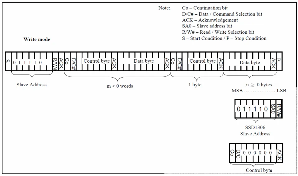
Studying the datasheet and instructions of the SSD1306 is the key to effectively controlling OLED screens. Here we take writing data via the IIC bus as an example to introduce the topic: the write mode timing specified in the SSD1306 datasheet is as follows:
3.1 Send Start Signal
The host first initiates a start (START) signal, which marks the start of communication;
3.2 Transmit Slave Address
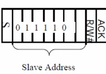
After the start condition, the master needs to send the slave address first. According to the datasheet, the specific process is as follows:
- then send the slave address (7 bits)
- Send a read/write bit (1 bit):
The read-write bit being
1indicates read mode; the read-write bit being0indicates write mode; - After receiving the address, the slave will send out a acknowledge signal (ACK) according to whether the address matches, indicating that it has confirmed the communication request from the master.
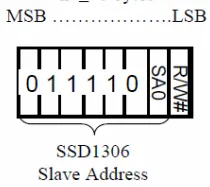
For OLED modules, their slave address is fixed as a 7-bit address, where the upper 6 bits of the address are fixed as 011110, while the 7th bit (the least significant bit) is determined by the hardware pin SA0.
The purpose of this SA0 design is to facilitate mounting two OLED modules on a single I2C bus. When two OLED modules need to be connected, you can adjust the level of the SA0 pin on one of the modules to change its address, thereby avoiding address conflicts.
By default, the manufacturer sets SA0 to 0 (meaning the default address is 0x3C).
- SA0 = 0: The slave address is
0111100, which is 0x3C; - SA0 = 1: The slave address is
0111101, i. e. 0x3D.
Now we can understand why
addr << 1the address needs to be shifted left by one bit?Shifting left by 1 bit is to align the 7-bit slave address to the upper 7 bits, while reserving space for the least significant bit (R/W bit).
3.3 Data Transmission
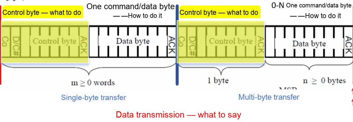
After sending the slave address and receiving the correct acknowledge bit, it is actually equivalent to calling someone's name, and then the slave responds with an "mm-hmm" to indicate that it is ready to receive. Only then does the actual data transmission begin.
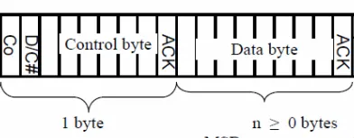
When the ESP32 writes data to a slave OLED screen, the content essentially consists of commands or data that the ESP32 transmits to it. Before sending a single command byte or data byte, or a set of such bytes, a control byte is always required.
- Control Byte —— Defining the Nature of an Event
- Command bytes / data bytes — these specify the exact operation to be performed and how it should be executed
1. Transmission Control Byte
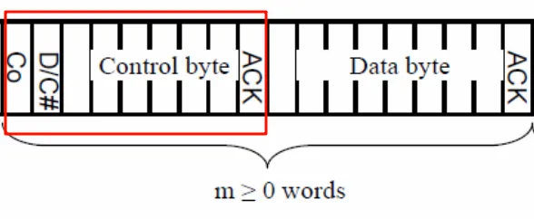
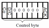
A control byte mainly consists of the Co and D/C# bits followed by six zeros and an acknowledge bit.
After receiving the response signal from the slave, the master will send a control byte to control the subsequent data type of the OLED.
The specific composition structure is as follows:
- Co bit: when set to
0, it indicates that only one data/command byte follows; when set to1, it indicates that multiple consecutive data/command bytes follow. - D/C# bit: When set to
0, it indicates that the transmitted content is a command; when set to1, it indicates that the transmitted content is display data. - Six zeros.
- OLED module acknowledge bit (ACK).
2. Send command bytes or data bytes
The Co bit determines whether to send a single or a group of data/command bytes, and the D/C# bit determines whether to send data bytes or command bytes.
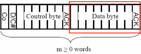
If D/C# = 0, the transmitted content is a command (e. g., clear screen, set display position, etc.); if D/C# = 1, the transmitted content is display data (pixel data). An acknowledge signal (ACK) will be generated after each control byte or data byte is received.
In the Sequence Diagram, a data/command byte is sent first, followed by a group of data/command bytes; of course, all of these are optional.
3.4 Send Stop Signal
Finally, the host sends a stop signal to mark the end of communication.
4. Control by writing instruction codes to the OLED
4.1 OLED Command Table
Before controlling the OLED module, we also need to refer to the command table of the OLED in its datasheet, which defines how to configure display parameters, update content, and implement dynamic effects.
To adjust the screen brightness, a contrast command needs to be sent; to realize text scrolling, the timing configuration of the scrolling command is required. Mastering these commands is the first step to unlocking all functions of the OLED. With this command table, simple codes can precisely control the hardware. Let's take a look at some common commands in the OLED command table.
OLED commands are generally divided into configuration commands and control commands, which together determine how the display effect is achieved.
- Configuration Commands
These commands are used to configure the operating parameters of the OLED, and are typically used during initialization to ensure that the OLED enters the correct operating mode.
Command | Description |
0x81 | Set Contrast (Brightness) |
0xA8 | Set Multiplexing Ratio (Screen Height) |
0xA8 | Set Multiplexing Ratio (Screen Height) |
0xDA | Configure the hardware settings for the COM pins |
0xD5 | Set display clock division ratio |
0xD9 | Set the precharge period |
0xDB | Set VCOMH Selection |
0x8D | Enable/disable the charge pump |
0x20 | Set the addressing mode (horizontal, vertical, page addressing) |
These commands do not directly change the displayed content, but instead affect the operating mode of the OLED.
- Control Commands
These commands are mainly used to dynamically control the display status of the OLED, such as turning the screen on/off, flipping, scrolling, etc. , and they can be called at any time during program operation.
command | Description |
0xAF | Turn on Display |
0xAE | Turn off the display (enter sleep mode) |
0xA4 | Only display data in RAM |
0xA5 | Full Screen Illumination (Test Mode) |
0xA6 | Normal Display Mode |
0xA7 | Inverted Display Mode |
0xA0 / 0xA1 | Flip Horizontal (Left-Right mirror) |
0xC0 / 0xC8 | Flip Vertically (Mirror Top to Bottom) |
0x26 / 0x27 | Horizontal scrolling (left/right) |
0x2F | Start scrolling |
0x00 ~ 0x0F | Low 4-bit column address |
0x10 ~ 0x1F | High 4-bit column address |
0xB0 ~ 0xB7 | Selection Page Address |
These commands can be flexibly invoked during the running of the program, take effect immediately, and affect the content or mode of OLED display.
To sum up:
- Setting commands: used for OLED initialization to determine its operating modes (such as contrast, addressing mode, etc.).
- Control commands: Used to dynamically change the display status of the OLED (such as screen on/off, scrolling, flipping, etc.).
4.2 Actual Code Implementation
After analyzing the datasheet, we can proceed to write the corresponding operation code. Here we will take the example of the ESP32 sending a command/data to an OLED screen for the coding demonstration.
#include <Wire.h>

#define OLED_ADDR 0x3C  // I2C address of the SSD1306

// Send a command to the OLED
void sendCommand(uint8_t cmd) {
  Wire.beginTransmission(OLED_ADDR);
  Wire.write(0x00);  // 0x00 means the following data is a command
  Wire.write(cmd);
  Wire.endTransmission();
}

// Send data to the OLED (used to light up pixels)
void sendData(uint8_t data) {
  Wire.beginTransmission(OLED_ADDR);
  Wire.write(0x40);  // 0x40 means the following data is image data
  Wire.write(data);
  Wire.endTransmission();
}

// Initialize the OLED
void initOLED() {
  sendCommand(0xAE);  // Turn off the display (power-saving mode)
  sendCommand(0xD5);  // Set the clock divider
  sendCommand(0x80);
  sendCommand(0xA8);  // Set the multiplex ratio
  sendCommand(0x3F);  // 64 rows high
  sendCommand(0xD3);  // Display offset
  sendCommand(0x00);
  sendCommand(0x40);  // Set the start line (0x40 = start from line 0)
  sendCommand(0x8D);  // Charge pump setting
  sendCommand(0x14);
  sendCommand(0x20);  // Memory addressing mode
  sendCommand(0x00);  // Horizontal addressing
  sendCommand(0xA1);  // Left-right mirror (default direction)
  sendCommand(0xC8);  // Up-down mirror
  sendCommand(0xDA);  // Set the COM pin configuration
  sendCommand(0x12);
  sendCommand(0x81);  // Set contrast (brightness)
  sendCommand(0x7F);  // 0x00 (dim) to 0xFF (brightest)
  sendCommand(0xD9);  // Pre-charge period
  sendCommand(0xF1);
  sendCommand(0xDB);  // VCOMH voltage
  sendCommand(0x40);
  sendCommand(0xA4);  // Display only the data in RAM
  sendCommand(0xA6);  // Normal display (not inverted)
  sendCommand(0xAF);  // Turn on the display
}

// Light up some pixels ?????? The next section explains why this code is written this way
void drawPixels() {
  sendCommand(0xB0);  // Select page 0 (0~7)
  sendCommand(0x00);  // Set the lower 4 bits of the column (start column)
  sendCommand(0x10);  // Set the upper 4 bits of the column

  for (int i = 0; i < 16; i++) {  // Draw 16 columns of pixels
    sendData(0xFF);  // 0xFF = light up 8 pixels (all white)
  }
}
/*********************************************************************************/
void setup() {
  Wire.begin();
  initOLED();   // Initialize the OLED
  drawPixels(); // Light up the OLED!
}

void loop() {
}
Additionally, how should the code be written if multiple commands/data need to be sent?
// Send multiple commands to the OLED
void sendCommands(const uint8_t *cmds, uint8_t length) {
  Wire.beginTransmission(OLED_ADDR);
  Wire.write(0x00);  // 0x00 means the following data is a command
  for (uint8_t i = 0; i < length; i++) {
    Wire.write(cmds[i]);  // Send the commands in sequence
  }
  Wire.endTransmission();
}

// Send multi-byte data to the OLED (used to display content)
void sendDataBlock(const uint8_t *data, uint8_t length) {
  Wire.beginTransmission(OLED_ADDR);
  Wire.write(0x40);  // 0x40 means the following data is image data
  for (uint8_t i = 0; i < length; i++) {
    Wire.write(data[i]);  // Send the data in sequence
  }
  Wire.endTransmission();
}
5. Summary of This Chapter
This chapter focuses on the I²C communication of OLED screens, and progresses step by step from theory to practice. We first learned about the basic principles of OLED screens and the function of the SSD1306 driver chip, clarified the self-luminous characteristic of each pixel and the application of the I²C interface in actual modules, which provides basic cognition for subsequent data transmission.
Subsequently, by analyzing the I²C write data timing of the SSD1306, we have grasped the communication process: the generation of the start signal, the transmission and acknowledgment of the slave address, the transmission of control bytes and data bytes, and the generation of the stop signal. We particularly emphasized the functions of the Co bit and D/C# bit in the control byte, as well as the transmission logic of data/command bytes, which is equivalent to formally starting the "interaction and command issuing" after completing the "roll call confirmation" with the OLED.
In practical operation, we use the Wire library with ESP32 to send commands and data to the OLED, implementing functions including screen initialization, parameter configuration, and pixel display. Meanwhile, we demonstrate how to send commands or data in batches to efficiently control the display content. Through these exercises, readers can not only master the basic operation methods of OLED display, but also understand the application process of I²C communication in actual device control, laying a solid foundation for subsequent more complex display operations and graphics rendering.