
Contents
1. Introduction
In the previous section, we learned how to use software simulation to implement IIC communication. Simply put, software IIC is equivalent to manually manipulating the SDA and SCL lines step by step via code, and controlling their high and low levels to simulate IIC transmission. Although this method is flexible and adaptable to different pin configurations, it relies on the CPU to execute code for timing control, resulting in a low communication speed. Additionally, it is highly susceptible to interference from interrupts or task scheduling, which leads to unstable data transmission.
However, the ESP32 has a built-in hardware IIC controller. The hardware IIC uses a dedicated hardware unit to handle data transmission, which delivers higher efficiency and stability and frees up the CPU to process other tasks.
To make it easier for developers to use the hardware IIC of the ESP32, the official Arduino team provides the Wire library, which encapsulates common operations such as IIC device initialization and data read/write. This way, we do not need to concern ourselves with the underlying timing, and can easily complete IIC communication just by calling the library functions.
Next, we will learn about the Wire library, and demonstrate through sample code how to use hardware I2C to communicate with peripherals on the ESP32.
2. Wire Library
Wire library is a class library for hardware IIC communication. We will elaborate on it from two parts: classes and objects and common member function to understand the structure and usage of the Wire library.
2.1 Classes and Objects
Wire library centers on the TwoWire class, which handles the low-level operations of the I2C bus. In the Arduino framework, the TwoWire class initializes key parameters via its constructor, such as bus number, pin configuration, buffer size and communication control flags.
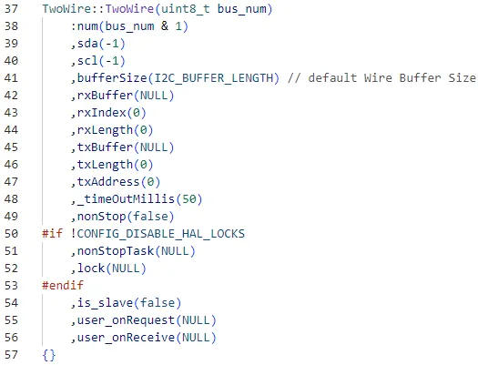
TwoWire::TwoWire(uint8_t bus_num)
    : num(bus_num & 1),     // Bus number (0 or 1)
      sda(-1),              // SDA pin initialized as unassigned
      scl(-1),              // SCL pin initialized as unassigned
      bufferSize(I2C_BUFFER_LENGTH), // Default buffer size
      rxBuffer(NULL),       // Receive buffer pointer
      rxIndex(0),           // Current read position in the receive buffer
      rxLeng th(0),          // Total length of received data
      txBuffer(NULL),       // Transmit buffer pointer
      txLength(0),          // Total length of data to be sent
      txAddress(0),         // I2C address of the target device
      _timeOutMillis(50),   // Communication timeout (50 ms)
      nonStop(false),        // Whether non-continuous communication mode is enabled
      is_slave(false),       // Master/slave mode flag (master mode by default)
      user_onRequest(NULL),  // Callback function for when the master requests data in slave mode
      user_onReceive(NULL)   // Callback function for receiving data in slave mode
{
    // Other initialization code (e.g., multithreading support)
}
The Wire library instantiates two TwoWire objects by default: Wire and Wire1. Among them, Wire corresponds to the I2C0 bus; for example, on the ESP32, it uses pins 21 (SDA) and 22 (SCL) by default. Wire1 is exclusive to the ESP32, corresponds to the I2C1 bus, and uses pins 32 (SDA) and 33 (SCL) by default. These two global objects can be used directly without manual instantiation by the user.
Wire: By default, the IIC0 port (standard IIC) is used.Wire1(ESP32 Exclusive): Uses IIC1 port (the second IIC channel) by default.

TwoWire Wire = TwoWire(0);   // Instantiate the bus 0 object
TwoWire Wire1 = TwoWire(1);  // Instantiate the bus 1 object
2.2 Member Function
1. begin ()- Initialize the I2C bus
Function: Used to initialize the I2C bus, configure the SCL (clock) and SDA (data) pins, and initiate communication.
Syntax:
Wire.begin();
Wire.begin(sda, scl);
Wire.begin(sda, scl, frequency);Parameter:
sda(Optional): SDA pin number (int), default is -1 (use the default pin).scl(optional): SCL pin number (int), which defaults to -1 (use the default pin).frequency(Optional): IIC clock frequency (uint32_t), which defaults to 100000 (100kHz), with optional values including 400000 (400kHz) and so on.
Return value: None.
2. beginTransmission ()- Start IIC transmission
Function: Specify the IIC device address to prepare for data transmission.
Syntax:
Wire.beginTransmission(address);Parameter : address : 7-bit address of the IIC device (uint8_t).
Return value: None.
3. write ()- Send data
Function: Send one or more bytes of data to an IIC device.
Syntax:
Wire.write(value);
Wire.write(buffer, length);Parameter:
value: The single-byte data (uint8_t) to be sent.buffer: The data array to be sent (uint8_t*).length: Data length (size_t).
Return value: Returns the number of bytes sent successfully (size_t).
4. endTransmission ()- End IIC transmission
Function: Complete the current I2C transmission, detect the response status of the slave, and determine whether the communication is successful via the ACK signal.
Syntax:
uint8_t Wire.endTransmission();
uint8_t Wire.endTransmission(bool stop); Parameter:
stop(optional, default istrue):true: Send the stop condition (STOP), fully release the bus, and terminate this communication session.false: Send a Repeated START condition to retain bus control for subsequent operations (e. g., multi-segment continuous transmission).
Return value: Returns the transmission status (uint8_t)
0(Success): All address and data bytes have received the ACK signal from the slave device.1(Data too long): The data to be sent exceeds the I2C buffer limit (e. g., the buffer is only 32 bytes, but an attempt is made to send 40 bytes).2(Address NACK): The slave did not respond to the address (address error, device not connected or not powered on).3(Data NACK): The slave does not acknowledge during data transmission (data format error or register not supported).4(Bus Error): Bus conflict, clock stretching timeout, or physical connection failure.
5. requestFrom ()- Read data request
Function: Request to read data from an IIC device.
Syntax:
Wire.requestFrom(address, quantity);
Wire.requestFrom(address, quantity, stop);Parameter:
address: 7-bit address of the IIC device (uint8_t).quantity: Number of bytes to be read (uint8_t).stop(optional): whether to send a stop signal (bool), the default value istrue, which means the bus is released after data request;falsemeans the bus is not released.
Return value: Returns the actual number of bytes read (uint8_t).
6. available ()- Check available data
Function: Returns the number of bytes available for reading in the current IIC buffer.
Syntax:
Wire.available();Parameters: None.
Return value: Returns the number of bytes available in the buffer (int).
7. read ()- Read data
Function: Read one byte of data from an IIC device.
Syntax:
Wire.read();Parameters: None.
Return value: Returns the byte data (int) that has been read.
8. setClock ()- Set the IIC frequency
Function: Dynamically adjust the IIC clock frequency.
Syntax:
Wire.setClock(frequency);Parameter: frequency: IIC clock frequency (uint32_t), in Hz, e. g. 100000 (100kHz), 400000 (400kHz).
Return Value: None.
9. onReceive () - Set receive interrupt callback
Function: Set a callback function that will be triggered when the IIC device receives data.
Syntax:
Wire.onReceive(handler);Parameters: handler: callback function, defined in the format void handler (int numBytes), numBytes indicates the number of bytes received.
Return Value: None.
10. onRequest ()- Set request interrupt callback
Function: Set a callback function, which is triggered when the IIC master requests data (used when the ESP32 works in slave mode).
Syntax:
Wire.onRequest(handler);Parameter: handler: callback function, defined in the format void handler (), which is invoked when the host requests data.
Return Value: None.
3. Practical Operation Cases of Hardware IIC
3.1 Hardware IIC: Simple Communication Between ESP32 and OLED Module
In the previous section, we implemented simple communication between the ESP32 and the OLED module using software I²C, which can simulate timing and receive acknowledge bits by manually controlling the SDA and SCL pins. Now, we will use the hardware I²C function of the ESP32 to realize the same communication.
#include <Wire.h>

// Define the SDA and SCL pins
#define SDA_PIN 21
#define SCL_PIN 22

void setup() {
  Serial.begin(115200);  // Initialize serial

  // Initialize the hardware I2C bus using custom SDA and SCL pins
  Wire.begin(SDA_PIN, SCL_PIN);

  Serial.println("I2C Initialized");

  // Check device response
  Wire.beginTransmission(0x3C);  // Assume the OLED address is 0x3C
  uint8_t ack = Wire.endTransmission();  // End communication and return the ACK status

  if (ack == 0)
  {
    Serial.println("ACK received");
  }
  else
  {
    Serial.println("No ACK");
  }
}

void loop() {
  // Other communication logic or device interaction can be added here
  delay(1000);  // Delay so the output can be observed
}
3.2 IIC Scanner
The ESP32 successfully obtained the ACK (acknowledgment) signal by sending a specific I²C address to the OLED module, which verifies that the device is in a normal working state.
Then, by extending this logic to similar cases, if we sequentially send requests to all possible addresses on the I²C bus, we can detect all connected devices, and with just a few more lines of code, we can even obtain the corresponding address information.
In I²C communication, although the data bus performs 8-bit transmission, the address field of the device is actually 7 bits long, and the last 1 bit is used to indicate a read/write operation.
Therefore, the I²C scanner operates precisely on this principle — it iterates through all possible 7-bit I²C device addresses (0x08 to 0x77, i. e., 8 to 119) and monitors for the presence of ACK signals to identify which devices are communicating on the bus.
An I²C scanner is an extremely practical tool that helps us quickly identify the addresses of I²C devices and determine their operating status during debugging and development. For example, if we fail to scan the address of a certain device, it indicates that the device may not be connected properly, has abnormal power supply, or the I²C wiring sequence is reversed.
Here is a code example for making an I²C scanner with the ESP32:
#include <Wire.h>

void setup()
{
  Serial.begin(115200);
  Wire.begin(21,22);
}

void loop()
{
  byte error, address;
  int nDevices;
  Serial.println("Scanning...");
  nDevices = 0;
  for(address = 1; address < 127; address++ )
  {
    Wire.beginTransmission(address);
    error = Wire.endTransmission();
    if (error == 0)
    {
      Serial.print("I2C device found at address 0x");
      if (address<16)
        Serial.print("0");
      Serial.print(address,HEX);
      Serial.println("  !");
      nDevices++;
    }
    else if (error==4)
    {
      Serial.print("Unknown error at address 0x");
      if (address<16)
        Serial.print("0");
      Serial.println(address,HEX);
    }
  }
  if (nDevices == 0)
    Serial.println("No I2C devices found\n");
  else
    Serial.println("done\n");
  delay(5000);
}
This code implements an ESP32 I²C device scanner, whose main function is to detect all device addresses on the I²C bus and print the responding device addresses in the serial monitor. This is extremely important for the debugging and development of I²C devices, as it helps developers confirm whether the I²C device is connected properly and whether the address meets expectations.
The execution logic of the program is as follows: First, in the setup () function, the ESP32 initializes the I²C bus via Wire.begin (21,22);, specifying GPIO21 as SDA (data line) and GPIO22 as SCL (clock line). Meanwhile, it initializes serial communication via Serial.begin (115200);so that the scan results can be viewed in the serial monitor.
After entering the loop (), the program iterates through the valid address range (1 ~ 126) of I²C in sequence, and uses Wire.beginTransmission (address);to send a data frame to attempt communication with the device. It then calls Wire.endTransmission ();to check whether the device returns an ACK (acknowledge signal).If the device responds correctly (error == 0), it indicates that an I²C device exists at this address, and the program will display the device address in hexadecimal format on the serial monitor. If error == 4, it means an unknown error has occurred, which may be caused by poor contact of the I²C lines or device abnormality, and the program will print the error address.
After traversing all possible device addresses, the program counts the number of detected devices. If nDevices == 0, it indicates that no I²C device is detected, which may be caused by unconnected or faulty I²C devices, or reversed SDA/SCL lines. If devices are found, the program prints "done" to prompt that the scan is completed. To continuously monitor device status, the program will rescans every 5 seconds to ensure that newly added or disconnected I²C devices can be discovered dynamically.
With this I²C scanner, developers can quickly determine whether an I²C device is functioning properly and obtain its communication address, making it a highly useful tool during the debugging and development process of I²C devices.
4. Summary of This Chapter
This chapter compares software I²C and hardware I²C to help you understand the advantages and usage of ESP32 hardware I²C. Compared with software simulation, hardware I²C uses a dedicated hardware unit to control the timing, which is not only faster and more stable, but also reduces the burden on the CPU, making it suitable for actual development scenarios.
We have studied the usage of the Wire library in detail, including bus initialization (begin ()), data reading and writing (beginTransmission (), write (), endTransmission (), requestFrom ()), available data check and reading (available (), read ()), as well as clock configuration (setClock ()) and interrupt callbacks (onReceive (), onRequest ()) and other commonly used functions.With these functions, we can conveniently implement I²C communication without manually controlling the levels of SDA and SCL.
Finally, through the communication example between ESP32 and OLED display as well as the I²C scanner program, we verified the existence and address information of the device, and meanwhile mastered how to quickly debug the I²C bus. These operations not only consolidate the application method of hardware I²C, but also lay a foundation for connecting more I²C peripherals and realizing complex data interaction in the follow-up.