
Contents
1. Introduction
Have you ever come across the on radios, the volume regulators on speakers, or even the control on some industrial machines? They may look like just ordinary rotatable , but in fact, they work with a rotary encoder to convert the physical rotation movement into electrical signals, so that the ESP32 can tell: how many steps the has turned, and whether the direction is clockwise or counterclockwise.
In this section, we will use the KY-040 rotary encoder module to conduct an experiment, learn its working principle, and read the rotation signals via the external interrupt function of the ESP32.
2. Basics of Encoder
Before using the KY-040 rotary encoder module, we first need to clarify what an "encoder" actually is. Only by understanding its basic working principle and classification can we better grasp why the ESP32 can use it to determine the rotation direction and step count of the .
Next, let's first take a look at what an encoder is and what its common types are.
2.1 What is an Encoder
An encoder is a type of sensor that converts mechanical motion (rotary or linear motion) into digital or electrical signals. When the on it is turned, the encoder outputs a series of pulse signals; by reading these signals, the ESP32 can detect how many steps the has rotated as well as the direction of rotation.
In electronic devices, encoders are commonly used for:
- Volume Adjustment
- Angle detection of robotic arm;
- Displacement measurement of CNC machine tools;
- input for smart home appliances.
Simply put: an encoder converts rotational motion into electrical signals, and then into data that the ESP32 can recognize.
2.2 Common Classifications of Encoders
Encoders can be divided into multiple types according to their different output signals, and common classification methods mainly include incremental encoders and absolute encoders. There are significant differences among different types of encoders in terms of output characteristics, application scenarios and accuracy requirements. Learning the principles and features of these two types of encoders helps to select appropriate devices according to actual needs in specific design.
2.2.1 Incremental Encoder
An incremental encoder is a type of rotary position measurement device that is widely used. It continuously outputs pulse signals related to angle changes during rotation, thereby enabling the detection of angle, rotational speed and displacement. Its operating principle is similar to that of a "pedometer": it does not directly provide the absolute position, but obtains relative displacement information by accumulating the number of pulses.
- The output pulse signal records the "relative displacement".
- The ESP32 needs to count to obtain how many steps the has rotated.
His main characteristics are as follows:
- Simple in structure and low in cost, it is suitable for large-scale applications.
- The output is in the form of relative position, which requires an external circuit to perform cumulative counting to obtain the actual position.
- Flexible resolution, depending on the number of graduations on the code disc.
- sensitive to power loss; once the power is cut off, the accumulated position will be lost, and a reset or reference point calibration is required.
The KY-040 we use in this chapter falls into the category of incremental rotary encoders.
2.2.2 Absolute Encoder
An absolute encoder is a type of position sensor that can directly output a "unique code corresponding to the current position". Unlike incremental encoders, an absolute encoder does not need to calculate displacement by accumulating pulses; instead, it can directly read the absolute position of the shaft at any moment. This feature allows it to accurately restore the current position even after a power outage or system restart, eliminating the risk of losing the reference point.
- It outputs an "absolute position" signal.
- You can directly know the angle of the without a counter.
The main features of absolute encoders include:
- Absolute positioning: Each position corresponds to a unique code, and the reading does not depend on the movement process.
- Power-off retention: Even if the system is powered off, the current position encoding remains valid, and there is no need to recalibrate the zero point.
- High resolution: Higher accuracy can be achieved by increasing the number of tracks on the code disc.
- High cost: Compared with incremental encoders, it features a more complex structure and higher manufacturing cost.
2.3 Working Principle of Incremental Encoder
An incremental encoder is a rotary position sensor that outputs relative displacement information. It generates electrical signals through mechanical rotation, which can be used by a microcontroller to calculate the direction and number of steps a has turned. Understanding the signal characteristics and counting methods of incremental encoders will facilitate subsequent reading of data from the KY-040 rotary encoder with the ESP32.
2.3.1 Basic Structure
First, let's understand the basic structure of an encoder and learn how mechanical rotation is converted into electrical signals, so as to avoid the confusion of "why no signal is read" or "the direction is reversed" in subsequent experiments.
A typical encoder consists of an optical code disc, a photodetector, and a signal processing circuit. When the or shaft rotates, the engraved lines on the code disc periodically block the optical path, and the photodetector converts the optical signal into a pulsed electrical signal, outputting two square waves staggered by 90°, which are respectively Phase A and Phase B. The working steps are as follows:
- The transparent and opaque graduations on the code disc periodically block the optical path;
- The photodetector converts the optical signal into a pulsed electrical signal;
- The signal processing circuit outputs two channels of square waves.
2.3.2 Signal Characteristics
The two square waves output by the signal processing circuit are respectively referred to as Phase A and Phase B. Now, can you imagine why two signals are needed?
If there is only one pulse signal, the microcontroller can only know how many steps the has turned, but cannot determine the rotation direction. By outputting two channels of A/B square waves staggered by 90°, the rotation direction can be derived from the phase relationship:
- Phase A leads Phase B → Clockwise
- Phase B leads Phase A → Counterclockwise
In addition, the number of graduations per revolution is fixed, and each graduation corresponds to one pulse. By accumulating pulses, the microcontroller can calculate the relative displacement of the ; combined with the phase relationship, the rotation direction can be obtained; by counting pulses within a unit time, the rotation speed can also be estimated. For example, the KY-040 has 20 graduations per revolution and outputs one pulse for every 18° of rotation.



The relative sequence of A/B phases (which one transitions first) → determines the direction
Pulse count → determines the number of rotation steps
To summarize: The signals of Phase A and Phase B have the following characteristics:
- The number of pulses in phase A and phase B is proportional to the rotation angle.
- The phase difference between phase A and phase B can be used to determine the rotation direction.
- By counting the number of pulses, the relative displacement of the rotation can be obtained.
2.4 Working Principle of Absolute Encoder
When we introduced the incremental encoder earlier, we saw that it outputs a series of pulse signals, and determines the position and direction based on the number of pulses and the phase difference. However, if the system suddenly loses power, the incremental encoder will "forget" its stopped position when powered on again, and must be recalibrated via an additional reference point. This is unacceptable in many high-precision scenarios, such as tool positioning of CNC machine tools or angle detection of robotic arm joints. To solve this "memory loss" problem, the absolute encoder came into being.
In terms of operating principle, absolute encoders typically adopt optical code discs or magnetic code discs, on the surface of which specific coding patterns are engraved. When the rotating shaft is at different angular positions, the light transmission or magnetic distribution of the code disc forms a unique set of digital signals (commonly binary code or Gray code), which are output after being read by a photoelectric or magnetoelectric sensor. The control system can obtain the corresponding angle or position value by analyzing this set of codes.
2.4.1 Working Principle
An absolute encoder has special encoding tracks (usually in binary, Gray code or other encoding formats) engraved on its encoding disc.
- Each angular position corresponds to a unique set of code combinations.
- By reading the light-transmitting/non-light-transmitting (or magnetic pole) states of different tracks on the encoding disc via a photoelectric sensor or a magnetic sensor, a string of parallel digital signals can be obtained.
- This set of signals serves as the "ID number" of the current position: it is unique and will not be lost even when the power is cut off.
Therefore, an absolute encoder can immediately tell you "which degree I am at right now" as soon as it is powered on, with no need for an additional reference point.
2.4.2 Principle of Single-turn and Multi-turn
Absolute encoders are further classified according to their measurement range as follows:
- Single-turn absolute encoder: The code disc only covers 360°, and the encoding result only represents the position within the current rotation.
- Multi-turn absolute encoder: Based on the single-turn design, it is equipped with an additional gear train or energy storage mechanism, which can record the total number of rotations. This allows it to obtain not only the current angle but also the total number of turns that have been completed.
2.4.3 Example of Encoding Method
Common encoding methods include:
- Binary encoding: It directly represents angles in binary form, which is simple and intuitive, but carries the risk of misjudgment caused by multiple bits flipping simultaneously.
- Gray Code: Only one bit changes between adjacent angles, which reduces errors caused by signal jitter, so it is widely used in industrial encoders.
Example: For an 8-bit Gray code absolute encoder, it can provide 2^8 = 256 distinct positions within one revolution, which means the accuracy is 360° / 256 ≈ 1.4°.
2.5 Selection of Encoders in Practical Applications
In practical engineering applications, selecting an appropriate encoder is often more critical than understanding its operating principle. Each type of encoder has its own advantages and limitations, so the choice must be determined based on the specific application scenario. For example, in situations where rotational speed and relative position need to be detected, incremental encoders are widely used due to their simple structure, low cost, and convenient signal processing; they are suitable for being mounted on motor shafts to achieve speed feedback or position control. However, their drawback is that once the system loses power or encounters interference, the zero position will be lost, and a reset or homing operation is required when the system is powered back on.
In contrast, absolute encoders can provide the true position of the shaft at any moment, and will not lose data even when restarted after a power failure. This feature makes it particularly important in scenarios requiring high precision and high reliability, such as CNC machine tools, robot joint control, and medical equipment. Although absolute encoders are relatively expensive and their interfaces and data processing are also relatively complex, they can significantly reduce debugging and maintenance costs in critical equipment.
3. KY-040 Rotary Encoder
After learning the basic concepts and classification of encoders, we can use a common entry-level module KY-040 Rotary Encoder to deepen our understanding. It is one of the most classic components for learning incremental encoders. By analyzing its internal core components, pin definitions and working logic, we can master the usage of rotary encoders more intuitively.
3.1 Core Components
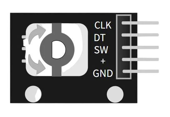
At the core of the KY-040 is an incremental rotary encoder, which essentially consists of a set of mechanical contacts and a dial. As the internal metal sheet rotates with the , it sequentially contacts different pins, thereby generating pulse signals.
- CLK (Phase A) and DT (Phase B): Output two square-wave signals with a phase difference of 90°. The rotation direction of the can be determined by detecting the sequence of their changes.
- SW (Button): The itself can be pressed down to serve as an independent mechanical switch input. This design enables the KY-040 to not only detect angle changes, but also function as an interactive controller with a button.
It should be noted that although the CLK pin of a rotary encoder is named "Clock", it does not provide a precise time reference like the clock of a microcontroller, but is merely a signal used to determine the rotation sequence.
Here, CLK and DT are merely two signal lines that generate pulses as the component rotates; their high-low transitions can be detected, but they do not serve as a clock source themselves.
3.2 Schematic Diagram and Module Pins
The KY-040 module incorporates two internal pull-up resistors that pull the CLK and DT pins up to VCC. Among them, the internal pull-up resistors: CLK/DT are pulled up by default, so no external resistors are required.
Turn the and press the button. When pressed, the button connects the SW pin to the GND pin.
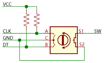
Encoder pins | Function Description |
CLK (Phase A) | Rotary Pulse Output |
DT (Phase B) | Auxiliary pulse output, used for direction judgment |
SW (push button) | It is grounded when pressed, disconnected when released, and remains in a floating state. |
VCC | positive electrode of power supply |
GND | Power Ground |
3.3 Working Logic
The rotary encoder provides two interaction modes:
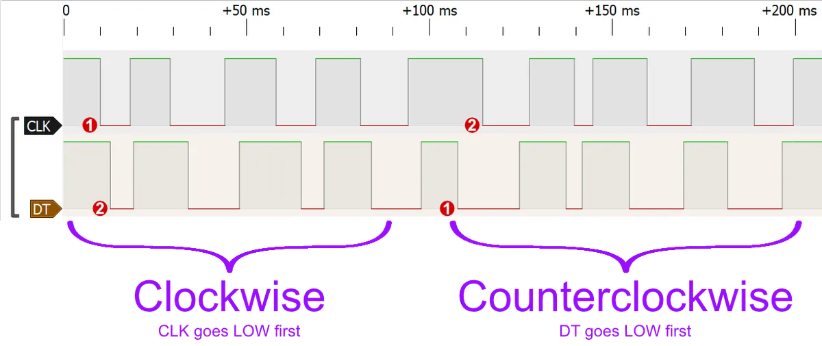
- Rotation - You can rotate the by clicking the arrows: the upper arrow rotates it one step clockwise, and the lower arrow rotates it one step counterclockwise. Rotating the will generate digital signals on the DT and CLK pins, which will be explained below.
- Button - Click the to press the button. When pressed, the button connects the SW pin to the GND pin.
4. Rotation Counting Experiment —— External Interrupt Application
4.1 Hardware Connection
Encoder pins | Function Description | ESP32 Connection | Pin Type | Whether an external interrupt is required |
CLK (Phase A) | Rotary Pulse Output | Connect to any GPIO (e. g. GPIO18) | Numeric Input | It is necessary to capture pulses using interrupts |
DT (Phase B) | Auxiliary pulse output, used for direction judgment | Connect to any GPIO (e. g. GPIO19) | Numeric Input | Must use the interrupt capture direction |
SW (push button) | It is grounded when pressed, disconnected when released, and remains in a floating state. | Connect to GPIO21 (configured as INPUT_PULLUP) | Numeric Input | not mandatory |
VCC | positive electrode of power supply | Connect to ESP32 3.3V | Power Supply | not mandatory |
GND | Power Ground | Connect to ESP32 GND | Power Supply | not mandatory |
4.2 Software Implementation Steps (Interrupt Trigger → AB Phase Judgment → Counting Variable Change)
When using the KY-040 encoder with ESP32 or Arduino, the core workflow of the software implementation generally consists of the following steps:
- Initialization and Pin Configuration
Configure CLK (Phase A) and DT (Phase B) as input mode, and the CLK pin is typically set as an external interrupt trigger source. In this way, the pulse changes generated during rotation can trigger an interrupt immediately.
#define CLK_PIN 18   // Phase A
#define DT_PIN  19   // Phase B
#define SW_PIN  21   // Button

volatile int counter = 0;      // Rotation count
volatile bool rotated = false; // Flag indicating whether rotation occurred

void setup() {
  Serial.begin(115200);

  pinMode(CLK_PIN, INPUT);
  pinMode(DT_PIN, INPUT);
  pinMode(SW_PIN, INPUT_PULLUP);
}- Interrupt Trigger
Whenever a CLK signal transitions (usually on the falling edge), the interrupt service function is triggered.
  // Attach external interrupt (falling-edge triggered)
attachInterrupt(digitalPinToInterrupt(CLK_PIN), handleEncoder, FALLING);- Determine the direction and update the count
In the interrupt function, the rotation direction is determined by reading the level of DT (phase B). If the level of DT maintains a certain phase relationship with the change of CLK, it is determined to be clockwise; if the opposite, it is counterclockwise. This is because phase A and phase B always maintain a phase difference of 90°.
In this example, Phase A (CLK) is configured to be triggered by a falling-edge interrupt. Whenever a falling edge occurs on Phase A, the program enters the interrupt and immediately "simultaneously samples" the levels of both Phase A and Phase B. The direction judgment rules are as follows:
If the level states of phase B and phase A are the same → it indicates that phase B transitions earlier than phase A, which corresponds to the clockwise direction, and the count is incremented by 1; if the level states of phase B and phase A are different → it indicates that phase B transitions later than phase A, which corresponds to the counterclockwise direction, and the count is decremented by 1.
Update the counter variable based on the direction judgment result: clockwise → counter + 1; counterclockwise → counter -1.
// Interrupt callback function
void IRAM_ATTR handleEncoder() {
  int clkState = digitalRead(CLK_PIN);
  int dtState  = digitalRead(DT_PIN);

  // Determine direction
  if (clkState == dtState) {
    counter++;  // Clockwise
  } else {
    counter--;  // Counterclockwise
  }
  rotated = true;
}- Button Function (Optional)
If you need to use the SW key, you can additionally configure it as INPUT_PULLUP, and detect level changes in the loop () for menu selection or function switching.
if (digitalRead(SW_PIN) == LOW) {
Serial.println("按钮被按下!");
delay(200); // Debounce
}- Read the encoder measurement results in the main loop
// Output rotation result
if (rotated) {
rotated = false;
Serial.print("旋转计数值: ");
Serial.println(counter);
}
4.3 Overall Implementation Demonstration
18-1 KY-040 Rotary Encoder Signal Reading - Wokwi ESP32, STM32, Arduino Simulator
#define CLK_PIN 18   // Phase A
#define DT_PIN  19   // Phase B
#define SW_PIN  21   // Button

volatile int counter = 0;   // Rotation count
volatile bool rotated = false; // Flag indicating whether rotation occurred

// Interrupt callback function
void IRAM_ATTR handleEncoder() {
  int clkState = digitalRead(CLK_PIN);
  int dtState  = digitalRead(DT_PIN);

  // Determine direction
  if (clkState == dtState) {
    counter++;  // Clockwise
  } else {
    counter--;  // Counterclockwise
  }
  rotated = true;
}

void setup() {
  Serial.begin(115200);

  pinMode(CLK_PIN, INPUT);
  pinMode(DT_PIN, INPUT);
  pinMode(SW_PIN, INPUT_PULLUP);

  // Attach external interrupt (falling-edge triggered)
  attachInterrupt(digitalPinToInterrupt(CLK_PIN), handleEncoder, FALLING);
}

void loop() {
  // Output rotation result
  if (rotated) {
    rotated = false;
    Serial.print("旋转计数值: ");
    Serial.println(counter);
  }

  // Detect button
  if (digitalRead(SW_PIN) == LOW) {
    Serial.println("按钮被按下!");
    delay(200); // Debounce
  }
}
5. Summary of This Chapter
In this chapter, we conducted an experiment with the KY-040 rotary encoder to fully experience the practical application of ESP32 external interrupts.
First, we learned about the basic concept and classification of encoders: Incremental encoders output two channels of pulse signals with a 90° phase difference (Channel A and Channel B), allowing the controller to count pulses to obtain the number of rotation steps and rotation direction;Absolute encoders directly output a unique code corresponding to the current position, and the position information will not be lost even after a power outage, so they are commonly used in high-precision equipment.
Subsequently, we took the KY-040 module as an example to get familiar with its core components and pin functions:
- CLK (Phase A) and DT (Phase B): output two channels of square wave signals with a phase difference of 90°, which are used for counting and direction judgment;
- SW Button: The itself can be pressed to function as an independent button input;
- VCC and GND: Supply power to the module.
In the experimental section, we focused on learning the method of the ESP32 reading rotation signals via external interrupts:
- Configure the CLK pin to trigger a falling-edge interrupt;
- Whenever an interrupt is triggered by CLK, the two levels A and B are sampled simultaneously;
- Determine the rotation direction based on the phase relationship between phase A and phase B:
- When the levels of A and B are the same → clockwise, count + 1;
- When the levels of A and B differ → counterclockwise, count -1;
- In the
loop ()main loop, output the rotation count value and simultaneously detect the status of the SW button.
Through this experiment, we not only mastered the working principle of the rotary encoder, but also learned how to use external interrupts on the ESP32 to realize real-time signal acquisition.