
1. Introduction
In embedded programming, we often face the requirement of quickly responding to external events at specific moments. For example, when a button is pressed, we expect to immediately perform a certain operation, such as turning on an LED. The traditional approach is to constantly check the button state through polling, but this method is not only inefficient, but also may cause us to miss other tasks that require timely processing.
Another common approach is to use delay () for scheduled tasks, such as collecting sensor data at regular intervals. While this may seem to implement periodic tasks, delay () will cause the CPU to completely stall during the waiting period, making it unable to handle other tasks simultaneously.
To address these issues, external interrupts and timers provide a more efficient solution. External interrupts allow us to immediately suspend the current task to handle the corresponding event when an external event occurs, while timers can trigger operations at a preset time, ensuring the CPU does not get stuck and thus can process other tasks in parallel. Through these two mechanisms, embedded systems can handle complex real-time tasks more flexibly and efficiently.
2. Interrupt
2.1 Interrupt Mechanism
Interrupt is a mechanism: when a certain event occurs (triggered by hardware or software), the CPU will suspend the current task and execute a dedicated processing function — Interrupt Service Routine (ISR), and then return to the original task after the processing is completed.
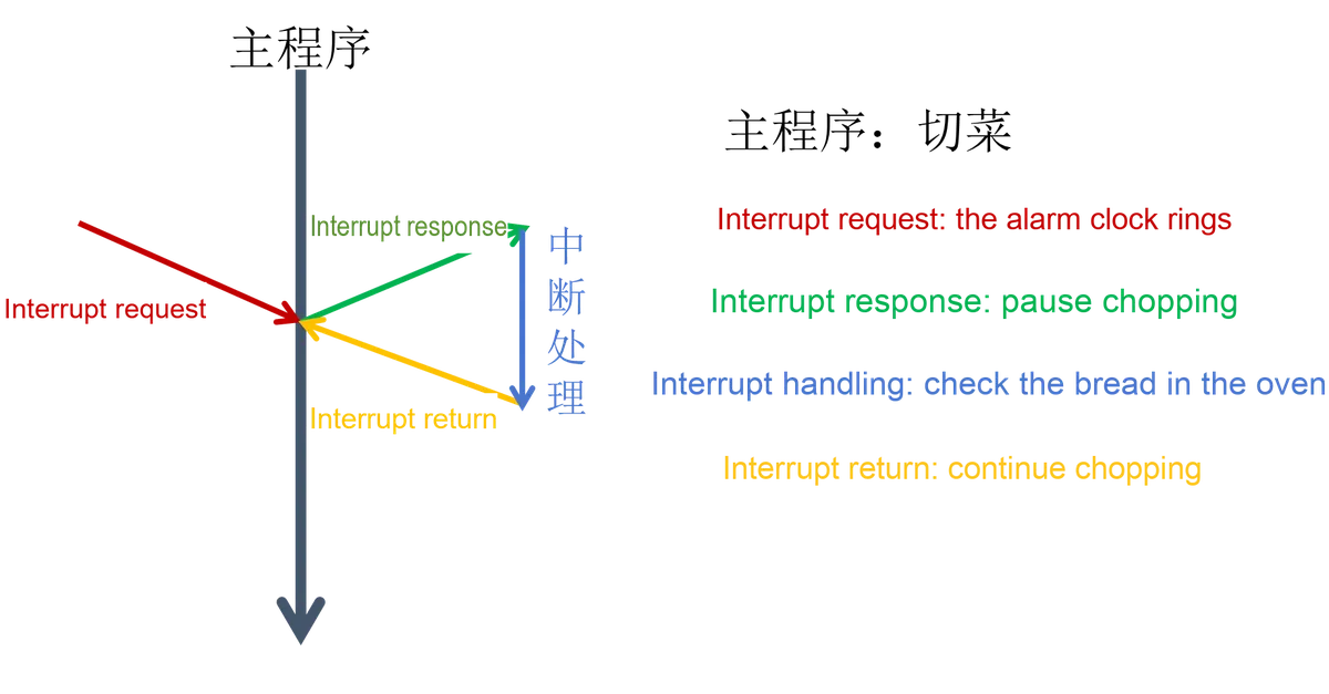
2.2 Basic Concepts of Interrupts
Interrupt source: the source of the event that triggers an interrupt, such as a level change on an external pin (button), timer overflow, incoming serial port data, etc.
Interrupt Service Routine (ISR): Also known as interrupt handling, it is the function executed when an interrupt occurs, usually consisting of brief processing logic such as updating a variable or setting a flag bit.
Interrupt return: After the interrupt handling is completed, the CPU will automatically return to the original code before the interrupt and continue execution.
3. External Interrupt
3.1 Concept and Functions of External Interrupts
In embedded systems, external interrupt is one of the most commonly used types of interrupts. Triggered directly by peripherals or external signals, it enables the CPU to respond immediately without having to rely on continuous polling in a loop program.
Take common applications as an example:
- When the key is pressed, an interrupt is triggered immediately to turn on or toggle the LED.
- When the sensor detects an obstacle, it immediately sends out an interrupt signal to control the car to make an emergency stop.
Compared with the traditional polling method, external interrupts can significantly reduce CPU resource wastage and ensure that critical events are not missed. Therefore, it is not only one of the basic application scenarios of the ESP32 interrupt mechanism, but also an important entry point for embedded programming beginners to understand the working principle of interrupts.
3.2 Interrupt Trigger Mode
The external interrupts of the ESP32 can be triggered according to the change pattern of the pin level. In other words, when a specific change occurs to the pin level, the ESP32 will immediately pause the program being executed and run the interrupt handling function we have written in advance.
This change mode mainly falls into two categories: level triggering and edge triggering. Level triggering makes judgments based on "the pin being kept high or low", while edge triggering makes judgments based on "the moment when the level transitions from high to low or from low to high".
We need to select an appropriate trigger mode according to the application scenario, so that the ESP32 can respond to external events at the right time.
The external interrupts of the ESP32 can be divided into different trigger modes according to the change mode of the pin level, and the common interrupt trigger modes are shown in the following table:
Trigger Mode | Description | Typical Application Scenarios |
|---|---|---|
rising-edge triggered | An interrupt is triggered when the GPIO level transitions from low to high. | Key release detection, signal rising edge capture |
Falling Edge Triggered | An interrupt is triggered when the GPIO level transitions from high to low. | Key press detection, pulse falling edge capture |
dual-edge trigger | An interrupt is triggered when the GPIO level changes (low ↔ high) | Key status monitoring, counting pulse signal |
High-level triggering | Interrupts are continuously triggered when the GPIO remains at a high level. | Detection of external module "ready" signal and duration condition |
low-level trigger | Interrupt is continuously triggered when the GPIO remains at a low level | Fault alarm signal and peripheral "busy" detection |
Here are some additional usage tips for you:
- For instantaneous events (such as key presses and pulse inputs), it is recommended to use edge triggering.
- For status signals that require continuous monitoring, you can use level-triggered mode, but it must be properly handled in the callback to avoid interrupts occupying the CPU completely.
- When jitter occurs in inputs such as mechanical buttons and relays, it is recommended to add hardware filtering or software debouncing, otherwise multiple interrupts may be triggered.
3.3 External Interrupt Core Function
3.3.1 attachInterrupt ()—— Register an external interrupt
Now let's first learn about the interrupt registration function —— attachInterrupt ().
Function purpose: attachInterrupt () is designed to enable the microcontroller to automatically call the specified interrupt function when it detects that a certain pin meets the set trigger condition. It avoids frequent loop () polling and improves response speed and efficiency.
Function prototype:
attachInterrupt(uint8_t interruptNum, void (*ISR)(void), int mode);Parameter Description:
Parameters | Description |
pin | The GPIO pin number to be configured as an interrupt. On ESP32, you need to use |
ISR | The function to be executed when an interrupt is triggered (i. e., the interrupt service routine). This function cannot take parameters nor have a return value. For example:
|
mode | refers to the condition that triggers an interrupt. The optional values are: |
Return value:
- This function has no return value (
void).
Example:
Call setup () to invoke attachInterrupt () to bind the pin, callback function and trigger mode.
attachInterrupt(digitalPinToInterrupt(BUTTON_PIN), handleInterrupt, FALLING);3.3.2 ISR Interrupt Service Routine —— A function that responds to interrupts
When an interrupt event occurs, the CPU will pause the current main program and instead execute a function dedicated to handling this event, which we call the interrupt service routine (ISR), also known as the interrupt handling function.
To define an ISR function, it is recommended to use the following format:
void IRAM_ATTR Ext_INT1_ISR()
{
    // Your Code...
}
Use the IRAM_ATTR attribute to place this code segment in internal RAM instead of flash memory. This way, it executes much faster, enabling extremely fast context switching and interrupt servicing.
Of course, the basic functionality can also be achieved without this identifier, it will just be a bit slower.
void Ext_INT1_ISR()
{
    // Your Code...
}
When writing Interrupt Service Routines (ISRs), special attention should also be paid to the following points:
- The ISR must be brief
- The interrupt service function should be as concise as possible, and avoid executing complex logic or time-consuming operations.
- A common practice is to only set a flag in the ISR, and then
loop ()to handle subsequent tasks based on that flag.
- Avoid blocking operations
- Do not use blocking
delay ()orSerial.print ()functions such as those in ISRs, otherwise it will affect the real-time response of the system and even lead to deadlock.
- Do not use blocking
- Variable Declaration Specification
- Global variables modified in an ISR must be declared with the
volatilekeyword to prevent data inconsistency or logic errors caused by compiler optimizations.
- Global variables modified in an ISR must be declared with the
Why do variables in ISRs need to be declared with volatile?
In C/C++, the compiler will "smartly" optimize the code. If it determines that a variable does not change within the loop () function, it may store the value of this variable in a register for repeated use, instead of reading it from memory every time.
But the problem is this:
- An interrupt service routine (ISR) may modify this variable at any time;
- If the variable is not
volatile, the main loop may keep reading the old value without ever knowing that the ISR has modified it.
👉 Solution: For global variables that will be modified in an ISR, the volatile keyword must be added. This ensures that the compiler will always fetch the latest value directly from memory, keeping data consistent between interrupts and the main loop.
3.3.3 detachInterrupt ()—— Cancel external interrupt
Now let's learn how to cancel an interrupt — detachInterrupt ().
Function: detachInterrupt () is used to disable the external interrupt of the specified pin so that it will no longer trigger the interrupt service function. It is commonly used in scenarios where a certain interrupt needs to be temporarily masked during program operation.
function prototype:
void detachInterrupt(uint8_t interruptNum);Parameter Description:
Parameters | Description |
interruptNum | The pin number of the interrupt to be canceled. On ESP32, digitalPinToInterrupt (GPIO_pin) shall also be used |
Return value:
- This function has no return value (void).
Example:
detachInterrupt(digitalPinToInterrupt(BUTTON_PIN));This line of code will cause the BUTTON_PIN pin to no longer trigger an interrupt.
3.3.4 digitalPinToInterrupt ()—— Obtain Interrupt Number
Function: digitalPinToInterrupt () is used to convert a GPIO pin number to the corresponding interrupt number, which is a required parameter for attachInterrupt () and detachInterrupt ().
function prototype:
int digitalPinToInterrupt(uint8_t pin);Parameter Description:
Parameters | Description |
pin | GPIO pin number, e. g. BUTTON_PIN. |
Return value:
- Returns the interrupt number (int) corresponding to this pin.
- If this pin does not support interrupts, it may return a negative number (e. g., -1).
Example:
attachInterrupt(digitalPinToInterrupt(BUTTON_PIN), handleInterrupt, FALLING);Here, digitalPinToInterrupt (BUTTON_PIN) will return the corresponding interrupt number.
3.3.5 Correlations between Various Functions
Earlier, we introduced several core functions for external interrupts:
digitalPinToInterrupt ()—— Convert the GPIO pin number to the corresponding interrupt number;attachInterrupt ()—— Registers an interrupt, and associates a pin, trigger condition, and ISR with it;ISR (Interrupt Service Routine)—— a function that is automatically executed when an interrupt event occurs;detachInterrupt ()—— Cancels the interrupt so that the pin no longer triggers the ISR.
The relationship and execution process between them can be summarized as follows:
- Identify the pin → Obtain the interrupt number Use
digitalPinToInterrupt (pin)to convert the GPIO pin number to the corresponding interrupt number. - Register an interrupt by using
attachInterrupt (interrupt number, ISR function, trigger mode)to bind this pin to the ISR. - Interrupt Triggered → Execute ISR
When the pin voltage meets the trigger condition (e. g., falling edge), the CPU will suspend the current program and call the ISR immediately. - The main program continues to execute
After the ISR ends, the CPU will automatically return to the main program and resume execution from the breakpoint. - Cancel Interrupt (Optional)
If you need to disable a specific interrupt, you can calldetachInterrupt ()to unbind it.
👉 It can be understood as: "First register (attachInterrupt), then trigger (hardware signal), then execute (ISR), and finally choose whether to cancel (detachInterrupt)".
3.4 Software Design Steps
When designing applications with external interrupts, you can follow the basic steps below. Taking "counting the number of key presses via key-triggered interrupt" as an example, the whole process of software design for external interrupts is demonstrated as follows:
- Identify interrupt sources and pins
Suppose we use GPIO 25 to connect a button as the interrupt source. Be sure to confirm whether the corresponding GPIO pin supports external interrupt function.
#define BUTTON_PIN 25- Configure pin mode
In the setup () function, set the pin to input mode with pull-up resistor to avoid the floating state.
void setup() {
  Serial.begin(115200);
  pinMode(BUTTON_PIN, INPUT_PULLUP);
}
Pin Level Status Description:
INPUT_PULLUPindicates enabling the internal pull-up resistor to keep the pin at a high level when the button is released.- When the key is pressed, the level is pulled low → a falling edge is detected.
- Write Interrupt Service Routine (ISR) function
In ISR, we only perform counting + marking.
volatile int pressCount = 0;   // Use volatile to prevent compiler optimization
volatile bool flag = false;    // Used for main loop processing

void IRAM_ATTR handleInterrupt() {
  pressCount++;      // Records the number of presses
  flag = true;       // Set event flag
}
Parameter Description:
IRAM_ATTR: Ensures that the function is placed in RAM to speed up interrupt response.- Only perform variable operations inside the ISR, and avoid using
delay ()orSerial.print ().
- Select Trigger Mode
Depending on the signal characteristics and application scenario, we need to decide whether to use edge triggering or level triggering; here we select falling-edge triggering FALLING.
- register interrupt
Set the specified key pin as an external interrupt source, and when a falling edge (FALLING) is detected, it will automatically call handleInterrupt function to process the event.
attachInterrupt(digitalPinToInterrupt(BUTTON_PIN), handleInterrupt, FALLING);- Main Loop and Event Handling
In the main loop, check the change of the flag bit dd, and complete time-consuming operations (such as printing). This method of "interrupt flag + main loop processing" can balance real-time performance and program stability.
void loop() {
  if (flag) {
    flag = false;   // Clear flag
    Serial.print("Button pressed, count = ");
    Serial.println(pressCount);
  }
}
This avoids executing Serial.print () inside the ISR, ensuring interrupt safety.
3.5 Overall Implementation Demonstration
Based on the foregoing analysis of the principles of key interrupt and debouncing, this section demonstrates the overall implementation effect through two sample programs. The first example illustrates the most basic key interrupt counting, while the second one adds a software debouncing mechanism on this basis to ensure the accuracy of the counting result.
3.5.1 Example 1: Basic Key Interrupt Counting
In the simplest implementation, the program uses the external interrupt function of ESP32 to detect key presses. When a falling edge (FALLING) of the key is detected, the interrupt service function handleInterrupt () is executed, in which the key count value pressCount is incremented, and the flag bit flag is set for outputting information in the main loop.
17-1 Button Controlled LED - Wokwi ESP32, STM32, Arduino Simulator
#define BUTTON_PIN 25

volatile int pressCount = 0;
volatile bool flag = false;

void IRAM_ATTR handleInterrupt() {
  pressCount++;
  flag = true;
}

void setup() {
  Serial.begin(115200);
  pinMode(BUTTON_PIN, INPUT_PULLUP);
  attachInterrupt(digitalPinToInterrupt(BUTTON_PIN), handleInterrupt, FALLING);
}

void loop() {
  if (flag) {
    flag = false;
    Serial.print("Button pressed, count = ");
    Serial.println(pressCount);
  }
}
Operation effect:
- Whenever a key is pressed, the serial port outputs "Button pressed" and displays the cumulative number of presses.
- This method is simple and intuitive, yet since mechanical keys experience jitter when triggered, it will lead to unstable counting or a single keypress being recognized as multiple presses.
3.5.2 Example 2: Interrupt Counting with Added Software Debouncing
To solve the above problems, time judgment is introduced in the interrupt service function. Use the millis () function to obtain the current time, and compare it with the last interrupt trigger time. Only when the time interval between two interrupts is greater than the set threshold (such as 20ms ~ 50ms), it is considered a valid key operation, so as to achieve the debouncing effect.
17-2 Button Debounce then Control LED, External Interrupt - Wokwi ESP32, STM32, Arduino Simulator
#define BUTTON_PIN 25

volatile int pressCount = 0;
volatile bool flag = false;
volatile unsigned long lastInterruptTime = 0;  // Time of the last interrupt

void IRAM_ATTR handleInterrupt() {
  unsigned long currentTime = millis();  // Get current time
  if (currentTime - lastInterruptTime > 20) { // 50 ms debounce time, adjustable
    pressCount++;
    flag = true;
    lastInterruptTime = currentTime; // Update time of the last interrupt
  }
}

void setup() {
  Serial.begin(115200);
  pinMode(BUTTON_PIN, INPUT_PULLUP);
  attachInterrupt(digitalPinToInterrupt(BUTTON_PIN), handleInterrupt, FALLING);
}

void loop() {
  if (flag) {
    flag = false;
    Serial.print("Button pressed, count = ");
    Serial.println(pressCount);
  }
}
Operation effect:
- Key jitter is effectively filtered, and each keypress triggers only one interrupt.
- The counting result output via the serial port is more accurate, which avoids repeated triggering.
- The debounce threshold can be appropriately adjusted according to the actual hardware characteristics of the buttons.
The results offer a highly intuitive comparison:
- Example 1 demonstrates the basic principle of key interrupt detection, which features a concise structure but is prone to false triggering due to the lack of jitter handling.
- In contrast, Example 2 incorporates time judgment logic into the interrupt, realizing a concise and efficient software debouncing mechanism, which effectively prevents repeated counting and ensures the accuracy and stability of the results.
3.6 Summarize the overall process of external interrupts
Experimental Principle: Press the button → trigger an external interrupt → execute the ISR → toggle the LED status
- Initialize the LED pin and button pin in
setup (), and bind the interrupt handling function of the button; - When the button is pressed, the change in pin level triggers an interrupt;
- The system immediately jumps to execute the ISR, within which it toggles the state of the LED;
- After the interrupt execution is completed, the program automatically returns to the main loop to continue with other tasks.
Through this process, the program can realize immediate response to button operations without occupying the resources of the main loop, which embodies the advantage of external interrupts in improving the real-time performance of the system.
4. Summary of This Chapter
In this chapter, we have systematically learned about external interrupts, including their basic concepts, trigger modes, and specific implementation methods on the ESP32. By comparing with the traditional polling method, we recognize that the interrupt mechanism can significantly improve the real-time response capability of the system and avoid the waste of CPU resources.
We sequentially introduced the core functions of external interrupts (such as attachInterrupt (), detachInterrupt () and others), the coding specifications for Interrupt Service Routines (ISRs), and intuitively demonstrated the complete process from "event triggering" to "response handling" through two examples: key interrupt counting and software debouncing. As we can see, the rational use of external interrupts not only makes programs more efficient but also enables the system to respond promptly when facing unexpected events, laying a solid foundation for the subsequent learning of timer interrupts and even more complex multi-task scheduling.