
Contents
In embedded systems, manual control not only enhances interactivity but also helps us understand how analog signals interact with hardware devices. This chapter features two engaging experiments to let you experience the fun of manual adjustment and explore the control capabilities of potentiometers in different application scenarios.
The first experiment is the "Potentiometer Color Mixing Experiment", which allows you to adjust the brightness of the RGB three-color LED through three potentiometers to mix colors manually. From the superposition of red, green and blue, you will experience how to change the brightness of the LED by rotating the potentiometers to create rich color variations. This experiment not only helps you master the basic principle of PWM dimming, but also lets you feel the fun of color mixing through real-time feedback.
Next, we will move on to the second experiment, the "Potentiometer-Controlled Servo Experiment". By rotating the potentiometer, you will directly control the angle change of the servo. This not only demonstrates how to convert analog input into actual mechanical motion, but also lets you understand the process of reading the voltage signal of the potentiometer through the ADC, and then controlling the rotation of the servo through value mapping.
These two experiments combine technologies such as analog input, ADC sampling, numerical mapping and PWM output, demonstrating the various possibilities of potentiometers in practical applications. Through these experiments, you will gain an in-depth understanding of how to use simple hardware control to achieve complex interactions, and lay a solid foundation for more advanced projects later. Are you ready to get hands-on and experience these interesting adjustment processes together? Let's get started!
1. Potentiometer Color Adjustment Experiment
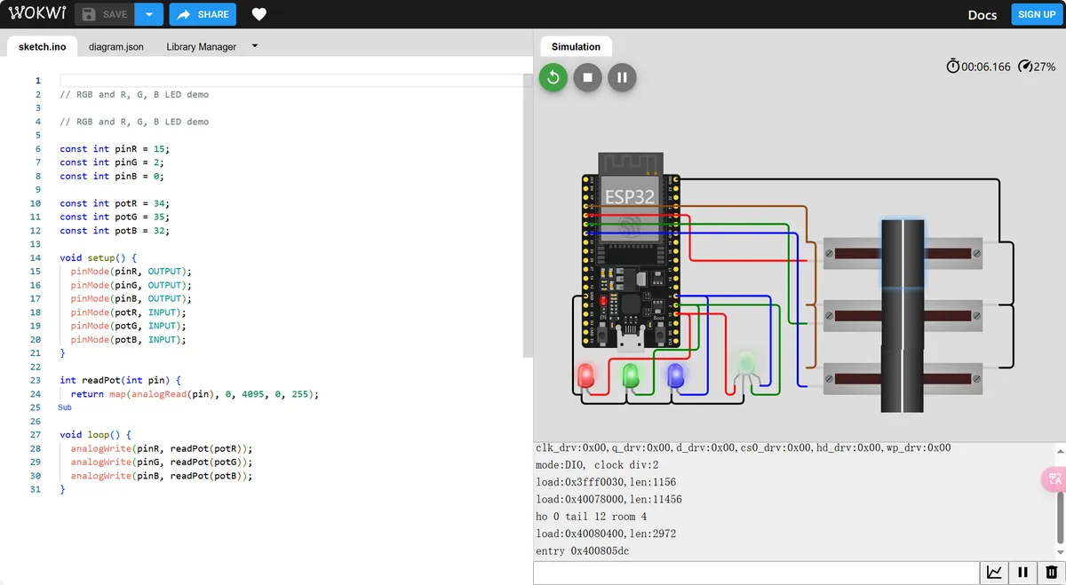
In this experiment, we will control the brightness of the red, green and blue channels of the RGB tri-color LED through three potentiometers respectively, so as to realize the effect of a "manual color palette".
- Rotate potentiometer 1 → adjust the red brightness
- Rotate potentiometer 2 → Adjust the green brightness
- Rotate potentiometer 3 → Adjust blue brightness
When the three primary colors are superimposed, any color (such as yellow, purple, pink, etc.) can be synthesized, allowing you to experience the fun of manual color mixing.
1.1 Experimental Principle
When the potentiometer is rotated, the output voltage will change, and the specific process is as follows:
- The development board reads the voltage via
analogRead ()and obtains a value ranging from 0 to 4095 (ESP32 ADC resolution). - Use the
map ()function to map it to the range of 0~255, which corresponds to the PWM duty cycle range of the LED. - Output PWM waveforms via
analogWrite ()to control the brightness of the LED.
Core Process: Potentiometer → Voltage Change → ADC Sampling (analogRead) → Value Mapping (map) → PWM Output (analogWrite) → RGB LED Brightness Variation
1.2 Hardware Connection
1.2.1 RGB LED
- R Pin → GPIO15
- G pin → GPIO2
- Pin B → GPIO0
- The common cathode is connected to GND
1.2.2 Potentiometer
- PotR (controls red) → GPIO34
- PotG (control green) → GPIO35
- PotB (controls blue) → GPIO32
- The remaining two pins are connected to 3.3V and GND
1.3 Software Implementation Steps
- Define Pins
const int pinR = 15;
const int pinG = 2;
const int pinB = 0;

const int potR = 34;
const int potG = 35;
const int potB = 32;- Perform initialization
void setup() {
  pinMode(pinR, OUTPUT);
  pinMode(pinG, OUTPUT);
  pinMode(pinB, OUTPUT);

  pinMode(potR, INPUT);
  pinMode(potG, INPUT);
  pinMode(potB, INPUT);
}- Write the core function
Convert the potentiometer value to LED brightness
int readPot(int pin) {
  return map(analogRead(pin), 0, 4095, 0, 255);
}- Real-time control of RGB color lights
void loop() {
  analogWrite(pinR, readPot(potR));  // Red brightness
  analogWrite(pinG, readPot(potG));  // Green brightness
  analogWrite(pinB, readPot(potB));  // Blue brightness
}
1.4 Overall Implementation Demonstration
Potentiometer Controlled Colored Lights (ADC+PWM) - Wokwi ESP32, STM32, Arduino Simulator
// RGB and R, G, B LED demo
// RGB and R, G, B LED demo

const int pinR = 15;
const int pinG = 2;
const int pinB = 0;

const int potR = 34;
const int potG = 35;
const int potB = 32;

void setup() {
  pinMode(pinR, OUTPUT);
  pinMode(pinG, OUTPUT);
  pinMode(pinB, OUTPUT);
  pinMode(potR, INPUT);
  pinMode(potG, INPUT);
  pinMode(potB, INPUT);
}

int readPot(int pin) {
  return map(analogRead(pin), 0, 1023, 0, 255);
}

void loop() {
  analogWrite(pinR, readPot(potR));
  analogWrite(pinG, readPot(potG));
  analogWrite(pinB, readPot(potB));
}
2. Potentiometer-Controlled Servo Experiment
In this experiment, the voltage signal (0~3.3V) is adjusted via a potentiometer, then the analog input value of the potentiometer is read through the ADC module of the ESP32, and mapped to the rotation angle range (0°~180°) of the servo. In this way, the effect of "turning the potentiometer → the servo rotates synchronously" can be achieved.
2.1 Experimental Principle
Similarly, when the potentiometer is rotated, the output voltage will change, and the specific process is as follows:
- The development board uses
analogRead ()to collect the voltage value of the potentiometer, obtaining a value ranging from 0 to 4095 (ESP32 ADC resolution). - Use the
map ()function to map it to the range of 0~180, which corresponds to the angle range of the servo. - Call
Servo.write ()function to send the mapped angle value to the servo. - After receiving the PWM signal, the steering gear rotates to the corresponding angle to realize the synchronous change with the position of the potentiometer.
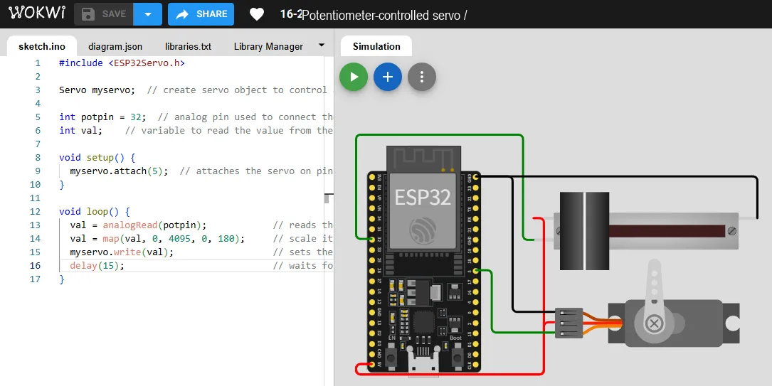
Core Process: Potentiometer → Voltage Change → ADC Sampling (analogRead) → Value Mapping (map) → Servo Angle (Servo.write) → Servo Rotation
2.2 Hardware Connection
2.2.1 Potentiometer
- VCC → 3.3V
- GND → GND
- Middle pin → ADC pin of ESP32 (e. g. GPIO34)
2.2.2 Steering Gear
- Red wire (VCC)→ 5V
- Black wire (GND)→ GND
- Yellow wire (signal line)→ PWM pin of ESP32 (e. g. GPIO18)
Note: The servo requires a 5V power supply, and the 5V pin of the ESP32 can directly supply power to it.
2.3 Software Implementation Steps
- Import library files
#include <ESP32Servo.h>- Define Pins and Objects
int potPin = 34;     // Potentiometer ADC pin
int potValue = 0;    // Stores the potentiometer reading
int angle = 0;       // Servo angle
Servo myServo; // Create servo object- Initialize
void setup() {
  myServo.attach(18);   // Servo signal wire is connected to GPIO18
  Serial.begin(115200);
}- Loop Control
void loop() {
  potValue = analogRead(potPin);          // Read the potentiometer
  angle = map(potValue, 0, 4095, 0, 180); // Map to servo angle
  myServo.write(angle);                   // Control servo rotation
  Serial.print("Potentiometer: ");
  Serial.print(potValue);
  Serial.print("  Servo angle: ");
  Serial.println(angle);
delay(20);  // Short delay to avoid running too fast
}
2.4 Overall Implementation Demonstration
16-2 Potentiometer Controlled Servo - Wokwi ESP32, STM32, Arduino Simulator
#include <ESP32Servo.h>

Servo myservo;  // create servo object to control a servo

int potpin = 32;  // analog pin used to connect the potentiometer
int val;    // variable to read the value from the analog pin

void setup() {
  myservo.attach(5);  // attaches the servo on pin 9 to the servo object
}

void loop() {
  val = analogRead(potpin);            // reads the value of the potentiometer (value between 0 and 1023)
  val = map(val, 0, 4095, 0, 180);     // scale it to use it with the servo (value between 0 and 180)
  myservo.write(val);                  // sets the servo position according to the scaled value
  delay(15);                           // waits for the servo to get there
}
3. Summary of This Chapter
In this chapter, through two experiments — controlling the brightness of an RGB LED with a potentiometer and controlling the angle of a servo with a potentiometer, we systematically demonstrate the application of potentiometers in analog input acquisition and peripheral control.
In the RGB LED experiment, the voltage change of the potentiometer is sampled by ADC (analogRead), then mapped to the PWM duty cycle range via the map () function, and output through analogWrite () to achieve continuous adjustment of LED brightness.
In the servo experiment, the voltage of the potentiometer is also sampled via ADC sampling, and mapped to the 0~180° angle range, then the Servo.write () function outputs a PWM control signal, making the servo position change as the potentiometer rotates.
The two experiments jointly reflect the following key points:
- As an analog input device, a potentiometer can convert the rotation angle into a voltage signal, which can then be acquired by the development board.
- ADC + value mapping + PWM output form the typical "input-processing-output" control flow.
- Different peripherals (LEDs, steering gears) differ in their manifestation, but essentially, they are all controlled via PWM signals.
Through these two cases, we have not only mastered the basic usage of potentiometers, but also understood the general methods of analog quantity acquisition and peripheral control, which lays a foundation for subsequent more complex interactive projects.