
Contents
In embedded systems, motion control and graphic display are two common yet challenging Application Areas. When the two are combined, many interesting and creative projects come into being. In this experiment, we will use a joystick to control the display content of an LED dot matrix, and explore how to convert physical motion into digital control, so as to present intuitive effects on the display screen.
As an analog input device, a joystick can sense changes in multiple directions and generate corresponding analog signals through its horizontal and vertical movements. In this experiment, we will use a joystick to control an 8x8 LED dot matrix; by reading the analog signal with the ESP32, we convert the joystick's displacement into the on/off states of the LEDs in the matrix, and finally display dynamic graphics related to the joystick's position.
Through this experiment, you will not only master how to read the X-axis and Y-axis signals of the joystick, but also learn how to convert these analog signals into intuitive visual outputs through simple mathematical calculations and mapping. This not only enhances your understanding of analog input device control, but also gives you a deeper insight into how to implement graphical display and dynamic interaction in embedded systems.
1. Introduction
Use the joystick of the gamepad to control the movement of the light spots on the LED dot matrix screen, and press the joystick button to clear the screen, which is similar to the effect of a handheld console joystick controlling the movement of a game character.
In this lesson, we will implement the joystick control of the LED dot matrix. In previous lessons, we have already learned about the joystick experiment, and this LED dot matrix is something we encounter for the first time.
2. LED Dot Matrix
An LED dot matrix is a display device composed of multiple LEDs arranged in rows and columns. Each LED is referred to as a "dot", and by controlling the on and off states of these dots, information such as numbers, letters, and graphics can be displayed.
For example, an 8×8 LED matrix consists of 8 rows and 8 columns, with a total of 64 LED lamps.
- Consists of multiple LED lights arranged in rows and columns, and each LED light is referred to as a "pixel"
- Example: An 8×8 LED dot matrix with a total of 64 LED lamps
2.1 Internal Chip – MAX7219
However, if you want to control these 64 LEDs and connect a separate wire to each of them, you will need as many as 64 control lines alone, which is far too complicated and will occupy a large number of microcontroller pins. To address this issue, common dot matrix modules integrate dedicated driver chips, and the MAX7219 is one of the most classic models among them.
The MAX7219 is a chip specifically designed for controlling LED dot matrix displays. Its biggest advantage is that it can easily control an 8*8 dot matrix using only 3 signal lines.
The controller only needs to send commands and data to the MAX7219 through a simple 3-wire serial interface (SPI), and the MAX7219 will automatically complete the tedious scanning, refreshing and driving work, thus greatly simplifying hardware design and software programming.
2.2 Dot Matrix Pins and Functions
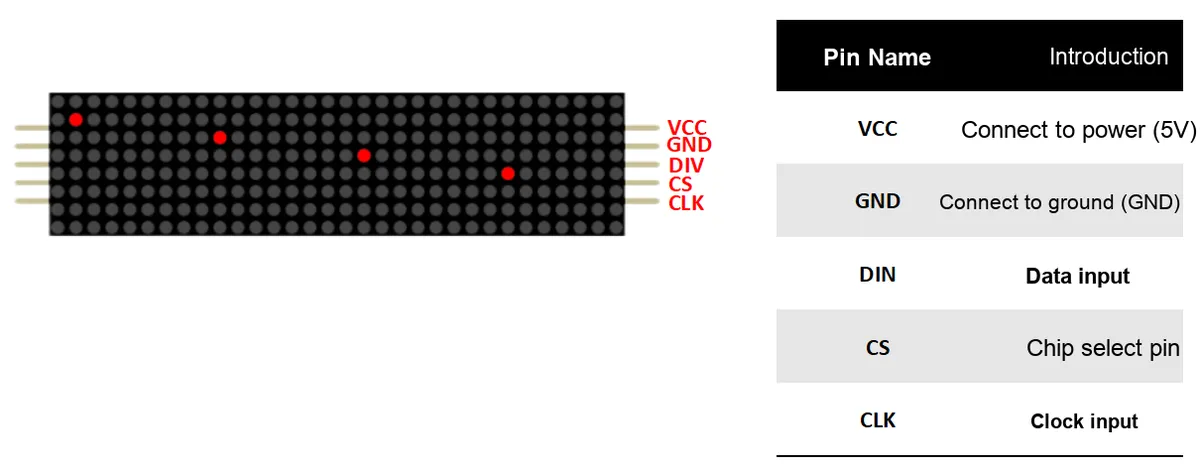
2.2.1 Pin Description
- CS (Chip Select, chip select signal)
- When CS is at low level (0), the MAX7219 starts receiving data.
- When CS is at a high level (1), the MAX7219 latches the data and executes the instruction that has just been sent.
- Therefore, after the data transmission is completed, the CS pin must be pulled high; otherwise, the MAX7219 will not update the display.
- CLK (Clock, clock signal)
- Function: Synchronize data transmission and control the timing of data
- DIN (Data In, data input)
- Function: Transmit control commands and the dot matrix data to be displayed
- Synchronized by the CLK clock, the controller sends data to the DIN pin bit by bit.
- The data content includes the following:
- Control commands (such as adjusting brightness, setting scan mode)
- Dot matrix display data (which LEDs to turn on or off)
2.2.2 Summary: Data Transmission Process
- Pull down CS (start transmission)
- Transmit data (DIN) bit by bit in accordance with clock pulses (CLK)
- After data transmission is complete, pull CS high (latch and execute)
3. Software Implementation Method for Dot Matrix Lighting
Then how to control the dot matrix? You can do so by calling the MAX72xx.h library function
3.1 Understand MAX72xx library function
3.1.1 MAX72xx Library Introduction
MAX72xx library is a secondary encapsulation for chip operation, which converts tedious timing operations into simple function calls.
With this library, we can:
- Turn on/off a specific LED dot;
- Display numbers and letters;
- Display strings and scrolling subtitles;
- Easily expand the cascade display of multiple dot matrix modules.
Beginners don't need to care about the underlying hardware communication at all; they only need to know how to use a few functions to make the dot matrix display content.
3.1.2 Core Functions
When using this library, common functions fall into the following categories (introduced in the order of usage):
- Initialization function
begin()
Function: Initialize SPI communication and configure the parameters of the MAX7219 chip.
- Set function
control(uint8_t mode, uint8_t value)
Function: Set the operating mode of the chip.
Parameters:
mode: Control modes (e. g., brightness, power-off mode, scan limit, etc.)value: mode parameter value
| Function |
|
| Adjust Brightness | 0 (dimmest) - 15 (brightest) |
| Shutdown/Startup | false (shutdown)/true (startup) |
| Set the number of scan lines | 0 (Line 1) - 7 (Line 8) |
- clear screen function
clear()
- Function: Clear all LED displays (turn all off).
- Note: Must be used in conjunction with
update ()to take effect immediately.
- Point operation function
setPoint(uint8_t row, uint8_t col, bool state)
- Function: Control the on/off state of a single LED.
- Parameters:
rowRow number (0-7)col: Column number (ranges from 0 to 7 for a single module; the range will be extended when multiple modules are cascaded)state:trueon,falseoff
- update function
update()
- Function: Flush the cached data to the hardware display (must be called after all modification operations).
- Note: After modifying
setPoint/setRowand other functions, you need to call this function to take effect.
3.1.3 Software Design Procedures
- Import library files
Include the MAX72xx.h driver library at the beginning of the code.
#include <MD_MAX72XX.h>- Define Pins
Define the pins to be connected and other relevant parameters:
// === 1. Define pins and parameters ===

#define MAX_DEVICES 4   // Number of dot-matrix modules (4 MAX7219 = 4 8x8 dot matrices)

#define CLK_PIN 18   // // Clock (CLK)   (modify according to your actual wiring)
#define DIN_PIN 23  // // Data input (DIN)  (modify according to your actual wiring)
#define CS_PIN 21 // Chip select (CS) (modify according to your actual wiring)DIN_PIN: Data input pin, connected to the DIN pin of the MAX7219.
CLK_PIN: Clock pin, connected to the CLK pin of the MAX7219.
CS_PIN: Chip select pin, connected to the CS pin of MAX7219.
MAX_DEVICES: Indicates the number of MAX7219 LED dot matrix displays you are connecting. It is usually set to 1, and a maximum of 8 devices are supported.
Note: Each MAX7219 chip supports a maximum of one 8x8 dot matrix module. If you have connected multiple modules, set the number of modules in this parameter.
- Create an object
Then create an MD_MAX72XX object
MD_MAX72XX mx = MD_MAX72XX(MD_MAX72XX::PAROLA_HW, CS_PIN, MAX_DEVICES);Parameters | Type | Description |
MD_MAX72XX::PAROLA_HW | Constants (Enumeration Values) | Specify the hardware type (arrangement mode) of the LED dot matrix module. Common examples include: - - - |
CS_PIN | int (GPIO pin number) | The chip select pin is responsible for telling the MAX7219 chip when to start/end a data transmission. When CS is pulled low, the chip starts to receive data input from DIN (data line) and driven by CLK (clock line). When CS is pulled high, the chip latches (stores) the data just received and updates it to the dot matrix display. |
MAX_DEVICES | int | The number of connected MAX7219 modules (one module corresponds to one 8×8 dot matrix). For example, if you define |
- Initialize the MAX7219
In the setup () function, initialize the LED dot matrix.
void setup() {
  Serial.begin(115200);  // Initialize serial, baud rate set to 115200
  mx.begin();
  mx.control(MD_MAX72XX::INTENSITY, MAX_INTENSITY / 2);
  mx.clear();
}- Control the content displayed on the dot matrix
First set the specified position and then update the display, and you will be able to see the effect!
void loop() {
  // Update the LED matrix display
  mx.setPoint(4, 4, true);
  mx.update();

  delay(100);  // Set a delay so the debug information can be observed more clearly
}
3.1.4 Overall Implementation
A complete sample program is provided below to demonstrate how to initialize the MAX7219 dot matrix and turn a specific pixel on or off.
15-1 Dot Matrix Control - Wokwi ESP32, STM32, Arduino Simulator
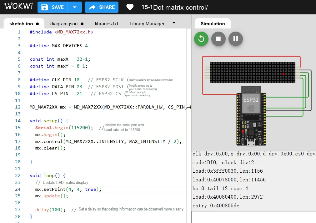
#include <MD_MAX72xx.h>

// === 1. Define pins and parameters ===
#define MAX_DEVICES 4

#define CLK_PIN 18   // ESP32 SCLK (modify according to your actual wiring)
#define DIN_PIN 23  // ESP32 MOSI (modify according to your actual wiring)
#define CS_PIN   21   // ESP32 CS (modify according to your actual wiring)

MD_MAX72XX mx = MD_MAX72XX(MD_MAX72XX::PAROLA_HW, CS_PIN, MAX_DEVICES);

void setup() {
  Serial.begin(115200);  // Initialize serial, baud rate set to 115200
  mx.begin();
  mx.control(MD_MAX72XX::INTENSITY, MAX_INTENSITY / 2);
  mx.clear();
}

void loop() {
  // Update the LED matrix display
  mx.setPoint(4, 4, true);
  mx.update();

  delay(100);  // Set a delay so the debug information can be observed more clearly
}
📌 Note:
mx.setPoint (row, col, true/false)→ Controls whether a specific point is lit or not.mx.update ()→ Refresh the display (this method must be called for the changes to take effect).
4. Example Implementation Steps
4.1 Hardware Connection
We need to connect the joystick module on the basis of the original control dot matrix:
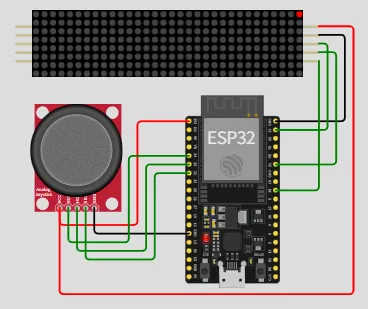
4.1.1 Joystick Module Connection
Joystick pin | Functions | ESP32 Pins |
|---|---|---|
VCC | positive electrode of power supply | 3.3V |
GND | Earth | GND |
HORZ | Horizontal Analog Quantity | GPIO 35 (HORZ_PIN) |
VERT | Vertical Analog Quantity | GPIO 34 (VERT_PIN) |
SEL | button | GPIO 32 (SEL_PIN) |
4.1.2 Connection of MAX7219 Dot Matrix Module
MAX7219 Pins | Functions | ESP32 Pins |
|---|---|---|
VCC | positive electrode of power supply | 5V (5V is recommended for higher brightness; 3.3V is also acceptable) |
GND | Earth | GND |
DIN | Data Input | GPIO 23 (DATA_PIN) |
CLK | clock signal | GPIO 18 (CLK_PIN) |
CS | Chip Select | GPIO 21 (CS_PIN) |
4.1.3 Data Flow Logic
- Joystick is pushed → VRx and VRy voltages change → ESP32 reads them via
analogRead (). - The ESP32 converts the voltage into coordinates (x, y).
- ESP32 calls the MAX72xx library function
mx.setPoint (y, x, true)→ to turn on the pixel at the specified coordinates. - The MAX7219 receives an instruction → and turns on a small LED at the corresponding position on the dot matrix.
4.2 Software Design and Deployment
- Basic preparation: Import library functions, define the dot matrix pins, joystick input pins and the maximum coordinates of the dot matrix, and create a dot matrix object.
#include <MD_MAX72xx.h>

#define MAX_DEVICES 4

const int maxX = 32-1;
const int maxY = 8-1;

#define CLK_PIN 18   // ESP32 SCLK (modify according to your actual wiring)
#define DATA_PIN 23  // ESP32 MOSI (modify according to your actual wiring)
#define CS_PIN   21   // ESP32 CS (modify according to your actual wiring)

#define VERT_PIN 34  // Analog input, used to read the vertical axis of the joystick (modify according to your actual wiring)
#define HORZ_PIN 35  // Analog input, used to read the horizontal axis of the joystick (modify according to your actual wiring)
#define SEL_PIN  32  // Digital input, used to read the joystick button (modify according to your actual wiring)

MD_MAX72XX mx = MD_MAX72XX(MD_MAX72XX::PAROLA_HW, CS_PIN, MAX_DEVICES);- Configure the joystick input pins
  pinMode(VERT_PIN, INPUT);
  pinMode(HORZ_PIN, INPUT);
pinMode(SEL_PIN, INPUT_PULLUP);- Read the pin output value
  // Read the horizontal and vertical axes of the joystick
  int horz = analogRead(HORZ_PIN);
  int vert = analogRead(VERT_PIN);
  int sel = digitalRead(SEL_PIN);

  // Output debug information
  Serial.print("Horizontal: ");
  Serial.print(horz);
  Serial.print(" | Vertical: ");
  Serial.print(vert);
  Serial.print(" | Button: ");
Serial.println(sel == LOW ? "Pressed" : "Released");- Initialize a position on the dot matrix and light it up.
int x = 0;
int y = 0;

// Update the LED matrix display
mx.setPoint(y, x, true);
mx.update();
delay(100); // Set the delay- Determine whether the joystick is moved, and if so, update the position coordinates of the dot matrix
Before that, we need to know that the value range of the joystick is:
           Y轴
      Push up ↑ 4095 (middle value)
          |
4095 ←Push left--[Origin]2048--Push right→ 0 X-axis
          |
      Push down ↓ 0
Determine the moving direction of the light spot according to the read joystick value.
vert > 2048: Move Upvert < 2048: move downhorz > 2048: Move lefthorz < 2048: Move right
// Update position based on joystick input
if (vert < 2048) {
y = min(y + 1, maxY);
}
if (vert > 2048) {
y = max(y - 1, 0);
}
if (horz > 2048) {
x = min(x + 1, maxX);
}
if (horz < 2048) {
x = max(x - 1, 0);
}
// If the button is pressed, clear the display
if (sel == LOW) {
mx.clear();
}
Now our experiment of controlling the LED matrix with the joystick is completed!
4.3 Overall Implementation
4.1 Joystick Controlled Dot Matrix - Wokwi ESP32, STM32, Arduino Simulator
#include <MD_MAX72xx.h>

#define MAX_DEVICES 4

const int maxX = 32-1;
const int maxY = 8-1;

#define CLK_PIN 18   // ESP32 SCLK (modify according to your actual wiring)
#define DATA_PIN 23  // ESP32 MOSI (modify according to your actual wiring)
#define CS_PIN   21   // ESP32 CS (modify according to your actual wiring)

#define VERT_PIN 34  // Analog input, used to read the vertical axis of the joystick (modify according to your actual wiring)
#define HORZ_PIN 35  // Analog input, used to read the horizontal axis of the joystick (modify according to your actual wiring)
#define SEL_PIN  32  // Digital input, used to read the joystick button (modify according to your actual wiring)

MD_MAX72XX mx = MD_MAX72XX(MD_MAX72XX::PAROLA_HW, CS_PIN, MAX_DEVICES);

int x = 0;
int y = 0;

void setup() {
  Serial.begin(115200);  // Initialize serial, baud rate set to 115200
  mx.begin();
  mx.control(MD_MAX72XX::INTENSITY, MAX_INTENSITY / 2);
  mx.clear();

  pinMode(VERT_PIN, INPUT);
  pinMode(HORZ_PIN, INPUT);
  pinMode(SEL_PIN, INPUT_PULLUP);
}

void loop() {
  // Read the horizontal and vertical axes of the joystick
  int horz = analogRead(HORZ_PIN);
  int vert = analogRead(VERT_PIN);
  int sel = digitalRead(SEL_PIN);

  // Output debug information
  Serial.print("Horizontal: ");
  Serial.print(horz);
  Serial.print(" | Vertical: ");
  Serial.print(vert);
  Serial.print(" | Button: ");
  Serial.println(sel == LOW ? "Pressed" : "Released");

  // Update position based on joystick input
  if (vert < 2048) {
    y = min(y + 1, maxY);
  }
  if (vert > 2048) {
    y = max(y - 1, 0);
  }
  if (horz > 2048) {
    x = min(x + 1, maxX);
  }
  if (horz < 2048) {
    x = max(x - 1, 0);
  }

  // If the button is pressed, clear the display
  if (sel == LOW) {
    mx.clear();
  }

  // Update the LED matrix display
  mx.setPoint(y, x, true);
  mx.update();

  delay(100);  // Set a delay so the debug information can be observed more clearly
}
5. Summary of This Chapter
In this chapter, we combine the joystick module and the LED dot matrix to implement an interesting interactive experiment: you can control the movement of the light spot on the dot matrix screen by pushing the joystick, and pressing the joystick button can also clear the screen.
This chapter describes how to use the MAX7219 to drive an LED dot matrix, and implement light spot movement in combination with the joystick module. The main contents are as follows:
- Understand the MAX7219 chip and its 3-wire control mode;
- Learn to use the common functions of the MAX72xx library (
begin (),setPoint (),clear (),update ()); - Control the movement of light spots on the dot matrix by reading the joystick input, and press the button to clear the screen.
Mastered the basic method of combining input devices (joysticks) and output devices (dot matrix displays).