In the world of embedded systems, we often face the challenge of converting analog signals into digital control. This process is not merely a matter of technical mastery, but also a way to enable interaction with the physical world. In this experiment, we will use a potentiometer to control a 10-segment LED light strip to achieve a highly intuitive Progress Bar effect.
As an analog input device, a potentiometer can provide a continuously varying voltage signal. We convert this signal into a digital signal, and control the on-off states of multiple LEDs via the ESP32 to display different brightness levels. This project not only helps you understand how analog signals affect digital outputs, but also lets you experience just how simple and fun the process of controlling a light strip can be.
Through this experiment, you will gain an in-depth understanding of how to read the voltage value of a potentiometer, how to perform value mapping, and convert such data into practical LED control. It not only demonstrates simple analog signal reading, but also provides you with a flexible approach to help you better master the conversion and control between digital and analog signals, serving as a solid cornerstone for your learning of embedded systems.
1. 10-segment LED strip light
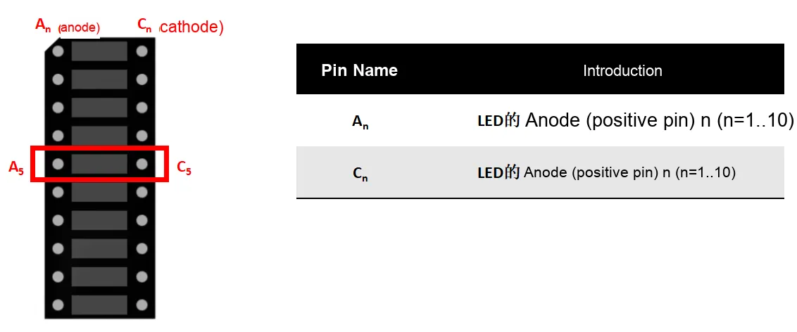
A 10-segment LED bar graph consists of 10 individual LEDs arranged in a column. Each LED can be connected to a GPIO pin of a microcontroller and lit up independently to indicate different statuses or value ranges. It is commonly used in circuits as a graphical representation for displaying value ranges, progress or statuses.
Terminal A serves as the anode terminal, and terminal C serves as the cathode terminal. For example, A5 is the anode of the fifth LED, and C5 is the cathode of the fifth LED. During connection, connect the anode to the GPIO pin and the cathode to GND, then you can realize the control over the LED strip.
2. Implementation Method
Controlling a 10-segment LED bar graph is relatively straightforward — it’s just like using 10 GPIO pins on the ESP32 to control 10 individual LEDs, so let’s get straight to hands-on operation.
2.1 Hardware Connection
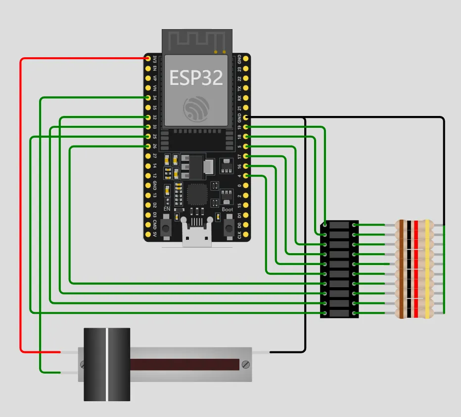
First, let's connect the ESP32 to the potentiometer and the 10-segment LED bar graph.
2.2 Software Design Steps
First perform the macro definition
const int analogPin = 34;   // Analog input pin on the ESP32
const int ledCount = 10;    // Number of LEDs

int ledPins[] = {
  19, 18, 5, 17, 16, 4, 26, 32, 33, 25
};   // Pin array: digital output pins on the ESP32 that control the LEDs
Configure the pin modes one by one via the for loop
  // Set the pins of all LEDs to output mode
  for (int thisLed = 0; thisLed < ledCount; thisLed++) {
    pinMode(ledPins[thisLed], OUTPUT);
  }
  // Set the analog input pin to input mode
  pinMode(analogPin, INPUT);
Read the potentiometer value
int sensorReading = analogRead(analogPin);
Map the values to the number of LEDs
  // Map the input value to the range 0 to the number of LEDs
  int ledLevel = map(sensorReading, 0, 4095, 0, ledCount);  // The ESP32 ADC range is 0-4095
Function prototype: long map(long value, long fromLow, long fromHigh, long toLow, long toHigh)
Input Parameters:
value - The original value to be converted (e. g., ADC reading of a potentiometer)
fromLow - the minimum value of the original range (e. g., the minimum ADC value)
fromHigh - the maximum value of the original range (e. g. the maximum ADC value)
toLow - the minimum value of the target range (e. g. the minimum number of LEDs is 0)
toHigh - The maximum value of the target range (e. g., the maximum number of LEDs is 10)
Return value: The converted value in the target range
Working principle: The map () function calculates via linear interpolation, with the formula as follows:
Example:
Assumption:
Potentiometer ADC range: 0~4095;
LED quantity range: 0~10;
When the read ADC value equals 2048:
At this point, 5 LEDs will light up.
Turn on the corresponding number of LEDs according to the mapping result
// Loop to control the LEDs
for (int thisLed = 0; thisLed < ledCount; thisLed++) {
    // Turn the LEDs on or off according to the mapping result
    if (thisLed < ledLevel) {
      digitalWrite(ledPins[thisLed], HIGH);
    }
    else {
      digitalWrite(ledPins[thisLed], LOW);
    }
}
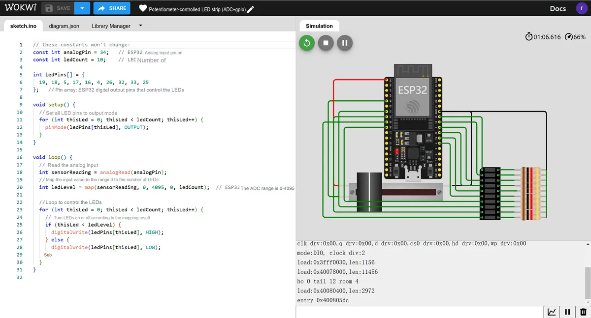
// these constants won't change:
const int analogPin = 34;   // Analog input pin on the ESP32
const int ledCount = 10;    // Number of LEDs

int ledPins[] = {
  19, 18, 5, 17, 16, 4, 26, 32, 33, 25
};   // Pin array: digital output pins on the ESP32 that control the LEDs

void setup() {
  // Set the pins of all LEDs to output mode
  for (int thisLed = 0; thisLed < ledCount; thisLed++) {
    pinMode(ledPins[thisLed], OUTPUT);
  }
}

void loop() {
  // Read the analog input
  int sensorReading = analogRead(analogPin);
  // Map the input value to the range 0 to the number of LEDs
  int ledLevel = map(sensorReading, 0, 4095, 0, ledCount);  // The ESP32 ADC range is 0-4095

  // Loop to control the LEDs
  for (int thisLed = 0; thisLed < ledCount; thisLed++) {
    // Turn the LEDs on or off according to the mapping result
    if (thisLed < ledLevel) {
      digitalWrite(ledPins[thisLed], HIGH);
    } else {
      digitalWrite(ledPins[thisLed], LOW);
    }
  }
}
4. Summary of This Chapter
In this chapter, through the project of controlling the LED strip with a potentiometer, we practiced the comprehensive application of analog signal reading and digital output. We learned how to use the ADC function of ESP32 to read the voltage value of the potentiometer, convert the analog quantity ranging from 0 to 4095 into the digital quantity ranging from 0 to 10 via the map () function, and finally visually display the conversion result through the LED strip. This project fully demonstrates the entire process from analog signal acquisition, value conversion to output control, which is a typical example for learning the analog-to-digital conversion technology in embedded systems.