
Contents
In the previous chapters, we discussed how to precisely control signal intensity through Pulse Width Modulation (PWM), which lays a foundation for driving various electronic devices. Now, as our understanding of signal control deepens, we are faced with a brand-new challenge: how to convert these signals into actual mechanical motion?
A servo motor is an electric motor that controls its position via electrical signals, and it plays a vital role in modern electronics and robotics. It is widely used for precise position control in applications ranging from remote-controlled toys and robotic arms to automated equipment. And the secret behind it lies in the PWM modulation we learned earlier.
This chapter will walk you through the working principle of servos and guide you on how to use the ESP32 to precisely control the angle of a servo via PWM signals. Through this experiment, you will not only observe how code and circuits work in tandem, but also get hands-on experience making mechanical components respond to your commands to complete practical tasks. Whether you are building robots or designing automation systems, mastering servo control will be a critical step for you to advance to more sophisticated electronics projects.
Let's take this small step to convert digital signals into physical motion and unveil the magic behind smart device control!
1. External wiring of the steering gear
A servo motor, whose full name is servo motor, is a commonly used position control actuator.
All servo motors have three external wires, which are distinguished by three colors: brown, red and orange respectively.
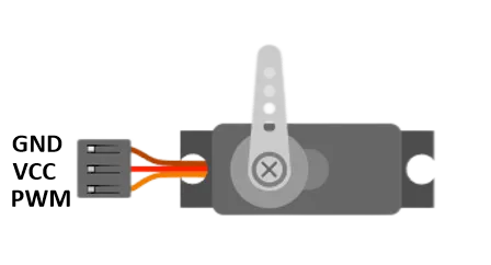
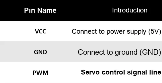
Three external wires:
- Brown — GND (Ground)
- Red — VCC (power supply, typically 5V)
- Orange — Signal wire (connect to PWM control pin)
Brown is the ground wire - GND, red is the positive power wire - 5V, and orange is the signal wire - analog output pin.
2. Internal Core Components
Inside the housing of a servo motor, there is actually a complete miniature control system hidden. Its core consists of four components: a motor, a reduction gear set, a potentiometer, and a control circuit.
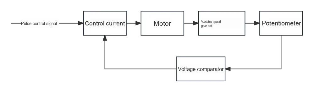
First, a DC motor is used as the power source inside the servo. The motor itself runs at a very high speed but produces relatively low torque, making it impractical to directly use it to drive the servo arm. Therefore, a set of reduction gears is connected after the motor. On one hand, these gears reduce the motor's rotational speed; on the other hand, they significantly increase the output torque, enabling the servo to stably drive loads despite its compact size.
On the output shaft, a potentiometer is also installed. The potentiometer rotates synchronously with the steering arm, functioning as an "angle sensor". When the servo rotates, the potentiometer generates a corresponding voltage signal, which is fed back to the internal control circuit of the servo in real time.
The control circuit serves as the "brain" of the entire servo. First, it receives the external PWM pulse signal and interprets the target angle based on the pulse width of the signal; at the same time, it continuously reads the current position voltage fed back by the potentiometer. Through a voltage comparator, the control circuit compares the target position with the current position. If there is a discrepancy between the two, it immediately adjusts the rotation direction and current magnitude of the motor to drive the motor to rotate until the servo turns to the target position. Once the current position matches the target position, the control circuit stops driving the motor, keeping the servo held at the specified angle.
Therefore, a servo is not a simple electric motor, but a miniature device equipped with a "closed-loop control system". The PWM pulse signal acts like a "command", the motor and gears are responsible for "execution", the potentiometer provides "feedback", and the control circuit constantly "compares and corrects" to ensure that the servo stops precisely at the target angle.
Internal Core Components:
DC motor
- It serves as the power source for the steering gear, but it should be noted that the motor itself features high rotational speed and low torque, so it cannot directly drive the steering arm.
Reduction Gear Set
- It converts the high-speed rotation of the motor into low-speed and high-torque output, ensuring that the steering gear can stably drive the load even with a small volume.
Potentiometer (Position Sensor)
- Connected to the output shaft, it detects the current rotation angle of the steering gear in real time and converts the angle into an analog voltage signal for feedback.
control circuit
- Receive external PWM pulse signals (control commands).
- By means of voltage comparator, the target position corresponding to the PWM command is compared with the current position fed back by the potentiometer.
- Adjust the direction and magnitude of the motor current according to the error, and drive the motor to rotate until the steering gear turns to the target angle.
A closed-loop control system is formed internally, which keeps adjusting to reach and maintain the target angle.
- Motor + gear set → provides power and output torque
- Potentiometer → Provides angular position feedback
- Control circuit → responsible for "comparison and correction" to keep the servo at the commanded position
3. Additional Notes: Open-loop and Closed-loop
Before truly understanding servos, we need to distinguish between two common control modes: open-loop control and closed-loop control.
3.1 Open-loop Control
Open-loop control means that the controller only issues instructions without detecting the results.
- Advantages: simple implementation and low cost.
- Disadvantages: It cannot guarantee accurate results, and deviations will occur once the execution process is disturbed.
- Similar to "blind execution": an order is given, yet no regard is paid to whether the intended outcome is actually achieved.
For example, we want to control the car to travel 2 meters along a straight line.
In open-loop control, the motor speed and duration are set, but there is no feedback mechanism. If the trolley deviates from its path or encounters an obstacle, the system cannot make adjustments, and it may fail to travel the exact 2-meter distance.
┌─────────┐    ┌─────────┐    ┌─────────┐
│  Input signal  │───>│ Controller/Algorithm │───>│ Actuator/Device │───> Output
└─────────┘    └─────────┘    └─────────┘
3.2 Closed-loop Control
Closed-loop control is different: it not only issues instructions, but also detects the execution results in real time and makes corrections accordingly.
- Core features: with feedback.
- The controller compares the "target value" with the "actual value", and if there is an error, it adjusts the output until the error is minimized.
- It is similar to "automatic correction": just like when driving, you constantly adjust your route based on the steering wheel and lane conditions.
Closed-loop control: The car monitors its position in real time, and the control system adjusts the rotational speed based on feedback to ensure it travels exactly 2 meters.
┌─────────┐    ┌─────────┐    ┌─────────┐    ┌─────────┐
│  Target value  │─┬─>│ Controller/Algorithm │───>│ Actuator/Device │───> Output
└─────────┘ │  └─────────┘    └─────────┘       │
                ▼  ┌──────────────┐       │
                │  │ Sensor/Measurement Unit │<───────┘
                └─< Feedback signal processing    │
                   └──────────────┘
A servo motor is a typical example of closed-loop control.
3.3 Why does a steering gear require closed-loop control?
The core value of a servo motor lies in its ability to rotate precisely to a specified angle. Without feedback, the rotation of the motor is completely uncontrollable, and it will most likely stop at the wrong position. With closed-loop control, however, the servo can reach the target angle stably and accurately while resisting external disturbances.
4. Steering Gear Angle Control
A servo motor is a common actuator whose rotation angle is not directly determined by the voltage level, but is controlled by the pulse width of PWM pulses. Unlike LED dimming which uses duty cycle to represent "brightness", servo motor control signals have much stricter timing specifications.
4.1 Control Signal Characteristics
Fixed period: The period of common servo control signals is 20ms (50Hz).
Pulse width determines the angle:
- 1ms high level → the servo rotates to the minimum angle (typically 0°).
- 1.5ms high level → the servo rotates to the intermediate angle (typically 90°).
- 2ms high level → the servo rotates to the maximum angle (typically 180°).
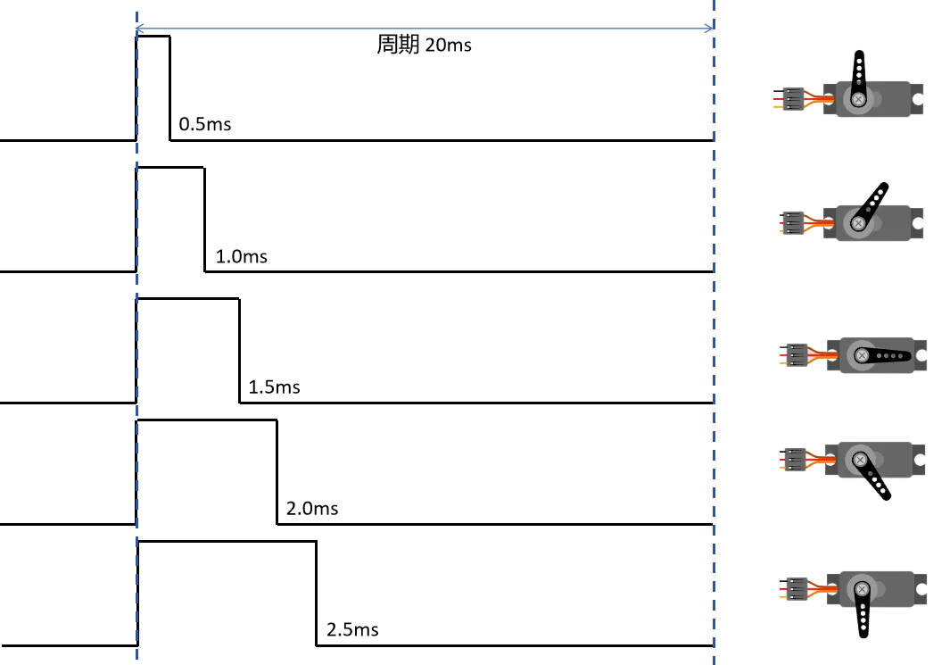
The range may vary slightly among different servo models; for example, 0.5ms ~ 2.5ms corresponds to 0° ~ 180°.
4.2 Summary of Features
- A servo motor is a closed-loop control system featuring accurate positioning.
- The angle of a servo motor is determined by the "pulse width within a fixed period", not by the duty cycle. We cannot simply use the "duty cycle percentage" to explain the angle; instead, we must focus on the absolute pulse width time.
- Within a 20ms cycle, a 1.5ms high level results in a 7.5% duty cycle, which rotates the servo to 90°.
- If the period is changed to 10ms, with a 1.5ms high level → the duty cycle becomes 15% → but the servo will not recognize this as a 90° command and may move erratically.
- Commonly used in robot joints, remote-controlled cars, robotic arms and other scenarios that require precise angle control.
5. Software Design
5.1 Directly Control Servos Using LEDC Series Functions
5.1.1 PWM Parameter Setting
- Fixed period: 20ms (frequency 50Hz)
- Valid pulse width range: 1ms ~ 2ms
- Resolution: Commonly 10~16 bits (to ensure sufficiently fine pulse width control)
5.1.2 Software Design Steps
- Macro Definition Parameters
// Parameters
const int SERVO_PIN = 18;
const int SERVO_CH  = 0;
const int SERVO_FREQ = 50;      // 50 Hz
const int SERVO_RES = 16; // 16-bit- Set PWM frequency and resolution
Call ledcSetup (channel, freq, resolution) to set the PWM frequency and resolution
ledcSetup(SERVO_CH, SERVO_FREQ, SERVO_RES); // Channel 0, frequency 50Hz, 16-bit resolution- Bind pins to channels
Call ledcAttachPin (pin, channel) to bind the pin to the channel
ledcAttachPin(SERVO_PIN, SERVO_CH); // SERVO_PIN = GPIO18 → SERVO_CH = 0- Calculate the duty value corresponding to the pulse width
Servo angle = 1ms (0°) ~ 2ms (180°)
Within the 20ms period, convert the range of 1000µs to 2000µs into duty cycle.
int duty = map(angle, 0, 180, 3277, 6553);
// 3277 ≈ 5% duty (1ms), 6553 ≈ 10% duty (2ms)- output control signal
Use ledcWrite (channel, duty) to output PWM signals to control the angle of the servo
ledcWrite(SERVO_CH, duty);This map () range is based on the duty at 16-bit resolution.
Why is the range 3277 to 6553?
- Since 50Hz → period = 20ms, the maximum value of 16 bits = 65536
- 1ms pulse width:
1000 / 20000 * 65536 ≈ 3277 - 2ms pulse width:
2000 / 20000 * 65536 ≈ 6553
5.1.3 Overall Implementation
The following code demonstrates how to use the LEDC series functions to control a servo to achieve cyclic motion from 0° → 90° → 180°.
// =======================
// Servo control example (LEDC)
// =======================

// Parameter definitions
const int SERVO_PIN = 18;     // GPIO connected to the servo signal line
const int SERVO_CH  = 0;      // Use channel 0
const int SERVO_FREQ = 50;    // Servo requires 50Hz (20ms period)
const int SERVO_RES  = 16;    // 16-bit resolution

// Function declarations
void writeServoAngle(int angle);

void setup() {
  // 1. Set up PWM channel: frequency 50Hz, 16-bit resolution
  ledcSetup(SERVO_CH, SERVO_FREQ, SERVO_RES);

  // 2. Bind GPIO to the specified channel
  ledcAttachPin(SERVO_PIN, SERVO_CH);
}

void loop() {
  // Rotate to 0°, 90°, 180° in turn, pausing 1 second each time
  writeServoAngle(0);
  delay(1000);

  writeServoAngle(90);
  delay(1000);

  writeServoAngle(180);
  delay(1000);
}

// Convert the angle to a PWM duty cycle and output it
void writeServoAngle(int angle) {
  // At 16-bit resolution:
  // 1ms ≈ 3277, 2ms ≈ 6553
  int duty = map(angle, 0, 180, 3277, 6553);

  // Output the PWM signal
  ledcWrite(SERVO_CH, duty);
}
5.2 Controlling Servos via ESP32Servo Library
5.2.1 ESP32Servo Library Introduction
ESP32Servo library is a servo control library specifically designed for the ESP32. It leverages the LEDC hardware module of the ESP32 to generate stable PWM signals, aiming to simplify the PWM signal control of the ESP32.
It is essentially a wrapper for the ESP32 LEDC PWM function, which frees developers from having to calculate the PWM frequency, resolution and duty, and they only need to directly input the servo angle.
Internally, PWM is set by default to 50Hz (period: 20ms), and the PWM pulse width corresponding to the angle is calculated based on the minimum/maximum pulse width (µs) passed in by the attach () function.
5.2.2 Core Function
The ESP32Servo library is essentially a "servo control toolkit" that comes with a set of commonly used built-in functions, making it extremely easy for us to operate servo motors.
We only need to obtain a servo controller first (for example, Servo myServo;), and then we can use the following buttons to operate it:
attach(pin, minUs, maxUs):- Bind the PWM output pin and specify the minimum/maximum pulse width (default values are 500us and 2400us)
myServo.attach(18, 500, 2400);
write (angle): Set the servo angle (0° ~ 180°)myServo.write (90); // Turn to 90 degrees
detach (): Releases the pin and stops signal outputmyServo.detach (); // Disengage the servo
read (): Read the current servo angleint pos = myServo.read (); // Read the servo angle
5.2.3 Software Design Procedures
- Import the library file: First, import the ESP32Servo library into your code.
#include <ESP32Servo.h>- Create a servo object: This object acts as a tool for you to control the servo, through which you can tell the servo which angle to rotate to.
Servo myServo; // Object name: myServo (customizable)- Set the servo pin: Tell the ESP32 which pin the servo is connected to.
myServo.attach(18); // Servo plugged into GPIO18- Control the servo: Write the angle command directly in the
loop ()function, and use simple commands to make the servo rotate to the angle you want.
myServo.write(90);   // Rotate to 90°
delay(1000);         // Pause 1 second
myServo.write(0);    // Rotate to 0°
delay(1000);
myServo.write(180);  // Rotate to 180°
delay(1000);
5.2.3 Overall Implementation
Here is a complete sample code demonstrating how to use the ESP32Servo library to control a servo to swing back and forth between 0°, 90°, and 180°.
13-1 Controlling a Servo with the ESP32Servo Library - Wokwi ESP32, STM32, Arduino Simulator
#include <ESP32Servo.h>   // Include the servo library

Servo myServo;            // Create a servo controller

void setup() {
  myServo.attach(18);     // Connect the servo to GPIO18
}

void loop() {
  myServo.write(0);       // Rotate to 0°
  delay(1000);            // Wait 1 second

  myServo.write(90);      // Rotate to 90°
  delay(1000);

  myServo.write(180);     // Rotate to 180°
  delay(1000);
}
6. Example: Controlling two servo motors
13-2 Controlling Two Servos with Library Functions - Wokwi ESP32, STM32, Arduino Simulator
#include <ESP32Servo.h>  // Import the servo library

// Define the signal pins of the two servos (customizable)
const int servoPin1 = 18;  // First servo connected to GPIO18
const int servoPin2 = 19;  // Second servo connected to GPIO19

Servo servo1;  // Create the first servo controller
Servo servo2;  // Create the second servo controller

void setup() {
  // Initialize the two servos (parameters: pin number, minimum pulse width, maximum pulse width)
  servo1.attach(servoPin1, 500, 2400); // Standard servo parameters
  servo2.attach(servoPin2, 500, 2400);
}

void loop() {
  // Control both servos simultaneously from 0° to 180°
  for(int angle = 0; angle <= 180; angle++)
  {
    servo1.write(angle);  // Update the first servo angle
    servo2.write(angle);  // Update the second servo angle
    delay(15);           // Hold for 15ms so the servo can rotate into position
  }

  // Control both servos simultaneously from 180° back to 0°
  for(int angle = 180; angle >= 0; angle--)
  {
    servo1.write(angle);
    servo2.write(angle);
    delay(15);
  }
}
7. Summary of This Chapter
This chapter systematically introduces the structure, working principle and control methods of the servo motor, a crucial actuator component. A servo motor is not a simple electric motor, but rather a complete closed-loop control system that integrates a motor, a reduction gear set, a potentiometer and a control circuit. Its core value lies in its ability to rotate precisely and stabilize at a specified angle by receiving PWM signals in a specific format. The key to controlling it is to understand the PWM signal specification: the signal has a period of 20ms, and a pulse width ranging from 1ms to 2ms corresponds to a rotation angle from 0° to 180°.
In terms of software implementation, we have learned two main approaches: first, using the LEDC library of ESP32 for low-level configuration, and controlling the angle by calculating an accurate duty cycle value; second, utilizing the ESP32Servo library designed specifically for ESP32, which encapsulates the underlying complexity, allowing developers to use the intuitive write () function to directly input the angle, greatly simplifying the development process. These two methods provide flexible options for developers with different needs.