
Contents
1. Introduction
Having covered analog input, let's now talk about what lies behind the analog output function analogWrite ().
The analogWrite () function of ESP32 is not a true analog signal output in the strict sense; instead, it simulates the control effect similar to an analog signal by rapidly switching the high and low levels of a digital signal.
This method is called PWM (Pulse Width Modulation).
2. Core Concept of PWM
When a light flashes fast enough, the naked eye cannot distinguish its on-off state, and instead perceives its overall brightness.
- If a light bulb is on for half the time and off for the other half, you will perceive the brightness of the lamp to be 50%.
- If the light bulb is on for 80% of the time and off for only 20%, you will perceive the light as being brighter.
- If the light stays on almost all the time and only flickers occasionally, you will feel that it is almost at full brightness.
PWM works by leveraging this method of rapidly switching between high and low levels to adjust the proportion of the duration of the high level, namely the duty cycle, so as to control the "average output effect" of the device.
As long as the switching speed is fast enough, devices such as LEDs, fans and motors actually perceive the "average voltage" rather than the flickering high and low levels.
The essence of PWM:
- By rapidly switching between high and low levels, the "average output effect" of the device is controlled.
- What the device perceives is the "average voltage" rather than the actual level transition.
3. Core Control Parameters
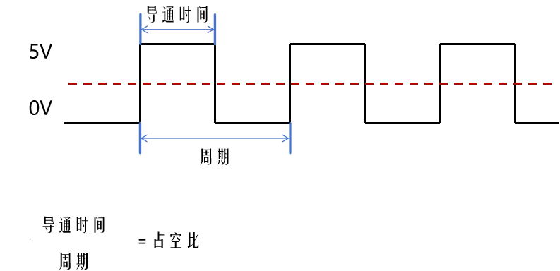
A PWM signal has two core control parameters: period and duty cycle.
3.1 Cycle
Period is the time required for a signal to complete one full waveform cycle; in other words, it is the reciprocal of the signal frequency.

3.2 Duty Cycle
Duty cycle represents the percentage of the period that the signal stays at high level, and is defined as follows:

The shorter the period, the faster the signal switches, and the closer the output effect is to a continuous analog signal.
PWM can control the average output voltage by adjusting the duty cycle.
3.3 Example
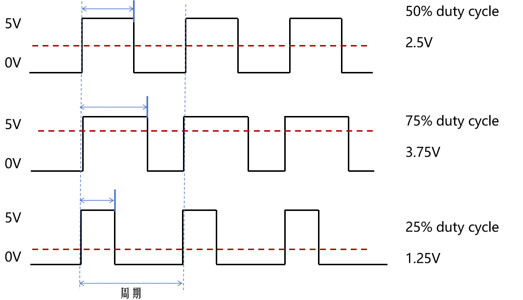
Assume that Vhigh = 5V:
50% duty cycle (high and low levels each account for half): Vavg = 5V x 50% = 2.5V
75% duty cycle (75% high level, 25% low level): Vavg = 5V × 75% = 3.75V
25% duty cycle (25% high level, 75% low level): Vavg = 5V × 25% = 1.25V
The advantages of this technology lie in its ability to effectively control power without the need for complex analog circuits.
Impact on the output effect:
- The shorter the period, the faster the signal switches, and the closer the output effect is to a continuous analog signal.
- Adjusting the duty cycle enables control over the average voltage:
- 0%: Fully extinguished
- 50%: Brightness 50%
- 100%: Fully lit
4. Common hardware structure of PWM signals
This is the general hardware structure diagram of the PWM peripheral, from which we can see exactly how the PWM signal is generated and what processes it goes through.
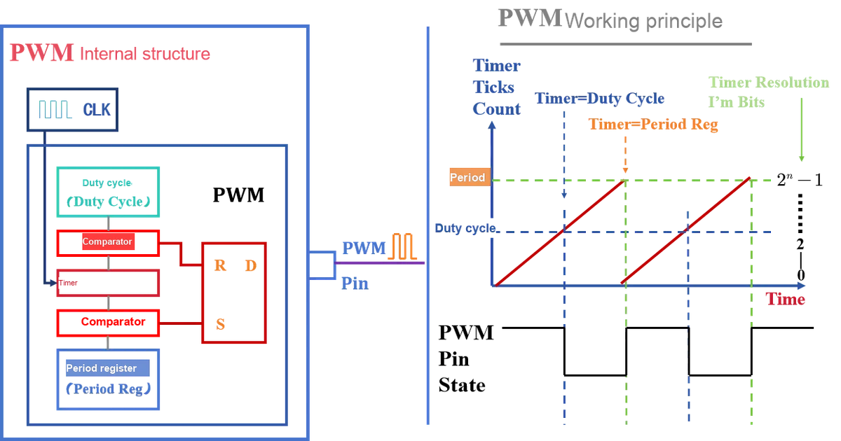
First, the clock source provides a pulse signal to drive the timer to start counting.
The timer starts counting from 0 and increments step by step in accordance with the clock signal.
When the timer count value is compared with the value in the duty cycle register, the first comparator determines the duration of the high level.
When the count value of the timer equals the period register, the second comparator determines whether the PWM signal has completed a full cycle.
Finally, the R-S flip-flop controls the level state of the PWM pin according to the result of the comparator, thereby realizing the switching between high and low levels and generating the PWM signal.
Clock Source: Provides a reference pulse signal.
Timer: Counts based on the clock signal and increments the count value periodically.
Duty Comparator: determines the duration of the high level.
Period Comparator: Determines the end of a cycle and triggers a new cycle.
R-S Flip-Flop (R-S Trigger): Controls the level of the GPIO pin based on the comparator result.
5. analogWrite () function review and supplement
Let's review what we used for our previous analog output simulation: analogWrite () function
Syntax: analogWrite (pin, value);
pin: The GPIO pin that is to output PWM.value: 0~255, corresponding to a duty cycle of 0%~100%.
analogWrite () has default parameters for frequency and resolution:
- Frequency: 1 kHz, which defines the number of cycles the PWM signal completes per second.
- This means that the PWM signal will execute 1000 complete high-low level switching cycles per second.
- resolution: 8-bit, which refers to the degree of subdivision of the duty cycle.
- corresponds to the output value of the PWM signal
valuebeing an integer ranging from 0 to 255.
- corresponds to the output value of the PWM signal
Once the frequency and resolution are fixed, analogWrite () output will have a clear "beat" and "brightness levels", which is equivalent to setting boundaries for the performance range of PWM.
7. LEDC hardware PWM module
" analogWrite () is simple, but it has its limitations. What if we want more precise control? "
In this case, the built-in LEDC hardware PWM module of the ESP32 is required.
7.1 Basic Structure of LEDC
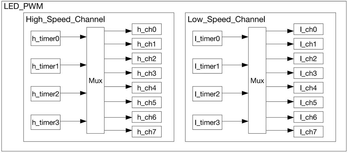
ESP32 provides 16 PWM channels (divided into high-speed channels and low-speed channels), and each channel can be configured with the following settings:
- Frequency (Hz)
- Resolution (bit depth)
- duty cycle
Bind a channel to a specific GPIO pin to output a PWM signal.
7.2 Software Implementation
We use the following: ledcSetup (), ledcAttachPin (), and ledcWrite () functions to achieve PWM signal output.
7.2.1 ledcSetup () function
function prototype
uint32_t ledcSetup(uint8_t channel, double freq, uint8_t resolution_bits);
Functions
Configure the operating parameters (frequency + resolution) of a PWM channel.
Input Parameters
channel(uint8_t): PWM channel number, ranging from 0 to 15.freq(double): Target frequency of the PWM signal (unit: Hz).resolution_bits(uint8_t): resolution bits, range 1~20 bits, which determines the subdivision level of the duty cycle:- 8 bits → duty range: 0~255
- 10-bit → duty cycle range: 0~1023
- 12 bits → duty range: 0~4095
Return Value
(uint32_t), the actually successfully configured frequency.(Because the hardware frequency divider may not be able to precisely match the value set by the user.)
Usage Example
// Configure PWM channel 0, target frequency 5000Hz, 8-bit resolution
uint32_t realFreq = ledcSetup(0, 5000, 8);
Serial.println(realFreq); // Print the actual frequency
7.2.2 ledcAttachPin () function
function prototype
void ledcAttachPin(uint8_t pin, uint8_t channel);
Functions
Bind a specific GPIO pin to the specified PWM channel to output a PWM signal on that pin.
Input Parameters
pin(uint8_t): Target GPIO pin number.channel(uint8_t): The channel number that has been configured vialedcSetup ().
Return Value
void, no return value.
Usage Example
// Bind GPIO 5 to channel 0
ledcAttachPin(5, 0);
7.2.3 ledcWrite () function
function prototype
void ledcWrite(uint8_t channel, uint32_t duty);
Functions
Set the duty cycle of the PWM channel.
Input Parameters
channel(uint8_t): PWM channel number.duty(uint32_t): Duty cycle value, whose range is determined by the resolution:- 8-bit resolution → duty ranges from 0 to 255
- 10-bit resolution → duty value ranges from 0 to 1023
- 12-bit resolution → duty value ranges from 0 to 4095
Return Value
void, no return value.
Usage Example
// Set the duty cycle of channel 0 to 128 (about 50%)
ledcWrite(0, 128);
7.3 Summary of the LEDC Three-Step Method
ledcSetup (): sets the frequency and resolution.ledcAttachPin (): Binds a channel to a specified pin.ledcWrite (): Sets the duty cycle and outputs a PWM signal.
Mnemonic:"Set first → Bind next → Output finally"
8. Summary of This Chapter
In this chapter, we unveil the secret behind analogWrite ()— PWM, Pulse Width Modulation.
- The essence of PWM is not to directly output an analog voltage, but to make the device perceive an "average voltage" by rapidly switching between high and low levels.
- Core Parameters:
- Period (frequency) determines how fast the signal switches.
- Duty cycle determines the average output effect perceived by the device.
- Implementation Principle: The PWM signal is generated by the combined action of hardware units such as clock source, timer, comparator and flip-flop.
analogWrite ()function: On the ESP32, it simulates analog output via PWM, with a default frequency of 1kHz and a resolution of 8 bits (0~255).
To achieve more flexible and precise control, the ESP32 provides LEDC series functions:
ledcSetup (channel, freq, resolution): Configure the frequency and resolution of the channel.ledcAttachPin (pin, channel): Binds the GPIO pin to the specified channel.ledcWrite (channel, duty): Set the PWM duty cycle and output the corresponding signal.
PWM signals are widely applicable in scenarios such as LED dimming, motor speed regulation, and steering gear control. We can regard analogWrite () as an "entry-level interface", while the ledc series functions serve as a "professional toolkit", which can control the frequency, resolution and multiple channels, making them more suitable for practical engineering applications.