
Contents
1. Introduction: How Do Digital Devices Read "Analog Signals"?
As we mentioned earlier: the ESP32 is a digital device, and its CPU, memory, buses, and logic operation units are essentially all digital circuits, which can only process binary 0s and 1s — in other words, it can only determine whether a signal is at a "high level" or a "low level".
But in the last lesson, how exactly did we achieve analog input and output? Doesn't this contradict the digital logic we learned earlier?
Don't worry, this is actually a very representative problem.
In this section, we will unveil the truth behind this mystery.
2. What is an ADC?
Actually, analogRead () is actually driven by a dedicated hardware module inside the ESP32, which is called the ADC (Analog to Digital Converter).
When disassembling the ESP32, we mentioned that "the ADC is a peripheral resource on the ESP32, a hardware module whose function is to convert analog voltage signals into digital signals. "
Its working principle is simple yet crucial: it converts analog signals into digital signals.
When using the ESP32, we default to the following: a high level (3.3V) corresponds to the maximum value 4095, a low level (0V) corresponds to the minimum value 0, and intermediate voltages are linearly mapped to an integer between 0 and 4095, for example:
Analog Voltage Value | integer value |
|---|---|
0V | 0 |
0.8V | 992 |
1.65V | 2048 |
3.1V | 3840 |
3.3V | 4095 |
These integer values are measured in "levels" rather than "volts", and they appear as an integer in the program. When the analogRead () function runs, it automatically calls the ADC, controls the specified pin to perform analog voltage sampling, and returns the converted integer result. This return value can be used for subsequent judgment, calculation or control. (For example, int adc_val = analogRead (pin);), which is the data type that the ESP32 can directly understand and participate in operations with.
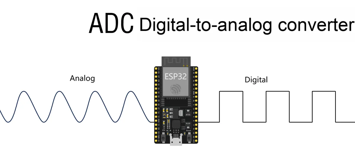
At the code level, analogRead () this function directly invokes the ADC function to realize the input of analog signals.
3. Basic Structure and Conversion Process of ADC
Then, how does an ADC convert analog signals into digital signals? Let’s start with the basic structure of the ADC to find out.
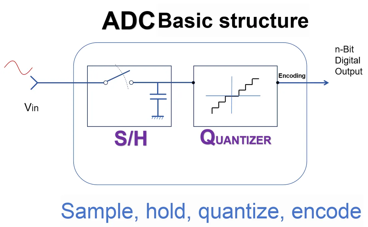
The analog signal (Vin) input to the ADC will first pass through the S/H sample-and-hold circuit, which samples the analog signal at a specific instant and "holds" this signal via a capacitor. Acting like a "pause button", it quickly captures and fixes the instantaneous value of the analog signal to facilitate subsequent processing.
Then, the signal passes through a quantizer, which converts this analog signal into a discrete digital signal.
Finally, the quantized digital signal enters encoding and is converted into a binary digital output that can be processed by the ESP32.
       Analog input voltage (e.g. 1.65V)
                 ↓
     [Sample-and-hold circuit] — captures and stabilizes the voltage value at this instant
                 ↓
          [Quantizer] — sees which segment it falls in (e.g. segment 2048)
                 ↓
          [Encoder] — outputs the digital value 2048 (binary: 100000000000)
To summarize the processing procedure we just went through, it essentially consists of sampling, holding, quantizing, and encoding.
The ADC inside the ESP32 goes through the following hardware modules in sequence during one complete analog signal conversion process:
- Sample and Hold Circuit (S/H)
The function of the sample and hold circuit is to acquire the analog voltage value at the current moment from the input pin, stabilize it, and provide a static input for subsequent processing. This circuit incorporates a capacitor to temporarily "hold" this voltage, preventing it from fluctuating during the conversion process. - Quantizer
Analog voltage varies continuously, while digital systems can only process discrete values with a finite number of levels. A quantizer divides the input voltage into a preset voltage interval according to the resolution of the ADC. For example, a 12-bit ADC divides the input range into 4096 levels, each corresponding to a fixed voltage range. The quantizer determines which level the input voltage falls into. - Encoder
The encoder is responsible for converting the output levels of the quantizer into corresponding binary numbers. For example, if a certain voltage is quantized to the 2048th level, the encoder will output the corresponding binary value100000000000, which is 2048 in decimal.
When an ADC completes one sampling operation, it executes the following steps in sequence: Sampling → Holding → Quantization → Encoding. Finally, the analogRead () function returns the encoded integer value.
4. Basic Characteristic Parameters
The performance and accuracy of an ADC are mainly determined by the following parameters: resolution, reference voltage, and sampling rate. Before using the analogRead () function, we need to understand the meaning and impact of these parameters.
4.1 resolution
Resolution refers to the number of levels into which an ADC can divide an analog voltage signal. The ESP32 uses a 12-bit ADC by default, which means it divides the entire input voltage range into 2¹² = 4096 levels, with a corresponding value range of 0 ~ 4095 — this is also the reason we mentioned earlier that the return value of analogRead () falls within the range of 0 to 4095.
resolution | Number of levels | Voltage step per level (with 3.3V reference voltage) |
4 bits | 16 | 3.3 ÷ 16 = 0.206 V |
10 bits | 1024 | 3.3 ÷ 1024 ≈ 0.00322 V |
12 bits | 4096 | 3.3 ÷ 4096 ≈ 0.000805 V |
Assume that the analog input voltage range of the ADC is from 0V to 3.3V
If the resolution is 4 bits, the range of 0-3.3V will be divided into 15 discrete voltage levels ranging from 0000 (0) to 1111 (16)
With a resolution of 12 bits, the range of 0 to 3.3V is divided into 4095 discrete voltage levels ranging from 000000000000 (0) to 111111111111 (4096)
The higher the resolution, the finer the voltage division, and the smaller voltage changes that can be captured. However, the overhead of data processing will also increase accordingly.
4.2 Reference Voltage - Vref
The reference voltage determines the maximum value of the analog input voltage that the ADC can process.
- If the reference voltage is set to 3.3V, then the ADC can acquire voltages within the range of 0V ~ 3.3V.
- If the reference voltage is set to 1.1 V, any input exceeding 1.1 V will be clipped to the maximum value (i. e., 4095) and thus fail to reflect the actual voltage.
Assume that a 12-bit ADC with Vref = 3.3V is used:
- The voltage interval represented by each level is 3.3 ÷ 4096 ≈ 0.000805V
- If the input voltage is 1.65V:
1.65 ÷ 3.3 × 4095 ≈ 2047- The ADC output value is approximately 2047
In addition, it should be noted here that the input analog voltage value should always be lower than the reference voltage value, and the reference voltage value should always be lower than the operating voltage value of the microcontroller.
In other words, the reference voltage shall meet two requirements:
- Input voltage ≤ Vref
- Vref ≤ MCU supply voltage (typically 3.3V)
4.3 Sampling Rate
Sampling rate refers to the number of times an ADC can acquire data per second. A higher sampling rate means more frequent data collection per unit time and a faster system response, making it suitable for application scenarios that require real-time monitoring (such as audio input, motion detection, etc.).
The maximum sampling rate of the ADC of the ESP32 is approximately 6,000 ~ 18,000 samples per second (the specific value depends on the CPU frequency and ADC configuration).
5. ADC on ESP32
The ESP32 has two built-in 12-bit ADCs, namely ADC1 and ADC2, and each module supports multiple analog input channels.
5.1 Two ADC Modules: ADC1 and ADC2
It should be noted that not all pins support analog input. As can be seen from the pinout diagram, only the following GPIOs that are hardware-connected to the ADC module can be used for analogRead (): we can read analog signals from 16 different GPIO pins.
- ADC1: Contains 8 channels, corresponding to GPIO 32 to 39.
- ADC2: Contains 10 channels, namely GPIO 0,2, 4,12 ~ 15,25 ~ 27.
There are obvious differences between the two in terms of usage:
Module | Available GPIO pins | Description of Features |
ADC1 | GPIO 32 ~ 39 | Recommended for use, as it offers better stability |
ADC2 | GPIO 0, 2, 4, 12-15, 25-27 | Shares hardware resources with the Wi-Fi module, with limitations |
These pins can be connected to several sensors, and by using the analogRead () function, we can read the digital values of these analog signals.
5.2 Conflict with Wi-Fi: Limitations of ADC2
However, it should be noted that not all pins support analog input, and only these specific 16 GPIO pins can be used for analog input via the analogRead () function.
When in use, it should also be noted that: when Wi-Fi is enabled, ADC2 is occupied and unavailable, so you can only rely on ADC1.
In addition, all ADC types of the ESP32 are successive approximation register (SAR) ADCs.
5.3 ADC Types
The ESP32 integrates two 12-bit Successive Approximation Register (SAR) ADCs, which continuously adjust and compare the input signal against a set of predefined quantization values through a successive approximation process.
Successive approximation means that instead of testing one by one, it narrows down the scope step by step just like "binary search" until the closest value is found.
The process is roughly as follows (taking a 12-bit ADC as an example):
- First, assume that the most significant bit is 1 (for example, 1000 0000 0000), and compare the corresponding voltage value with the input signal.
- If the assumed value is greater than the input → change this bit back to 0.
If the assumed value is smaller than the input → keep it as 1. - Then test the next one (0100 0000 0000), make a comparison again, and so on.
- By making a total of 12 comparisons in this way, a 12-bit binary result can be obtained.
Key Points:
- SAR ADC does not work by "comparing each individual quantized value one by one"; instead, it determines one bit at a time and gradually narrows down the range.
- The end result is just like playing the game "Twenty Questions": you answer "higher or lower" each time, and finally you get a precise answer.
6. Summary of This Chapter
In this chapter, we uncover the secret behind analogRead ()— the built-in ADC (Analog-to-Digital Converter) of the ESP32. It converts voltage signals into digital values, enabling the digital device ESP32 to perceive the analog world.
The core process of ADC is: Sampling → Holding → Quantization → Encoding, which ultimately maps the voltage in the range of 0-3.3V to integers ranging from 0 to 4095.
Key Features:
- resolution: determines the level of detail (12 bits → 0~4095).
- Reference voltage: determines the voltage measurement range.
- Sampling rate: Determines the sampling speed.
The ESP32 features ADC1 (recommended for use) and ADC2 (conflicts with Wi-Fi). It operates on the Successive Approximation Register (SAR) principle, which works like a binary search to gradually zero in on the target value and deliver results rapidly.
👉 One-sentence summary: analogRead ()= analog voltage → digital value → something the ESP32 can understand and process.