
Contents
1. Introduction: Beyond On and Off
In previous tutorials, we have used GPIO to control the on/off of LEDs and read the status of buttons — these operations are quite straightforward: they only have two states: either on or off. This is what we call digital input/output (Digital I/O).
In reality, however, control is not always as simple as being either "on" or "off"; many things are inherently continuously varying, for example:
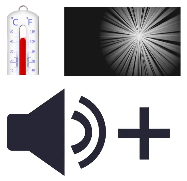
- The temperature does not jump from 20°C to 30°C all at once; instead, it rises gradually.
- Light does not follow a strict black-or-white dichotomy, but transitions gradually from darkness to brightness;
- Volume is not just either loud or muted; it is adjustable.
These "intermediate states" require us to use GPIO to process analog signals. This is exactly what we will learn in this chapter:
Don't worry, although the word "analog" sounds complicated, it essentially means — that instead of being limited to just 0 and 1, there can be "intermediate values" between 0 and 1, thus enabling smoother and more nuanced control.
2. Digital Signals and Analog Signals
Do you know the difference between digital signals and analog signals?
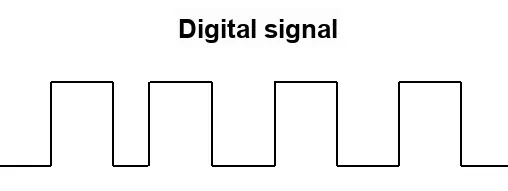
In the ESP32, digital signals have only two states: high level (1) and low level (0), which are discrete and can only switch between these two states.
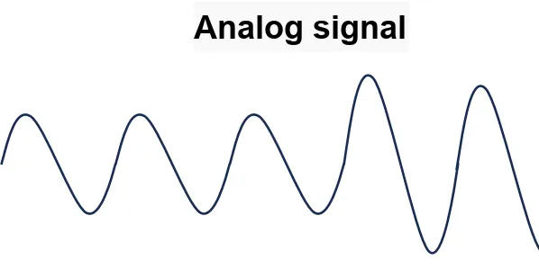
An analog signal is a continuous voltage signal that can take any value within a specific range, not just two fixed states, which is why analog input and output can operate between the on and off states.

3. Analog Input and Analog Output
So how does the ESP32 process these analog signals? There are mainly two approaches: analog input and analog output.
In this section, we will not delve into circuit principles, nor will we dig deep into the working mechanisms of ADC or PWM. Instead, from a software perspective, we will take a look at how they are used and what effects they produce.
Implementing analog output and analog input is actually very straightforward; you can directly call analogWrite () and analogRead () these two functions to get it done.
3.1 Analog Input
In reality, there are many "variable" devices, such as potentiometers, photoresistors, temperature sensors, and so on. Their voltage does not stay fixed at a certain value, but changes gradually with the surrounding environment.
To be able to "read" these constantly changing analog signals, we need to use analogRead () function to read the analog voltage value on a specific GPIO pin.
Let's take a look at the function prototype of the analog input function:
int analogRead(uint8_t pin);- Input Parameter
pin: The GPIO pin number to be read (must be a GPIO pin of ESP32 that supports ADC) - Return Value
- Type: int (integer)
- Range: Default 0 ~ 4095 (12-bit ADC resolution)
0→ Voltage = 0V4095→ Voltage ≈ 3.3V (reference voltage)
As for how to use this function specifically, let's look at the following line of code:
int val = analogRead(34); // Read the voltage on GPIO34This line analogRead (34) means: read the voltage value on GPIO34, and the result will be stored in digital form in the variable val.
This val value represents the analog signal strength you read, which generally ranges from 0 to 4095, corresponding to a voltage variation from 0V to 3.3V. That is to say: when the voltage is 0V, the reading is 0; when the voltage is 3.3V, the reading is 4095. Voltages in between will be converted to corresponding intermediate values — for example, 1.65V corresponds to approximately 2048, rather than being a single low level 0 or high level 1.
You can print it out like this to have a look:
Serial.println(val);Suppose you connect a potentiometer to GPIO34: as you turn the , the values printed on the screen will change accordingly, such as 89,1532,3821.. .
These variations represent the "magnitude" of analog signals.
So, analogRead () helps the ESP32 sense *how much* a change is, not just *whether* a change exists. This is what we call analog input.
3.2 Analog Output
Conversely, if we want the ESP32 to output a control signal (such as making the LED brighter and then even brighter), we can use the function analogWrite () to achieve the analog output effect.
Let's first take a look at the function prototype of the analog input function:
void analogWrite(uint8_t pin, int value);- Input Parameters
pin- Output pin number
- PWM-capable pins on ESP32
value- The duty cycle to be output (i. e., brightness, intensity)
- Range: 0 ~ 255
0→ 0% duty cycle (fully off)255→ 100% duty cycle (fully open)
- Return value: None
For example, the following line of code:
analogWrite(5, 128);  // Output a medium-strength control signal to GPIO5
// analogWrite(pin number, output value);
// First parameter: the GPIO pin number to output the signal on
// Second parameter: output strength, range 0 to 255
output value | Effect |
|---|---|
0 | The weakest, e. g., the LED does not light up at all |
128 | Medium intensity, such as half brightness of LED |
255 | the strongest, e. g. the brightest LED |
Then the meaning of this line of code is: we want the GPIO5 pin to output a brightness, speed or volume that is half of the high-level state.
You can try writing it like this:
analogWrite(5, 0);    // LED off
analogWrite(5, 64);
analogWrite(5, 128);  // LED half brightness
analogWrite(5, 192);
analogWrite(5, 255);  // LED full brightness
You’ll find that LEDs are no longer just “on” or “off” — instead, they can be “a bit brighter”, “even brighter”, “very bright”. .. With these “intermediate states”, we can continuously adjust the second parameter to make the LED fade in and fade out, or control the motor to run slower or faster.
4. Experimental Verification Section
Now, let's verify the functions of analog input and analog output in person through several simple experiments.
Hopefully this experiment can also help you understand that:
- What is an analog input (potentiometer/joystick → voltage → analog value)
- What is analog output (analog value → voltage → LED brightness)
In these experiments, we will use the following electronic components: potentiometers, input joysticks, regular LEDs, and RGB color LEDs. We will explain each of them one by one, except for the regular LEDs that we have used before.
4.1 Rotating Potentiometer Experiment: Reading Voltage Changes
Through this experiment, we will understand the basic principle of "analog input": to read a changing value, rather than just 0 and 1.
4.1.1 Experimental Objectives
The goal of this experiment is to let you experience firsthand how analog input works. Through hands-on practice, we will master:
- How to connect a potentiometer to the ESP32
- How to use
analogRead ()to read analog voltage values - How to check voltage changes via the serial monitor
👉 "Turn the → voltage changes → ESP32 reads the value → displayed via serial port"
4.1.2 Rotary Potentiometer
Actually, a potentiometer is essentially a variable resistor. For the potentiometer shown in the figure, turning the adjusts the position of the sliding contact on the resistive strip, thereby changing the resistance value. This varying resistance value will affect the output voltage.
4.1.3 Circuit Connection
A rotary potentiometer has three pins:
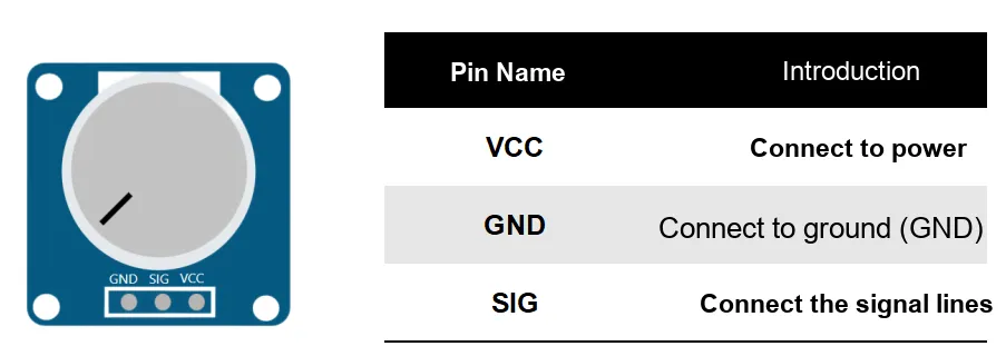
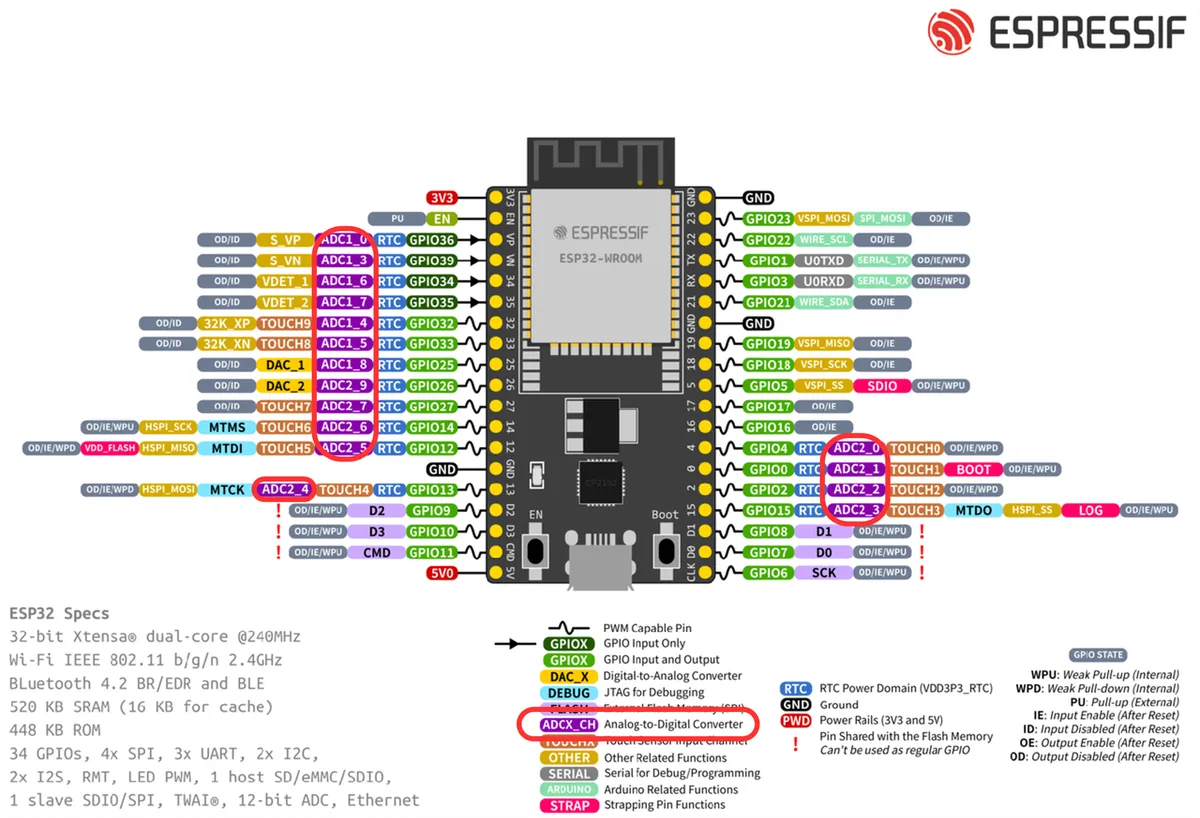
Note: Not all pins on the ESP32 support analog input. You need to select a pin that supports ADC analog input according to the pinout diagram and connect it to the SIG pin (the part marked by the red box).
4.1.4 Sample Code
We use analogRead () to read the value of this output voltage, which might be 356,1234,3890, and so on. These values indirectly tell us how far the has been turned.
10-1 Rotary Potentiometer Experiment - Wokwi ESP32, STM32, Arduino Simulator
void setup() {
  Serial.begin(115200);           // Initialize serial communication
}

void loop() {
  int val = analogRead(34);       // Read the voltage on GPIO34
  Serial.println(val);            // Print the result to the serial monitor
  delay(200);                     // Short delay to avoid scrolling too fast
}
Run the code, and when we turn the , the position of the sliding contact on the resistive strip changes, which alters the resistance value and consequently changes the intermediate output voltage. We will see a string of values continuously scrolling on the screen:
67
135
278
980
2048
3900
These numbers are the "analog voltage values" after ADC conversion, ranging from 0 to 4095, which corresponds to a voltage range of 0 to 3.3V.
- When the is turned to the far left, close to 0V → the output is close to 0;
- When turned to the far right and approaching 3.3V, the output will be close to 4095;
- The rotation angle in the middle → the output value varies between these two.
This means that the ESP32 has successfully read the "analog" voltage value through the GPIO34 pin, rather than a simple on or off state.
4.2 Sliding Potentiometer Experiment
4.2.1 Experimental Purpose
Through this experiment, we will:
- Understand the structure and working principle of the sliding potentiometer
- Use
analogRead ()to obtain the analog voltage corresponding to the slider position - Observe the numerical changes in real time in the serial monitor.
👉 "Slide the push rod → Voltage change → ESP32 reads → Value display"
4.2.2 Slide Potentiometer
Essentially, a slide potentiometer is the same component as a rotary potentiometer, both being variable resistors. The only difference is that a slide potentiometer operates not by rotation, but by pushing or pulling a sliding rod, making it more suitable for intuitive adjustment applications such as volume sliders, light dimmers and the like.
4.2.3 Circuit Connection
It also has three pins, and the connection method is the same as that of the rotary potentiometer:
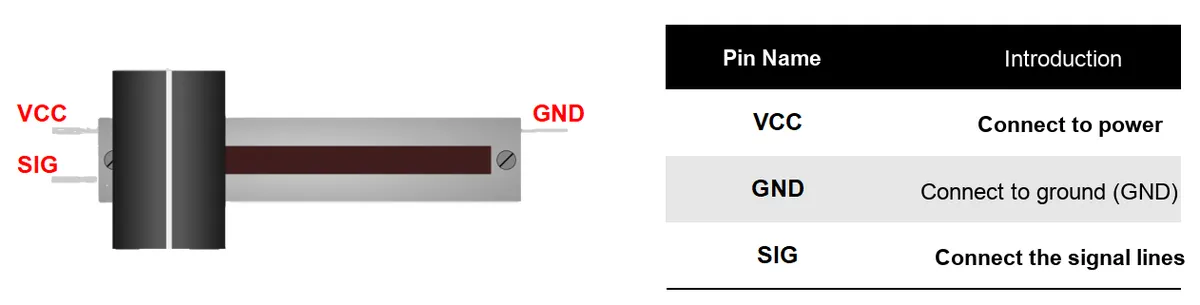
Note: Just like with a rotary potentiometer, you need to select a pin on the ESP32 that supports analog output to connect to the SIG pin!
4.2.4 Sample Code
The code is almost identical to that of the rotary potentiometer experiment; the only difference lies in the input device, and you can still use analogRead () to read the voltage changes.
void setup() {
  Serial.begin(115200);           // Initialize serial
}

void loop() {
  int val = analogRead(34);       // Read the voltage of the slide potentiometer
  Serial.println(val);            // Print the value
  delay(200);                     // Wait a moment, don't refresh too fast
}
This code is exactly the same as the previous one — because you are still using analogRead (). Once you replace the connected device, you will see the new input effect.
If you push the slider from left to right, you will see the value output by the serial port increase gradually, for example:
86
159
623
2034
3840
Doesn't it look exactly like a Progress Bar? When you drag the slider, you will see the numbers printed on the screen change accordingly:
- Slide the slider to one end → the value approaches 0
- Scroll to the middle → approx. 2000
- Push to the other end → Approaching 4095
This change process is continuous, which is very suitable for control interfaces, such as adjusting the volume and adjusting the brightness of lights.
4.3 Input Joystick Experiment
We have all played with and sliders, which can sense changes in one direction. But what if we want to sense two directions at the same time? This is where the joystick module comes in handy — it is essentially a two-dimensional controller made by combining two sliding potentiometers.
4.3.1 Experimental Purpose
Through this experiment, we will learn to:
- Understand the structure and working principle of the joystick module
- Use
analogRead ()to read the analog signals in both X and Y directions simultaneously - Observe the value changes corresponding to the push-pull direction of the joystick via the serial port
In a nutshell: Push the joystick → X/Y voltage changes → ESP32 reads the data
4.3.2 Input Joystick
A joystick module generally consists of a circular joystick and a base, and the joystick can be moved up, down, left and right. It is commonly used for direction control, such as controlling the movement of a character in a game.
The interior of the joystick module typically includes:
- Two sliding potentiometers: one for controlling the X direction (left-right), and the other for the Y direction (up-down);
- A push switch (on some models): Pressing the joystick triggers a digital signal switch, similar to a button;
4.3.3 Circuit Connection
Joystick modules typically have the following pins:
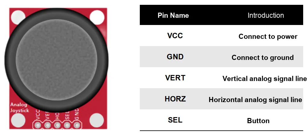
In this experiment, we use HORZ and VERT two pins to read the direction changes of the joystick.
4.3.4 Sample Code
Here is all of our code:
void setup() {
  Serial.begin(115200);   // Initialize serial
}

void loop() {
  int xVal = analogRead(34);  // Read X direction
  int yVal = analogRead(35);  // Read Y direction

  Serial.print("X轴:");
  Serial.print(xVal);
  Serial.print("  |  Y轴:");
  Serial.println(yVal);

  delay(200); // Refresh interval
}
The range of analog values of the joystick we read is:
          Y轴
      Push forward ↑ 0 (middle value)
          ||
0 ←Push left--[Origin]--Push right→ 4095 X-axis
          ||
      Push back ↓ 4095
Essentially, a joystick module is a combination of two sliding potentiometers, which can read "analog" signals in two directions respectively via analogRead (), and it enables 2D position control with simple push-pull operations, making it ideal for game controllers, vehicle direction control and other such applications.
4.4 RGB Color Light Experiment
4.4.1 Experimental Objectives
Through this experiment, you will learn how to:
- Understand the basic structure and color principle of RGB color string lights
- Use
analogWrite ()to control the brightness of the red, green and blue channels respectively - Achieve color mixing to create your favorite light
In a nutshell: Three colors, three lines of code, and endless lighting variations!
4.4.2 RGB Color Light
An RGB color light may look like an ordinary LED, but in fact, there are three tiny light-emitting bulbs hidden inside it, which emit red, green and blue light respectively. When these three colors are combined together, they can produce a huge variety of colors, for example:
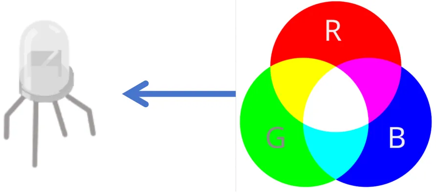
- Red + Green = Yellow
- Red + Blue = Magenta
- Green + Blue = Cyan
- Red + Green + Blue = White
4.4.3 Circuit Connection
Most RGB LED strips have 4 pins, which are as follows:
Pin Function | Description |
|---|---|
R (Red) | Control the brightness of the red light |
G (Green) | Control the brightness of the green light |
B (Blue) | Control the brightness of blue light |
Common pin (usually marked as "negative" or "positive") | The common power supply path is divided into two types: common cathode and common anode. |
You only need to use analogWrite () to output custom analog values to the three pins R, G, and B to control the color, for example:
//0-255
analogWrite(redPin, 255);   // Red at full brightness
analogWrite(greenPin, 0);   // Green off
analogWrite(bluePin, 128);  // Blue at half brightness
By adjusting the values of the three analog outputs, you can tune to almost any color you can think of.
4.2.4 Sample Code
We control the RGB light to sequentially display the three solid colors red, green and blue every 1 second, and finally mix them into white light.
void setup() {
  // Set pin as output
  pinMode(16, OUTPUT); // Red
  pinMode(17, OUTPUT); // Green
  pinMode(18, OUTPUT); // Blue
}

void loop() {
  // Red
  analogWrite(16, 255);
  analogWrite(17, 0);
  analogWrite(18, 0);
  delay(1000);

  // Green
  analogWrite(16, 0);
  analogWrite(17, 255);
  analogWrite(18, 0);
  delay(1000);

  // Blue
  analogWrite(16, 0);
  analogWrite(17, 0);
  analogWrite(18, 255);
  delay(1000);

  // Mixed into white
  analogWrite(16, 255);
  analogWrite(17, 255);
  analogWrite(18, 255);
  delay(1000);
}
You can freely modify the value of analogWrite (), for example:
analogWrite(16, 128); // Red at half brightness
analogWrite(17, 64);  // Green slightly dim
analogWrite(18, 200); // Blue fairly bright
This way, you can achieve various effects such as lavender, sky blue, orange, pink and more.
An RGB color light is a combination of three LEDs. By adjusting the brightness of each channel, we can synthesize almost all colors, which serves as one of the most vivid and intuitive examples of analog output.
5. Summary of This Chapter
In this chapter, we have moved from the digital world of "on and off" to the analog world of "gradual change".
- Digital I/O: only 0 and 1, representing "presence or absence".
- Analog I/O: capable of representing intermediate states, indicating "how much".
ESP32 provides two key capabilities:
- Analog Input (analogRead)
- Convert externally continuously varying voltage signals (such as those from potentiometers and analog joysticks) into digital values.
- Reading range: 0 ~ 4095 (corresponding to 0V ~ 3.3V).
- Enable the ESP32 to "perceive the magnitude of changes".
- Analog Output (analogWrite)
analogWrite ()divides the output into 256 levels ranging from 0 to 255.- 0 gear: Fully off (e. g. LED turns off).
- 255 levels: Fully open (e. g. at maximum brightness for an LED).
- Intermediate gear: represents different levels of brightness/intensity.
In the experimental section, we verified these concepts in sequence:
- / slide potentiometers → Intuitive feedback for analog inputs;
- Joystick module → application of dual-channel analog input;
- RGB color string lights → A colorful world brought by three-channel analog output.