
Contents
1. Introduction
In embedded programming, we often encounter such a problem: how to make a program execute certain tasks at fixed time intervals? For example, collecting sensor data once every second.
Many beginners tend to add a loop () with a delay (1000) inside to implement periodic execution of tasks. While it seems to work on the surface, this approach is actually blocking — when delay () is called, the CPU pauses completely during the waiting period, causing all other tasks to get "stuck" until the delay duration elapses.
To solve this problem, we can use a Timer — which automatically triggers when the set time interval elapses, allowing the CPU to handle other tasks during the waiting period instead of getting stuck on delay ().
In this way, we will neither waste resources nor easily miss important events.
2.3 Timer Interrupt.xmind 78 KB
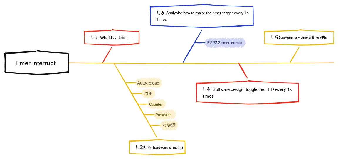
2. Timer Interrupt
2.1 What is a Timer
A timer is a hardware module used to generate precise time intervals, execute periodic tasks or trigger interrupts. Built into the ESP32 chip, it can count independently while the CPU is processing other tasks without affecting the normal execution of those tasks.
2.2 Relationship Between Timer Interrupt and Main Loop
In embedded systems, the main loop of the CPU is usually responsible for continuously polling and executing various tasks, such as reading sensors, processing data, and refreshing displays. If we use the blocking delay () function to implement periodic operations, the CPU will be unable to process other tasks during the waiting period, which reduces the efficiency of the entire system. The advantage of the timer is that it can work in parallel with the CPU's main loop to achieve independent counting and triggering.
A timer can count time independently while the CPU is executing the main loop, without requiring the CPU to actively check the time. When the count reaches the set value, the timer notifies the CPU via an interrupt to execute the specified task, which means the CPU can continue executing other logic while waiting for the timer to trigger, instead of being "stuck". This non-blocking feature enables the system to handle multiple tasks simultaneously, improving response speed and real-time performance.
In practical applications, timers and the main loop usually work in a cooperative mode. The timer is responsible for accurate timing and interrupt triggering, while the specific task logic is handled by the main loop or other tasks. Through this division of labor, the timer provides a precise time reference, and the main loop maintains flexibility and efficiency. The two complement each other, enabling embedded systems to execute periodic tasks efficiently and stably.
2.3 Basic Hardware Structure of Timer
As far as a timer is concerned, we definitely need to know some of its basic parameters such as the counting range and the counting frequency.
To find the answer from the hardware structure, the basic hardware structure of the timer consists of the following parts:
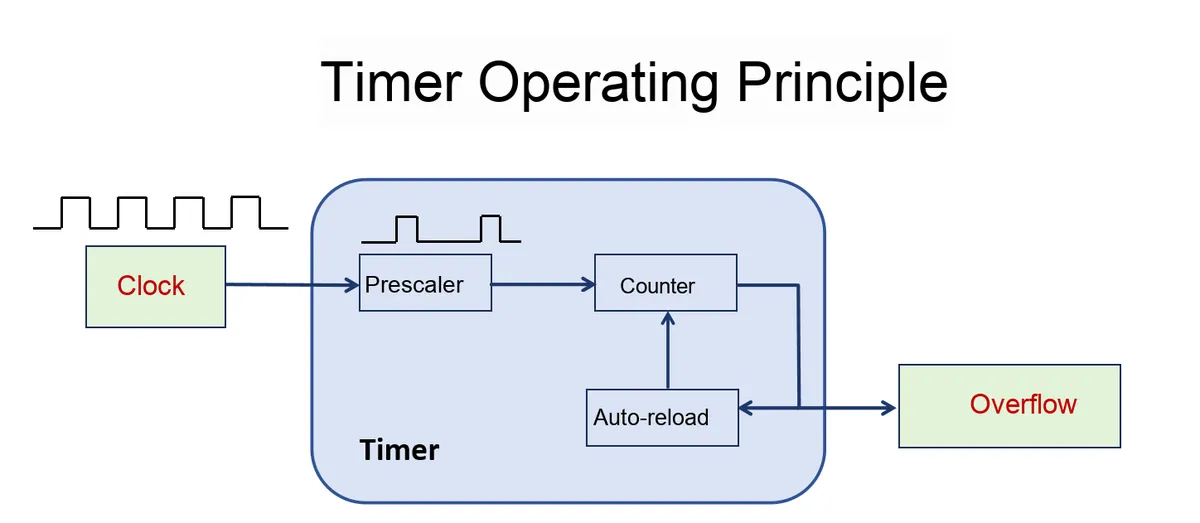
The core of a timer lies in its reliance on clock signals for timing. A clock signal is a stable square wave signal whose frequency determines the counting speed of the timer, which measures time by counting these clock pulses. When the count reaches a preset value, the timer triggers an interrupt or performs the corresponding operation.
To accommodate different timing requirements, timers are usually equipped with frequency dividers. A frequency divider can scale down the original clock frequency by a certain factor, slowing down the timer's counting process and thus extending its period. For example, if the system crystal oscillator frequency is 80 MHz, setting the frequency divider to 80 will reduce the timer's counting frequency to 1 MHz, meaning each count corresponds to a time interval of 1 microsecond. By adjusting the frequency division coefficient and the values of the counter, the timer's period can be precisely controlled, enabling time management ranging from microseconds to seconds.
The settings of clock frequency and frequency division coefficient not only determine the cycle length of the timer, but also directly affect the timing accuracy and resolution. Accuracy refers to the minimum time unit that the timer can measure, while resolution depends on the counting bit width of the timer and determines the maximum representable time range. In practical applications, it is crucial to understand the relationship between clock frequency and frequency division, so as to correctly set the timer cycle, avoid accumulated errors, and ensure the accurate execution of periodic tasks.
2.4 Timer Resources of ESP32
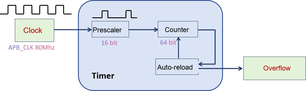
The ESP32 microcontroller integrates 4 built-in 64-bit general-purpose timers, which feature high flexibility and powerful functions. Each timer is equipped with a 16-bit prescaler and a 64-bit auto-reload counter. These timers are divided into 2 groups, each containing 2 timers, which are named TIMGn_Tx, where n denotes the group number and x denotes the timer number.
2.4.1 Clock Source
The clock source is responsible for providing a stable clock signal, which is the core of timer counting. The clock signal is a stable square wave signal, and its frequency determines the counting speed of the timer.
- Higher clock frequency → higher timing accuracy
- Lower clock frequency → longer timing duration
The default input clock source for the general-purpose timers of the ESP32 is the APB bus clock (APB Clock). This clock has a fixed frequency of 80 MHz, which is derived by frequency division from the system main clock. When using 80 MHz as the reference, the timer can achieve a theoretical timing 12.5 ns resolution, thus supporting high-precision applications. It should be noted that a higher frequency means faster counter overflow, so in practical applications we often adjust it in combination with a prescaler to strike a balance between timing accuracy and time span.
Overall, the clock source serves as the upstream input of the entire timer chain: it first passes through the prescaler and then enters the counting unit, thereby implementing various timing and counting functions.
Source: The ESP32 timer uses the APB clock (typically 80 MHz) as its input.
Function: It provides the base frequency, serving as the "heartbeat" for the timer to operate.
Key points: Users cannot directly change the APB frequency, but can adjust the output frequency via the subsequent prescaler.
2.4.2 Prescaler
The prescaler is responsible for frequency division of the input clock signal, which is used to adjust the input clock frequency and reduce the speed of the counter.
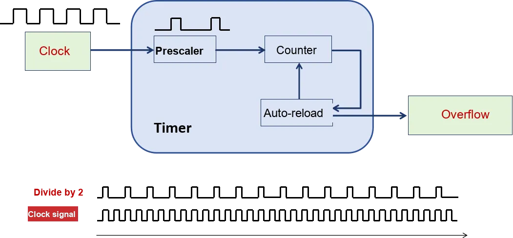
The prescaler of the ESP32 is 16-bit, and a 16-bit prescaler allows us to set the frequency division coefficient (N) in the range of 0 to 65535 (i. e., 2^16 − 1), which corresponds to an actual frequency division range of 2 to 65536.
Then, the actual counting frequency of the timer can be calculated using the following formula:
Counter clock = Main clock / Frequency division coefficient N
When taking the 80 MHz main clock as the reference, for example:
- Frequency division by 2 (prescaler N = 2)
- Actual frequency division coefficient = 2
- Actual counting frequency of the timer = 80 MHz ÷ 2 = 40 MHz
- Counting rule: The counter increments once for every 2 main clock pulses that elapse
- Time interval: The counter increments by 1 every 1 ÷ 40,000,000 s = 25 ns
- Divide-by-8 Frequency Division (Prescaler N = 8)
- Actual frequency division coefficient = 8
- The actual counting frequency of the timer = 80 MHz ÷ 8 = 10 MHz
- Counting rule: The counter increments by 1 every time 8 main clock pulses elapse
- Time interval: The counter increments by 1 every 1 ÷ 10,000,000 s = 100 ns
- Divide-by-80 (prescaler N = 80)
- Actual frequency division coefficient = 80
- Actual counting frequency of the timer = 80 MHz ÷ 80 = 1 MHz
- Counting rule: The counter increments by 1 once for every 80 main clock pulses.
- Time interval: The counter increments by 1 every 1 ÷ 1,000,000 s = 1 μs
In this way, we can strike a balance between high precision (e. g., microsecond-level timing) and long time spans (e. g., second-level or minute-level timing). Proper use of the prescaler can not only prevent the counter from overflowing too quickly, but also obtain sufficient time resolution when needed.
2.4.3 Counter
Inside a timer, the counter is the core component, which is used to accumulate the clock pulses that have passed through the prescaler. Whenever the counter receives a clock pulse, it starts counting, i. e., incrementing or decrementing. The timer counter of the ESP32 supports up counting and down counting two modes, which users can configure during initialization.
The counter of the ESP32 timer is 64-bit, which means its counting range is from 0 to 18,446,744,073,709,552,000 (i. e., 2^64 − 1).
In the up-counting mode, the counter value increments from 0 until it reaches the set threshold or overflows; in the down-counting mode, by contrast, it decrements stepwise from the set value down to 0. When the counter hits the target value, it can trigger an alarm event or an interrupt, thereby enabling precise timing control.
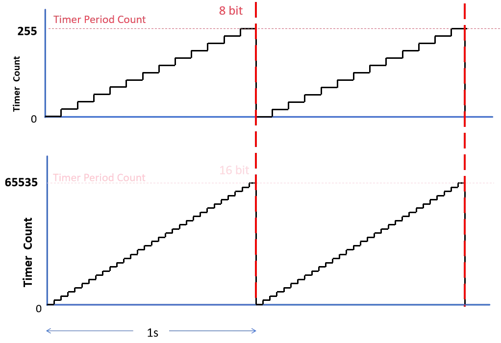
Combined with the prescaler configuration described earlier, the counter increments by 1 each time it receives a divided pulse. By adjusting the prescaler and the maximum value of the counter, we can precisely control the timer period. For example, if the prescaler is set to 80 to make the counter frequency 1 MHz (incrementing by 1 every microsecond), then setting the counter to 1,000,000 will achieve a 1-second timing period. This design makes the timer both flexible and high-precision, capable of meeting the timing requirements of various embedded systems.
Core component: a counter, which is used to increment (or decrement) the clock pulses output by the prescaler.
Operation Mode:
- Count up (default): 0 → Alarm Value.
- Count down: Alarm Value → 0.
Significance: Counter value — reflects the elapsed time duration via the accumulated pulse count.
2.4.4 Overflow
After counting for a period of time, the counter will overflow once the count value reaches its maximum limit, which further triggers an interrupt to indicate the end of a timing cycle. The overflow mechanism serves as a critical foundation for timers to implement periodic tasks, enabling the system to respond in a timely manner or execute the next operation.
2.4.5 Auto-reload
Auto-reload means that when the counter overflows, it will be automatically reset to the initial value to start a new counting cycle. This function can be configured via software:
- If you need periodic tasks, enable auto-reload to make the timer count cyclically;
- If only a single timing event is required, disable auto-reload, and the counter will stop after completing one counting cycle.
Through automatic reload, the timer can continuously perform repetitive tasks without manual intervention, thus realizing a stable cyclic timing function.
3. Implementation Process of Timer Interrupt
3.1 Requirements Analysis
In this example, we aim to implement a function that makes the LED blink once every 1 second. This is a typical periodic task that requires a timer to trigger events at fixed intervals. To ensure the stability and responsiveness of the system, we require the blinking operation to be non-blocking, which means the LED blinking must not prevent the main loop (loop) from executing other tasks.
Through this example, we will learn the configuration and interrupt mechanism of the hardware timer, covering the whole process from parameter selection, ISR writing to timer startup and task execution. We mainly need to confirm three key points:
- Functional Objective: The LED toggles its state every 1 second to achieve a blinking effect.
- Time requirement: The fixed cycle is 1 second to ensure a stable flashing interval.
- System requirements: The LED blinking task shall not block the main loop, and other tasks are allowed to be executed in parallel.
3.2 Hardware Connection
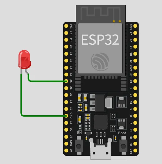
3.3 Selection of Timer Parameters
When implementing the function of making an LED blink per second, it is first necessary to reasonably select the parameters of the timer to ensure that the timer can trigger interrupts at precise time intervals. The timer of the ESP32 can be configured via the clock source, prescaler, counter initial value and alarm value to achieve precise time control.
Our goal is to trigger an interrupt once every 1 second, so the period of the timer should be set to 1 second. The length of the period is determined jointly by the counter frequency and the alarm value. With the formula:
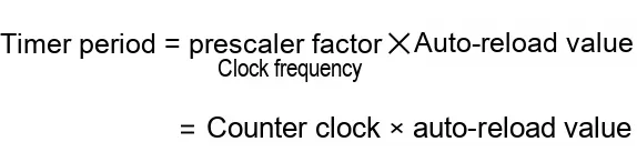
We can see the relationship among the auto-reload value, prescaler coefficient, clock frequency and timer period of the timer.
Assuming the default main clock frequency of ESP32 is 80 MHz and the target period is 1 second, the known parameters are as follows:
- Target Period: 1 second
- Clock Frequency: 80 MHz
The unknown parameters are the prescaler coefficient and the auto-reload value.
3.3.1 Prescaler Factor - prescale
The actual counting frequency of the timer can be calculated using the following formula:
Counter clock frequency = Main clock frequency / Prescaler coefficient (N)
For the convenience of calculation, we choose N = 8000, which means that the counter increments once every 8000 main clock pulses. The actual counting frequency of the timer = 80 MHz ÷ 8000 = 10 kHz, that is, it increments by 1 every 0.0001 s = 100 μs.
3.3.2 Auto-reload Value - alarm_value
Once the prescaler is determined, the counting frequency of the timer is fixed. Next, we need to calculate the auto-reload value (Alarm Value), which determines how many counting cycles the timer goes through before triggering an interrupt.

The counter starts accumulating from 0, and an interrupt is triggered when the counter value reaches the auto-reload value. Since we expect a period of 1 second, the auto-reload value is 10000.
Finally, we also need to check whether the auto-reload value falls within the counting range of the counter. The counting range of a 64-bit counter is from 0 to 18,446,744,073,709,552,000 (i. e., 2^64 − 1), so 9,999 is obviously a valid value.
3.3.3 Final Parameters
The final parameters we obtained are as follows:
- Prescaler: 8000
- Auto-reload value: 10000
3.4 Software Code Writing: Control the LED to toggle once every 1 second
Step 1: Define global variables
// Hardware configuration
#define LED_PIN     21   // GPIO pin the LED is connected to
#define TIMER_NUM   0    // Timer number used (0-3)
#define PRESCALER   8000 // Prescaler value (already calculated)
#define ARR_VALUE   9999 // Auto-reload value (already calculated)
Step 2: Timer Device Configuration
hw_timer_t *My_timer = NULL; // Timer handle (pointer initialized to null)Create a pointer of type hw_timer_t named My_timer for timer configuration.
hw_timer_t What is it?
In the ESP32 Arduino framework, hw_timer_t is a struct type used to describe all configuration information of the hardware timer, such as:
- Timer number (0~3)
- Divider Value (divider)
- Counting Mode (Up/Down)
- Interrupt Trigger Condition (Alarm Value)
*My_timer
- In
hw_timer_t *My_timer, an extra*is added, which indicates that this is a pointer to the hw_timer_t type. - It does not directly store the timer itself, but rather stores "the address of the timer object in memory".
The benefits of doing this are as follows:
- The ESP32 has multiple hardware timers (0 to 3), and the system will dynamically allocate a
hw_timer_tinstance internally. - We only need to save this pointer (handle), and we can use it for subsequent configuration, startup and stop operations.
= NULL
- Pointers should preferably not be "dangling"(pointing to unknown memory) from the very beginning.
- Initialize it to
NULL, which means "no timer object is currently pointed to". - When
timerBegin (. ..)is called later, the system will return a validhw_timer_t *address, which should be assigned toMy_timer.
“ = NULL ” indicates that this pointer "does not point to any timer for the time being", so as to avoid a "wild pointer"(a pointer that points to an uncertain memory address and may cause program crash). When timerBegin () is called later, this pointer will truly point to a valid hw_timer_t structure.
Step 3: Write the timer interrupt service routine (ISR)
We create an ISR (Interrupt Service Routine) for the timer interrupt. This function toggles the state of GPIO21 when the timer interrupt occurs, thus realizing the blinking of the LED.
void IRAM_ATTR onTimer()
{
    digitalWrite(LED, !digitalRead(LED));
}
Step 4: Initialize pins and timers
In the setup function:
- Use
pinModeto initialize the LED control pin GPIO21 to output mode. - Use
timerBeginto initialize the timer; - Use
timerAttachInterruptto attach the ISR to the timer interrupt, and specify that theTimer_1function be executed when the interrupt is triggered; - Use
timerAlarmWriteto configure the counter to trigger an interrupt at 1,000,000 microseconds (i. e., 1 second) and set it to auto-reload. - Finally, use
timerAlarmEnableto enable the timer interrupt.
void setup() {
  pinMode(LED_PIN, OUTPUT);  // set the LED pin as output mode

  // 1. Bind timer hardware
  My_timer = timerBegin(TIMER_NUM, PRESCALER, true);
  // Parameters: timer number, prescaler value, count direction (true = count up)

  // 2. Bind interrupt function
  timerAttachInterrupt(My_timer, &onTimer, true);
  // Parameters: timer handle, interrupt function address, edge trigger (always true)

  // 3. Set auto-reload value
  timerAlarmWrite(My_timer, ARR_VALUE, true);
  // Parameters: timer handle, ARR value, auto-reload (true = repeated triggering)

  // 4. Start timer
  timerAlarmEnable(My_timer);
}
In the loop function, we don't need to perform any operations, since all LED state changes are handled by the ISR.
void loop()
{
// Empty loop, ISR handles the LED state
}
With the above steps and code, you can easily configure the ESP32 timer to achieve regular blinking of the LED.
3.5 Overall Implementation Demonstration
19-1 Timer - Wokwi ESP32, STM32, Arduino Simulator
// =========================
// Toggle the LED once every 1 s
// =========================

// Hardware configuration
#define LED_PIN     21     // GPIO pin the LED is connected to
#define TIMER_NUM   0      // Timer number used (0-3)
#define PRESCALER   8000   // Prescaler value
#define ARR_VALUE   10000 // Count value

// Timer handle (pointer initialized to null)
hw_timer_t *My_timer = NULL;

// =========================
// Step 3: Timer interrupt service routine (ISR)
// =========================
void IRAM_ATTR Timer_1() {
    // Toggle LED state
    digitalWrite(LED_PIN, !digitalRead(LED_PIN));
}

// =========================
// Step 4: Initialize pin and timer
// =========================
void setup() {
  // 1. Initialize LED pin
  pinMode(LED_PIN, OUTPUT);

  // 2. Bind timer hardware
  // Parameters: timer number, prescaler value, count direction (true = count up)
  My_timer = timerBegin(TIMER_NUM, PRESCALER, true);

  // 3. Bind interrupt function
  // Parameters: timer handle, ISR function address, edge trigger (always true)
  timerAttachInterrupt(My_timer, &Timer_1, true);

  // 4. Set auto-reload value (ARR_VALUE = 1,000,000 ticks = 1 s)
  // Parameters: timer handle, ARR value, auto-reload (true = repeated triggering)
  timerAlarmWrite(My_timer, ARR_VALUE, true);

  // 5. Start timer interrupt
  timerAlarmEnable(My_timer);
}

// =========================
// loop function: empty loop, all logic is handled by the ISR
// =========================
void loop() {
  // Other tasks can run in the main loop; the LED toggle is done by the interrupt...
}
4. Summary of This Chapter
This chapter focuses on the application of ESP32 timers. Through the LED blinking experiment, it systematically explains the working principle and programming method of timers. First, by comparing the blocking defect of the traditional delay () function, it introduces the advantages of timers in non-blocking task control. Then, it presents the internal hardware timer resources, working mechanism and parameter configuration methods of ESP32, and deduces the period calculation process through formulas. Finally, combined with complete code implementation and simulation demonstration, it demonstrates how to use timer interrupts to accurately control the LED to toggle at a period of 1 second.
After studying this chapter, readers will be able to:
- Understand the basic principles and structure of the ESP32 hardware timer.
- Master the calculation and configuration methods of timer parameters (prescaler, count value).
- Learn to write interrupt-based non-blocking control programs.
As a commonly used peripheral in embedded systems, timers can not only be used in LED blinking experiments, but also be extended to sensor sampling, PWM control, event scheduling, and Communication Protocol timing and other diverse application scenarios, laying a solid foundation for subsequent more complex system designs.